Embed Size (px)
Citation preview

TThhee FFlliigghhttlliinnee Volume 43, Issue 7 Newsletter of the Propstoppers RC Club AMA 1042 July 2013
I N S I D E T H I S I S S U E
1 President’s Message
1 May Meeting Minutes
1 June Meeting Agenda
2 At the Fields
7 Pushrods
13 Even More High Speed Rotorcraft
15 Propstoppers at the Euro Champs
Agenda for July 9th Meeting
At Middletown Library;
Doors open 6:00, meeting at 6:30 1. Show and Tell
2. Membership Report
3. Finance Report
4. Elwyn Field Experience
Minutes of the Propstoppers Model Airplane
Club
June 11, 2013 at the Middletown library
Call to order took place at 6:30 pm by Vice-President Jeff Frazier Roll call by membership chair Ray Wopatek showed 16 members present Minutes of the May meeting were accepted by the membership Treasurer’s report by Pete Oetinger was presented to the club
Old Business: The first club picnic of the year is scheduled for Saturday, June 15 at the Christian academy field.
New Business: Dave Bevan and Dave Harding had a meeting with representatives of Elwyn about our use of the field. We found we can use the part of the field away from the plowed areas. This is mostly the upper part above the central plowed area. Jeff Frazier applied tick spray to the Christian academy field and will continue to do so periodically through the season. Instructors will be available at Christian academy field Thursday evenings and sometimes on Wednesday evening for the benefit of new members learning to fly. Once the school term ends, we will be able to use the Christian academy field all day during the week. Dick Seiwell then led a discussion of a possible field sites that we might acquire in the future.
Adjournment took place at 7:45 PM
Dick Bartkowski, Secretary
President’s Message Well, the picnic might have been the best ever; good weather, good turnout,
good eats, great flying. Thanks to all those who volunteered to bring food and drinks
etc. and everyone followed the driving and parking directions for the soft field. The prolonged wet weather has made field maintenance a chore but I did manage to mow both CA and Elwyn fields on Wednesday 3rd July. However, until we have a prolonged period of warm dry weather I want you to still drive around to the left and round the end of the strip then park as we did for the picnic. The pits are still really soft and some four-wheeler has turfed the area too. I have mowed Elwyn field parallel with the trees and between the trees and the farmer's cultivated areas. I also mowed a portion of the upper area, so fly and see if these areas are ok. They are probably the best we can do with what remains for us. See you at the meeting. Dick Seiwell, President
Al Cheung saw this replica of the Douglass World
Criuser at the Museum of Flight in Seattle

2
Calendar of Events
Club Meetings
Monthly Meetings Second Tuesday of the month. Middletown Library
Doors open at 6:00, meeting at 6:30 pm.
Next Meeting; 9th July Tuesday Breakfast Meeting
Tom Jones Restaurant on Edgemont Avenue in Brookhaven. 9 till 10 am. Just show up.
Flying after in the summer at CA Field or
Chester Park; 10 am. Weather permitting.
Regular Club Flying
At Christian Academy; Electric Only
Monday through Friday after school till dusk Saturday 10 am till dusk Sunday, after Church; 12 pm till dusk
At Elwyn Field; Gas or Electric Monday through Saturday 8 am till dusk Sunday 12 pm till dusk
Indoor Flying Wait till the Fall!
Special Club Flying Saturday mornings 10 am
Wednesday Helicopter evening in summer Thursday evenings in the summer Tuesday mornings 10 am weather permitting
after breakfast. Check our Yahoo Group for announcements; http://groups.yahoo.com/group/propstoppers/
Beginners
Beginners using due caution and respecting club
rules may fly GWS Slow Stick or similar models without instructors at Christian Academy Field. The club also provides the AMA Introductory Pilot
Program for beginners without AMA insurance.
Propstoppers RC Club of
Delaware County, Pennsylvania.
Club Officers
President Dick Seiwell (610) 566-2698 Vice President Jeff Frazier (610) 357-4557 Secretary Richard Bartkowski
(610) 566-3950 Treasurer Pete Oetinger
610-627-9564 Membership Chairman Ray Wopatek
(610) 626-0732 Safety Officer Eric Hofberg
(610) 565-0408 Newsletter Editor Dave Harding (610)-872-1457
Propstoppers Web Site; www.propstoppers.org
Material herein may be freely copied for personal
use but shall not be reproduced for sale.
At the Fields
Ryan Schurman and his friend and new member Chris Maruzzi have been strutting their stuff with a pair of new large aerobats.
Ryan Schurman with Extra 260
Chris Maruzzi with Extra 330

3
Chris's airplane is a 3D Hobbyshop 57"
Extra 330 SC. It has a Hacker A-40 motor powered
by a Phoenix Edge 75 ESC, running on a 4s
4000mah LiPo battery. Radio gear is a Spectrum
receiver with Hitec metal gear servos. The airframe
was an ARF that was trimmed in a red, white, and
blue color scheme that was changed to a green,
white, and red scheme. Silver and black pinstripes
were also added.
Finishing touches are a custom painted pilot and
balsa "leather" seat. The kit went together smoothly
and parts fit well. The airplane flies beautifully and
is quite capable in the aerobatics department.
Ryan's airplane is a 79inch Aeroworks
Extra 260 Freestyle 300cc converted to electric.
Hacker A60 7S, 10S (2 x 5S) 4500 mah 30C LiPos,
Five Hitec 7954 servos. It weighs 12 lb ready to fly.
And here is the collection of airplanes flying
that evening. Ryan, Chris, Tom and Jeff brought
these. Phil McQuilling is concentrating on
helicopters.
Here is the assembled throng from another
fine evening. Some have not been flying for a while
including Mike Williams, Lou Yadevia and even our
President Dick Seiwell were found "on the sticks".

4
Old Boeing colleague Bob Spence came out to the Picnic and brought some old models to sell/give away including the
unique tandem rotor rubber powered free flight model built by Boeing Helicopter legends John Burkam and Bruce Blake. This
model is a stable flyer; without electronics. These wily engineers realized they needed to make the rotors with different
mechanisms to make the model pitch stable.
You see, in hover a tandem rotor helicopter must have the CG somewhere near the middle, but if the rotors were
identical in forward flight the model would pitch up as speed increases. This is because the center of lift moves forward.
This is also true if you try to fly a "flying saucer" or simple circular "wing". Try it! To make it fly in a stable manner you
will have to move the CG to about the 1/3 chord or 1/3 diameter back from the leading edge. Oh, and to trim it at this point you
will also have to crank in some up elevator. Then is will fly just fine…. but I digress.
Now what our boys realized was they needed to make the whole rotor system stable in pitch was to make one rotor act
like a wing i.e. lift increases with pitch up. And the other flies in such a manner that it would not increase lift when the aircraft
pitched up. This they accomplished by making the aft rotor a simple fixed pitch teetering form where the whole rotor pitches with
the airframe. The forward rotor is a fixed pitch feathering rotor with a gyro bar/servo paddle. This rotor will not pitch up with the
airframe as the gyro / servo paddle bar will hold it level.
Cleaver chaps eh? And I must tell you the thrill of seeing if fly for the first time; right down the main hall in the Boeing
engineering building. Not only that but I have preserved a copy of the original design, redrawn by one of John's friends and
helicopter pioneering collaborator Gene Rock.
Dave Bevan with Tricki rubber powered free flight tandem rotor helicopter

5

6
Your editor and Mick Harris brought out some Old
Timers both for grins and to begin the
preparations for the SAM Champs in Boulder City
NV in October.
Mick's Lucky Lindy is an electric powered copy of
the model he saw American Larry Conover fly to
equal First Place at the 1956 World Free Flight
Champs in Cranfield, England.

7
Pushrods
Originally published in 2006.
After months of dreaming, ages of saving and justifying the purchase and weeks of building your new masterpiece, you
are finally at that moment of truth; the first flight.
Takeoff is uneventful, response to mild control inputs satisfactory, a little trim adjustment and you are in heaven. A
smooth approach and perfect landing sets you up for a time to contemplate while watching your buddies fly.
Time for another flight. Takeoff a little more aggressive and hot climb to altitude; let’s see what this baby can do. A few
big maneuvers followed by some more aggressive, oops, nose down and picking up speed fast. No worries, haul back on the
stick…….back on the stick…. Oh no, not responding…. Too late now it’s into the ground.
What happened? Examination of what is left of your masterpiece shows nothing obviously wrong. Controls intact and
an examination of the elevator servo shows that it is still working perfectly; what could it be?
“Euler’s revenge” – Pushrod buckles on up-elevator command.
Whether you scratch-build or mostly build ARFs you will come to the point of deciding on the means to connect the
servos to the control surfaces. Most times we decide to use pushrods. They are usually the simplest way.
There are several choices we must make; the routing, the basic pushrod material and dimensions, the terminations and
connection to the servo and control horn. If we scratch build, we also must decide what side of the surface the horn will be
mounted. Frequently this is determined for us by the geometry of the fuselage and the tail location. High mounted tails usually
result in a lower surface placement for the elevator horn, and thereby lay the challenge associated with the good Dr. Euler; the
push rod is in compression for an up-elevator command.
The problem with this compression condition is that the flight loads are not obvious to us, and neither is the true
“strength” of our choice of pushrod design. In fact, the hidden problem is not one of strength in the classical sense, but rather one
of stability; the long slender rod in compression can buckle even though the stresses are minimal. Remove the load and it will
straighten again.
Dr. Leonhard Euler, an 18th century Swiss, is sometimes acclaimed as the world’s greatest mathematician. He applied his
extensive work to optics, electricity, magnetism and fortunately for us; mechanics, where he developed the equations that
describe the stability of ……. Long slender columns.
Of course, he was not an aero modeler, that hadn’t been invented yet, but he did develop the equations we use in
Computational Fluid Mechanics - the digital wind tunnel ( But that is a story for another time.) Interestingly enough, Euler was
tutored by Johann Bernoulli, the father of Daniel Bernoulli, the mathematician who developed our favorite equations of fluid flow,
most frequently associated with wing lift.

8
So, Euler’s equation for the critical buckling load of a pin-jointed long slender column in compression is;
Critical bucking load, Pcr = (π 2/L
2) x E x I
Where π is our favorite Greek symbol with the value 3.142
L is the length of our pushrod
E is the stiffness of the material (Young’s Modulus)
I, the Area Moment of Inertia. It is a function of the member’s cross section dimensions.
For a circular cross section push rod; a dowel or a rod, the Moment of Inertia is;
I = π x r4 / 4
Where r is the radius of the dowel or rod
For a tube the Moment of Inertia is;
I = π/4 x (r14 – r2
4)
Where r1 is the outer radius and r2 the inner radius. The difference between them is the wall thickness.
Using these equations I have developed table 1 below, which shows the bucking load and the weight of various pushrod
alternatives; wood dowels and aluminum and graphite tubes 25 inches long.
My flying buddy Mick has been building a big glider and was faced with the choice of push rods. He figured his design
load; that which is a maximum within his design flight envelope, is 64 ounces (more on this later). Highlighted are the choices
which satisfy these criteria and their weights. It is important for him to find the lightest practical solution as he thinks the model will
be hard to balance with too much weight at the rear end. (Aren’t they all?)
Interestingly, the lightest choice is a soft balsa 3/8 inch diameter dowel. However, Mick’s modern glider has a very small
diameter fuselage so he would not have room for this solution. The next choice, one that will fit is either a ¼ inch diameter spruce
dowel or a ¼ inch diameter, 0.01 inch wall thickness aluminum tube. Now Mick is concerned that the aluminum solution might be
fragile and prone to kinking. So he has chosen a thin walled, 3/16 inch diameter graphite tube.
There are some other provisos for the applicability of these formulae, chief among them is the assumption that the
member is straight and the loads have no offsets. We frequently violate these conditions when we make the adaptation for
passage through the fuselage and alignment with the control horn. You could calculate the effects of these migrations from the
ideal, but suffice to say this is only a hobby and much of the fun is in making designs TLAR. So be forewarned and watch these
factors by putting a little more margin in the basic push rod.
Length L, ~ inches 25
Cripling Load ~ oz, Pcrit, for Circular Tubes and Rods, of Length L
Balsa Soft Balsa Hard Spruce Maple
Material Modulus E psi 10,000,000 10,000,000 20,000,000 20,000,000 300,000 600,000 1,600,000 2,000,000
Diameter Thickness 0.01 0.02 0.02 0.032
1/8 0.125 15 24 48 57 1 2 5 6
3/16 0.188 56 95 191 251 5 9 25 31
1/4 0.250 137 243 487 672 15 29 78 97
5/16 0.313 276 502 1003 1428 36 71 191 238
3/8 0.375 483 891 1782 2586 74 147 393 491
1/2 0.500 1168 2199 4399 6542 233 465 1241 1551
Weight for Circular Tubes or Dowels of Lenth L, ~ oz
Balsa soft Balsa Hard Spruce Maple
Material Modulus E psi 10,000,000 10,000,000 20,000,000 20,000,000 300,000 600,000 1,600,000 2,000,000
Diameter Thickness 0.01 0.02 0.02 0.032
1/8 0.125 0.16 0.31 0.16 0.25 0.02 0.03 0.07 0.13
3/16 0.188 0.24 0.47 0.24 0.38 0.04 0.07 0.16 0.29
1/4 0.250 0.31 0.63 0.31 0.50 0.07 0.13 0.28 0.51
5/16 0.313 0.39 0.79 0.39 0.63 0.11 0.20 0.45 0.80
3/8 0.375 0.47 0.94 0.47 0.75 0.15 0.28 0.64 1.15
1/2 0.500 0.63 1.26 0.63 1.01 0.27 0.50 1.14 2.05
Aluminum Graphite
Solid
Solid
Aluminum Graphite
Table 1. 25 inch Pushrods

9
But there is more to it than this. For instance, you might decide to find a way to make the elevator horn attachment to
the top side so the high pull-out loads are in tension. You could get away with a very much smaller push rod in this application,
unless it was an aerobat and you needed the same strength for push-over maneuvers as for pull-outs. The popular T-Bird
beginners electric RTF glider has a pull string for up elevator and a rubber band return for down; perhaps the extreme solution of
this genre.
There is a more elegant solution that frequently works, and that is to guide the push rod half way along its length. Now if
you do this there are a few additional considerations.
First you must determine if the push rod motion is mostly axial; that is, there is little side motion throughout the full travel.
Second, the guide must be absolutely smooth such that it does not restrict or impede the control motion. These criteria will
probably eliminate consideration of balsa dowels and maybe hardwood too, unless you can treat the surface in the region of the
steady.
Once you convince yourself that these criteria will be satisfied we can go back to Euler and calculate the design for such
an installation; pin-ended with a central restraint. If the restraint allows the push rod to bend at that location, and if the restraint is
in the center of the length then the pushrod will look like one of half the length in Euler terms, hence, since the bucking load is a
function of - one over the Length squared - we have increased the buckling load by a factor of four. Table 2 shows how the
buckling loads would look if we halved the length between supports. This table shows the weight for one half of the push rod so
double it for the full length.
In this case Mick could use a ¼ inch hard balsa, or 3/16 inch spruce dowel, or a 1/8 inch diameter graphite tube, all of
which are lighter than the unsupported design with the exception of the unsupported 3/8 inch diameter soft balsa dowel that would
not fit. But it is hard to build a satisfactory restraint half way down a long slender molded tube, which is the challenge faced by the
modern glider guider.

10
For the truly anal among you another approach is to use a soft balsa core and reinforce it with thin graphite strips on
each side. I have done this with a square balsa core and four strips of graphite and find it has worked very well for years. Just
remember, this is not a strength issue in the classical way where the material is sundered, it is a stability issue, where the
stresses are low. Hence lightweight means to make the member stiffer pay off significantly (so to speak).
My Hanger 9 cub came with large diameter balsa push rods (plenty of room for them) and a cleaver way to attach the
wire terminations at each end. The approach uses a groove in the push rod while the wire has a 90 degree bend at the end; that
pierces the dowel. The whole thing is held together with a shrink wrap tube. The split elevator control has two such identical but
opposite handed wires at the aft end. It works just fine as the offset loads balance each other out.
But wait, all this is well and good, but you can’t do the math if you don’t know the loads you are designing for.
Mick and I did some fairly simple calculations and a separate sanity check. First we opined that the pressure on the
control surface is about the same as the, so called, stagnation pressure at the maximum speed. The dynamic pressure is that
which you experience if you bring the free stream flow to a dead stop.
Length L, ~ inches 12.5
Cripling Load ~ oz, Pcrit, for Circular Tubes and Rods, of Length L
Balsa Soft Balsa Hard Spruce Maple
Material Modulus E psi 10,000,000 10,000,000 20,000,000 20,000,000 300,000 600,000 1,600,000 2,000,000
Diameter Thickness 0.01 0.02 0.02 0.032
1/8 0.125 61 95 191 229 4 7 19 24
3/16 0.188 225 382 764 1005 19 37 99 124
1/4 0.250 550 973 1947 2689 58 116 310 388
5/16 0.313 1106 2007 4013 5711 143 286 762 953
3/8 0.375 1932 3564 7128 10343 294 589 1570 1963
1/2 0.500 4673 8797 17594 26168 931 1861 4963 6204
Weight for Circular Tubes or Dowels of Lenth L, ~ oz
Balsa soft Balsa Hard Spruce Maple
Material Modulus E psi 10,000,000 10,000,000 20,000,000 20,000,000 300,000 600,000 1,600,000 2,000,000
Diameter Thickness 0.01 0.02 0.02 0.032
1/8 0.125 0.08 0.16 0.08 0.13 0.01 0.02 0.04 0.06
3/16 0.188 0.12 0.24 0.12 0.19 0.02 0.04 0.08 0.14
1/4 0.250 0.16 0.31 0.16 0.25 0.03 0.06 0.14 0.26
5/16 0.313 0.20 0.39 0.20 0.31 0.05 0.10 0.22 0.40
3/8 0.375 0.24 0.47 0.24 0.38 0.08 0.14 0.32 0.58
1/2 0.500 0.31 0.63 0.31 0.50 0.14 0.25 0.57 1.02
Aluminum Graphite
Solid
Solid
Aluminum Graphite
Speed mph 20 30 40 50 60 70 80 90 100
Pressure psi 0.007 0.016 0.029 0.045 0.065 0.088 0.115 0.145 0.179
Table 2. 12.5 inch Pushrods
Table 3. Dynamic Pressure with Speed
Hanger 9 Cub elevator pushrod
construction. Symmetrical offset
connectors cancel each other’s
“kink” loads.
11
Now in the real world it is possible to generate much more pressure than that, on the upper surface of a wing leading
edge for example, but we think the basic dynamic pressure is reasonable for a control surface that will only deflect twenty to thirty
degrees.
In Boeing, we designed the front end of our airplanes to twice this level, but there is a lot of rushing air finding its way
past the cockpit etc.; a different case to the control surface. (I suppose I could go on-line and calculate the actual pressure with X
Patch or, I could do it with Profili www.profili2.com a free airfoil drawing program that can do more if you send Stephan some
money).
Anyway, just remember that the dynamic pressure in pounds per square foot;
p = 0.0012 x speed squared.
Where speed is in feet per second.
Now a fair approximation is that 60 mph equals 88 ft per second, so now we can do the math and also, while we are at it, convert
the pressure to pounds per square inch; psi See Table 3 .
Mick’s elevators are about 1.5 inches chord and 15 inches span so the area is 22 square inches and at 75 mph (don’t
ask) the load is about 0.1 times 22, or 2.2 pounds. This load acts at the centroid of the surface (the middle). So as far as control
forces are concerned they act 3/4 inch back from the hinge (half way back along the chord), so the hinge moment is;
2.2 x 0.75 = 1.65 inch-pounds.
Mick is reacting this with a half inch horn so the control rod “sees” 3.3 pounds;
1.65 / 0.5 = 3.3 pounds; which we rounded up to four pounds, or 64 ounces in the tables.
Of course, for this to be real the servo has to react this force too. So if he uses a ½ inch arm on the servo the servo
torque will be;
64 x .5 = 32 inch ounces
The Hitec HS 81 MG will handle 41 inch ounces so he should be ok there too.
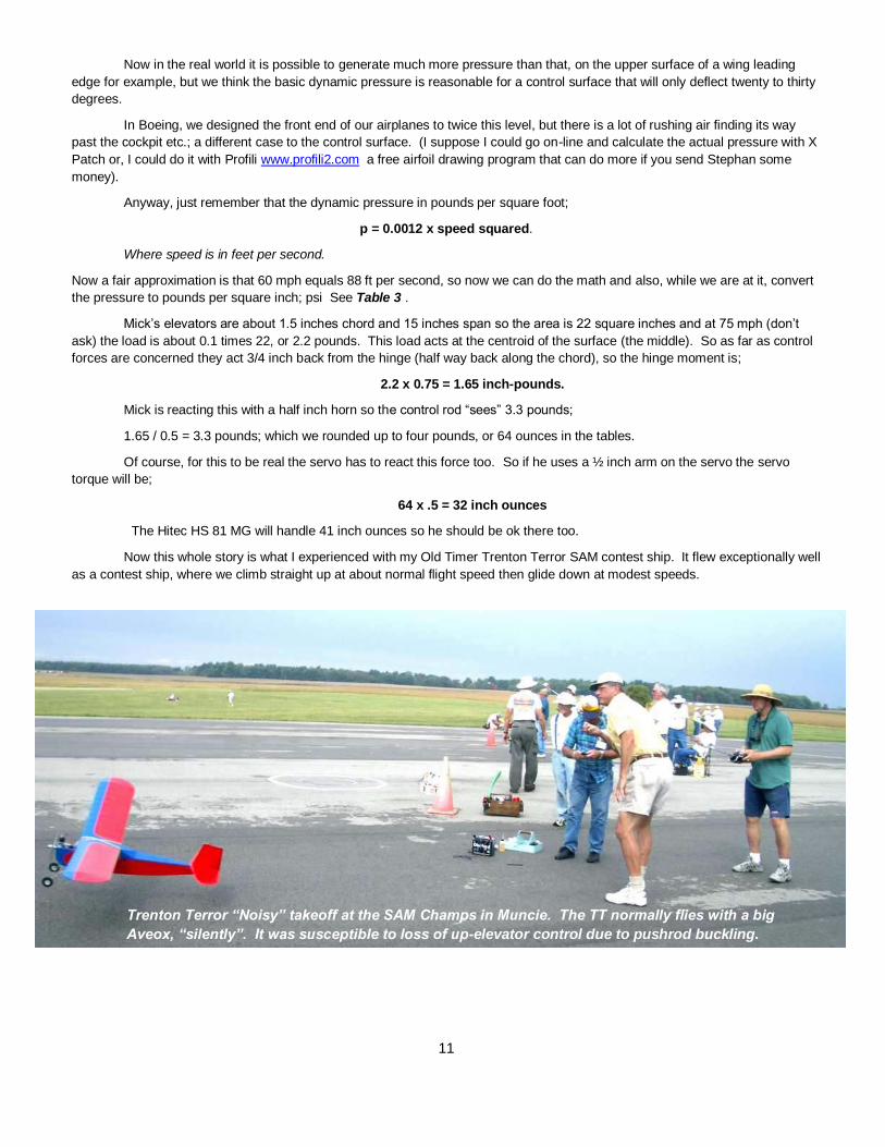
Now this whole story is what I experienced with my Old Timer Trenton Terror SAM contest ship. It flew exceptionally well
as a contest ship, where we climb straight up at about normal flight speed then glide down at modest speeds.
Trenton Terror “Noisy” takeoff at the SAM Champs in Muncie. The TT normally flies with a big
Aveox, “silently”. It was susceptible to loss of up-elevator control due to pushrod buckling.

12
After the contest I flew it at our local field and thought “hey, this is a pretty good sport plane too: So I began to throw it
around like an aerobat; well, maybe just a sport plane. And what do you know, I put it in the top of my least favorite tall tree, and,
following its recovery (it was not badly damaged) I did indeed discover that the graphite tube pushrod buckled under modest
loads.
My fix was a half distance restraint that was easy to install on this stick balsa structure; just strip the covering over one
bay and add the pair of transverse sheet balsa supports – a bit like the Pilgrim stocks clamped around the pair of pushrods, like
legs. Add the covering and I was back in business, but I wish I had done it that way to begin with.
There are, of course, other ways to tackle the control problem including pull-pull and snake-in-tube types, each has its advantages
and disadvantages, so, as with much of our hobby, the fun is in thinking out the options and selecting the one you like best. But
while you are doing so, think about the push rod buckling problem and tip your hat to Leonhard Euler.
Dave Harding
Postscript;
The inclusion of this article was prompted by Joe
Mesko's recent experiences with his foamy F-22.
In the first outing the model seemed to fly ok but
when the nose dropped it couldn't be recovered.
Joe found the battery had come lose and thought
this was the problem.
The second outing, first flight also had the battery
come lose. This time sliding into the prop; which
severed the balance wires!
But this was fixed and the second flight begun,
again with good looking results. But once again
when the nose dropped it just flew into the ground,
bending the nose again.
But what cause the problem. Well, a test of control
power by holding the elevons while applying full up
showed the pushrods buckling. The connections
were made so up required the pushrods to carry
compression loads! Euler's Revenge indeed.
Mid-point pushrod steady in the balsa
stick structure of the Trenton Terror
Joe Mesko with his F-22 foamy
featuring wire pushrods that
buckle under high loads

13
Even More on High Speed Rotorcraft.
Clearly the US Government, in the form of the Defense Advanced Research Projects Agency, DARPA, must have been reading our columns because they have decided to have another go at breaking free from the gloom of the ANSER Wheel syndrome; hardly any of the VTOL airplane "good ideas" ever get built, much less turned into a service airplane. So read the recent article on their new initiative.
The US military’s advanced concepts wing wants an ambitious, high-speed vertical take-off and landing aircraft. But can it succeed where others have failed? Imagine an aircraft that combines a helicopter’s ability to take off and land from almost anywhere, with the speed and range of a fixed wing aircraft. That’s precisely what aviation enthusiasts have dreamed of building for well over 50 years. In fact, so many efforts have been made to get a vertical takeoff and landing (VTOL) aircraft off the ground that even advocates of the concept often refer to the “wheel of misfortune,” a diagram that depicts the dozens of mostly failed concepts. (The ANSA Wheel)
Many never got off the blackboard, and only three have ever been flown operationally by the military – the main customer for these vehicles.
But now, the Pentagon’s Defense Advanced Research Projects Agency (Darpa) is taking another spin at the “wheel”. This week, the agency announced a new X-plane program, which will seek to build a prototype aircraft to demonstrate a better VTOL design. That means more than just brushing off old ideas: the agency is hoping for an entirely fresh approach.
"Strapping rockets onto the back of a helicopter is not the type of approach we're looking for,” Ashish Bagai, Darpa program manager said in a statement announcing the new program. “The engineering community is familiar with the numerous attempts in the past that have not worked. This time, rather than tweaking past designs, we are looking for true cross-pollinations of designs and technologies from the fixed-wing and rotary-wing worlds.”
Indeed, the Pentagon agency is seeking what it calls the “elegant confluence” of different engineering designs and approaches to a VTOL aircraft.
There are, as the wheel shows, numerous to choose from. VTOL concepts over the years have included various ingenious solutions for powering and lifting these craft including tilt-rotor aircraft, tilt-wing, vectored thrust, tilt prop and tilt jets, just to name a few. A few have even been used operationally, such as the US military’s tilt-rotor V-22 Osprey; the iconic Harrier, which relies on vectored thrust to control its movements; and the Soviet Yak-38, another vectored thrust machine. But many more never got anywhere near the battlefield, such as a class of aircraft that stood on their tails – like rockets – for lift-off (These impractical designs included the Lockheed XFV-1 and the Convair XFY-1 Pogo.)
14
‘Art of the possible’
The traditional problem with VTOL aircraft has been the tremendous complexity involved in having to transition from horizontal flight to vertical flight. Many of the schemes, which combine rotors and wings, or involve tilting some component of the aircraft, make for technically elaborate designs that are often impractical to operate and fly.
That Darpa would try to tackle the VTOL problem, even after so many failures, is not surprising. It has long been the tradition of the agency to tackle significant engineering challenges, such as robotics and hypersonics, multiple times until something works. Moreover, the appeal of a VTOL aircraft is simple: helicopters offer the unique ability to take-off and land without an airstrip, providing the military with access to places where fixed-wing aircraft can’t land, while fixed-wing aircraft offer greater speed and range.
The question, now, however, is whether DARPA can come up with anything new. And on that point, not everyone is optimistic.
“The number one problem in the aeronautical sense, with VTOL, is you’re trying to have it all, and in aviation, everything is a tradeoff,” says Roger Connor, curator at the Smithsonian’s Air and Space Museum in Washington DC. “This is really, really hard to do, this is harder than rocket science in a lot of ways,” says Connor. “You’re trying to do something that is counterintuitive, and it’s not obvious that you’re going to have success.”
Nor is it even clear that an entirely fresh approach to the problem is what is needed. Richard Hallion, a former senior advisor to the US Air Force and aerospace historian says there have been improvements in established technology over the years - composite materials, fly-by-wire flight controls, and better propulsion - which may make past VTOL concepts now feasible. “Many of those are waiting to be rediscovered or mined,” he says. “Frankly the history of aerospace technology is one of constant reinvention, reinterpretation, and to a certain degree, rediscovery. That’s not a bad thing.”
No one denies that the road to VTOL aircraft is littered with the corpses of past aircraft, including several Darpa programs, but proponents argue that that’s the whole point of the new initiative. Mark Moore, a Nasa engineer who has specialized in VTOL aircraft for three decades, says he’s excited about Darpa’s plans, but cautions that the example included in a graphic announcing the programme, showing a fan-in-wing design, is not likely the solution. “I would be very surprised if the resulting concepts ended up being fan-in-wing concepts as shown in this graphic,” he says. “Fan-in-Wing were pretty much the least successful of all the VTOL approaches attempted by Nasa and the [Department of Defence] over the past 60 years; they have fundamental transition problems [between take-off and forward flight] that the new technologies available do not solve.” Instead, Moore suggests that advances in electric propulsion and automation will ultimately lead to entirely new concepts.
Mike Hirschberg, executive director of the American Helicopter Society International, is also optimistic. A new X-plane program, like the one Darpa has started, offers a real opportunity – and money - to tackle an age-old problem, says Hirschberg, who previously served as a consultant to Darpa for over a decade.
Hirschberg, who tracks VTOL aircraft design, and updated the famous “wheel,” disagrees that it is in fact a “wheel of misfortune” (that nickname came about years after the original wheel was developed). It’s true that of the dozens of VTOL concepts, only three have been fielded, but that doesn’t mean the idea is futile, he says.
One could use the same wheel to depict ideas for conventional takeoff and landing aircraft, and perhaps come to a similarly bleak picture. “I don’t know if it is as bleak, but it’s probably not that much better,” he says.
Darpa’s project, while high-risk, is not without a solid base: internal studies done by the agency demonstrate that a VTOL aircraft is feasible. That challenge is simply identifying a design that will make it work practically.
“If you start with a clean sheet and ask: what is the art of the possible, and throw open the door to unconventional approaches, you get a lot more creative ideas, and a lot more innovative ideas,” says Hirschberg. “A lot of them, after full analysis may not work, or may not have a compelling capability that outweighs the cost, or penalties, but maybe there will be a breakthrough, maybe you’ll be able to do something. “
There is, he acknowledged, a great deal of disbelief from people about the Darpa project, and some aviation experts may wonder if the agency is crazy. “Maybe it is, but maybe someone is crazy enough out there to come up with a new idea or a new approach to an old concept.”
http://www.bbc.com/future/story/20130228-x-plane-plans-for-radical-takeoff

15
Propstoppers at the Euro SAM RC Champs
Our club secretary Dick Bartkowski and his wife Cathy travelled to Hungary to fly in the Euro SAM RC Champs XI. The trip began with some drama as they planned to fly to Nuremburg via Paris to connect with a Viking Danube Cruise that would take them to Budapest. Drama because up to the day before departure the French air traffic controllers were on strike and the Danube River was at the highest flood level ever measured. Nevertheless, they seem to have made it and did indeed arrive at the field on time. The flying site was about one hundred miles south of Budapest on an airfield in the small town of Jakabszallas. Like other former Soviet nations the Jakabszallas field supports sport flying of all kinds and a decent level of supporting facilities including a few hangers and office space but best of all a decent café / bar.

16
This one also has an excellent hotel as part of the facility. Dick reports the field is large, flat and well groomed, in fact ideal for the SAM competition. Here is Dick's wife Cathy standing on the hard shoulder adjacent to hangers and the field on the day before the meeting began. I believe all these Eastern European flying fields were Mig dispersal bases.
Many of the Eastern Europeans like to camp on the field and facilities are always available for them. If I may interject a story here from the Czech event I attended in 2005. After a long day's flying we, the US contingent were leaving the field to go to our hotel and change for the evening's banquet to be held in the hanger. On our way off the field we encountered a group of Czech flyers all sitting round a card table on which there was a very large bottle of what looked like wine. There was also a somewhat smaller bottle filled with a clear liquid. Neither bottle had labels. We exchanged a few words as we passed and I joked about the bottles. On our return an hour or so later they were still there, and the wine bottle was empty. But they hailed us and beckoned us over whereupon they slapped down a shot glass and filled it with the clear liquid. What to do? Well, not start an international incident. So, "salud" and throw it down. WONDERFUL FIRE WATER; the most marvelous plum brandy, or slivovitz; extraordinary! Unfortunately my American companion tried to follow and almost choked. But we passed the test.

17
This is the eleventh Euro SAM RC Champs, an event instituted by a group of Europeans who had frequented the US SAM Champs and wondered why they didn't have one in Europe.

18
The 2013 entries received before the event
34 Hungarian 69 OTVR Glider 25 Italian 64 ELOT Electric Old Timer
24 Czech 12 OTMR A Old Timer power A
18 Slovak 19 OTMR B Old Timer power B 3 USA 10 NMR Nostalgia
3 Belgian 12 NMR 2,5 Nostalgia 2.5 cc
3 Austrian 36 Texaco 1 San Marino 42 1/2A Texaco Cox 049
1 German 44 Speed 400
1 Spanish 25 El.Rubber Electric Rubber
A total of 10 countries, 113 competitors, 339 models
Gliders are very popular at these events and this year again there were more entries in this category than any other. They fly in six rounds, each with a time limit, using Hi-Start launches. This picture was from the 2007 event in Slovakia. Dick Bartkowski built a new model for the ELOT event that together with his Mick Harris built Skyrocket UK electric powered rubber model would fit in his hard sided golf bag for transport to the meet. Also in the US contingent was Ed Hamler, the US SAM President and member of the Euro SAM committee. Ed has supported every one of the Euro Champs To-date. The following picture is of Ed on the field in Hungary readying his Lanzo Airborne plane which he leaves in Italy for each event.

19
Here is Dick with his two models in Hungary. He will fly the Lanzo RC Champion, below, in both ELOT and Speed 400 events. The British Skyrocket electric powered rubber model on the left will be flown in an event similar to one we fly in the US. You get at 60 second climb and glide / thermal for seven minutes. If more than one competitor achieves the seven minute maximum in two of three flights there is a flyoff where the duration is unlimited. Longest flight wins.
Dick's model has an unusual freewheeling propeller arrangement. On startup Dick engages a clutch through which power is driven. When the motor stops the prop overruns the clutch to freewheel and minimize drag. This feature was of great interest at the meet and Dick's first flight was a stunner, reaching above the lower cool air into a great thermal from which his descent was difficult and time consuming. Here are some other pictures that have been posted to the web.

20

21

22

23
Here is part of the opening ceremony lineup of nations.
Here is a YouTube video of the meet. Not very good content for the flying but it does give you some idea of the flying site and facilities; http://www.youtube.com/watch?v=d5ycwEmwBh0 Here are some other links; : http://mkalka.rajce.idnes.cz/ME_Madarsko_2013/ and some photos are here : http://www.mkbardejov.sk/ME%202013%20Jakabszallasz%20-%20Ma%C4%8Farsko
and some photos here : http://www.sam78.cz/modules.php?name=coppermine&file=thumbnails&album=51
videos at youtube from Tiziano Bortolai (Italy) :
http://www.youtube.com/watch?v=2oYlTPQfGoU http://www.youtube.com/watch?v=Y35HDnSoE8w
http://www.youtube.com/watch?v=oX3QQF8NJjY photos at youtube (from Tiziano) :
http://www.youtube.com/watch?v=pc48hUvQ8OU
US SAM President Ed Hamler with his Anderson Spitfire
ignition powered Lanzo Airborne on the wet and windy day
Ed was the meet's Grand Champion.
Many thanks to Fero Swiety from Slovakia for the
links to the various sites with pictures and videos.