Embed Size (px)
Citation preview
TSS 01 - USER MANUAL SpaceScan Series
Photoelectric light curtains
Website: www.telcosensors.com Warning V 1.31 Part Number: 0666220723
E-Mail: [email protected]
This product is not a safety system and must not be used as such. It is not designed for personnel safety applications, and must not be used as a stand alone personnel safety system.
October 2012 edition
Made in Denmark Telco A/S reserves the right to make changes without prior notice
tel
!
EN
Product Data
Electrical Data SST (Transmitter) SSR (Receiver) Supply voltage 12 — 30 V dc Max. Voltage ripple 15 % (within supply range) Current consumption 100 mA (RMS) 50 mA Max. output load - 200 mA Reverse polarity protected Yes Short circuit protected - Yes Inductive load protection - Yes
Environmental Data Light immunity @5º incidence > 100.000 lux Temperature, operation -30 to + 60 ºC Sealing class IP 67
Marking
Available Models Model Beam spacing Sensing Range
Transmitter SST 01-10-xxx-xxx-05-H-1D1-0.5-J5 5 mm
10 m SST 01-10-xxx-xxx-10-H-1D1-0.5-J5 10 mm SST 01-10-xxx-xxx-20-H-1D1-0.5-J5 20 mm
Receiver
SSR 01-4-xxx-xxx-05-H-1D1-0.5-J8 5 mm 0 m - 4 m SSR 01-4-xxx-xxx-10-H-1D1-0.5-J8 10 mm
SSR 01-4-xxx-xxx-20-H-1D1-0.5-J8 20 mm SSR 01-10-xxx-xxx-05-H-1D1-0.5-J8 5 mm
1 m — 10 m SSR 01-10-xxx-xxx-10-H-1D1-0.5-J8 10 mm SSR 01-10-xxx-xxx-20-H-1D1-0.5-J8 20 mm
Connection
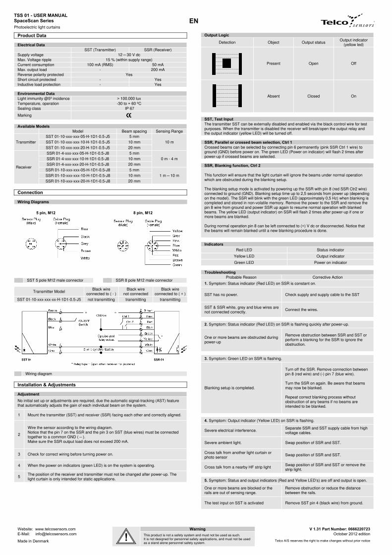
Wiring Diagrams
5 pin, M12 8 pin, M12
SST 5 pole M12 male connector SSR 8 pole M12 male connector
Transmitter Model Black wire
connected to ( - ) Black wire
not connected Black wire
connected to ( + ) SST 01-10-xxx-xxx-xx-H-1D1-0.5-J5 not transmitting transmitting transmitting
Wiring diagram
Installation & Adjustments
Adjustment
No initial set up or adjustments are required, due the automatic signal-tracking (AST) feature that automatically adjusts the gain of each individual beam on the system.
1 Mount the transmitter (SST) and receiver (SSR) facing each other and correctly aligned.
2
Wire the sensor according to the wiring diagram. Notice that the pin 7 on the SSR and the pin 3 on SST (blue wires) must be connected together to a common GND ( — ). Make sure the SSR output load does not exceed 200 mA.
3 Check for correct wiring before turning power on.
4 When the power on indicators (green LED) is on the system is operating.
5 The position of the receiver and transmitter must not be changed after power-up. The light curtain is only intended for static applications.
Output Logic
Detection Object Output status Output indicator
(yellow led)
Present Open Off
Absent
Closed On
SST, Test Input The transmitter SST can be externally disabled and enabled via the black control wire for test purposes. When the transmitter is disabled the receiver will break/open the output relay and the output indicator (yellow LED) will be turned off.
SSR, Parallel or crossed beam selection, Ctrl 1 Crossed beams can be selected by connecting pin 6 permanently (pink SSR Ctrl 1 wire) to ground (GND) before power on. The green LED (Power on indicator) will flash 2 times after power-up if crossed beams are selected.
SSR, Blanking function, Ctrl 2 This function will ensure that the light curtain will ignore the beams under normal operation which are obstructed during the blanking setup. The blanking setup mode is activated by powering up the SSR with pin 8 (red SSR Ctr2 wire) connected to ground (GND). Blanking setup time up to 2,5 seconds from power up (depending on the model). The SSR will blink with the green LED (approximately 0,5 Hz) when blanking is completed and stored in non-volatile memory. Remove the power to the SSR and remove the pin 8 wire from ground and power SSR up again to resume normal operation with blanked beams. The yellow LED (output indicator) on SSR will flash 2 times after power-up if one or more beams are blanked. During normal operation pin 8 can be left connected to (+) V dc or disconnected. Notice that the beams will remain blanked until a new blanking procedure is done.
Indicators
Red LED Status indicator
Yellow LED Output indicator
Green LED Power on indicator
TroubleshootingProbable Reason Corrective Action
1. Symptom: Status indicator (Red LED) on SSR is constant on.
SST has no power. Check supply and supply cable to the SST
SST & SSR white, grey and blue wires are not connected correctly.
Connect the wires.
2. Symptom: Status indicator (Red LED) on SSR is flashing quickly after power-up.
One or more beams are obstructed during power-up
Remove obstruction between SSR and SST or perform a blanking for the SSR to ignore the obstruction.
3. Symptom: Green LED on SSR is flashing.
Blanking setup is completed.
Turn off the SSR. Remove connection between pin 8 (red wire) and (-) pin 7 (blue wire). Turn the SSR on again. Be aware that beams may now be blanked. Repeat correct blanking process without obstruction of any beams if no beams are intended to be blanked.
4. Symptom: Output indicator (Yellow LED) on SSR is flashing.
Severe electrical interference. Separate SSR and SST supply cable from high voltage cables.
Severe ambient light. Swap position of SSR and SST.
Cross talk from another light curtain or photo sensor
Swap position of SSR and SST.
Cross talk from a nearby HF strip light Swap position of SSR and SST or remove the strip light.
5. Symptom: Status and output indicators (Red and Yellow LED’s) are off and output is open.
One or more beams are blocked or the rails are out of sensing range.
Remove obstruction or reduce the distance between the rails.
The test input on SST is activated Remove SST pin 4 (black wire) from ground.

TSS 01 – BEDIENUNGSANLEITUNG Telco SpaceScan Series
Lichtgitter
Website: www.telcosensors.com Warnung ! V 1.31 Part Number: 0666220723
E-Mail: [email protected]
Dieses Produkt ist kein Sicherheitssystem und darf nicht als solches verwendet werden. Es ist nicht für Personensicherheitsanwendungen bestimmt und darf nicht allein als ein Personen-Sicherheitssystem verwendet werden.
Oktober 2012 edition
Made in Denmark Telco A/S reserves the right to make changes without prior notice
tel
!
DE
Technische Daten
Elektrischer Anschluss SST (Sender) SSR (Empfänger) Betriebsspannung 12 — 30 VDC Max. Restwelligkeit 15 % (innerhalb des Spannungsbereiches) Stromaufnahme 100 mA (RMS) 50 mA Max. Ausgangstrom - 200 mA Verpolungsschutz ja Kurzschlussschutz - ja Induktivlastschutz - ja
Umgebungsparameter Fremdlichtunempfindlichkeit @5º Einfallswinkel
> 100.000 lux
Betriebstemperatur -30 ... + 60 ºC Schutzklasse IP 67
Zulassung
Verfügbare Modelle Modell Kanalabstand Reichweite
Sender SST 01-10-xxx-xxx-05-H-1D1-0.5-J5 5 mm
10 m SST 01-10-xxx-xxx-10-H-1D1-0.5-J5 10 mm SST 01-10-xxx-xxx-20-H-1D1-0.5-J5 20 mm
Empfänger
SSR 01-4-xxx-xxx-05-H-1D1-0.5-J8 5 mm 0 m - 4 m SSR 01-4-xxx-xxx-10-H-1D1-0.5-J8 10 mm
SSR 01-4-xxx-xxx-20-H-1D1-0.5-J8 20 mm SSR 01-10-xxx-xxx-05-H-1D1-0.5-J8 5 mm
1 m — 10 m SSR 01-10-xxx-xxx-10-H-1D1-0.5-J8 10 mm SSR 01-10-xxx-xxx-20-H-1D1-0.5-J8 20 mm
Anschluss
Anschlussdiagramm
5 pin, M12 8 pin, M12
SST M12-Stecker; 5-polig SSR M12-Stecker; 8-polig
Sender schwarzer Draht
an GND schwarzer Draht
offen schwarzer Draht
An +Ub SST 01-10-xxx-xxx-xx-H-1D1-0.5-J5 Sender deaktiviert Sender aktiviert Sender akitiviert
Anschlussdiagramm
Installation & Einstellungen
Einstellungen
Aufgrund der AST-Funktion ist kein Set-Up oder weitere Einstellungen notwendig. Jeder Kanal wird automatisch eingestellt und justiert.
1 Montieren Sie Sender (SST) und Empfänger (SSR) so, dass diese sich direkt gegenüber stehen.
2
Verdrahten Sie die Leisten entsprechend der Anschlussbilder. Bitte beachten Sie, dass Pin 7 von der SSR und Pin 3 von SST (blaue Kabel) an eine gemeinsame Masse GND ( — ) angeschlossen werden. Stellen Sie sicher, dass der Laststrom nicht größer als 200mA ist.
3 Auf korrekte Verdrahtung überprüfen und Betriebsspannung einschalten.
4 Wenn die grünen LED’s eingeschaltet sind, ist das System einsatzbereit.
5 Achtung ! Die Leisten dürfen nach Anlegen der Betriebsspannung nicht mehr verschoben werden !
Ausgangs-Logik Detektion Objekt Ausgang gelbe Signal-LED
Vorhanden Offen Aus
Nicht vorhanden
Geschlossen An
SST, Test -Eingang
Für Testzwecke kann der Sender mittels schwarzen Anschlussdraht aktiviert bzw. deaktiviert werden. Wenn der Sender deaktiviert wird, öffnet der Ausgang und die gelbe LED erlischt.
SSR, Strahlauswahl, Anschluss Ctrl 1
Gekreuzte Strahlen können mit dem Anschluss Crtl1(Pink) am Empfänger SSR aktiviert werden, wenn dieser Eingang vor Anlegen der Betriebsspannung auf GND gelegt wurde. Die grüne LED (Betriebsspannung) blinkt nach dem Einschalten 2 mal, wenn die gekreuzten Strahlen aktiviert sind.
SSR, Blanking-Funktion, Anschluss Ctrl 2
Mit dieser Funktion kann man Strahlen ausblenden, die sich dauerhaft im Erfassungsbereich befinden, die aber nicht als Unterbrechung detektiert werden sollen. Die Blanking-Funktion wir aktiviert, indem man vor Anlegen der Betriebsspannung PIN 8(rot) auf GND legt. Die Einlernzeit dauert ca. 2,5 s. (Abhängig vom Modell). Die grüne LED beim Empfänger SSR blinkt im 0,5 Hz-Takt, wenn der Einlernvorgang beendet worden ist und die Parameter in dem internen Speicher geschrieben worden sind. Schalten Sie die Betriebsspannung wieder aus, entfernen Sie die Verbindung von GND zu PIN 8 und schalten Sie die Spannung wieder ein. Die entsprechenden Strahlen sind nun ausgeblendet. Die gelbe LED blinkt 2 mal beim Einschalten der Betriebsspannung wenn ein oder mehrere Strahlen ausgeblendet sind. Pin 8 kann während des Betriebes an +Ub angeschlossen werden, oder offen bleiben. Die Strahlen bleiben solange ausgeblendet, bis die Einlernprozedur wiederholt wird.
Anzeigen
rote LED Status-Anzeige
gelbe LED Schaltausgang
grüne LED Betriebsspannung
FehlerbehebungMögliche Ursache Korrekturmaßnahme
1. Symptom: Status-Anzeige (rote LED) in Empfängerleiste SSR leuchtet konstant.
Sender SST hat keine Betriebsspannung Spannung und Kabel/Anschluss prüfen
SST & SSR weiße, graue und blaue Anschlussdrähte sind nicht korrekt angeschlossen.
Anschlüsse korrekt herstellen
2. Symptom: Status-Anzeige (rote LED) in Empfängerleiste SSR blinkt schnell nach dem Einschalten.
Ein oder mehrere Strahlen sind beim Einschalten unterbrochen.
Beseitigen Sie die Unterbrechung oder aktivieren Sie die Blanking-Funktion
3. Symptom: grüne LED in Empfängerleiste SSR blinkt
Blanking-Einlern-Vorgang ist beendet
Schalten Sie die Betriebsspanunng aus. Trennen Sie die Verbindung zwischen Pin 8 (roter Draht) und (-) Pin 7 (blauer Draht). Betriebsspannung einschalten. Die entsprechenden Strahlen sind nun ausgeblendet. Den Vorgang wiederholen, bis alle gewünschten Strahlen ausgeblendet sind.
4. Symptom: Schaltausgangsanzeige (gelbe LED) in Empfängerleiste SSR blinkt
Einfluss elektrischer Störungen Anschlusskabel von SSR und SST von Hochspannungskabeln entfernen.
Einfluss Fremdlicht Positionen Sender und Empfänger tauschen.
Übersprechen von anderen IR-Systemen Positionen Sender und Empfänger tauschen.
Übersprechen durch HF-EVG Positionen Sender und Empfänger tauschen.
5. Symptom: Status- und Schaltausgangsanzeige (rote und gelbe LED) leuchten nicht und der Ausgang ist offen
Ein oder mehrere Strahlen sind unter-brochen oder die Reichweite ist überschritten.
Unterbrechung entfernen oder die Reichweite verringern.
Testeingang an SST ist aktiviert. Anschluss Pin 4 (schwarzer Draht) von Masse entfernen.

TSS 01 – MANUEL D’UTILISATEUR Série SpaceScan
Barrière Photoélectrique
Website: www.telcosensors.com Attention V 1.31 Part Number: 0666220723
E-Mail: [email protected]
Ce produit n’est pas un système de sécurité et ne peut pas être employé en tant que tel. Il n’est pas conçu pour assurer la sécurité des personnes et il ne peut pas être employé comme système de sécurité Homme-Machine.
Edition octobre 2012
Fabriqué au Danemark Telco A/S reserves the right to make changes without prior notice
tel
!
FR
Caractéristiques techniques
Caractéristique électrique SST (émetteur) SSR (récepteur) Alimentation 12 — 30 V dc Ondulation max. 15 % Consommation 100 mA (RMS) 60 mA Courant de sortie maximum - 200 mA Protection contre l’inversion de polarité Oui Protection contre les courts-circuits - Oui Protection contre charges inductives - Oui
Caractéristiques d’ environnement Immunité à la lumière @ 5° d’incidence > 100.000 lux Température de fonctionnement -30 à + 60 ºC Indice de protection IP 67
Approbation
Modèles Modèle Résolution Portée
Emetteur SST 01-10-xxx-xxx-05-H-1D1-0.5-J5 5 mm
10 m SST 01-10-xxx-xxx-10-H-1D1-0.5-J5 10 mm SST 01-10-xxx-xxx-20-H-1D1-0.5-J5 20 mm
Récepteur
SSR 01-4-xxx-xxx-05-H-1D1-0.5-J8 5 mm 0 m - 4 m SSR 01-4-xxx-xxx-10-H-1D1-0.5-J8 10 mm
SSR 01-4-xxx-xxx-20-H-1D1-0.5-J8 20 mm SSR 01-10-xxx-xxx-05-H-1D1-0.5-J8 5 mm
1 m — 10 m SSR 01-10-xxx-xxx-10-H-1D1-0.5-J8 10 mm SSR 01-10-xxx-xxx-20-H-1D1-0.5-J8 20 mm
Connexions
Schémas de raccordements
5 pin, M12 8 pin, M12
SST-connecteur 5 fiche M12 (male) SSR-connecteur 8 fiche M12 (male)
Modèle émetteur Fil noir
connecté au ( - ) Fil noir
pas connecté Fil noir
connecté au ( + ) SST 01-10-xxx-xxx-xx-H-1D1-0.5-J5 ne transmet pas transmet transmet
Connexions
Installation & Réglages
Réglages Le SG1 ne nécessite aucun réglage car une fonction d’ajustement automatique (AST) élimine tout réglage. Le niveau de signal de chaque canal est ajusté automatiquement aux conditions de fonctionnement.
1 Montez les détecteurs(SST et SSR) dans une position correcte et alignés précisément.
2
Connectez le détecteur selon le schéma de raccordements. Notez que la fiche 7 sur la SSR et la fiche 3 sur la SST (fils bleus) doivent être connectés ensemble à une commune GND (-). Assurez vous que la charge ne dépasse pas 200 mA.
3 Vérifier que toutes les connexions sont correctes avant de mettre en marche.
4 Quand l’indicateur sous tension est allumé (LED verte) le système est opérationnel.
5 La position du récepteur et émetteur ne doit pas être changée après mise sous tension. Le rideau est seulement destiné pour des applications statiques.
Logique de sortie
Détection Objet Statut de la sortie Indicateur de sortie allumé (LED jaune)
Présent Ouverte Non
Absent
Fermée Oui
SST, Test Input L’émetteur SST peut être activé ou désactivé de l’extérieur, par un fil de contrôle, afin d’effectuer des test. . Quand l’émetteur est désactivé la sortie du récepteur change et l'indicateur de sortie (LED jaune) est désactivée.
SSR, Sélection de faisceau parallèles ou croisés, Ctrl 1 Faisceaux croisées peuvent être sélectionnés en reliant la fiche 6 (fiche SSR fil Ctrl1) au masse avant de mettre sous tension. La LED verte (indicateur sous tension) clignote 2 fois après mise sous tension si les faisceaux croisées sont sélectionnées.
SSR, fonction de désactivations des faisceaux, Ctrl 2
Cette fonction s'assurera que le rideau va ignorer les faisceaux sous un fonctionnement normal qui sont obstruées pendant l'installation de désactivations des faisceaux.
Le mode d'installation découpage est activé par la mise sous tension de SSR avec fiche 8 (fil rouge de SSR Ctr2) relié à la terre (-). Le temps d'installation de découpage est jusqu'à 2,5 secondes de mise sous tension (selon le modèle). La LED verte (environ 0,5 Hz) du SSR clignotera quand le désactivation est terminé et stockée dans la mémoire. Supprimer le mis sous tension du SSR et supprimer le fil de la fiche 8 du terre (-) et remis le SSR sous tension pour reprendre un fonctionnement normal avec des faisceaux désactivées. La LED jaune (indicateur de sortie) sur SSR clignote 2 fois après un mis sous tension si un ou plusieurs faisceaux est masqué.
Pendant le fonctionnement normal fiche 8 peut être laissé branché à (+) V dc ou déconnecté. Notez que les faisceaux resteront masqué jusqu'à ce qu'une nouvelle procédure de découpage est effectuée.
Indicateurs
LED rouge Indicateur de statut
LED jaune Indicateur d’état de la sortie
LED vert Indicateur sous tension
Résolutions des problèmesRaison probable Action corrective
1. Symptôme: L’indicateur de statut (LED rouge) sur le SSR est allumé en permanence
SST n’est pas alimenter. Vérifier l’alimentation et les fils de la SST
Les fils blancs, gris et bleus de SST & SSR ne sont pas correctement connectés.
Vérifier les connections sur le SST et SSR.
2. Symptôme: L’indicateur de statut (LED rouge) clignote très vite après mis sous tension
Un ou plusieurs faisceaux sont coupés
Supprimer une obstruction entre la SSR et SST ou effectuer la fonction de désactivation des faisceaux pour ignorer l'obstruction.
3. Symptôme: LED vert sur le SSR clignote.
La fonction de désactivation des faisceaux est terminé.
Désactiver la SSR. Supprimer le lien entre la fiche 8 (fil rouge) et (-) fiche 7 (fil bleu). Activer le SSR. Sachez que les faisceaux peuvent maintenant être masqués. Répéter les processus de découpage sans obstructions des faisceaux si aucun faisceaux ne sont destinées à être masqué.
4. Symptôme: Indicateur d’état de la sortie (LED jaune) sur la SSR clignote.
Interférences électriques sévères Séparer les fils d’alimentation du SGR et du SGT des conducteurs haute tension
Milieu très lumineux Changer la position du SSR et du SST.
Une autre barrière ou cellule crée des interférences
Changer la position du SSR et du SST.
Interférence d'une lumière proche de la bande HF
Changer la position du SSR et du SST ou supprimer la lumière
5. Symptôme: Indicateurs de statut et sortie (LED rouge et jaune) sont pas allumées et la sortie n’est pas actif
Un ou plusieurs faisceaux sont coupés ou les barrières sont mis hors portée.
Enlever l'obstruction ou réduire la distance entre les barrières.
L’entrée teste sur SST est activée. Enlever fiche 4 (fil noir) du SST du terre (-).

TSS 01 – MANUAL DE USUARIO Serie SpaceScan
Cortinas Fotoeléctricas
Website: www.telcosensors.com Advertencia V 1.31 Part Number: 0666220723
E-Mail: [email protected]
Este producto no es un sistema de seguridad y no debe ser usado como tal. No está diseñado para aplicaciones de seguridad para personas. No debe ser utilizado como único sistema de seguridad para personas.
Edición: Octubre 2012
Fabricado en Dinamarca Telco A/S se reserva el derecho a realizar cambios sin previo aviso.
tel
!
ES
Especificaciones Técnicas
Datos Eléctricos SST (Emisor) SSR (Receptor) Tensión de alimentación 12 — 30 V cc Tolerancia 15 % Consumo máximo 100 mA (RMS) 60 mA Carga máxima - 200 mA Protec. Inversión de polos Si Protec. Contra cortocircuitos - Si Protec. Carga inductiva - Si
Condiciones de Entorno Inmunidad lumínica @ 5º > 100.000 lux Temperatura de trabajo -30 a + 60 ºC Protección IP 67
Certificados
Modelos Disponibles Modelo Distancia entre canales Rango
Emisor SST 01-10-xxx-xxx-05-H-1D1-0.5-J5 5 mm
10 m SST 01-10-xxx-xxx-10-H-1D1-0.5-J5 10 mm SST 01-10-xxx-xxx-20-H-1D1-0.5-J5 20 mm
Receptor
SSR 01-4-xxx-xxx-05-H-1D1-0.5-J8 5 mm 0 m - 4 m SSR 01-4-xxx-xxx-10-H-1D1-0.5-J8 10 mm
SSR 01-4-xxx-xxx-20-H-1D1-0.5-J8 20 mm SSR 01-10-xxx-xxx-05-H-1D1-0.5-J8 5 mm
1 m — 10 m SSR 01-10-xxx-xxx-10-H-1D1-0.5-J8 10 mm SSR 01-10-xxx-xxx-20-H-1D1-0.5-J8 20 mm
Conexiones
Diagrama de Conexiones
5 pines, M12 8 pines, M12
SST 5 polos M12 conector macho SSR 8 polos M12 conector macho
Modelo Emisor Cable negro
conectado a ( - ) Cable negro no
conectado Cable negro
conectado a ( + ) SST 01-10-xxx-xxx-xx-H-1D1-0.5-J5 SST desactivado SST activado SST activado
Diagrama de conexiones
Instalación y Ajustes
Ajustes No se requiere de ningún ajuste inicial o puesta en marcha; el sistema AST (Automatic Signal Tracking feature), ajusta automáticamente el nivel de ganancia de todos y cada uno de los haces.
1 Instale el emisor (SST) y receptor (SSR) enfrentados uno a otro y correctamente alineados.
2
Conecte el cableado según el diagrama de conexiones. Verifique que el cable azul del pin nº 7 en el receptor (SSR) y pin nº 3 en el emisor (SST) estén conectados a un negativo común - GND ( — ). Asegúrese que la carga no sobrepase los 200 mA.
3 Verifique el cableado y conexiones antes de conectar la alimentación.
4 Cuando los indicadores de alimentación (LED’s verdes) están encendidos, el sistema está funcionando.
5 La emisor y receptor no deben ser cambiados de posición una vez alimentado el sistema. Las cortinas fotoeléctricas deben ser utilizas en posición estática.
SST, Entrada de Test
El emisor SST puede ser desactivado y activado mediante el cable de control (cable negro). Cuando el emisor esté desactivado el receptor desconectará/abrirá la salida relé y el indicador de salida (LED amarillo) se apagará.
Salida Lógica
Detección Objeto Salida Indicador de Salida
(LED amarillo)
Presente Open Apagado
Ausente
Cerrado Encendido
SSR, Selección de haces paralelos o cruzados, Ctrl 1 El modo de haces cruzados se activa conectando el cable rosa (pin 6 en SSR) a GND (negativo) antes de alimentar el sistema. El indicador de alimentación (LED verde) parpadeará dos veces indicando que el modo de haces cruzados está activado.
SSR, Función de Bloqueo, Ctrl 2
Esta función asegura que durante el funcionamiento de la cortina fotoeléctrica se ignoren los canales que hayan sido bloqueados durante el proceso de ajuste. Para entrar en el modo de desactivación de canales (Blanking mode), conectar el cable rojo en el receptor (pin 8 SSR) a negativo GND ( - ). Bloquee físicamente todos aquellos canales que necesiten ser ignorados. A continuación, restablezca la alimentación de la cortina fotoeléctrica. El ajuste automático se realiza en un tiempo no superior a 2,5 segundos, dependiendo del modelo. Cuando el indicador de alimentación, en el receptor SSR (LED verde), comience a parpadear (aprox. 0,5 Hz) el proceso de desactivación de canales (Blanking) se habrá completado y los parámetros se almacenarán en la memoria permanente del sistema. Interrumpa la alimentación y desconecte el pin nº8 del receptor (cable rojo SSR Ctrl2) del negativo GND ( - ). Restablezca la alimentación para volver al modo de funcionamiento normal. Todos aquellos canales que fueron bloqueados durante el proceso de ajuste serán ignorados. Durante el funcionamiento normal, el pin nº8 (cable rojo) puede estar conectado a positivo o no conectado. Los canales permanecerán ignorados hasta que se vuelva a entrar en modo de ajuste (Blanking mode).
IndicadoresLED Rojo Indicador de Estado
LED Amarillo Indicador de Salida
LED Verde Indicador de Alimentación
Guía de Solución de ProblemasPosible causa Solución
1. Síntoma: Indicador de Estado (LED rojo) en el receptor (SSR) constantemente encendido
El emisor no está alimentado. Verifique la alimentación y cableado del emisor.
Cables blanco, gris y rojo en emisor y receptor no conectados correctamente.
Conecte los cables.
2. Síntoma: Indicador de Estado (LED rojo) en SSR receptor parpadea rápidamente después de alimentar la cortina.
Uno o más canales están obstruidos/bloqueados
Elimine la obstrucción entre emisor y receptor o entre en modo de ajuste (blanking mode) para de este modo ignorar los canales bloqueados.
3. Síntoma: Indicador de alimentación (LED verde) en receptor parpadeando.
El ajuste de la función de bloqueo (Blanking setup) se ha completado.
Desconecte alimentación de las cortinas. Desconectar pin nº8 (cable rojo) de pin nº7 (cable azul) negativo. Restablezca la alimentación a la cortina. Tenga en cuenta que algunos canales pueden estar siendo ignorados. Si todos los canales deben permanecer activos, repita el proceso de ajuste (blanking mode) asegurándose que todos ellos están libres de cualquier tipo de obstrucción.
4. Síntoma: Indicador de salida (LED amarillo) en receptor parpadeando.
Alto nivel de interferencia eléctrica. Aleje los cables de alta tensión de los cables de alimentación de los detectores.
Alto nivel de luz ambiental. Intercambie la posición del emisor y receptor.
Interferencia óptica con otra cortina o sensor fotoeléctrico.
Intercambie la posición del emisor y receptor.
Interferencia óptica con fuente de luz fluorescente o alta frecuencia.
Intercambie la posición del emisor y receptor, o elimine la fuente de luz.
5. Síntoma: Indicador de Estado y Salida (LED verde y amarillo) apagados y la salida está abierta. Uno o más canales están bloqueados o emisor y receptor están fuera del rango de alcance.
Elimine la obstrucción o reduzca la distancia entre emisor y receptor.
Entrada de test activada en el emisor. Desconecte cable negro (pin nº 4) en emisor de negativo GND ( - ).

TSS 01 - USER MANUAL SpaceGuard Series
Photoelectric light curtains
Website: www.telcosensors.com Warning V 1.31 Part Number: 0666220723
E-Mail: [email protected]
This product is not a safety system and must not be used as such. It is not designed for personnel safety applications, and must not be used as a stand alone personnel safety system.
October 2012 edition
Made in Denmark Telco A/S reserves the right to make changes without prior notice
tel
!
EN
Dimensions and Descriptions
(* 5 mm channel spacing showed in diagram.)