Embed Size (px)
Citation preview

ETSI TS 129 368 V12.2.0 (2014-10)
Universal Mobile Telecommunications System (UMTS); LTE;
Tsp interface protocol between the MTC Interworking Function (MTC-IWF) and
Service Capability Server (SCS) (3GPP TS 29.368 version 12.2.0 Release 12)
TECHNICAL SPECIFICATION
ETSI
ETSI TS 129 368 V12.2.0 (2014-10)13GPP TS 29.368 version 12.2.0 Release 12
Reference DTS/TSGC-0329368vc20
Keywords LTE,UMTS
ETSI
650 Route des Lucioles F-06921 Sophia Antipolis Cedex - FRANCE
Tel.: +33 4 92 94 42 00 Fax: +33 4 93 65 47 16
Siret N° 348 623 562 00017 - NAF 742 C
Association à but non lucratif enregistrée à la Sous-Préfecture de Grasse (06) N° 7803/88
Important notice
The present document can be downloaded from: http://www.etsi.org
The present document may be made available in electronic versions and/or in print. The content of any electronic and/or print versions of the present document shall not be modified without the prior written authorization of ETSI. In case of any
existing or perceived difference in contents between such versions and/or in print, the only prevailing document is the print of the Portable Document Format (PDF) version kept on a specific network drive within ETSI Secretariat.
Users of the present document should be aware that the document may be subject to revision or change of status. Information on the current status of this and other ETSI documents is available at
http://portal.etsi.org/tb/status/status.asp
If you find errors in the present document, please send your comment to one of the following services: http://portal.etsi.org/chaircor/ETSI_support.asp
Copyright Notification
No part may be reproduced or utilized in any form or by any means, electronic or mechanical, including photocopying and microfilm except as authorized by written permission of ETSI.
The content of the PDF version shall not be modified without the written authorization of ETSI. The copyright and the foregoing restriction extend to reproduction in all media.
© European Telecommunications Standards Institute 2014.
All rights reserved.
DECTTM, PLUGTESTSTM, UMTSTM and the ETSI logo are Trade Marks of ETSI registered for the benefit of its Members. 3GPPTM and LTE™ are Trade Marks of ETSI registered for the benefit of its Members and
of the 3GPP Organizational Partners. GSM® and the GSM logo are Trade Marks registered and owned by the GSM Association.

ETSI
ETSI TS 129 368 V12.2.0 (2014-10)23GPP TS 29.368 version 12.2.0 Release 12
Intellectual Property Rights IPRs essential or potentially essential to the present document may have been declared to ETSI. The information pertaining to these essential IPRs, if any, is publicly available for ETSI members and non-members, and can be found in ETSI SR 000 314: "Intellectual Property Rights (IPRs); Essential, or potentially Essential, IPRs notified to ETSI in respect of ETSI standards", which is available from the ETSI Secretariat. Latest updates are available on the ETSI Web server (http://ipr.etsi.org).
Pursuant to the ETSI IPR Policy, no investigation, including IPR searches, has been carried out by ETSI. No guarantee can be given as to the existence of other IPRs not referenced in ETSI SR 000 314 (or the updates on the ETSI Web server) which are, or may be, or may become, essential to the present document.
Foreword This Technical Specification (TS) has been produced by ETSI 3rd Generation Partnership Project (3GPP).
The present document may refer to technical specifications or reports using their 3GPP identities, UMTS identities or GSM identities. These should be interpreted as being references to the corresponding ETSI deliverables.
The cross reference between GSM, UMTS, 3GPP and ETSI identities can be found under http://webapp.etsi.org/key/queryform.asp.
Modal verbs terminology In the present document "shall", "shall not", "should", "should not", "may", "may not", "need", "need not", "will", "will not", "can" and "cannot" are to be interpreted as described in clause 3.2 of the ETSI Drafting Rules (Verbal forms for the expression of provisions).
"must" and "must not" are NOT allowed in ETSI deliverables except when used in direct citation.
ETSI
ETSI TS 129 368 V12.2.0 (2014-10)33GPP TS 29.368 version 12.2.0 Release 12
Contents
Intellectual Property Rights ................................................................................................................................ 2
Foreword ............................................................................................................................................................. 2
Modal verbs terminology .................................................................................................................................... 2
Foreword ............................................................................................................................................................. 5
1 Scope ........................................................................................................................................................ 5
2 References ................................................................................................................................................ 5
3 Definitions, symbols and abbreviations ................................................................................................... 6
3.1 Definitions .......................................................................................................................................................... 6
3.2 Symbols .............................................................................................................................................................. 6
3.3 Abbreviations ..................................................................................................................................................... 6
4 Tsp reference point ................................................................................................................................... 7
4.1 Tsp Reference model .......................................................................................................................................... 7
4.2 Functional elements ............................................................................................................................................ 7
4.2.1 SCS ............................................................................................................................................................... 7
4.2.2 MTC-IWF ..................................................................................................................................................... 7
5 Procedures over Tsp reference point ........................................................................................................ 8
5.1 General ............................................................................................................................................................... 8
5.2 Reference number handling ................................................................................................................................ 8
5.3 MTC-IWF selection ........................................................................................................................................... 8
5.4 MTC-IWF load control ...................................................................................................................................... 9
5.5 Request and confirmation of a device trigger: .................................................................................................... 9
5.6 Notification of Device trigger .......................................................................................................................... 10
5.7 Request and confirmation of a device trigger recall request: ........................................................................... 10
5.8 Request and confirmation of a device trigger replace request: ......................................................................... 10
6 Tsp protocol ............................................................................................................................................ 11
6.1 Protocol support ............................................................................................................................................... 11
6.1.1 Use of Diameter base protocol .................................................................................................................... 11
6.1.2 Transport protocol ...................................................................................................................................... 12
6.1.3 Advertising Application Support ................................................................................................................ 12
6.2 Initialization and maintenance of connection and session ................................................................................ 12
6.3 Security on the Tsp interface ............................................................................................................................ 12
6.3.1 General ........................................................................................................................................................ 12
6.3.2 Mutual authentication ................................................................................................................................. 12
6.3.3 Security profiles .......................................................................................................................................... 13
6.4 Tsp specific AVPs ............................................................................................................................................ 13
6.4.1 General ........................................................................................................................................................ 13
6.4.2 Device-Action AVP .................................................................................................................................... 14
6.4.3 Device-Notification AVP ........................................................................................................................... 14
6.4.4 Trigger-Data AVP ...................................................................................................................................... 14
6.4.5 Payload AVP .............................................................................................................................................. 15
6.4.6 Action-Type AVP ....................................................................................................................................... 15
6.4.7 Priority-Indication AVP .............................................................................................................................. 15
6.4.8 Reference-Number AVP ............................................................................................................................. 16
6.4.9 Request-Status AVP ................................................................................................................................... 16
6.4.10 Delivery-Outcome AVP ............................................................................................................................. 17
6.4.11 Application-Port-Identifier AVP ................................................................................................................ 17
6.4.12 Old-Reference-Number AVP...................................................................................................................... 17
6.5 Tsp re-used AVPs ............................................................................................................................................. 17
6.5.1 General ........................................................................................................................................................ 17
6.5.2 Supported-Feature-List AVP ...................................................................................................................... 18
6.5.2.1 Use of the Supported-Features AVP ..................................................................................................... 18

ETSI
ETSI TS 129 368 V12.2.0 (2014-10)43GPP TS 29.368 version 12.2.0 Release 12
6.5.2.2 Supported-Feature-List AVP for the Tsp application ........................................................................... 18
6.6 Tsp Messages ................................................................................................................................................... 19
6.6.1 Command-Code Values .............................................................................................................................. 19
6.6.2 Device-Action-Request (DAR) command .................................................................................................. 19
6.6.3 Device-Action-Answer (DAA) command .................................................................................................. 19
6.6.4 Device-Notification-Request (DNR) command .......................................................................................... 20
6.6.5 Device-Notification-Answer (DNA) command .......................................................................................... 20
Annex A (informative): Tsp Message Flows......................................................................................... 21
A.1 General ................................................................................................................................................... 21
A.2 Tsp Submission, T4 Delivery ................................................................................................................. 21
A.3 Tsp failed Submission ............................................................................................................................ 22
A.4 Tsp Submission, Failed T4 Delivery ...................................................................................................... 23
A.5 Tsp Recall Submission, Recall Success ................................................................................................. 24
A.6 Tsp Recall Submission, Recall Failure ................................................................................................... 25
A.7 Tsp Replace Submission, Replace Success ............................................................................................ 25
A.8 Tsp Replace Submission, Replace Failure ............................................................................................. 26
Annex B (informative): Change history ............................................................................................... 28
History .............................................................................................................................................................. 29
ETSI
ETSI TS 129 368 V12.2.0 (2014-10)53GPP TS 29.368 version 12.2.0 Release 12
Foreword This Technical Specification has been produced by the 3rd Generation Partnership Project (3GPP).
The contents of the present document are subject to continuing work within the TSG and may change following formal TSG approval. Should the TSG modify the contents of the present document, it will be re-released by the TSG with an identifying change of release date and an increase in version number as follows:
Version x.y.z
where:
x the first digit:
1 presented to TSG for information;
2 presented to TSG for approval;
3 or greater indicates TSG approved document under change control.
y the second digit is incremented for all changes of substance, i.e. technical enhancements, corrections, updates, etc.
z the third digit is incremented when editorial only changes have been incorporated in the document.
1 Scope The present document provides the stage 3 specification of the Tsp reference point for the present release. The functional requirements and the stage 2 specifications of the Tsp reference point are contained in 3GPP TS 23.682 [2]. The Tsp reference point lies between the Service Capability Server (SCS) and the Machine Type Communication Inter Working Function (MTC-IWF).
2 References The following documents contain provisions which, through reference in this text, constitute provisions of the present document.
- References are either specific (identified by date of publication, edition number, version number, etc.) or non-specific.
- For a specific reference, subsequent revisions do not apply.
- For a non-specific reference, the latest version applies. In the case of a reference to a 3GPP document (including a GSM document), a non-specific reference implicitly refers to the latest version of that document in the same Release as the present document.
[1] 3GPP TR 21.905: "Vocabulary for 3GPP Specifications".
[2] 3GPP TS 23.682: "Architecture enhancements to facilitate communications with packet data networks and applications".
[3] 3GPP TS 29.329: "Sh Interface based on the Diameter protocol".
[4] IETF RFC 791: "Transmission Control Protocol".
[5] IETF RFC 2234: "Augmented BNF for syntax specifications".
[6] IETF RFC 3588: "Diameter Base Protocol".
[7] IETF RFC 4006: "Diameter Credit Control Application".

ETSI
ETSI TS 129 368 V12.2.0 (2014-10)63GPP TS 29.368 version 12.2.0 Release 12
[8] IETF RFC 4960: "Stream Control Transmission Protocol".
[9] IETF RFC 5719: "Updated IANA Considerations for Diameter Command Code Allocations".
[10] 3GPP TS 33.210: "Network Domain Security (NDS); IP network layer security".
[11] 3GPP TS 33.310: "Network Domain Security (NDS); Authentication Framework (AF)".
[12] 3GPP TS 29.336: "Home Subscriber Server (HSS) diameter interfaces for interworking with packet data networks and applications".
[13] 3GPP TS 29.303: "Domain Name System Procedures; Stage 3".
[14] 3GPP TS 23.003: "Numbering, addressing and identification".
[15] 3GPP TS 23.040: "Technical realization of the Short Message Service (SMS)".
[16] 3GPP TS 29.229: "Cx and Dx interfaces based on the Diameter protocol".
[17] 3GPP TS 29.337: "Diameter-based T4 interface for communications with packet data networks and applications ".
3 Definitions, symbols and abbreviations
3.1 Definitions For the purposes of the present document, the terms and definitions given in TR 21.905 [1] and the following apply. A term defined in the present document takes precedence over the definition of the same term, if any, in TR 21.905 [1].
3.2 Symbols For the purposes of the present document, no symbols are defined.
3.3 Abbreviations For the purposes of the present document, the abbreviations given in TR 21.905 [1] and the following apply. An abbreviation defined in the present document takes precedence over the definition of the same abbreviation, if any, in TR 21.905 [1].
AVP Attribute Value Pair CEA Capabilities-Exchange-Answer CER Capabilities-Exchange-Request DAA Device-Action-Answer DAR Device-Action-Request DNA Device-Notification-Answer DNR Device-Notification-Request DNS Domain Name System ESP Encapsulating Security Payload IKE Internet Key Exchange IWF Inter Working Function MTC Machine Type Communication PKI Public key infrastructure SCS Service Capability Server TLS Transport Layer Security
ETSI
ETSI TS 129 368 V12.2.0 (2014-10)73GPP TS 29.368 version 12.2.0 Release 12
4 Tsp reference point
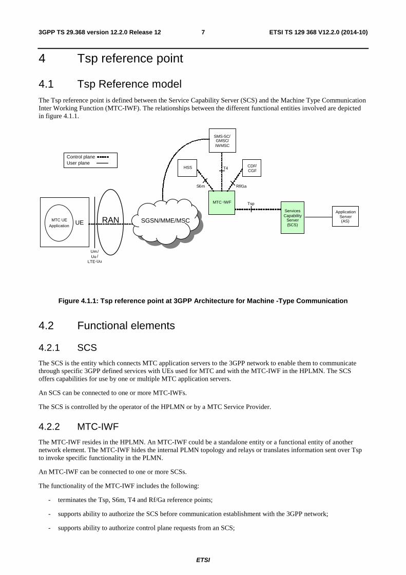
4.1 Tsp Reference model The Tsp reference point is defined between the Service Capability Server (SCS) and the Machine Type Communication Inter Working Function (MTC-IWF). The relationships between the different functional entities involved are depicted in figure 4.1.1.
Services Capability
Server ( SCS )
Tsp MTC - IWF
SMS - SC / GMSC / IWMSC
T 4
S 6 m Rf / Ga
Um / Uu /
LTE - Uu
MTC UE Application UE RAN
HSS
Application Server ( AS )
CDF / CGF
SGSN/MME/MSC
Control plane User plane
Figure 4.1.1: Tsp reference point at 3GPP Architecture for Machine -Type Communication
4.2 Functional elements
4.2.1 SCS
The SCS is the entity which connects MTC application servers to the 3GPP network to enable them to communicate through specific 3GPP defined services with UEs used for MTC and with the MTC-IWF in the HPLMN. The SCS offers capabilities for use by one or multiple MTC application servers.
An SCS can be connected to one or more MTC-IWFs.
The SCS is controlled by the operator of the HPLMN or by a MTC Service Provider.
4.2.2 MTC-IWF
The MTC-IWF resides in the HPLMN. An MTC-IWF could be a standalone entity or a functional entity of another network element. The MTC-IWF hides the internal PLMN topology and relays or translates information sent over Tsp to invoke specific functionality in the PLMN.
An MTC-IWF can be connected to one or more SCSs.
The functionality of the MTC-IWF includes the following:
- terminates the Tsp, S6m, T4 and Rf/Ga reference points;
- supports ability to authorize the SCS before communication establishment with the 3GPP network;
- supports ability to authorize control plane requests from an SCS;

ETSI
ETSI TS 129 368 V12.2.0 (2014-10)83GPP TS 29.368 version 12.2.0 Release 12
- supports the following device trigger functionality:
- reception of a device trigger request from SCS;
- reception of a device trigger recall/replace request from SCS;
- reporting to the SCS the acceptance or non-acceptance of the device trigger request;
- reporting to the SCS the acceptance or non-acceptance of the device trigger recall/replace request;
- reports to the SCS the success, failure or unconfirmed outcome of a device trigger delivery;
- reports to the SCS the success, failure or unconfirmed outcome of the device trigger recall/replace request;
- provides load control information to SCS as part of the response to trigger requests;
- supports ability for secure communication between the 3GPP network and the SCS.
The architecture allows the use of multiple MTC-IWFs within a HPLMN.
5 Procedures over Tsp reference point
5.1 General The following procedures apply over the Tsp reference point:
- Request and confirmation of a device trigger
- Notification of a device trigger
- Recalling or replacing of an already submitted device trigger
5.2 Reference number handling The reference number shall be assigned by the SCS. The reference number shall be provided by the SCS to the MTC-IWF in the first procedure initiated for a specific target of a specific action request (e.g. for a device trigger request towards a specific MTC device). The MTC-IWF and SCS shall use this reference number for all consecutive related procedures (e.g. for a confirmation of device trigger and notification of device trigger).
The reference number shall be kept in MTC-IWF and in SCS until all related procedures for a specific target of a specific action request initiated by the SCS are completed (e.g. until the notification of device trigger is completed).
For each new specific action request other than Device Trigger Recall /Request, the SCS shall assign a reference number, which is different from any other reference number it has previously assigned to any other another action request with not yet completed related procedures.
5.3 MTC-IWF selection To discover the MTC-IWF with which to establish the Tsp session, the SCS may use:
- a pre-configured MTC-IWF identity
- DNS
- Diameter routing
For DNS, the Domain Name System procedures as specified in TS 29.303 [13] may be used by the SCS for MTC-IWF selection. The External Identifier is defined in 3GPP TS 23.003 [14] and is composed of Domain Identifier and Local Identifier. The DNS query can be performed deriving the domain name to be resolved from the Domain Identifier part of the External Identifier.

ETSI
ETSI TS 129 368 V12.2.0 (2014-10)93GPP TS 29.368 version 12.2.0 Release 12
For Diameter Routeing, the Destination Realm should be derived from the Domain Identifier part of the External Identifier.
5.4 MTC-IWF load control Upon receiving a device action request from the SCS:
- if the MTC-IWF determines that the SCS has reached or exceeded the quota of Tsp requests that it is allowed to send, the MTC-IWF may respond to the SCS with a Device-Action-Answer command containing the Request-Status AVP with the value set to QUOTAEXCEEDED.
- if the MTC-IWF determines that the SCS has exceeded its rate of initiating Tsp requests, the MTC-IWF may respond to the SCS with a Device-Action-Answer command containing the Request-Status AVP with a value set to RATEEXCEEDED.
- if the MTC-IWF is in an overload condition, the MTC-IWF may respond to the SCS with a Device-Action-Answer command containing the Result-Code AVP with the value set to DIAMETER_TOO_BUSY, see IETF RFC 3588 [6].
For the above cases, the SCS on receiving the response from MTC-IWF, may provide an indication of the failed request to the application requesting services to the SCS.
Alternatively, for RATEEXCEEDED and DIAMETER_TOO_BUSY, the SCS may implement a backoff timer which when running the SCS does not initiate Tsp requests to the MTC-IWF. Once the timer expires, the SCS may attempt to use the MTC-IWF which was formerly in an overload condition or for which SCS had exceeded the rate of Tsp requests. The algorithm the SCS uses for the backoff timer is out of scope of the 3GPP specification.
5.5 Request and confirmation of a device trigger: In order to request the MTC-IWF to perform a device trigger, the SCS shall send a Device-Action-Request command with the following AVP values within the Device-Action AVP:
a) Action-Type AVP set to the value Device Trigger Request (1)
b) Either MSISDN AVP or External-Id AVP set to the identifier of the MTC device to be triggered
c) SCS-Identifier AVP, containing the identity of the SCS that is requesting a device trigger to the UE
d) Reference-Number AVP, containing a newly assigned reference number the SCS has assigned to the specific action request
e) Trigger-Data AVP containing data to be sent to the MTC device with the trigger by the MTC-IWF in the Payload AVP, priority of the trigger in the Priority-Indication AVP and the triggering application addressed in the device indicated in the Application-Port-Identifier AVP
f) Validity-Time AVP, indicating the validity time of the device trigger request since the time the device action request has been received by the MTC-IWF
After the MTC-IWF has received from the SCS a Device-Action-Request command with device action set to Device Trigger Request (1), after receiving the Device-Trigger-Answer from SMS-SC, the MTC-IWF shall confirm the status of a device trigger request to the SCS by sending a Device-Action-Answer command and shall include the following AVP values within the Device-Notification AVP:
a) Action-Type AVP set to the value Device Trigger Request (1)
b) Reference-Number AVP, containing the reference number received from the SCS for the specific action request
c) Request-Status AVP set to value indicating the status of the device trigger request requested by the SCS
The MTC-IWF may also include the following AVP within the Device-Notification AVP:
a) Either MSISDN AVP or External-Id AVP set to the identifier of the MTC device to be triggered
b) SCS-Identifier AVP, containing the identity of the SCS that requested a device trigger to the UE.

ETSI
ETSI TS 129 368 V12.2.0 (2014-10)103GPP TS 29.368 version 12.2.0 Release 12
If the MTC-IWF concludes that it needs to abort the device trigger, it shall indicate the unsuccessful outcome with the Request-Status AVP and may release the reference number received from the SCS for the specific action request.
5.6 Notification of Device trigger The MTC-IWF shall notify the SCS of the outcome of a device trigger request by sending a Device-Notification-Request command to the SCS with the following AVP values set in the Device-Notification AVP:
a) Action-Type AVP set to the value Delivery Report (2)
b) Either MSISDN AVP or External-Id AVP set to the identifier of the MTC device triggered
c) SCS-Identifier AVP, containing the identity of the SCS that requested a device trigger to the UE
d) Reference-Number AVP as received in the corresponding Device-Action-Request command by the SCS
e) Delivery-Outcome AVP set to the proper value, depending on success, failure or unconfirmed outcome of the delivery of the trigger request by the MTC-IWF to the MTC device
The SCS shall acknowledge the receipt of the Device-Notification-Request command by sending to the MTC-IWF a Device-Notification-Answer command.
When the procedure is completed in the MTC-IWF and the SCS the reference number shall be released.
5.7 Request and confirmation of a device trigger recall request: In order to request the MTC-IWF to perform a device trigger recall, the SCS shall send a Device-Action-Request command with the following AVP values within the Device-Action AVP:
a) Action-Type AVP set to the value Device Trigger Recall (3)
b) Either MSISDN AVP or External-Id AVP set to the identifier of the MTC device to be triggered
c) SCS-Identifier AVP, containing the identity of the SCS that is requesting a device trigger to the UE
d) Reference-Number AVP, containing the assigned reference number the SCS has assigned to the trigger message to be recalled.
After the MTC-IWF has received from the SCS a Device-Action-Request command with device action set to Device Trigger Recall (3), after receiving the Device-Trigger-Answer from SMS-SC the MTC-IWF shall confirm the status of a device trigger recall request to the SCS by sending a Device-Action-Answer command and shall include the following AVP values within the Device-Notification AVP:
a) Action-Type AVP set to the value Device Trigger Recall (3)
b) Reference-Number AVP, containing the reference number of the recalled trigger message from the SCS
c) Request-Status AVP set to value indicating the status of the device trigger recall
If the MTC-IWF concludes that it needs to abort the device trigger recall, it shall indicate the unsuccessful outcome with the Request-Status AVP.
The MTC-IWF may release the reference number received from the SCS if the trigger to be recalled is indicated as successfully recalled.
5.8 Request and confirmation of a device trigger replace request:
In order to request the MTC-IWF to perform a device trigger replace, the SCS shall send a Device-Action-Request command with the following AVP values within the Device-Action AVP:
a) Action-Type AVP set to the value Device Trigger Replace (4)

ETSI
ETSI TS 129 368 V12.2.0 (2014-10)113GPP TS 29.368 version 12.2.0 Release 12
b) Either MSISDN AVP or External-Id AVP set to the identifier of the MTC device to be triggered
c) SCS-Identifier AVP, containing the identity of the SCS that is requesting a device trigger to the UE
d) Reference-Number AVP, containing a newly assigned reference number the SCS has assigned to the specific action request
e) Old-Reference-Number AVP, containing the assigned reference number by the SCS for the trigger to be replaced
f) Trigger-Data AVP containing data to be sent to the MTC device with the trigger by the MTC-IWF in the Payload AVP, priority of the trigger in the Priority-Indication AVP and the triggering application addressed in the device indicated in the Application-Port-Identifier AVP
g) Validity-Time AVP, indicating the validity time of the device trigger request since the time the device action request has been received by the MTC-IWF
After the MTC-IWF has received from the SCS a Device-Action-Request command with device action set to Device Trigger Replace (4), after receiving the Device-Trigger-Answer from SMS-SC the MTC-IWF shall confirm the status of a Device Trigger Replace Request to the SCS by sending a Device-Action-Answer command and shall include the following AVP values within the Device-Notification AVP:
a) Action-Type AVP set to the value Device Trigger Replace (4)
b) Reference-Number AVP, containing the reference number received from the SCS for the specific action request
c) Old-Reference-Number AVP, containing the reference number previously received from the SCS for the trigger to be replaced
d) Request-Status AVP set to value indicating the status of the device trigger replace requested by the SCS
The MTC-IWF may also include the following AVP within the Device-Notification AVP:
a) Either MSISDN AVP or External-Id AVP set to the identifier of the MTC device to be triggered
b) SCS-Identifier AVP, containing the identity of the SCS that requested a device trigger replace to the UE.
The MTC-IWF may then release the "old" reference number previously received from the SCS if the trigger to be replaced is indicated as successfully replaced.
If the MTC-IWF concludes that it needs to abort the device trigger replace, it shall indicate the unsuccessful outcome with the Request-Status AVP and may release the reference number received from the SCS for the requested trigger replace action, except for the status codes: ORIGINALMESSAGESENT.
If the Request-Status indicates either " REPLACEFAIL " or " ORIGINALMESSAGESENT " and MTC error diagnostic is provided by the SMS-SC to the MTC-IWF, the MTC-IWF shall forward the MTC error diagnostic to the SCS.
6 Tsp protocol
6.1 Protocol support
6.1.1 Use of Diameter base protocol
The Diameter Base Protocol as specified in IETF RFC 3588 [6] shall apply except as modified by the defined support of the methods and the defined support of the commands and AVPs, result and error codes as specified in this specification. Unless otherwise specified, the procedures specified in IETF RFC 3588 [6] (including error handling and unrecognised information handling) shall be used unmodified. Only commands related to peer-to-peer connection are re-used from the Diameter Base Protocol, i.e. Capabilities-Exchange-Request (CER), Capabilities-Exchange-Answer (CEA), Disconnect-Peer-Request (DPR), Disconnect-Peer-Answer (DPA), Device-Watchdog-Request (DWR) and Device-Watchdog-Answer (DWA).
ETSI
ETSI TS 129 368 V12.2.0 (2014-10)123GPP TS 29.368 version 12.2.0 Release 12
With regards to the Diameter protocol defined over the Tsp interface, the MTC-IWF acts as the Diameter server, in the sense that it is the network element that handles action requests and sends notifications for a particular realm. The SCS acts as the Diameter client, in the sense that it is the network element requesting actions and handles notification from the MTC-IWF.
A Diameter routing table entry can have a different destination based on the application identifier of the command. The application identifier stored in the command header must match the value of any application identifier AVPs in the command body. Diameter agents (relay, proxy, redirection, translation agents) should use the application identifier in the command header to route to a suitable destination.
6.1.2 Transport protocol
Diameter messages over the Tsp interface shall make use of SCTP IETF RFC 4960 [8] or TCP IETF RFC 791 [4].
6.1.3 Advertising Application Support
The Diameter application identifier assigned to the Tsp interface application is 16777309.
The SCS and MTC-IWF shall advertise support of the Diameter Tsp application by including the value of the Tsp application identifier in the Auth-Application-Id AVP within the Vendor-Specific-Application-Id grouped AVP of the CER and CEA commands.
The vendor identifier value of 3GPP (10415) shall be included in the Supported-Vendor-Id AVP of the CER and CEA commands, and in the Vendor-Id AVP within the Vendor-Specific-Application-Id grouped AVP of the CER and CEA commands.
The Vendor-Id AVP included in CER and CEA commands that is not included in the Vendor-Specific-Application-Id AVPs as described above shall indicate the manufacturer of the Diameter node as per RFC 3588 [6].
6.2 Initialization and maintenance of connection and session A Tsp peer-to-peer connection is a connection between SCS and MTC-IWF. It has no associated meaning beyond this link - i.e. it has no meaning between communication endpoints such as MTC applications and the UEs. A Tsp peer-to-peer connection may carry commands associated with multiple MTC applications and/or multiple UEs.
A Tsp Diameter session shall consist of a single request and answer pair. The Tsp Diameter session is terminated after each request and answer pair interaction, i.e. the Tsp Diameter session shall not keep the session state. In order to indicate that the session state is not to be maintained, the Diameter client and server shall include the Auth-Session-State AVP with the value set to NO_STATE_MAINTAINED (1), in the request and in the answer messages (see IETF RFC 3588 [6]).
Communications between UE and MTC application may span multiple Tsp Diameter sessions.
6.3 Security on the Tsp interface
6.3.1 General
The Diameter security mechanisms as specified in IETF RFC 3588 [6] shall apply.
6.3.2 Mutual authentication
The present document covers only Tsp interface security procedures for deployments where a DIAMETER message on the Tsp interface between MTC-IWF and SCS shall pass through at most one DIAMETER agent in the security domain, in which the MTC-IWF resides (called "MTC-IWF-side agent" in the sequel), and one DIAMETER agent in the security domain, in which the SCS resides (called "SCS-side agent" in the sequel).
NOTE 1: Other deployments are possible, but they are not recommended for the purposes of the Tsp interface.

ETSI
ETSI TS 129 368 V12.2.0 (2014-10)133GPP TS 29.368 version 12.2.0 Release 12
Mutual authentication between a node in the security domain, in which the MTC-IWF resides, and a node in the security domain, in which the SCS resides, shall be performed using TLS or IPsec as specified in IETF RFC 3588 [6], with the exception that the security profiles specified in clause 6. 3.3 of the present document shall apply.
The following rules shall apply:
- There shall be no intermediate DIAMETER agent in a third security domain between the security domain of the MTC-IWF and the security domain of the SCS.
- In the security domain of the MTC-IWF, the node performing the Tsp-related mutual authentication shall be the MTC-IWF-side agent, if present, and the MTC-IWF otherwise.
- In the security domain of the SCS, the node performing the Tsp-related mutual authentication shall be the SCS -side agent, if present, and the SCS otherwise.
- The peers shall verify the peer identity received in CER/CEA messages against the identity (e.g. name in the certificate) authenticated by means of TLS or IPsec.
- Domain authorization check: a suitable node in the security domain receiving a Tsp-related DIAMETER message shall check that the originator of this message, i.e the SCS (or MTC-IWF respectively), as identified at the application layer, is indeed authorized to send this message via the peer whose identity was verified in the previous step. This check may be performed through suitable local tables associating SCSs (or MTC-IWFs respectively) with nodes in the originating security domain whose identities can be verified by the receiving domain. The node performing this domain authorization check shall be either the MTC-IWF or the MTC-IWF-side agent for messages destined to the MTC-IWF and either the SCS or the SCS-side agent for messages destined to the SCS.
NOTE 2: The MTC-IWF can perform the domain authorization check even in the presence of an MTC-IWF-side agent as the latter includes the verified peer identity in the Record-Route AVP. (Analogously for the SCS -side) The concept of domain authorization check is defined by the bullet above and not taken from another normative document.
- The MTC-IWF-side agent (the SCS-side agent respectively) shall perform egress filtering in that it only forwards (Tsp-related) DIAMETER messages originating from MTC-IWFs (SCSs respectively) in its own security domain.
6.3.3 Security profiles
The support of TLS on Tsp is mandatory. The support of IKE/IPsec is optional.
Security profiles for IKE, IPsec, and TLS shall be according to the following provisions:
- The profile for TLS implementation and usage shall follow the provisions given in TS 33.310 [11], Annex E. The mutual authentication shall be based on certificates according to the profiles given in TS 33.310 [11], clauses 6.1.3a and 6.1.4a. The structure of the PKI used for these certificates is out of scope of the present document, thus the provisions in these clauses on issuers of the certificates do not apply.
- If IKE/IPsec is supported then the implementation of IKEv2 is mandatory with mutual authentication based on certificates according to the profile given in TS 33.310 [11]. The certificate profiles shall follow TS 33.310 [11], clauses 6.1.3 and 6.1.4. The structure of the PKI used for these certificates is out of scope of the present document, thus the provisions in these clauses on issuers of the certificates do not apply.
- If IKE/IPsec is supported then IPsec ESP shall be implemented according to the profile in TS 33.210 [10]. Tunnel mode is mandatory to support. Transport mode is optional to support.
6.4 Tsp specific AVPs
6.4.1 General
Table 6.4.1.1 describes the Diameter AVPs defined for the Tsp reference point, their AVP Code values, types and possible flag values. The Vendor-Id header of all AVPs defined in the present document shall be set to 3GPP (10415).

ETSI
ETSI TS 129 368 V12.2.0 (2014-10)143GPP TS 29.368 version 12.2.0 Release 12
For all AVPs which contain bit masks and are of the type Unsigned32, bit 0 shall be the least significant bit. For example, to get the value of bit 0, a bit mask of 0x0001 should be used.
Table 6.4.1.1: Tsp specific Diameter AVPs
AVP Flag rules (note 1) Attribute Name AVP Code Clause
defined Value Type Must May Should
not Must not
Device-Action 3001 6. 4.2 Grouped M,V P Device-Notification 3002 6.4.3 Grouped M,V P Trigger-Data 3003 6.4.4 Grouped M,V P Payload 3004 6.4.5 OctetString M,V P Action-Type 3005 6.4.6 Enumerated M,V P Priority-Indication 3006 6.4.7 Enumerated M,V P Reference-Number 3007 6.4.8 Unsigned32 M,V P Request-Status 3008 6.4.9 Enumerated M,V P Delivery-Outcome 3009 6.4.10 Enumerated M,V P Application-Port-Identifier 3010 6.4.11 Unsigned32 M,V P Old-Reference-Number 3011 6.4.12 Unsigned32 V P M NOTE 1: The AVP header bit denoted as 'M', indicates whether support of the AVP is required. The AVP header
bit denoted as 'V', indicates whether the optional Vendor-ID field is present in the AVP header. For further details, see RFC 3588 [6].
6.4.2 Device-Action AVP
The Device-Action AVP (AVP code 3001) is of type Grouped. It is used by the SCS to request a specific action for a device.
AVP Format:
Device-Action ::= < AVP Header: 3001 > [ External-Id ] [ MSISDN ] [ SCS-Identifier ] { Reference-Number } [ Old-Reference-Number ] { Action-Type } [ Trigger-Data ] [ Validity-Time ] *[ AVP ]
6.4.3 Device-Notification AVP
The Device-Notification AVP (AVP code 3002) is of type Grouped. It is used by the MTC-IWF to report any action requested by the SCS.
AVP Format:
Device-Notification ::= < AVP Header: 3002 > [ External-Id ] [ MSISDN ] [ SCS-Identifier ] { Reference-Number } { Action-Type } [ Request-Status ] [ MTC-Error-Diagnostic ] [ Delivery-Outcome ] *[ AVP ]
6.4.4 Trigger-Data AVP
The Trigger-Data AVP (AVP code 3003) is of type Grouped. It is used by the SCS to supply all data required for a device trigger request.
AVP Format:

ETSI
ETSI TS 129 368 V12.2.0 (2014-10)153GPP TS 29.368 version 12.2.0 Release 12
Trigger-Data ::= < AVP Header: 3003 > { Payload } [ Priority-Indication ] [ Application-Port-Identifier ] *[ AVP ]
6.4.5 Payload AVP
The Payload AVP (AVP code 3004) is of type OctetString, and contains the payload to be transferred to the addressed device.
6.4.6 Action-Type AVP
The Action-Type AVP (AVP code 3005) is of type Enumerated, and informs the MTC-IWF of what action type is required in the request and also informs the SCS of what action type is reported.
The following values are defined:
Device Trigger Request (1)
This value indicates a device trigger request and is used:
- in the Device-Action AVP of the Device-Action-Request command;
- in the Device-Notification AVP of the Device-Action-Answer command.
Delivery Report (2)
This value indicates a delivery report sent from MTC-IWF to the SCS and is used:
- in the Device-Notification AVP of the Device-Notification-Request command.
Device Trigger Recall (3)
This value indicates a device trigger recall request and is used:
- in the Device-Action AVP of the Device-Action-Request command;
- in the Device-Notification AVP of the Device-Action-Answer command.
Device Trigger Replace (4)
This value indicates a device trigger replace request and is used:
- in the Device-Action AVP of the Device-Action-Request command;
- in the Device-Notification AVP of the Device-Action-Answer command.
6.4.7 Priority-Indication AVP
The Priority-Indication (AVP code 3006) is of type Enumerated, and identifies priority of the device trigger.
The following values are defined:
Non-Priority (0)
This value indicates that the device trigger has non-priority.
Priority (1)
This value indicates that the device trigger has priority.

ETSI
ETSI TS 129 368 V12.2.0 (2014-10)163GPP TS 29.368 version 12.2.0 Release 12
6.4.8 Reference-Number AVP
Reference-Number AVP (AVP code 3007) is of type Unsigned32, and is used to uniquely identify a transaction. The reference number is allocated by the initiator of a transaction and is used in all subsequent messages related to that transaction.
6.4.9 Request-Status AVP
The Request-Status AVP (AVP code 3008) is of type Enumerated, and informs the SCS of the status of a device action request. The Request-Status AVP can be included in the Device-Action-Answer command.
The following values are defined:
SUCCESS (0)
This value indicates that device action requested is confirmed.
TEMPORARYERROR (201)
This value indicates an unspecified temporary error.
INVPAYLOAD (101)
This value indicates an error with the payload, where the payload is valid according to Diameter AVP definition but an implementation limit such as maximum accepted length is exceeded.
INVEXTID (102)
This value indicates an error with the External Identifier, where the identifier is valid according to Diameter AVP definition but the value is rejected by the 3GPP network for example because it is an unknown subscription.
INVSCSID (103)
This value indicates an error with the SCS-Identifier, where the identifier is valid according to Diameter AVP definition but the value is rejected by the 3GPP network for example because it is an unexpected value for this SCS.
INVPERIOD (104)
This value indicates an error with the validity period, where the validity period is valid according to Diameter AVP definition but the value is rejected by the 3GPP network for example because a maximum allowed validity period is exceeded.
NOTAUTHORIZED (105)
This value indicates that the SCS is not authorized to perform the action requested for this UE.
SERVICEUNAVAILABLE (106)
This value indicates that the trigger service is not available for this UE
PERMANENTERROR (107)
This value indicates an unspecified permanent error.
QUOTAEXCEEDED (108)
This value indicates that the SCS has exceeded allocated quota.
RATEEXCEEDED (109)
This value indicates that the rate at which the SCS is initiating Tsp requests has been exceeded.
REPLACEFAIL (110)

ETSI
ETSI TS 129 368 V12.2.0 (2014-10)173GPP TS 29.368 version 12.2.0 Release 12
This value indicates that the device trigger replace request has failed to replace the device trigger indicated by the Old-Reference-Number in the SMS-SC for other reasons than ORIGINALMESSAGESENT i.e. message could not be replaced and new message could not be stored as a new message.
RECALLFAIL (111)
This value indicates that the device trigger recall request has failed for other reasons than ORIGINALMESSAGESENT.
ORIGINALMESSAGESENT (112)
This value indicates that the message which was intended to be recalled or replaced has already been sent.
6.4.10 Delivery-Outcome AVP
The Delivery-Outcome AVP (AVP code 3009) is of type Enumerated, and informs the SCS of the outcome of the device action request. The Delivery-Outcome AVP can be included in Device-Notification-Request command.
The following values are defined:
SUCCESS (0)
This value indicates that the device action request was successfully completed.
EXPIRED (1)
This value indicates that the validity period expired before the trigger could be delivered. (Temporary error)
TEMPORARYERROR (2)
This value indicates that this trigger encountered a temporary network error.
UNDELIVERABLE (3)
This value indicates that this trigger encountered a delivery error and is deemed permanently undeliverable.
UNCONFIRMED (4)
This value indicates that the delivery of the device action request is not confirmed.
6.4.11 Application-Port-Identifier AVP
The Application-Port-Identifier AVP (AVP code 3010) is of type Unsigned32 and is used to uniquely identify the triggering application addressed in the device, see subclause 9.2.3.24.4 in 3GPP TS 23.040 [15] for further details.
6.4.12 Old-Reference-Number AVP
Old-Reference-Number AVP (AVP code xxxx) is of type Unsigned32, and is used to uniquely identify a transaction which is intended to be replaced.
6.5 Tsp re-used AVPs
6.5.1 General
Table 6.4.1 lists the Diameter AVPs re-used by the Tsp reference point from existing Diameter Applications, reference to their respective specifications and a short description of their usage within the Tsp reference point. Other AVPs from existing Diameter Applications, except for the AVPs from Diameter base protocol, do not need to be supported. The AVPs from Diameter base protocol are not included in table 6.4.1, but they are re-used for the Tsp reference point. Unless otherwise stated, re-used AVPs shall maintain their 'M', 'P' and 'V' flag settings. For all AVPs which contain bit masks and are of the type Unsigned32, bit 0 shall be the least significant bit. For example, to get the value of bit 0, a bit mask of 0x0001 should be used.

ETSI
ETSI TS 129 368 V12.2.0 (2014-10)183GPP TS 29.368 version 12.2.0 Release 12
Table 6.5.1: Tsp re-used Diameter AVPs
Attribute Name Reference Description MSISDN 3GPP TS 29.329 [3] MSISDN of the device. External-Id 3GPP TS 29.336 [12] External identifier has the form username@realm. SCS-Identifier 3GPP TS 29.336 [12] This Information Element shall contain the identity
of the Service Capability Server that is requesting a device trigger to the UE.
Validity-Time IETF RFC 4006 [7] The validity time in seconds for the specific action requested.
Supported-Features 3GPP TS 29.229 [16] If present, this AVP informs the destination host about the features that the origin host requires to successfully complete this command exchange.
MTC-Error-Diagnostic 3GPP TS 29.337 [17] If present, this AVP provides additional information about the failure ocured in the SMS-SC.
6.5.2 Supported-Feature-List AVP
6.5.2.1 Use of the Supported-Features AVP
When new functionality is introduced on the Tsp reference point, it should be defined as optional. If backwards incompatible changes cannot be avoided, the new functionality shall be introduced as a new feature and support advertised with the Supported-Features AVP. Unless otherwise stated, the use of the Supported-Features AVP on the Tsp reference point shall be compliant to the usage of the Supported-Features AVP on the Cx reference point and consistent with the procedures for the dynamic discovery of supported features as defined in clause 7.2 of 3GPP TS 29.229 [16].
When extending the application by adding new AVPs for a feature, the new AVPs shall have the M bit cleared and the AVP shall not be defined mandatory in the command ABNF.
As defined in 3GPP TS 29.229 [16], the Supported-Features AVP is of type grouped and contains the Vendor-Id, Feature-List-ID and Feature-List AVPs. On the all reference points as specified in this specificaion, the Supported-Features AVP is used to identify features that have been defined by 3GPP and hence, for features defined in this document, the Vendor-Id AVP shall contain the vendor ID of 3GPP (10415). If there are multiple feature lists defined for the reference point, the Feature-List-ID AVP shall differentiate those lists from one another.
The Supported-Features AVP shall be included in every DAR and DAA command if supported by the SCS and MTC-IWF respectively.
If the SCS supports post-Rel-12 Tsp functionality, the DAR shall include the features supported by the SCS within Supported-Features AVP(s) with the 'M' bit cleared.
The Table 6.5.2.2/1 defines the features applicable to the Tsp reference point for the feature list with a Feature-List-ID of 1.
6.5.2.2 Supported-Feature-List AVP for the Tsp application
The syntax of this AVP is defined in 3GPP TS 29.229 [16].
For the Tsp application, the meaning of the bits shall be as defined in table 6.5.2.2/1 for the Supported-Feature-List-ID of 1.
ETSI
ETSI TS 129 368 V12.2.0 (2014-10)193GPP TS 29.368 version 12.2.0 Release 12
Table 6.5.2.2/1: Features of Feature-List-ID 1 used in Tsp
Feature bit
Feature M/O Description
0 Device-Trigger-Recall-Replace
O This Feature indicates the support of the applicability to support the functionality for device trigger recall and device trigger replace. This Feature is applicable for the DAR/DAA command pair. If an MTC-IWF or SCS does not indicate the support of the feature the SCS shall not send device trigger recall requests to an MTC-IWF and SCS shall treat the device trigger replace as a new device trigger.
Feature bit: The order number of the bit within the Supported-Features AVP, e.g. "1". Feature: A short name that can be used to refer to the bit and to the feature, e.g. " Device-Trigger-Recall-Replace ". M/O: Defines if the implementation of the feature is mandatory ("M") or optional ("O"). Description: A clear textual description of the feature.
6.6 Tsp Messages
6.6.1 Command-Code Values
This section defines the Command-Code values for the Tsp interface application as allocated by IANA from the vendor-specific namespace defined in IETF RFC 5719 [9]. Every command is defined by means of the ABNF syntax IETF RFC 2234 [5], according to the rules in IETF RFC 3588 [6].
The following Command Codes are defined in this specification:
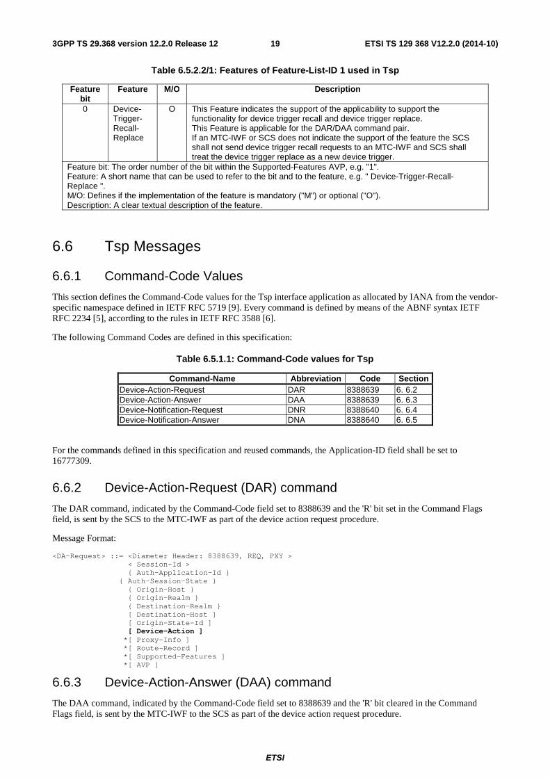
Table 6.5.1.1: Command-Code values for Tsp
Command-Name Abbreviation Code Section Device-Action-Request DAR 8388639 6. 6.2 Device-Action-Answer DAA 8388639 6. 6.3 Device-Notification-Request DNR 8388640 6. 6.4 Device-Notification-Answer DNA 8388640 6. 6.5
For the commands defined in this specification and reused commands, the Application-ID field shall be set to 16777309.
6.6.2 Device-Action-Request (DAR) command
The DAR command, indicated by the Command-Code field set to 8388639 and the 'R' bit set in the Command Flags field, is sent by the SCS to the MTC-IWF as part of the device action request procedure.
Message Format:
<DA-Request> ::= <Diameter Header: 8388639, REQ, PXY > < Session-Id > { Auth-Application-Id } { Auth-Session-State } { Origin-Host } { Origin-Realm } { Destination-Realm } [ Destination-Host ] [ Origin-State-Id ] [ Device-Action ] *[ Proxy-Info ] *[ Route-Record ] *[ Supported-Features ] *[ AVP ]
6.6.3 Device-Action-Answer (DAA) command
The DAA command, indicated by the Command-Code field set to 8388639 and the 'R' bit cleared in the Command Flags field, is sent by the MTC-IWF to the SCS as part of the device action request procedure.

ETSI
ETSI TS 129 368 V12.2.0 (2014-10)203GPP TS 29.368 version 12.2.0 Release 12
Message Format:
<DA-Answer> ::= < Diameter Header: 8388639, PXY > < Session-Id > { Auth-Application-Id } { Auth-Session-State } { Origin-Host } { Origin-Realm } [ Result-Code ] [ Experimental-Result ] [ Error-Message ] [ Error-Reporting-Host ] *[ Failed-AVP ] [ Origin-State-Id ] { Device-Notification } *[ Redirect-Host ] [ Redirect-Host-Usage ] [ Redirect-Max-Cache-Time ] *[ Proxy-Info ] *[ Supported-Features ] *[ AVP ]
6.6.4 Device-Notification-Request (DNR) command
The DNR command, indicated by the Command-Code field set to 8388640 and the 'R' bit set in the Command Flags field, is sent by the MTC-IWF to the SCS as part of the device notification report procedure.
Message Format:
<DN-Request> ::= < Diameter Header: 8388640, REQ, PXY > < Session-Id > { Auth-Application-Id } { Auth-Session-State } { Origin-Host } { Origin-Realm } { Destination-Realm } { Destination-Host } [ Origin-State-Id ] [ Device-Notification ] *[ Proxy-Info ] *[ Route-Record ] *[ AVP ]
6.6.5 Device-Notification-Answer (DNA) command
The DNA command, indicated by the Command-Code field set to 8388640 and the 'R' bit cleared in the Command Flags field, is sent by the SCS to the MTC-IWF as part of the device notification report procedure.
Message Format:
<DN-Answer> ::= < Diameter Header: 8388640, PXY > < Session-Id > { Auth-Application-Id } { Auth-Session-State } { Origin-Host } { Origin-Realm } [ Result-Code ] [ Experimental-Result ] [ Origin-State-Id ] [ Error-Message ] [ Error-Reporting-Host ] *[ Redirect-Host ] [ Redirect-Host-Usage ] [ Redirect-Max-Cache-Time ] *[ Failed-AVP ] *[ Proxy-Info ] *[ AVP ]
ETSI
ETSI TS 129 368 V12.2.0 (2014-10)213GPP TS 29.368 version 12.2.0 Release 12
Annex A (informative): Tsp Message Flows
A.1 General This Annex illustrates Tsp Message Flows.
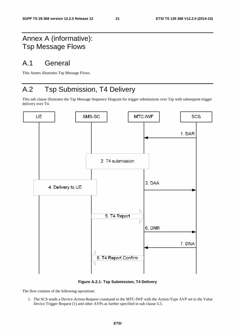
A.2 Tsp Submission, T4 Delivery This sub clause illustrates the Tsp Message Sequence Diagram for trigger submissions over Tsp with subsequent trigger delivery over T4.
Figure A.2.1: Tsp Submission, T4 Delivery
The flow consists of the following operations:
1. The SCS sends a Device-Action-Request command to the MTC-IWF with the Action-Type AVP set to the Value Device Trigger Request (1) and other AVPs as further specified in sub clause 5.5.
ETSI
ETSI TS 129 368 V12.2.0 (2014-10)223GPP TS 29.368 version 12.2.0 Release 12
2. The MTC-IWF selects T4 for delivery performs the T4 submission procedures and is informed of the submission outcome.
3. The MTC-IWF confirms the status of the device trigger request to the SCS by sending a Device-Action-Answer command with the Action-Type AVP set to the Value Device Trigger Request (1) and the Request-Status AVP set to value indicating the status of the device trigger request. Other AVPs as further specified in sub clause 5.5.
4. - 5. The SMS-SC performs delivery procedures and reports the outcome to the MTC-IWF.
6. The MTC-IWF notifies the SCS of the outcome of the device trigger request by sending a Device-Notification-Request command with Action-Type AVP set to the value Delivery Report (2), the Delivery-Outcome AVP set to the proper value.
7. The SCS acknowledges to the MTC-IWF that is has successfully received the out come of the device trigger request by sending a Device-Notification-Answer command with Action-Type AVP set to the value Delivery Report (2).
8. The MTC-IWF responds back to the SMS-SC that is has successfully transferred the report.
NOTE: A SMS-SC will repeat the procedure from steps 5 to ensure the Deliver Report is received if a negative confirmation is received.
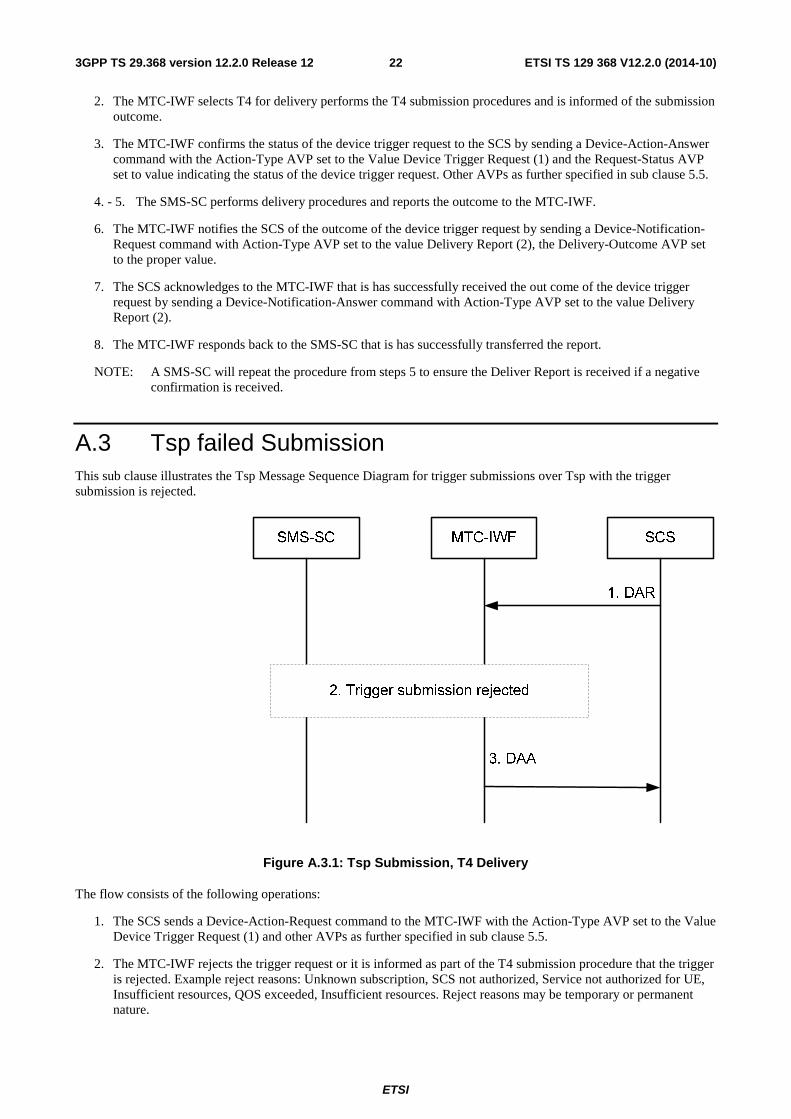
A.3 Tsp failed Submission This sub clause illustrates the Tsp Message Sequence Diagram for trigger submissions over Tsp with the trigger submission is rejected.
Figure A.3.1: Tsp Submission, T4 Delivery
The flow consists of the following operations:
1. The SCS sends a Device-Action-Request command to the MTC-IWF with the Action-Type AVP set to the Value Device Trigger Request (1) and other AVPs as further specified in sub clause 5.5.
2. The MTC-IWF rejects the trigger request or it is informed as part of the T4 submission procedure that the trigger is rejected. Example reject reasons: Unknown subscription, SCS not authorized, Service not authorized for UE, Insufficient resources, QOS exceeded, Insufficient resources. Reject reasons may be temporary or permanent nature.

ETSI
ETSI TS 129 368 V12.2.0 (2014-10)233GPP TS 29.368 version 12.2.0 Release 12
3. The MTC-IWF informs the SCS of the device trigger request outcome by sending a Device-Action-Answer command with the Action-Type AVP set to the Value Device Trigger Request (1) and the Request-Status AVP set to an appropriate error value indicating the rejection of the device trigger request. Other AVPs as further specified in sub clause 5.5. The device trigger request has reached a final status at this point and the procedure ends here.
A.4 Tsp Submission, Failed T4 Delivery This sub clause illustrates the Tsp Message Sequence Diagram for trigger submissions over Tsp with subsequent a failed trigger delivery over T4.
Figure A.4.1: Tsp Submission, T4 Delivery
The flow consists of the following operations:
1. The SCS sends a Device-Action-Request command to the MTC-IWF with the Action-Type AVP set to the Value Device Trigger Request (1) and other AVPs as further specified in sub clause 5.5.
2. The MTC-IWF selects T4 for delivery performs the T4 submission procedures and is informed of a positive submission outcome.
3. The MTC-IWF confirms the status of the device trigger request to the SCS by sending a Device-Action-Answer command with the Action-Type AVP set to the Value Device Trigger Request (1) and the Request-Status AVP

ETSI
ETSI TS 129 368 V12.2.0 (2014-10)243GPP TS 29.368 version 12.2.0 Release 12
set to value indicating the SUCCESS status of the device trigger request. Other AVPs as further specified in sub clause 5.5.
4 - 5. The SMS-SC concludes after one or more retries that the triger is not deliverable to the UE (i.e trigger validity period exceeded, persistent error received from HSS, UE or network) and reports the outcome to the MTC-IWF.
6. The MTC-IWF notifies the SCS of the negative outcome of the device trigger request by sending a Device-Notification-Request command with Action-Type AVP set to the value Delivery Report (2), the Delivery-Outcome AVP set to the appropriate error value. Delivery errors may be of temporary or permanent nature.
7. The SCS acknowledges to the MTC-IWF that is has received the out come of the device trigger request by sending a Device-Notification-Answer command with Action-Type AVP set to the value Delivery Report (2).
8. The MTC-IWF responds back to the SMS-SC that is has successfully transferred the report.
NOTE: A SMS-SC will repeat the procedure from steps 5 to ensure the Deliver Report is received if a negative confirmation is received.
A.5 Tsp Recall Submission, Recall Success This subclause illustrates the message signalling flow for trigger recall submissions over Tsp with recall success over T4.
Figure A.5.1: Tsp Recall Submission, T4 Recall Success
The signalling flow consists of the following operations:
1. The SCS sends a Device-Action-Request command to the MTC-IWF with the Action-Type AVP set to the Value Device Trigger Recall Request (3) and reference-number for the trigger to be recalled and other AVPs as further specified in subclause 5.7.
2. The MTC-IWF selects T4 for trigger recall and performs the T4 recall procedures and is informed of the trigger recall outcome.
3. MTC-IWF sends Device-Action-Answer command to SCS with the Action-Type AVP set to the Value Device Trigger Recall Request (3) and the Request-Status AVP set to value indicating SUCCESS. Other AVPs as further specified in subclause 5.7.

ETSI
ETSI TS 129 368 V12.2.0 (2014-10)253GPP TS 29.368 version 12.2.0 Release 12
A.6 Tsp Recall Submission, Recall Failure This subclause illustrates the message signalling flow for trigger recall submissions over Tsp with recall failure over T4.
Figure A.6.1: Tsp Recall Submission, T4 Recall Failure
The signalling flow consists of the following operations:
1. The SCS sends a Device-Action-Request command to the MTC-IWF with the Action-Type AVP set to the Value Device Trigger Recall Request (3) and reference-number for the trigger to be recalled and other AVPs as further specified in subclause 5.7.
2. The MTC-IWF rejects the trigger recall request or it is informed as a part of the T4 recall procedure that the trigger recall is rejected.
3. MTC-IWF sends Device-Action-Answer command to SCS with the Action-Type AVP set to the Value Device Trigger Recall Request (3) and the Request-Status AVP set to value indicating applicable reason for the recall failure, see subclause 6.4.9. Other AVPs as further specified in subclause 5.7.
4. The SMS-SC reports the delivery outcome for the original trigger message to the MTC-IWF according to A.2, step 5 to 8 for successful case and A.4, step 5 to 8 for unsuccessful case.
A.7 Tsp Replace Submission, Replace Success This subclause illustrates the message signalling flow for trigger replace submissions over Tsp with replace success over T4.

ETSI
ETSI TS 129 368 V12.2.0 (2014-10)263GPP TS 29.368 version 12.2.0 Release 12
Figure A.7.1: Tsp Replace Submission, T4 Replace Success
The signalling flow consists of the following operations:
1. The SCS sends a Device-Action-Request command to the MTC-IWF with the Action-Type AVP set to the Value Device Trigger Replace Request (4) and old-reference-number for the trigger to be replaced. The new trigger reference number is assigned by the SCS to the newly submitted trigger message. Other AVPs as further specified in subclause 5.8.
2. The MTC-IWF selects T4 for trigger replace and performs the T4 replace procedures and is informed of the trigger replace outcome.
3. MTC-IWF sends Device-Action-Answer command to SCS with the Action-Type AVP set to the Value Device Trigger Replace Request (4) and the Request-Status AVP set to value indicating SUCCESS. Other AVPs as further specified in subclause 5.8.
4. The SMS-SC will attempt to deliver the new trigger. This step can happen anytime after step 2.
5. The SMS-SC reports the delivery outcome for the new trigger message to the MTC-IWF according to A.2, step 5 to 8 for successful case and A.4, step 5 to 8 for unsuccessful case.
A.8 Tsp Replace Submission, Replace Failure This subclause illustrates the message signalling flow for trigger replace submissions over Tsp with replace failure over T4.

ETSI
ETSI TS 129 368 V12.2.0 (2014-10)273GPP TS 29.368 version 12.2.0 Release 12
SMS-SC MTC-IWFUE SCS
1. Device-Action-Request
3. Device-Action-Answer
Action Type = Device trigger replace
2. T4 replace failure
Delivery of old trigger
5. Delivery of new trigger
6. Delivery report for new trigger
4. Delivery report for old trigger
Figure A.8.1: Tsp Replace Submission, T4 Replace Failure
The signalling flow consists of the following operations:
1. The SCS sends a Device-Action-Request command to the MTC-IWF with the Action-Type AVP set to the Value Device Trigger Replace Request (4) and old-reference-number for the trigger to be replaced. Other AVPs as further specified in subclause 5.8.
2. The MTC-IWF rejects the trigger replace request or it is informed as a part of the T4 replace procedure that the trigger replace is rejected.3. MTC-IWF sends Device-Action-Answer command to SCS with the Action-Type AVP set to the Value Device Trigger Replace Request (4) and the Request-Status AVP set to value indicating applicable reason for the replace failure, see subclause 6.4.9 . Other AVPs as further specified in subclause 5.8.
4. The SMS-SC reports the delivery outcome for the original trigger message to the MTC-IWF according to A.2, step 5 to 8 for successful case and A.4, step 5 to 8 for unsuccessful case. Procedures ends if the Request-Status AVP value in step 3 was different from ORIGINALMESSAGESENT (112).
5. If the Request-Status AVP value in step 3 was ORIGINALMESSAGESENT (112), the SMS-SC will attempt to deliver the new trigger. This step can happen anytime after step 2.
6. The SMS-SC reports the delivery outcome for the new trigger message to the MTC-IWF according to A.2, step 5 to 8 for successful case and A.4, step 5 to 8 for unsuccessful case.

ETSI
ETSI TS 129 368 V12.2.0 (2014-10)283GPP TS 29.368 version 12.2.0 Release 12
Annex B (informative): Change history
Change history Date TSG # TSG Doc. CR Rev Subject/Comment Old New
2012-05 CT3#69 C3-121282 Initial verson includes agreed documents C3-120719, C3-121110, C3-121112, C3-121114, C3-121234, C3-121238, C3-121239, C3-121240, C3-121242, C3-121278 and C3-121279.
0.0.0 0.1.0
2012-06 CP#56 CP-120361 Editorial update by MCC for presentation to TSG CT for information.
0.1.0 1.0.0
2012-08 CT3#70 C3-121763 Version includes agreed documents C3-121380, C3-121382, C3-121384, C3-121385, C3-121560, C3-121561, C3-121563, C3-121564, C3-121573, C3-121574, C3-121598 and C3-121725
1.0.0 1.1.0
2012-09 CP#57 CP-120546 Editorial update by MCC for presentation to TSG CT for approval
1.1.0 2.0.0
2012-09 CP#57 Rel-11 was produced by MCC after TSG CT's approval 2.0.0 11.0.0 2012-12 CP#58 CP-120836 001 1 Assignment of allocated Diameter code values 11.0.0 11.1.0 2012-12 CP#58 CP-120836 003 3 Correction of MTC-IWF checks on quota and rate of
device triggers from SCS 11.0.0 11.1.0
2012-12 CP#58 CP-120836 004 Removal of empty clauses 11.0.0 11.1.0 2013-03 CP#59 CP-130076 005 2 Application Port identifier over Tsp interface 11.1.0 11.2.0 2013-06 CP#60 CP-130327 008 1 Additional value for outcome of device trigger 11.2.0 11.3.0 2013-09 CP#61 CP-130550 009 Correction of Application-Port-Identifier AVP type 11.3.0 11.4.0 2014-03 CP#63 CP-140092 010 3 Protocol enhancements for the support of device recall
and replace procedure 11.4.0 12.0.0
2014-03 CP#63 CP-140092 011 2 Introduction of device trigger recall/replace functions 11.4.0 12.0.0 06/2014 TSG#64 CP-140392 0014 - Clarification on bitmask 12.0.0 12.1.0 06/2014 TSG#64 CP-140392 0012 3 Corrections to trigger recall and replace procedures 12.0.0 12.1.0 09/2014 CT-65 CP-140540 0015 - Error handling, MTC error diagnostic 12.1.0 12.2.0

ETSI
ETSI TS 129 368 V12.2.0 (2014-10)293GPP TS 29.368 version 12.2.0 Release 12
History
Document history
V12.2.0 October 2014 Publication