Embed Size (px)
Citation preview

UN
CO
NTR
OLL
ED IF
PR
INTE
D
ELECTRICAL AND MECHANICAL ENGINEERING INSTRUCTIONS
VEHICLE D 322 Issue 3, Apr 11
1
TRUCK, WRECKER, HEAVY, MC3, 8 TONNE (MACK), ARMY (AUST) 6778
NSN 2320-66-151-7176
TECHNICAL DESCRIPTION
This instruction is authorised for use by command of the Chief of Army. It provides direction, mandatory controls and procedures for the operation, maintenance and support of equipment. Personnel are to carry out any action required by this instruction in accordance with EMEI General A 001.
TABLE OF CONTENTS
Page No Page No Introduction ................................................................................3 Assocoiated Publications ...........................................................3 Vehicle Systems.........................................................................4
General .............................................................................4 Cooling System......................................................................4
Cooling Fan Hub ...............................................................4 Fuel System...........................................................................4
Fuel Tank ..........................................................................4 Speed Limiter ....................................................................4
Air Cleaners ...........................................................................5 Clutch.....................................................................................6 Transmission .........................................................................6
Range Shift Air System — All Models...............................8 Drive Lines ........................................................................9
Transfer Case Oil Cooler .......................................................9 Heat Exchanger ..............................................................10 Circulation Pump Assembly ............................................11 Suction Case Assembly ..................................................12 Power Steering Pump .....................................................12 Priority Valve Operation ..................................................13 Electrical Components ....................................................14
Drive Shafts .........................................................................14 Vehicle Cabin.......................................................................14
Crew Cabin .....................................................................14 Audio System ..................................................................15
Suspension ..........................................................................15 Vehicle Control Systems......................................................16
Dash Instruments ............................................................16 Electrical System .................................................................16 Closed Circuit Television .....................................................17 Communication Systems .....................................................17
Radio Antenna Mountings...............................................17 Radio Mounting ...............................................................17 Radio Amplifier................................................................17 Radio Cabling..................................................................17
Recovery System.................................................................17 Introduction .....................................................................17 Frame Assembly .............................................................18 Tool Bin Assemblies........................................................18 Electrical System.............................................................18 Lighting............................................................................18 Cable Stowage................................................................18
Catwalks ......................................................................... 18 Recovery Equipment ........................................................... 18
Spades............................................................................ 18 Spade Cylinders ............................................................. 19 Winch Rope Sheaves ..................................................... 19 Fairleads ......................................................................... 19 Hydraulic System............................................................ 19 Power Take Offs (PTOs) ................................................ 19 PTO Actuation Systems.................................................. 19 Hydraulic Pumps............................................................. 19 Oil Filters......................................................................... 19 Hydraulic Directional Control Valve Assembly................ 20 Relief Valve..................................................................... 21 Oil Cooler........................................................................ 21 Hydraulic Reservoir and Mountings................................ 21 Towing Hitch Assembly .................................................. 22 Lift Cylinder..................................................................... 22 Cross Bar........................................................................ 22 Towing Attachments ....................................................... 22 Forward Self-recovery System. ...................................... 22 Remote Control System.................................................. 23 Throttle Control ............................................................... 23
Pneumatic System .............................................................. 24 Sepson Winches ................................................................. 25
Winch Assembly ............................................................. 25 Winch Controls .................................................................... 27
Hydraulic Valve Block Assembly .................................... 27 Over Centre Valves ........................................................ 28 Sequence Valve.............................................................. 29 Shuttle Valve................................................................... 29 Electric Operated Pressure Relief Valve ........................ 29 Pressure Reducing Valve ............................................... 30 Pressure Gauge Outlet ................................................... 30 Pressure Transmitters MP3 and MP4............................. 30 Winch Drive Motor Assemblies....................................... 30 Primary Drive Unit Assembly .......................................... 31 Secondary Drive Unit Assemblies .................................. 31 Free Spooling Cylinder ................................................... 32 Free Spooling Device Control Valve............................... 32 Drum Brake..................................................................... 32 Torque Control System................................................... 32 Cable Tensioning System............................................... 33
UN
CO
NTR
OLL
ED IF
PR
INTE
D
VEHICLE D 322 Issue 3, Apr 11
ELECTRICAL AND MECHANICAL ENGINEERING INSTRUCTIONS
2
Steel Wire Rope.............................................................. 33 Palfinger Crane PK 9501..................................................... 34
General ........................................................................... 34 Base................................................................................ 34 Column............................................................................ 34 Inner Boom ..................................................................... 34 Outer Boom..................................................................... 34 Extension Boom.............................................................. 34 Hydraulic System............................................................ 34
Crane Monitoring System............................................... 34 Control Panel.................................................................. 36 CAN Bus System............................................................ 37 Overload Protection........................................................ 37 Control Valve .................................................................. 38 Support Legs .................................................................. 39 Remote Control System ................................................. 39 Emergency Manual Operation........................................ 40
LIST OF FIGURES
Page No Page No Figure 1 Truck, Wrecker, Heavy, MC3, 8 Tonne (Mack),
Army (AUST) 6778........................................................ 3 Figure 2 Speed Limiter Circuit Diagram.................................. 5 Figure 3 Clutch – Exploded View............................................ 6 Figure 4 Eaton Transmission – Top View ............................... 7 Figure 5 Eaton Transmission Auxiliary Box ............................ 7 Figure 6 Transmission Air Lines ............................................. 8 Figure 7 Drive Lines................................................................ 9 Figure 8 Transfer Case Oil Cooler System ........................... 10 Figure 9 Radiator and Heat Exchanger ................................ 11 Figure 10 Circulation Pump Assembly.................................. 11 Figure 11 Suction Case Assembly........................................ 12 Figure 12 Power Steering Pump........................................... 12 Figure 13 Priority Valve Operation........................................ 13 Figure 14 Transfer Case Oil Cooler Wiring Diagram ............ 14 Figure 15 Cabin Sub-Frame ................................................. 15 Figure 16 HRV Dash Panel Layout....................................... 16 Figure 17 Hydraulic System Return Line Filters ................... 20 Figure 18 Hydraulic Control Valve Supply and Return
Lines............................................................................ 20 Figure 19 Towing Hitch ......................................................... 22 Figure 20 Throttle Pneumatic Control Circuit........................ 24 Figure 21 Winch Assembly – Exploded View ....................... 26 Figure 22 Hydraulic Valve Block ........................................... 27 Figure 23 Hydraulic Valve Block Circuit Diagram ................. 28 Figure 24 Over Centre Valves .............................................. 28
Figure 25 Sequence Valve ................................................... 29 Figure 26 Rope Layer Sensor .............................................. 29 Figure 27 Pressure Reducing Valve, Hydraulic Oil
Pressure Measuring Point, MP3 and MP4 Pressure Sensors....................................................................... 30
Figure 28 Winch Drive Gear Units and Free Spooling Cylinder....................................................................... 31
Figure 29 Distance Sensor ................................................... 33 Figure 30 Paltronic System Overview .................................. 35 Figure 31 Paltronic Control Panel......................................... 36 Figure 32 Paltronic Control System Components ................ 36 Figure 33 CAN Bus Cable .................................................... 37 Figure 34 Overload Protection Indicators ............................. 38 Figure 35 Hydraulic Control Valve Interface......................... 38 Figure 36 Support Leg Control Valve and Levers ................ 39 Figure 37 Remote Control Console ...................................... 39 Figure 38 HRV Cabin/Chassis Electrical Circuit Diagram .... 41 Figure 39 Hydraulic Control Valve Schematic Circuit........... 43 Figure 40 Recovery System Main Electrical Circuit.............. 45 Figure 41 Remote Control Electrical Circuit ......................... 47 Figure 42 Recovery System Pneumatic Circuit (New or
Old Diagram?) ............................................................ 49 Figure 43 Hydraulic Control Valve Circuit............................. 51 Figure 44 Slew, Main Boom and Outer Boom Systems ....... 53 Figure 45 Boom Extension Cylinder ..................................... 55 Figure 46 Crane Support Legs ............................................. 57
LIST OF TABLES
Page No Page No Table 1 Paltronic Overload Codes ........................................ 38

UN
CO
NTR
OLL
ED IF
PR
INTE
D
ELECTRICAL AND MECHANICAL ENGINEERING INSTRUCTIONS
VEHICLE D 322 Issue 3, Apr 11
3
INTRODUCTION
1. This EMEI describes the technical system and details of the Truck, Wrecker, Heavy, MC3, 8 Tonne (Mack), Army (Aust) 6778 (HRV) as shown in Figure 1. All relevant weights, dimensions and performance figures for the vehicle are detailed in the Data Summary, EMEI Vehicle D 320.
Figure 1 Truck, Wrecker, Heavy, MC3, 8 Tonne (Mack), Army (AUST) 6778
2. The HRV is an ‘R’ series Mack 6×6 cabin chassis modified and fitted with a Miller recovery platform. The recovery platform incorporates hydraulically operated spades, under-lift attachment, twin 13 tonne recovery winches and a chassis mounted MHE crane.
ASSOCOIATED PUBLICATIONS
3. Reference may be necessary to the latest issue of the following documents:
a. Australian Army Book – Record Book for Service Equipment – GM 120;
b. Complete Equipment Schedule CCES 19726 – Truck, Wrecker, Heavy, MC3;
c. Complete Equipment Schedule CCES 19727 – Raven Radio Installation Kit;
d. Complete Equipment Schedule SCES 012323 – Recovery Equipment HRV;
e. Complete Equipment Schedule SCES 012318 – Vehicle Accessory Maintenance Kit;
f. Complete Equipment Schedule SCES 13820 – Radio Set UHF 16 Channel 336-400 MHz Handheld Kit for HRV;
g. Defence Road Transport Instructions (DRTI);
h. EMEI Vehicle D 320 – Truck, Wrecker, Heavy, MC3, 8 Tonne (Mack), Army (Aust) 6778 – Data Summary;
i. EMEI Vehicle D 323 – Truck, Wrecker, Heavy, MC3, 8 Tonne (Mack), Army (Aust) 6778 – Light Grade Repair;
j. EMEI Vehicle D 324-1 – Truck, Wrecker, Heavy, MC3, 8 Tonne (Mack), Army (Aust) 6778 – Medium Grade Repair;

UN
CO
NTR
OLL
ED IF
PR
INTE
D
VEHICLE D 322 Issue 3, Apr 11
ELECTRICAL AND MECHANICAL ENGINEERING INSTRUCTIONS
4
k. EMEI Vehicle D 324-2 – Truck, Wrecker, Heavy, MC3, 8 Tonne (Mack), Army (Aust) 6778 – Heavy Grade Repair;
l. EMEI Vehicle D 329 – Truck, Wrecker, Heavy, MC3, 8 Tonne (Mack), Army (Aust) 6778 – Servicing Instruction;
m. EMEI Vehicle D 329-1 – Truck, Wrecker, Heavy, MC3, 8 Tonne (Mack), Army (Aust) 6778 – Servicing/Inspection of CES;
n. Repair Parts Scale (RPS) 02252;
o. Current version of the Technical Regulation of Army Materiel Manual (TRAMM) (available from DTR-A website http://intranet.defence.gov.au/armyweb/Sites/DTRA); and
p. User Handbook for Single Channel Radio System RAVEN B Vehicle and Ground Installations.
VEHICLE SYSTEMS
General
4. This section deals with the variations from the standard Truck, Cargo, Heavy, 8 Tonne, Mack. The existing cabin chassis has been modified to suit the role with the major modifications being detailed below.
COOLING SYSTEM
Cooling Fan Hub
5. The engine has been fitted with a viscous fan hub. The fan drive clutch is a fluid coupling containing silicone oil. Fan speed is regulated by the torque carrying capacity of silicone oil. A heat-sensitive, bi-metal spring connected to an opening plate regulates the amount of silicone oil entering the coupling. Fan speed increases with a rise in temperature and decreases as temperature goes down. The more silicone oil in the coupling, the greater the fan speed. The less silicone oil, the slower the fan speed.
FUEL SYSTEM
6. The governor of the fuel injection pump has been modified from the standard Truck, Cargo, Heavy, 8 Tonne, Mack pump to provide the additional engine output required for this application. The effects of the modification are to increase the overall power of the engine from 211 kW to 238 kW at 2 100 r/min and shift the engine operating range from 1 200 – 2 100 r/min to 1 300 – 2 100 r/min.
7. The components replaced are:
a. hanger stop plate, # FA79PL400285;
b. adjustable stop plate, # FA79PL403706; and
c. droop screw, # FA79SC400142.
Fuel Tank
8. The fuel tank for the vehicle is mounted between the vehicle chassis rails and protrudes into the area in the centre of the recovery system, immediately forward of the winches. The fuel tank capacity is 498 litres. In all other respects, the fuel system is as fitted to the Truck, Cargo, Heavy, 8 Tonne, Mack.
Speed Limiter
9. A speed limiter has been incorporated into the vehicle control system to limit the speed of the vehicle to 102 km/h on level roads without the influence of wind.
10. The speed limiter consists of the following components:
a. Electronic Control Unit. The Electronic Control Unit (ECU) manages the speed limiter, receiving input from the transducer and providing proportional electrical signals to the solenoid valve.
b. Transducer. The transducer is a rotary signal device fitted between the speedometer cable and the speedometer to measure the speed of the vehicle. The transducer provides a pulsating signal to the ECU at the rate of 5 000/kilometre.

UN
CO
NTR
OLL
ED IF
PR
INTE
D
ELECTRICAL AND MECHANICAL ENGINEERING INSTRUCTIONS
VEHICLE D 322 Issue 3, Apr 11
5
c. Solenoid Valve. The solenoid valve is fitted into the airline between the accelerator pedal and the fuel injection pump. The solenoid valve receives an electrical signal from the ECU whenever the speed exceeds 102 km/h. Activation of the solenoid valve cuts the air supply from the accelerator pedal to the throttle control, hence, reducing the fuel supply to the engine. Once the speed has dropped below 102 km/h, the electrical signal from the ECU ceases, the solenoid valve once again directs air from the accelerator pedal to the fuel injection pump throttle control.
11. The connection and circuit diagram for the speed limiter are shown in Figure 2.
Figure 2 Speed Limiter Circuit Diagram
AIR CLEANERS
12. The vehicle has been fitted with Donaldson 11 inch air cleaners.

UN
CO
NTR
OLL
ED IF
PR
INTE
D
VEHICLE D 322 Issue 3, Apr 11
ELECTRICAL AND MECHANICAL ENGINEERING INSTRUCTIONS
6
CLUTCH
13. The clutch fitted to the HRV is an Eaton Solo 15.50 inch, heavy duty, 2 800 lb, dual plate clutch (Figure 3). This clutch has a lower clamping pressure than that of the standard Mack 8 tonne vehicle range.
1 Snap ring 6 Clutch disc 11 Thrust washer 2 Washer 7 Hollow pin 12 Spring washer 3 Pressure plate and housing 8 Clutch brake 13 Mounting bolt 4 Clutch disc 9 Release bearing 5 Intermediate plate 10 Clutch release bearing sleeve
Figure 3 Clutch – Exploded View
TRANSMISSION
14. The transmission fitted to the vehicle is an Eaton Model RTX 14710B ten-speed, non-selective, non-synchromesh, Roadranger transmission of which the speed ranges are obtained from a five-speed gearbox with high and low ranges obtained from an auxiliary box incorporated into the rear of the transmission housing. The first five gear ratios are obtained whilst the auxiliary box is in low range and the higher speeds are obtained by shifting to high range.
1 2
3
4
5
6
7
8
9
10
11 12
13

UN
CO
NTR
OLL
ED IF
PR
INTE
D
ELECTRICAL AND MECHANICAL ENGINEERING INSTRUCTIONS
VEHICLE D 322 Issue 3, Apr 11
7
15. A view of the transmission is shown in Figure 4 and the auxiliary box components are shown in Figure 5.
Figure 4 Eaton Transmission – Top View
Figure 5 Eaton Transmission Auxiliary Box
HIGH/LOW AUXILIARY
BOX REVERSE IDLERS
COUNTERSHAFTS MAINSHAFT
HIGH RANGE CLUTCH
SYNCHRO UNIT
LOW RANGE GEAR
COUNTERSHAFTS

UN
CO
NTR
OLL
ED IF
PR
INTE
D
VEHICLE D 322 Issue 3, Apr 11
ELECTRICAL AND MECHANICAL ENGINEERING INSTRUCTIONS
8
16. The transmission incorporates dual cluster shafts and gear sets that are in constant mesh with the gears fitted to a floating main shaft. This constant meshing of gears removes the need to shift gears in and out of mesh, reducing the risk of gear tooth damage. Engagement of each gear is achieved through the use of sliding dog clutches located on the main shaft. These dog clutches are splined to the main shaft and are externally toothed to allow them to engage in corresponding internal toothed portions of the five speed gears.
17. Selection of the five gear speed ratios are made by the driver using the gear shift lever whilst the shift from low to high range and vice versa is achieved through the use of an air shift cylinder fitted to the high/low range shift mechanism. The high/low range shift cylinder is controlled by an air valve located on the gear shift lever.
18. The auxiliary box shift mechanism has a synchromesh unit, that provides a smooth change between high and low range.
19. The transmission is designed to accept two Power Take Off (PTO) drive units. Both these are utilised to drive hydraulic pumps for the recovery system and the crane. The upper right-hand countershaft is fitted with a 47-tooth PTO drive gear to suit a six-bolt PTO, whilst the lower left-hand countershaft is fitted with a 45-tooth PTO drive gear suited to an eight bolt PTO.
20. Optional fittings for the transmission in this application are the inclusion of a forward-mount top cover and a mid-height gear shift tower.
Range Shift Air System — All Models
21. Operation. The Range Shift Air System (Figure 7) consists of the air filter/regulator, slave valve, a range valve or roadranger valve, range cylinder, fittings and connecting air lines.
Figure 6 Transmission Air Lines
22. Constant air from the air filter/regulator is supplied to the ‘S’ or supply port of slave valve and passed through to the inlet or ‘S’ port of range valve.
23. While in LO range, the range valve is open and air is returned to slave valve at the ‘P’ or end port. This signals the valve to supply air in line between the LO range or ‘L’ Port of slave valve and the LO range port of range cylinder housing. Air received at this port moves the range piston to the rear and causes the auxiliary LO range gear to become engaged.
END PORT
HI RANGE SUPPLY
H
P
S
L
SUPPLY FROM VEHICLE
LO RANGE SUPPLY

UN
CO
NTR
OLL
ED IF
PR
INTE
D
ELECTRICAL AND MECHANICAL ENGINEERING INSTRUCTIONS
VEHICLE D 322 Issue 3, Apr 11
9
24. While in HI range, the range valve is closed and no air is returned to the slave valve. This signals the slave valve to supply air in line between the HI range or ‘H’ port of valve and the HI range port of range cylinder cover. Air received at this port moves the range piston forward to engage the auxiliary drive gear with sliding clutch and bypass the LO range gear set.
25. Range shifts can be made only when the gear shift lever is in or passing through neutral. Thus, the range desired can be preselected while the shift lever is in a gear position. As the lever is moved through neutral, the actuating plunger in the shift bar housing releases the slave valve piston, allowing it to move to the selected range position.
Drive Lines
26. The respective speed gears are shown in Figure 7.
Figure 7 Drive Lines
TRANSFER CASE OIL COOLER
27. The transfer case oil cooler system consists of the following major components:
a. heat exchanger,
b. circulation pump assembly,
c. suction case assembly,
d. power steering pump,
e. priority valve, and
f. electrical components.
REVERSE
FIRST
SECONDFIFTH
(OVERDRIVE)
THIRD
FOURTH (DIRECT DRIVE)

UN
CO
NTR
OLL
ED IF
PR
INTE
D
VEHICLE D 322 Issue 3, Apr 11
ELECTRICAL AND MECHANICAL ENGINEERING INSTRUCTIONS
10
28. A diagrammatic representation is shown at Figure 8.
LEGENDSupply
Power Steering Flow
Circulation Unit Motor Flow
Circulation Unit Pump Flow
Figure 8 Transfer Case Oil Cooler System
Heat Exchanger
29. An oil cooler heat exchanger is mounted in front of the engine radiator, below the air conditioning system condenser.

UN
CO
NTR
OLL
ED IF
PR
INTE
D
ELECTRICAL AND MECHANICAL ENGINEERING INSTRUCTIONS
VEHICLE D 322 Issue 3, Apr 11
11
30. The coil and fins of the heat exchanger act as a heat transfer surface, channelling heat from the transfer case oil to the atmosphere thus cooling the oil. The radiator and heat exchanger arrangement is shown in Figure 9.
Figure 9 Radiator and Heat Exchanger
Circulation Pump Assembly
31. The circulation pump assembly (Figure 10) consists of a motor geroter element and a pump geroter element sharing a common drive shaft supported by two long-life lubricated bearings. The motor is driven by oil flow from the truck power steering pump and in turn drives the oil cooler circulation pump.
Figure 10 Circulation Pump Assembly
32. The self-priming pump draws oil through the suction case assembly, passing it through the spin-on filter. The filtered oil then flows to the heat exchanger where it is cooled by the air flow. Cooled oil is then returned to the transfer case via the rear bearing housing.
33. Two high-temperature, long-life Teflon seals act on hardened and ground seal journals of the drive shaft. These individual seals protect against cross contamination of the motor drive and circulation pump oil. Slippage oil

UN
CO
NTR
OLL
ED IF
PR
INTE
D
VEHICLE D 322 Issue 3, Apr 11
ELECTRICAL AND MECHANICAL ENGINEERING INSTRUCTIONS
12
from the pump is internally drained to the pump inlet. Slippage oil from the motor is externally drained and is connected back to the power steering pump inlet.
34. The geroters are keyed to the heavy-duty drive shaft and run on pressure-balanced thrust plates against the main housing. Timing grooves ensure quiet, smooth and pulse-free operation on both the pump and motor.
35. A spin-on type filter is fitted to the circulation pump assembly. The filter is fitted with an inbuilt bypass check valve to allow the oil to bypass the filter element when it is clogged or when the oil viscosity is high.
36. The housing incorporates all cross connections and the following:
a. motor relief valve,
b. pump relief valve,
c. auto start valve,
d. pump filter, and
e. pump and motor connections.
37. A 10.30 kPa reverse sealed check valve is fitted to the housing to protect the shaft from environmental attack. The shaft area is packed with grease as an additional protection against environmental attack.
Suction Case Assembly
38. The suction case assembly (Figure 11) is mounted to the right-hand side of the transfer case and consists of a pickup tube, oil strainer, filler plug and dip stick assembly.
Figure 11 Suction Case Assembly
Power Steering Pump
39. The power steering pump (Figure 12) is coupled to the rear of the compressor and is driven by the compressor crankshaft.
Figure 12 Power Steering Pump

UN
CO
NTR
OLL
ED IF
PR
INTE
D
ELECTRICAL AND MECHANICAL ENGINEERING INSTRUCTIONS
VEHICLE D 322 Issue 3, Apr 11
13
40. The power steering pump is fitted with a priority valve that enables two hydraulic circuits to be fed by the pump. The first circuit supplies oil pressure to the power steering system and the other supplies oil pressure to the transfer case oil cooler system. Flow to the transfer case oil cooler system is determined by pump delivery.
41. The priority valve maintains a constant flow to the power steering circuit and diverts the remaining flow to the transfer case oil cooler circuit to drive the circulation unit motor.
42. The power steering circuit is protected by an integral relief valve in the power steering pump and the transfer case oil cooler circuit is protected by a relief valve fitted to the circulation unit.
Priority Valve Operation
43. The priority valve is shown in Figure 13. Pressure is sensed in cavities ‘A’, ‘B’ and ‘C’. Primary flow into cavity ‘A’ is restricted by the controlled flow orifice. Secondary flow will be zero until the pump flow rate through the controlled flow orifice develops a pressure differential across the control spool.
Figure 13 Priority Valve Operation
44. When pump delivery is increased, pressure builds up in cavities ‘B’ and ‘C’ because of the resistance to flow through the controlled flow orifice. This causes the spool to shift toward cavity ‘A’ against the spring. The amount of spool shift is proportional to the pressure differential between cavities ‘A’ and ‘C’.
45. Flow from the primary port is held to an almost constant volume, as determined by the controlled flow orifice and the metering action of the control spool at area ‘D’. Flow to the secondary port varies with pump delivery. Metering at ‘E’ diverts excess flow to the secondary port.
46. This single spool design cannot give precisely controlled flow to the primary circuit because of the effects of varying conditions of flow and pressure. For example, if the primary circuit is operating at 1 000 lb/in² and the secondary at 100 lb/in², the spool must be metering at ‘E’. However, if primary pressure is 100 lb/in² and secondary is 1 000 lb/in², the spool must be metering at ‘D’. As the two systems approach the same pressure, the probability of flow fluctuation increases because the spool may shift between these two metering points.

UN
CO
NTR
OLL
ED IF
PR
INTE
D
VEHICLE D 322 Issue 3, Apr 11
ELECTRICAL AND MECHANICAL ENGINEERING INSTRUCTIONS
14
Electrical Components
47. The transfer case oil cooler system (Figure 14) is a hydraulically controlled system, which uses few electrical components. A low oil pressure warning sensor is fitted to the outlet of the heat exchanger to sense system pressure. A dash mounted lamp, controlled by the sensor, indicates low system oil pressure.
24 Volt DC LED (INSTALLED IN TRUCK DASH)
BULKHEADTERMINALJUNCTIONBOARD
5 AMP 3AG INLINE FUSE
4 PSI PRESSURE SWITCH INSTALLEDIN HEAT EXCHANGER IN FRONTOF TRUCK RADIATOR
EARTH TO TRUCKCHASSIS
Figure 14 Transfer Case Oil Cooler Wiring Diagram
DRIVE SHAFTS
48. The drive shaft between the transmission and the transfer case has been modified from the standard Truck, Cargo, Heavy, 8 Tonne, Mack to suit the Eaton transmission.
VEHICLE CABIN
49. The vehicle cabin has been modified from the original Truck, Cargo, Heavy, 8 Tonne, Mack cabin to include a crew cabin at the rear of the vehicle cabin. The vehicle cabin is mounted on a separate sub-frame. The operator and crew cabins have been fitted with sound-proofing materials to reduce noise levels within the cabin.
Crew Cabin
50. A crew cabin is fitted behind the vehicle cabin to provide additional seating for recovery crew as well as storage and mounting for the vehicle radio equipment. The crew cabin is fabricated from aluminium sheeting with sound proofing fitted to the interior.
51. The cabin isolation system consists of:
a. a prefabricated steel sub-frame;
b. an air bag suspension; and
c. a Watts link stabiliser system.
52. Sub-frame. The steel sub-frame (Figure 15) carries both the vehicle and crew cabins, providing the same mounting points for the cabin as used for the standard Truck, Cargo, Heavy, 8 Tonne, Mack. The function of the cabin isolation system is to insulate the vehicle and crew cabins from vibration and to cushion the ride within the cabin.
53. The sub-frame is mounted to the vehicle chassis at the front of the frame by fixed pivot points and by air bags at the rear. The fixed pivot points provide positive location of the sub-frame to the vehicle chassis while the air bags provide the required cushioning effect. Shock absorbers fitted in conjunction with the air bags provide a dampening effect to the movement between the vehicle chassis and the cabin sub-frame.
54. Suspension. There are two air bags supporting the rear of the cabin sub-frame, one on each side of the vehicle. Inflation of the suspension is controlled by the control valve mounted on the right-hand rear corner of the sub-frame.

UN
CO
NTR
OLL
ED IF
PR
INTE
D
ELECTRICAL AND MECHANICAL ENGINEERING INSTRUCTIONS
VEHICLE D 322 Issue 3, Apr 11
15
55. The suspension system also incorporates six shock absorbers, one mounted on each corner of the sub-frame and the two co-located with each air bag. The shock absorbers dampen movement of the cabin and sub-frame structure improving ride and driver comfort.
Figure 15 Cabin Sub-Frame
56. Watts Link. The watts link stabiliser is provided to control the lateral movement of the cabin so as to maintain correct alignment with the centre line of the vehicle chassis and reduce excessive ‘body roll’ to the cabin. The watts links is mounted at the rear of the sub-frame, beneath the crew cabin.
Audio System
57. A radio tuner and compact disc player is fitted in the left-hand dash panel. The compact disc player is suitable for playing 12 cm and 8 cm discs only. Two speakers are mounted in the upper rear corners of the vehicle cabin.
SUSPENSION
58. The suspension of the vehicle is the same type and configuration as the standard Truck, Cargo, Heavy, 8 Tonne, Mack with the exception of the bumper pads fitted to both the front and rear suspension.
AIR SUSPENSION
SUB FRAME
WATTS LINK

UN
CO
NTR
OLL
ED IF
PR
INTE
D
VEHICLE D 322 Issue 3, Apr 11
ELECTRICAL AND MECHANICAL ENGINEERING INSTRUCTIONS
16
VEHICLE CONTROL SYSTEMS
Dash Instruments
59. The vehicle uses the same instruments and control systems as the standard Mack ‘R’ model, however, the instrument panel has been rearranged in order to incorporate additional features for the recovery system. The revised dash/instrument panel layout is illustrated in Figure 16.
MITSUBISHI
AUTONORMAL
EXT.BRIGHT CONTRAST
CAM1 / CAM2 CAMERA
SB / ON
CAUTIONDO NOT OPERATE VEHICLE WITHLESS THAN 4.5 X 100 Kpa ORSUSPENSION DAMAGE MAY OCCUR.
1 2 39
12 13 15 17
182228
31 2538
4 14 16
2132
3734
6 1081175
2627 24 1920232935
3033
3639
40
OFF
WARNING
NOT FORPA RK IN G
WORK
BRAKE
ON
Item Description Item Description
1 Map reading lamp 21 Voltmeter 2 Radio/CD player 22 Air horn 3 Air pressure gauge and low air pressure warning lamp 23 Electric horn button 4 Winch control switch 24 Electrical system ignition/ start switch 5 Revolving light switch 25 Engine stop control 6 Fuel gauge 26 Instrument lights (panel) 7 Work light switch 27 Parking brake (emergency stop) 8 Work light ‘ON’ indicator lamp 28 Clearance lights switch 9 Exhaust pyrometer 29 Normal, blackout and reduced lighting switch 10 Driving light switch 30 Dynatard engine brake switch 11 Headlights/park light switch 31 Reserve air supply valve 12 Remote speaker 32 Engine operating instruction plates 13 Tachometer 33 Power divider lock out 14 Emergency/parking brake warning light 34 Transfer case oil warning lamp 15 Speedometer and odometer 35 Drive line warning lamps 16 Oil pressure gauge 36 Hand throttle 17 Coolant temperature gauge 37 Tractor protection valve 18 Engine warning light 38 Windscreen washer switch 19 Air suspension control switch (under right-hand dash
panel behind work brake control) 39 40
Windscreen wiper switch Closed circuit TV monitor
20 Work brake control
Figure 16 HRV Dash Panel Layout
ELECTRICAL SYSTEM
60. The electrical system for the vehicle is essentially the same as the standard Truck, Cargo, Heavy, 8 Tonne, Mack with minor modifications to suit the functions of the recovery vehicle. One of these modifications is the inclusion of a battery isolation switch, which has been mounted to the rear of the battery box. Schematic electrical circuit diagrams for the vehicle cabin/chassis, recovery system and recovery system remote control are shown in Figure 38, Figure 40 and Figure 41 respectively.

UN
CO
NTR
OLL
ED IF
PR
INTE
D
ELECTRICAL AND MECHANICAL ENGINEERING INSTRUCTIONS
VEHICLE D 322 Issue 3, Apr 11
17
CLOSED CIRCUIT TELEVISION
61. The Closed Circuit Television (CCTV) system is to enable the driver to have a clear view of the vehicle towing hitch during recovery tasks. It is not provided as a general rear vision system.
62. The system consists of a 15 cm monochrome monitor mounted in the left-hand instrument panel and two cameras mounted either side on the rear of the recovery vehicle. The monitor is capable of viewing images from one camera at a time, with the required camera selected from the monitor panel.
COMMUNICATION SYSTEMS
63. Allocation for a HF low-powered station and VHF medium-powered station is made in the crew cabin and right-hand rear cabinet. The stations are connected via shielded control cables to an extended front panel situated in the crew cabin. The extended front panel provides mountings for two LSF300 speakers, two MF301 microphones, two CF307 remote channel selectors and a power supply socket. Provision is also made for aerial mountings on the side tool bins.
64. Details of the installation are found in the User Handbook for Single Channel Radio System RAVEN B Vehicle and Ground Installations.
Radio Antenna Mountings
65. Radio antenna mountings are provided on each side at the rear of the recovery system. The right-hand mounting is directly on the upper surface of the storage locker whilst the left-hand mount is fixed to the left-hand spade housing.
Radio Mounting
66. Radio communication system component mountings are provided as follows:
a. in the rear compartment of the right-hand storage locker;
b. in the crew cabin; and
c. in the main cabin, beneath the cabin heater.
67. Hand-held radio mounting is provided on the main cabin.
Radio Amplifier
68. Mountings for the radio amplifier are provided on the right-hand side in the crew cabin.
Radio Cabling
69. Cabling is provided in the vehicle for the radio systems.
RECOVERY SYSTEM
Introduction
70. The recovery system is a dual winch recovery system mounted on a dedicated sub-frame.
71. The recovery system consists of the following sub-systems:
a. two hydraulically operated winches, each limited to a single line pull of 13 tonnes;
b. Palfinger PK 9701 hydraulically operated, truck mounted crane;
c. hydraulic operating system;
d. pneumatic control system;
e. body and frame components; and
f. left- and right-hand tool bin assemblies.

UN
CO
NTR
OLL
ED IF
PR
INTE
D
VEHICLE D 322 Issue 3, Apr 11
ELECTRICAL AND MECHANICAL ENGINEERING INSTRUCTIONS
18
Frame Assembly
72. The rear tailgate and sub-frame assembly are Swedish manufactured ‘Weldon’ steel. This steel does not require any specific welding techniques, however, procedures apply when welding frame components.
Tool Bin Assemblies
73. The tool bin assemblies are prefabricated from aluminium, and are designed to carry the following equipment:
a. recovery CES,
b. the recovery system control systems, and
c. radio equipment.
74. Each storage bin is lined internally with a durable material to prevent the bin base from excessive wear caused by movement of the recovery CES and other components.
Electrical System
75. The recovery system has an integral electrical system connected to the vehicle electrical system by a single connector located at the rear of the crew cabin. The PTO circuit incorporates three relays to prevent power supply to the recovery module unless one or both PTOs are engaged. A circuit diagram of the recovery electrical system is shown at Figure 40.
Lighting
76. The recovery system incorporates the following lighting:
a. White lights are provided in the control cabinets and CES bins for use in non-operational environments.
b. Blue lights are provided in the control cabinets for use under operational (blackout) conditions.
c. Portable work lights for lighting the work area around the vehicle. These are connected to the electrical system via sockets located on each corner of the recovery system.
d. Flood lights with suitable mountings are also provided for fitting into the rotating light mountings.
e. Fixed white lights on the rear to illuminate the work area.
Cable Stowage
77. Stowage facilities are provided for Steel Wire Rope (SWR) on a circular pannier located on the catwalk at the top of the recovery system. The pannier is removable to allow ease of access to the SWR and also to allow access to the recovery system components located below the catwalk.
Catwalks
78. The recovery system is fitted with two separate catwalks. The first covers the forward part of the recovery system whilst the second covers the rear portion of the recovery system.
79. The forward catwalk has hinged sections to allow access to:
a. the hydraulic oil reservoir and cooler, and
b. the fuel filler cap.
80. The rear catwalk has hinged sections to allow access to the winches.
RECOVERY EQUIPMENT
Spades
81. Earth spades are incorporated into the tailgate assembly of the recovery system frame to assist in anchoring the vehicle during recovery operations. The spades are lowered and raised by internal hydraulic cylinders, which are actuated by the main control valve.

UN
CO
NTR
OLL
ED IF
PR
INTE
D
ELECTRICAL AND MECHANICAL ENGINEERING INSTRUCTIONS
VEHICLE D 322 Issue 3, Apr 11
19
Spade Cylinders
82. Each spade is fitted with and actuated by a double acting hydraulic cylinder fitted inside each spade. Each cylinder is operated from the main control valve.
Winch Rope Sheaves
83. The recovery system uses two rope sheaves to reverse the direction of the winch rope. The rope sheaves are mounted in the forward area of the recovery system. Each sheave is allowed to slide on the respective shaft to allow for differing rope paths as the rope is wound onto, or from, the winch drum.
84. Another sheave is mounted on the rear of the tailgate assembly, on the left-hand side, to allow the steel wire rope from the left-hand winch to be redirected to the front of the recovery vehicle, allowing forward, self recovery.
Fairleads
85. A single fairlead is provided for each winch rope in the tailgate assembly to guide the winch rope into, or from, the recovery system during winching operations. The fairleads allow the winch rope to be re-directed to, or from, any angle, to 90° to the centre line of the recovery vehicle.
Hydraulic System
86. The hydraulic system provides power to the following components of the recovery system:
a. winches,
b. crane,
c. spades, and
d. towing hitch.
87. A schematic circuit diagram of the recovery system hydraulic circuit is shown in Figure 39.
Power Take Offs (PTOs)
88. Two PTOs are provided for the operation of the recovery system and are fitted to, and driven by, the vehicle transmission. The left-hand PTO carries and drives a tandem pump, which operates the winches and recovery system hydraulics. The right-hand PTO carries and drives a single pump, which provides oil for the operation of the crane.
PTO Actuation Systems
89. The PTOs are pneumatically actuated by compressed air provided from the vehicle air system. PTO control valves are located at the base of, and to the right of, the driver seat.
Hydraulic Pumps
90. There are three hydraulic pumps fitted to the vehicle transmission to provide hydraulic power to the recovery system.
91. A tandem pump is fitted to the left-hand PTO, the forward pump of these provides hydraulic oil to the P1 inlet of the recovery system hydraulic control valve, whilst the rear pump provides hydraulic oil to the P2 inlet.
92. A single pump is fitted to the right-hand PTO. The purpose of this pump is to provide hydraulic oil to the crane.
93. All three pumps are supplied with hydraulic oil from a common oil reservoir integrated into the recovery system. Oil returning to the hydraulic oil reservoir, from the three circuits, passes through separate return line oil filters. The oil returning from the left-hand winch circuit (P1 inlet) also passes through the oil cooler, before passing through the return line oil filter and, hence, back to the reservoir.
Oil Filters
94. There are three return line filters (Figure 17) fitted into the top of the oil reservoir. These are a replaceable type paper element filter. A hose attached to the base of the filter ensures that the oil is returned to the base of the oil reservoir in order to prevent splashing and aeration of the oil.

UN
CO
NTR
OLL
ED IF
PR
INTE
D
VEHICLE D 322 Issue 3, Apr 11
ELECTRICAL AND MECHANICAL ENGINEERING INSTRUCTIONS
20
Figure 17 Hydraulic System Return Line Filters
Hydraulic Directional Control Valve Assembly
95. The valve is a Parker series P70 open centre directional control valve assembly. The code for the valve assembly is PC70F-07-US15-067-0417892418-001. The valve assembly incorporates a mid-inlet section to allow a second pressure supply line to be connected to the valve, therefore, increasing the flow capacity to the valve. Each inlet port is supplied from the tandem pump driven from the vehicle transmission. The forward pump supplies oil to the end port whilst the rear pump supplies oil to the mid-inlet port (Figure18).
Figure 18 Hydraulic Control Valve Supply and Return Lines
RETURN LINE DIRECT THROUGH OIL FILTER
TO TANK
OIL COOLER
RETURN LINE THROUGH OIL
COOLER TO TANK
HYDRAULIC RESERVOIR

UN
CO
NTR
OLL
ED IF
PR
INTE
D
ELECTRICAL AND MECHANICAL ENGINEERING INSTRUCTIONS
VEHICLE D 322 Issue 3, Apr 11
21
96. Oil supplied to the end port is used to power the left-hand winch and earth spade. Oil supplied to the mid-inlet port is used to power the right-hand winch and earth spade, left and right tow cylinders and lift cylinder. Oil returning from all components is mixed and passes either through the hydraulic oil cooler and return filter or direct through another separate return filter.
Relief Valve
97. There are two pressure relief valves for the hydraulic system. These are both incorporated into the hydraulic control valve assembly. There is one relief valve for each inlet port.
Oil Cooler
98. An oil cooler is fitted to the top of the hydraulic oil reservoir to cool oil returning from R1 of the hydraulic control valve. R1 is the return port for oil returning from the left-hand winch and spade cylinder.
99. The oil cooler is fitted with an electric fan that pulls air up through the oil cooler core to cool the oil.
100. An inlet side pressure relief valve is provided to allow oil to bypass the oil cooler in the event that the oil cooler becomes blocked. This relief valve will open when the return oil pressure at the inlet side of the cooler reaches 2 bar (30 lbf/in²).
101. The maximum operation temperature for the oil cooler is 177°C.
102. Operation of the oil cooler fan is controlled by a thermostat located on the discharge side of the oil cooler, which senses the temperature of the cooled oil. The thermostat is set at 60°C (140°F).
103. The thermostat operation may be overridden by the use of a manual switch located in the recovery system control cabinets.
Hydraulic Reservoir and Mountings
104. The hydraulic oil reservoir is mounted to the centre front of the recovery system and is used to provide oil for the operation of the entire recovery system, including the crane.
105. The reservoir includes the following components:
a. Return Line Oil Filters. Three return line oil filters are provided.
b. Oil Screens. There are three oil screens fitted internally to the oil reservoir, one for each pump supply line.
c. Filler Cap and Breather. The filler cap and breather includes a 10 micron filter screen provided to strain oil when filling the reservoir.
106. The hydraulic reservoir also forms the mounting point for the oil cooler assembly.

UN
CO
NTR
OLL
ED IF
PR
INTE
D
VEHICLE D 322 Issue 3, Apr 11
ELECTRICAL AND MECHANICAL ENGINEERING INSTRUCTIONS
22
Towing Hitch Assembly
107. The towing hitch assembly (Figure 19) consists of three hydraulic cylinders connected to the hitch pivot head that carries the towing cross bar. Two hitch tow cylinders are mounted on the rear cross-member of the vehicle chassis. A hitch lift cylinder is mounted into the upper part of the tailgate assembly.
Figure 19 Towing Hitch
108. The towing cross bar is capable of being fitted with various vehicle adaptors enabling the recovery of different equipment and vehicle types. The adaptors are provided with the recovery system.
Lift Cylinder
109. The lift cylinder is a double acting cylinder with an integrated load holding valve to prevent the load falling in the event of hose or line failure.
Cross Bar
110. The towing cross bar is mounted on the towing hitch pivot head, which comprises a cross bar pivot pin and a fixed pivot head pin. The cross bar is allowed to pivot in the vertical plane on the cross bar pivot pin and in the horizontal plane on the pivot head pin.
Towing Attachments
111. Towing attachments are provided for the following vehicle types:
a. Unimog,
b. ASLAV, and
c. Landrover.
Forward Self-recovery System.
112. Forward self-recovery capability is provided by rear a sheave and rope guide. The rear sheave is fitted to the tailgate below the left-hand winch fairlead.
113. For self-recovery, the rope from the left-hand winch is directed from the fairlead through the self-recovery sheave, through the rope guide and out to the front of the vehicle through the rollers mounted in the front bumper bar.
LIFT CYLINDER
CROSS BAR
TOW CYLINDERS
FORWARD RECOVERY SHEAVE
FAIRLEADS

UN
CO
NTR
OLL
ED IF
PR
INTE
D
ELECTRICAL AND MECHANICAL ENGINEERING INSTRUCTIONS
VEHICLE D 322 Issue 3, Apr 11
23
Remote Control System
114. The recovery system uses a cable/pendant type remote control connected to the recovery system at sockets located in both the left- and right-hand control cabinets.
115. The remote control pendant has switches for all functions of the recovery system, except the crane, and operates on two modes, TOW and RECOVERY. The operating mode is selected by a two-position selector switch located on the remote control pendant.
Throttle Control
116. An engine throttle control system has been incorporated into the recovery system to enable the operator to increase the engine revs to a set limit from the recovery system control panels. A pneumatic switch provides a supply of compressed air from the vehicle air system to actuate the engine throttle control.
117. The compressed air to the throttle control is regulated by a pressure regulator valve, set to provide an engine speed of 1 500 r/min. A double check valve connected between the accelerator pedal and the throttle control system allows the throttle control system to be actuated either by the accelerator pedal or the remote switch located in the control cabinet.
118. A circuit diagram of the throttle pneumatic control system is shown in Figure 20.

UN
CO
NTR
OLL
ED IF
PR
INTE
D
VEHICLE D 322 Issue 3, Apr 11
ELECTRICAL AND MECHANICAL ENGINEERING INSTRUCTIONS
24
Figure 20 Throttle Pneumatic Control Circuit
PNEUMATIC SYSTEM
119. The recovery system pneumatic system receives compressed air from the HRV vehicle air system via the air distribution manifold fitted to the first crossmember. The pneumatic system is illustrated in Figure 42.

UN
CO
NTR
OLL
ED IF
PR
INTE
D
ELECTRICAL AND MECHANICAL ENGINEERING INSTRUCTIONS
VEHICLE D 322 Issue 3, Apr 11
25
SEPSON WINCHES
Winch Assembly
120. The winches incorporated into the recovery system are a single drum, two speed, with constant line pull, capable of manual or automatic operation, via a Programmable Logic Controller (PLC). When in automatic mode, the winches have a constant line pull of 13 tonne, and a maximum line pull of 13 tonne on the first layer of the drum when operating in manual mode. The winches incorporate the following features:
a. Cable Drum. The cable drum is mounted in a dedicated frame assembly.
b. Planetary Drive Gears. The planetary gear train provides maximum drive reduction for the winch.
c. Hydraulic Motors. There are three hydraulic motors fitted to each winch. The motors are operated in sequence to provide high-speed, low-torque or low-speed, high-torque drive depending on the load being recovered.
d. Drive Gear Units. The drive gear units transfer the drive from the hydraulic motors to the winch drive gear. The primary drive gear is a fixed drive whilst the secondary drive gears are free-wheeling units.
e. Hydraulic Brake. The hydraulic brake is a fail-safe device that prevents rotation of the winch drum when not under power or in the event of a hydraulic line failure. The brake is released whenever hydraulic power is applied to the winch motors. This brake does not prevent rotation of the drum if the free spooling device is disengaged.
f. Free Spooling Device. The free spooling device is a pneumatic operated plunger that locks the annulus of the planetary gear train when drive is required to the winch. Retracting the free spooling device allows the planetary gear train and the winch drum to rotate freely.
g. Pressure Roller and Distance Sensor. The pressure roller indicates the numbers of rope layers wound onto the winch drum and positions the sensor arm accordingly. The position of the sensor arm is detected by the position sensor that provides a corresponding signal to the PLC.
h. Programmable Logic Controller (PLC). The PLC receives inputs from various sensors located on the winch and adjusts the pressure setting of the proportional relief valve accordingly.
i. Proportional Relief Valve. The proportional relief valve is located in the hydraulic block and is used to control the hydraulic oil pressure in accordance with a signal received from the PLC. This valve operates only when the winch is operating in automatic mode.
j. Pressure Relief Valve. The pressure relief valve is located in the hydraulic block and is used to regulate the hydraulic oil pressure when the winch is operating in manual mode.
k. Selector Valve. The selector valve is located in the hydraulic block and is used to select either manual or automatic operation of the winch.
l. Double Counterbalance Valves. The counterbalance valves are fitted into the valve block and are used to control the speed of the winch.
m. Shuttle Valve. The shuttle valve is mounted in the valve block and directs oil from either the supply or return line ports of the valve block and direct hydraulic oil to the hydraulic brake from whichever port has the highest pressure.

UN
CO
NTR
OLL
ED IF
PR
INTE
D
VEHICLE D 322 Issue 3, Apr 11
ELECTRICAL AND MECHANICAL ENGINEERING INSTRUCTIONS
26
121. An exploded view of the winch assembly is shown in Figure 21.
Figure 21 Winch Assembly – Exploded View

UN
CO
NTR
OLL
ED IF
PR
INTE
D
ELECTRICAL AND MECHANICAL ENGINEERING INSTRUCTIONS
VEHICLE D 322 Issue 3, Apr 11
27
WINCH CONTROLS
Hydraulic Valve Block Assembly
122. The hydraulic valve block assembly (Figure 22) houses all the hydraulic control devices for the winch and provides a manifold for the hydraulic oil. The block is mounted on secondary drive unit B motor.
Figure 22 Hydraulic Valve Block
HYDRAULIC VALVE BLOCK

UN
CO
NTR
OLL
ED IF
PR
INTE
D
VEHICLE D 322 Issue 3, Apr 11
ELECTRICAL AND MECHANICAL ENGINEERING INSTRUCTIONS
28
123. The internal circuit of the hydraulic valve block is illustrated in Figure 23.
Figure 23 Hydraulic Valve Block Circuit Diagram
Over Centre Valves
124. Double over centre valves (Figure 24) are fitted to the valve block to allow the load to be paid out at a controlled rate and to provide protection in the event of hose burst.
Figure 24 Over Centre Valves
OVERCENTRE VALVES
UN
CO
NTR
OLL
ED IF
PR
INTE
D
ELECTRICAL AND MECHANICAL ENGINEERING INSTRUCTIONS
VEHICLE D 322 Issue 3, Apr 11
29
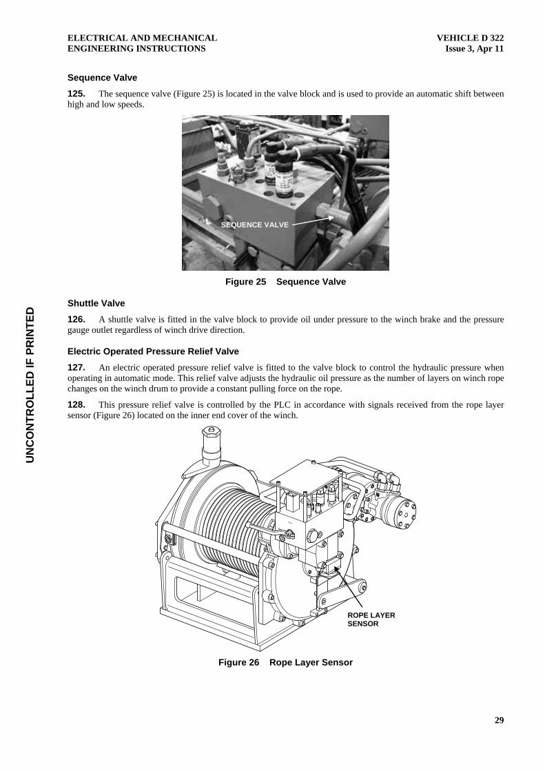
Sequence Valve
125. The sequence valve (Figure 25) is located in the valve block and is used to provide an automatic shift between high and low speeds.
Figure 25 Sequence Valve
Shuttle Valve
126. A shuttle valve is fitted in the valve block to provide oil under pressure to the winch brake and the pressure gauge outlet regardless of winch drive direction.
Electric Operated Pressure Relief Valve
127. An electric operated pressure relief valve is fitted to the valve block to control the hydraulic pressure when operating in automatic mode. This relief valve adjusts the hydraulic oil pressure as the number of layers on winch rope changes on the winch drum to provide a constant pulling force on the rope.
128. This pressure relief valve is controlled by the PLC in accordance with signals received from the rope layer sensor (Figure 26) located on the inner end cover of the winch.
Figure 26 Rope Layer Sensor
SEQUENCE VALVE
ROPE LAYER SENSOR

UN
CO
NTR
OLL
ED IF
PR
INTE
D
VEHICLE D 322 Issue 3, Apr 11
ELECTRICAL AND MECHANICAL ENGINEERING INSTRUCTIONS
30
Pressure Reducing Valve
129. The pressure reducing valve (Figure 27) is a pilot operated valve fitted to the valve block to limit the oil pressure to a maximum of 130 bar. This pressure reducing valve operates whenever the winch is operating in manual mode.
Figure 27 Pressure Reducing Valve, Hydraulic Oil Pressure Measuring Point,
MP3 and MP4 Pressure Sensors
130. When operating in manual mode, the line pull capability for the winch is 13 tonne on the first layer, reducing to 9 tonne on the fourth layer.
Pressure Gauge Outlet
131. A hydraulic oil pressure measuring point (Figure 27) is provided for fitting a pressure gauge to the valve block. This allows for measurement of the hydraulic oil pressure in the brake supply line.
Pressure Transmitters MP3 and MP4
132. Two pressure transmitters are fitted to the valve block at points MP3 and MP4 (Figure 27). The transmitters sense the hydraulic oil pressure at the inlet and discharge sides of the hydraulic motors. MP3 senses the pressure on the inlet side of the motors when winching in, and only when operating in the low-speed, high-torque condition. MP4 senses the discharge pressure from the motors. When winching out, the pressure sensed by these two sensors is reversed.
Winch Drive Motor Assemblies
133. The winch is fitted with three drive motors (Figure 28) that operate in sequence to provide high- or low-speed drive. The motors fitted to the winch are as follows:
a. Danfoss OMH 250. Fitted to the primary drive unit assembly and is coupled to the hydraulic brake. It is used to drive the winch at high-speed, low-torque in light load situations.
b. Danfoss OMH 200. Fitted to the secondary drive unit A and operates in conjunction with the other two motors to drive the winch at low speed, high torque when operating in high load situations.
c. Danfoss OMT 200. Fitted to the secondary drive unit B and operates in conjunction with the other two motors to drive the winch at low speed, high torque when operating in high load situations. This motor also provides the mounting point for the hydraulic valve block.
PILOT OPERATED PRESSURE
REDUCING VALVE
HYDRAULIC OIL PRESSURE
MEASURING POINT
MP4
MP3
UN
CO
NTR
OLL
ED IF
PR
INTE
D
ELECTRICAL AND MECHANICAL ENGINEERING INSTRUCTIONS
VEHICLE D 322 Issue 3, Apr 11
31
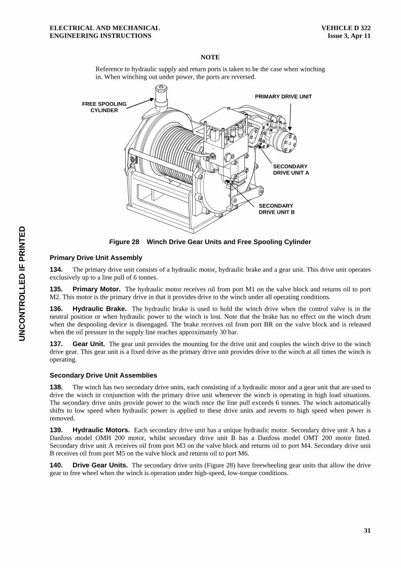
NOTE
Reference to hydraulic supply and return ports is taken to be the case when winching in. When winching out under power, the ports are reversed.
Figure 28 Winch Drive Gear Units and Free Spooling Cylinder
Primary Drive Unit Assembly
134. The primary drive unit consists of a hydraulic motor, hydraulic brake and a gear unit. This drive unit operates exclusively up to a line pull of 6 tonnes.
135. Primary Motor. The hydraulic motor receives oil from port M1 on the valve block and returns oil to port M2. This motor is the primary drive in that it provides drive to the winch under all operating conditions.
136. Hydraulic Brake. The hydraulic brake is used to hold the winch drive when the control valve is in the neutral position or when hydraulic power to the winch is lost. Note that the brake has no effect on the winch drum when the despooling device is disengaged. The brake receives oil from port BR on the valve block and is released when the oil pressure in the supply line reaches approximately 30 bar.
137. Gear Unit. The gear unit provides the mounting for the drive unit and couples the winch drive to the winch drive gear. This gear unit is a fixed drive as the primary drive unit provides drive to the winch at all times the winch is operating.
Secondary Drive Unit Assemblies
138. The winch has two secondary drive units, each consisting of a hydraulic motor and a gear unit that are used to drive the winch in conjunction with the primary drive unit whenever the winch is operating in high load situations. The secondary drive units provide power to the winch once the line pull exceeds 6 tonnes. The winch automatically shifts to low speed when hydraulic power is applied to these drive units and reverts to high speed when power is removed.
139. Hydraulic Motors. Each secondary drive unit has a unique hydraulic motor. Secondary drive unit A has a Danfoss model OMH 200 motor, whilst secondary drive unit B has a Danfoss model OMT 200 motor fitted. Secondary drive unit A receives oil from port M3 on the valve block and returns oil to port M4. Secondary drive unit B receives oil from port M5 on the valve block and returns oil to port M6.
140. Drive Gear Units. The secondary drive units (Figure 28) have freewheeling gear units that allow the drive gear to free wheel when the winch is operation under high-speed, low-torque conditions.
FREE SPOOLING CYLINDER
PRIMARY DRIVE UNIT
SECONDARY DRIVE UNIT B
SECONDARY DRIVE UNIT A

UN
CO
NTR
OLL
ED IF
PR
INTE
D
VEHICLE D 322 Issue 3, Apr 11
ELECTRICAL AND MECHANICAL ENGINEERING INSTRUCTIONS
32
Free Spooling Cylinder
141. A free spooling device is fitted to the frame of each winch above the planetary gear train annulus. This device is a pneumatically operated cylinder and plunger that engages in a drilling in the annulus. When disengaged, the planetary gear train annulus is free to rotate; therefore, allowing the winch drum to rotate freely. When disengaged, the plunger protrudes from the top of the cylinder.
142. The free spooling disengagement cylinders are actuated by an electric/pneumatic solenoid, switched by electrical switches located in each control cabinet (Figure 28).
143. In an emergency situation, the plunger may be disengaged manually by screwing an M8 threaded bolt into the top of the plunger and lifting the plunger up.
Free Spooling Device Control Valve
144. Control valves for the free spooling device are located in the control cabinets on either side of the recovery system.
Drum Brake
145. A drum brake is provided on the winch to provide drag on the planetary gear train annulus. The purpose of this is to prevent uncontrolled despooling of the drum whenever the free spooling device is disengaged.
Torque Control System
146. The torque control system incorporates the following:
a. hydraulic manifold,
b. distance sensor,
c. two pressure transmitters, and
d. PLC.
147. These components combine to measure and regulate the hydraulic pressure applied to the hydraulic motors so that a constant line pull on the winch rope is achieved.
148. The two pressure transmitters, PG1 and PG2, are fitted to the hydraulic manifold to measure the true differential pressure across the motors so that variations in back pressure do not affect the constant line pull. PG1 measures the inlet pressure and PG2 measures the outlet.
149. The hydraulic manifold includes an automatic speed control system for the motors, which shifts between using one motor (high speed, low torque) and three motors (low speed, high torque). The constant force system is only active when all three motors are in use and the pulling force is above 6 tonnes.
150. The winch has two work modes, which are manual and automatic. Work modes are selected by moving the mode selection lever, located on the hydraulic manifold, between the respective two work mode positions. Manual mode position for the lever is indicated by ‘MAN’ stamped into the manifold body. Automatic mode position is indicated by ‘AUTO’ stamped on the manifold. An inductive sensor is also located at the automatic position. The inductive sensor indicates the position of the lever to the PLC. The display panel will show that the winch is operating under automatic control when the lever is in the automatic position. When the lever is in the ‘MAN’ (manual) position, the display will indicate that the winch is operating under manual control.

UN
CO
NTR
OLL
ED IF
PR
INTE
D
ELECTRICAL AND MECHANICAL ENGINEERING INSTRUCTIONS
VEHICLE D 322 Issue 3, Apr 11
33
151. The distance sensor (Figure 29) determines which rope layer is on the winch drum by measuring the distance to the mechanical flag working against the rope from the axis of the drum giving the working radius of the drum.
Figure 29 Distance Sensor
152. The PLC receives signals from the distance sensor and from the two pressure transmitters located in the hydraulic manifold (also referred to as pressure guards), and then provides output signals to the proportional relief valve.
153. The proportional relief valve controls the working pressure for the hydraulic motors according to the signal from the PLC, thereby achieving a constant rope pull regardless of how much rope is spooled up on the winch drum.
154. When operating in automatic mode, the proportional relief valve regulates the hydraulic oil pressure in response to signals received from the PLC in accordance with the layers of steel wire rope on the winch drum.
155. The resultant line pull is a function of the working radius of the winch drum and the hydraulic pressure applied to the motors.
156. When operating in manual mode, the pressure reducing valve limits the hydraulic pressure to 130 bar. The PLC has no control over the winch when operating in manual mode. Manual mode can be used whenever a suspected malfunction of the automatic control system exists.
Cable Tensioning System
157. Winch rope tensioners are fitted to each of the winch rope fairleads. The rope tensioners apply pressure to the winch rope and fairlead sheave to enable the winch rope to be wound onto the winch drums free of any slack.
158. The rope tensioners are operated pneumatically using compressed air from the HRV’s air system. Operation switches are fitted to both the left-hand and right-hand control cabinets.
Steel Wire Rope
159. The Steel Wire Rope (SWR) fitted to this winch has the following specifications:
a. 98.50 m long;
b. 17 mm diameter;
c. 10-part + IWR, right-hand lay;
d. 152.20 mm² steel area;
e. wire tensile strength of 1 960 MPa; and
f. guaranteed minimum breaking strain of 26 000 kg.
MECHANICAL FLAG
DISTANCE SENSOR
UN
CO
NTR
OLL
ED IF
PR
INTE
D
VEHICLE D 322 Issue 3, Apr 11
ELECTRICAL AND MECHANICAL ENGINEERING INSTRUCTIONS
34
PALFINGER CRANE PK 9501
General
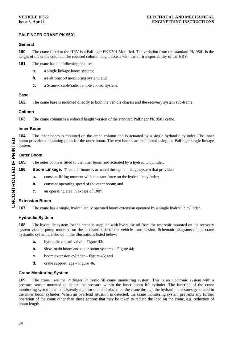
160. The crane fitted to the HRV is a Palfinger PK 9501 Modified. The variation from the standard PK 9501 is the height of the crane column. The reduced column height assists with the air transportability of the HRV.
161. The crane has the following features:
a. a single linkage boom system;
b. a Paltronic 50 monitoring system; and
c. a Scanrec cable/radio remote control system.
Base
162. The crane base is mounted directly to both the vehicle chassis and the recovery system sub-frame.
Column
163. The crane column is a reduced height version of the standard Palfinger PK 9501 crane.
Inner Boom
164. The inner boom is mounted on the crane column and is actuated by a single hydraulic cylinder. The inner boom provides a mounting point for the outer boom. The two booms are connected using the Palfinger single linkage system.
Outer Boom
165. The outer boom is fitted to the inner boom and actuated by a hydraulic cylinder.
166. Boom Linkage. The outer boom is actuated through a linkage system that provides:
a. constant lifting moment with constant force on the hydraulic cylinder;
b. constant operating speed of the outer boom; and
c. an operating area in excess of 180°.
Extension Boom
167. The crane has a single, hydraulically operated boom extension operated by a single hydraulic cylinder.
Hydraulic System
168. The hydraulic system for the crane is supplied with hydraulic oil from the reservoir mounted on the recovery system via the pump mounted on the left-hand side of the vehicle transmission. Schematic diagrams of the crane hydraulic system are shown in the illustrations listed below:
a. hydraulic control valve – Figure 43;
b. slew, main boom and outer boom systems – Figure 44;
c. boom extension cylinder – Figure 45; and
d. crane support legs – Figure 46.
Crane Monitoring System
169. The crane uses the Palfinger Paltronic 50 crane monitoring system. This is an electronic system with a pressure sensor mounted to detect the pressure within the inner boom lift cylinder. The function of the crane monitoring system is to consistently monitor the load placed on the crane through the hydraulic pressures generated in the inner boom cylinder. When an overload situation is detected, the crane monitoring system prevents any further operation of the crane other than those actions that may be taken to reduce the load on the crane, e.g. reduction of boom length.
UN
CO
NTR
OLL
ED IF
PR
INTE
D
ELECTRICAL AND MECHANICAL ENGINEERING INSTRUCTIONS
VEHICLE D 322 Issue 3, Apr 11
35
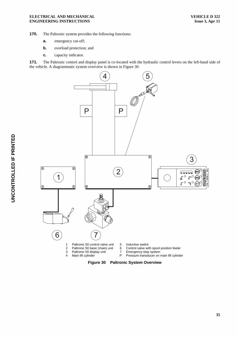
170. The Paltronic system provides the following functions:
a. emergency cut-off;
b. overload protection; and
c. capacity indicator.
171. The Paltronic control and display panel is co-located with the hydraulic control levers on the left-hand side of the vehicle. A diagrammatic system overview is shown in Figure 30.
1 Paltronic 50 control valve unit 5 Inductive switch 2 Paltronic 50 basic (main) unit 6 Control valve with spool position feeler 3 Paltronic 50 display unit 7 Emergency stop system 4 Main lift cylinder P Pressure transducer on main lift cylinder
Figure 30 Paltronic System Overview

UN
CO
NTR
OLL
ED IF
PR
INTE
D
VEHICLE D 322 Issue 3, Apr 11
ELECTRICAL AND MECHANICAL ENGINEERING INSTRUCTIONS
36
172. The layout of the control and display panel is shown in Figure 31.
PALT
RO
NIC
50
60 70 80 90 100
HPLS
ON/OFF
OLP
1 Emergency stop 4 Overload protection system (most not used) 2 Capacity indicator 60-100% (not used) 5 High Power Lifting System (HPLS) (not used) 3 On/Off button (not used) 6 Overload protection system override
Figure 31 Paltronic Control Panel
173. The placement of the Paltronic control system components on the crane is shown in Figure 32.
1 Paltronic 50 control valve unit 3 Inductive switch 2 Paltronic 50 basic (main) unit 4 Control valve with spool position feeler
Figure 32 Paltronic Control System Components
Control Panel
174. Power for the Paltronic system is provided whenever the crane PTO is engaged. Once the system is energised, the Paltronic system switches on automatically; hence, there is no need to switch the system on or off. The Paltronic system may be switched off manually, in which case the display will show Code 98.
175. Main Electronic Control Box. The main electronic control box receives all digital and proportional signals from the crane and controls all outgoing signals.
176. Valve Control. The valve control box monitors the position of the hydraulic control valve spools.
177. Display Unit. The display unit is the interface with the operator, allowing switching of the different functions and to read the actual capacity data.
1
2
3
4
1 2 3
4
5
6

UN
CO
NTR
OLL
ED IF
PR
INTE
D
ELECTRICAL AND MECHANICAL ENGINEERING INSTRUCTIONS
VEHICLE D 322 Issue 3, Apr 11
37
CAN Bus System
178. The electronic components of the Paltronic system are interconnected using a Controller Area Network (CAN) bus system. This system allows the transmission of data in a fast and efficient manner with the minimum of cabling required. The CAN bus system components each have unique addresses; therefore, each of the system components may be connected to any free CAN plug and still operate correctly.
179. The advantage of the CAN bus system is the ability to allow the connection of additional control system units without the need for additional cabling. The inclusion of additional components simply requires the connection of the component to the system and the allocation of an electronic address.
180. CAN Cable. The CAN bus system cable consists of seven wires as shown in Figure 33.
1 CAN bus wire A 5 Power supply ground 2 CAN bus wire B 6 Emergency stop loop 3 CAN bus ground 7 Emergency stop loop 4 Power supply 24 V, if emergency loop is closed 8 Free
Figure 33 CAN Bus Cable
181. Emergency Stops. In the event that any one of the emergency stops are actuated on the crane, the crane cannot be operated until each emergency stop is returned to the unlocked position.
Overload Protection
182. Overload protection indicators (Figure 34) are incorporated into the Paltronic control panel. These indicators are illuminated at the time the overload protection system is actuated and indicate the area of the crane that is in an overload condition. Only the crane overload is used.
183. When the crane is in an overload situation, those functions that will not place the crane in further overload condition or will relieve the overload condition are still allowed; however, the load on the crane may not be increased.
184. If an overload condition exists because of a peak pressure in the main lift cylinder, the peak pressure can be released by pressing the Overload Protection (OLP) button on the Paltronic control panel and lowering the crane. The functions can be operated for 1.50 seconds, after which the crane is locked for 30 seconds if it is still in an overload condition.

UN
CO
NTR
OLL
ED IF
PR
INTE
D
VEHICLE D 322 Issue 3, Apr 11
ELECTRICAL AND MECHANICAL ENGINEERING INSTRUCTIONS
38
PALT
RO
NIC
50
60 70 80 90 100
HPLS
ON/OFF
OLP
1 De-rated area (SHB) (not used) 3 Rope winch (not fitted) 2 Fly jib (not used) 4 Crane
Figure 34 Overload Protection Indicators
185. Codes for Overload. If an overload situation occurs, the codes listed in Table 1 are displayed on the Paltronic main electronic control panel.
Table 1 Paltronic Overload Codes
Code Explanation
03 Overload on crane (normal working area)
07 Not used
30 Not used
32 Not used
90 Not used
93 Load limit on crane overridden by 20 bar
Control Valve
186. The hydraulic control valve controls all hydraulic functions of the crane other than the support legs. The control valve is located on the left-hand side of the vehicle. Each valve spool may be operated by use of the respective control levers fitted to the control valve or by use of the remote control interface (Figure 35).
Figure 35 Hydraulic Control Valve Interface
1 2
3 4
REMOTE CONTROL INTERFACE SOCKET

UN
CO
NTR
OLL
ED IF
PR
INTE
D
ELECTRICAL AND MECHANICAL ENGINEERING INSTRUCTIONS
VEHICLE D 322 Issue 3, Apr 11
39
Support Legs
187. The crane has a support leg on each side of the vehicle. These legs are hydraulically actuated with control levers located on each side of the vehicle. The hydraulic control valve (Figure 36) is located on the left-hand side.
Figure 36 Support Leg Control Valve and Levers
Remote Control System
188. The crane has a combined radio and cable remote control system utilising a common console. A 15 metre cable is provided to connect the remote control console to the crane control system. The cable socket is shown in Figure 35. The crane automatically reverts to cable control whenever the cable is connected.
189. As a radio remote control, the crane operates on any one of 12 frequencies programmed into the crane. The frequencies are selectable from the remote control and are provided to enable the operator to change frequencies in the event of frequency interference. If frequency problems are being experienced, the crane will fail to a safe mode.
190. The remote control console (Figure 37) is battery-powered. A second battery is provided with the crane along with a battery charger, which is mounted in the crew cabin.
Figure 37 Remote Control Console

UN
CO
NTR
OLL
ED IF
PR
INTE
D
VEHICLE D 322 Issue 3, Apr 11
ELECTRICAL AND MECHANICAL ENGINEERING INSTRUCTIONS
40
191. The remote control console has the following control functions:
a. An operating lever for each of the crane functions, other than the stabilisers that must be operated at the main control panel of the crane.
b. Frequency selection button.
c. Micro operation button enabling the operator to adjust the operating speed of the crane to five different settings. The micro switch also allows the operator to place the remote control console into test mode to enable testing of the remote control console functions.
Emergency Manual Operation
192. The crane may be operated in an emergency, manual mode if required, but only to stow the crane and move it to a place for repair (refer to the User Handbook).

UN
CO
NTR
OLL
ED IF
PR
INTE
D
ELECTRICAL AND MECHANICAL ENGINEERING INSTRUCTIONS
VEHICLE D 322 Issue 3, Apr 11
41
Figure 38 HRV Cabin/Chassis Electrical Circuit Diagram

UN
CO
NTR
OLL
ED IF
PR
INTE
D
VEHICLE D 322 Issue 3, Apr 11
ELECTRICAL AND MECHANICAL ENGINEERING INSTRUCTIONS
42
Blank Page

UN
CO
NTR
OLL
ED IF
PR
INTE
D
ELECTRICAL AND MECHANICAL ENGINEERING INSTRUCTIONS
VEHICLE D 322 Issue 3, Apr 11
43
Figure 39 Hydraulic Control Valve Schematic Circuit

UN
CO
NTR
OLL
ED IF
PR
INTE
D
VEHICLE D 322 Issue 3, Apr 11
ELECTRICAL AND MECHANICAL ENGINEERING INSTRUCTIONS
44
Blank Page

UN
CO
NTR
OLL
ED IF
PR
INTE
D
ELECTRICAL AND MECHANICAL ENGINEERING INSTRUCTIONS
VEHICLE D 322 Issue 3, Apr 11
45
Figure 40 Recovery System Main Electrical Circuit

UN
CO
NTR
OLL
ED IF
PR
INTE
D
VEHICLE D 322 Issue 3, Apr 11
ELECTRICAL AND MECHANICAL ENGINEERING INSTRUCTIONS
46
Blank Page

UN
CO
NTR
OLL
ED IF
PR
INTE
D
ELECTRICAL AND MECHANICAL ENGINEERING INSTRUCTIONS
VEHICLE D 322 Issue 3, Apr 11
47
Figure 41 Remote Control Electrical Circuit

UN
CO
NTR
OLL
ED IF
PR
INTE
D
VEHICLE D 322 Issue 3, Apr 11
ELECTRICAL AND MECHANICAL ENGINEERING INSTRUCTIONS
48
Blank Page

UN
CO
NTR
OLL
ED IF
PR
INTE
D
ELECTRICAL AND MECHANICAL ENGINEERING INSTRUCTIONS
VEHICLE D 322 Issue 3, Apr 11
49
Figure 42 Recovery System Pneumatic Circuit (New or Old Diagram?)

UN
CO
NTR
OLL
ED IF
PR
INTE
D
VEHICLE D 322 Issue 3, Apr 11
ELECTRICAL AND MECHANICAL ENGINEERING INSTRUCTIONS
50
Blank Page

UN
CO
NTR
OLL
ED IF
PR
INTE
D
ELECTRICAL AND MECHANICAL ENGINEERING INSTRUCTIONS
VEHICLE D 322 Issue 3, Apr 11
51
Figure 43 Hydraulic Control Valve Circuit

UN
CO
NTR
OLL
ED IF
PR
INTE
D
VEHICLE D 322 Issue 3, Apr 11
ELECTRICAL AND MECHANICAL ENGINEERING INSTRUCTIONS
52
Blank Page

UN
CO
NTR
OLL
ED IF
PR
INTE
D
ELECTRICAL AND MECHANICAL ENGINEERING INSTRUCTIONS
VEHICLE D 322 Issue 3, Apr 11
53
Figure 44 Slew, Main Boom and Outer Boom Systems

UN
CO
NTR
OLL
ED IF
PR
INTE
D
VEHICLE D 322 Issue 3, Apr 11
ELECTRICAL AND MECHANICAL ENGINEERING INSTRUCTIONS
54
Blank Page

UN
CO
NTR
OLL
ED IF
PR
INTE
D
ELECTRICAL AND MECHANICAL ENGINEERING INSTRUCTIONS
VEHICLE D 322 Issue 3, Apr 11
55
Figure 45 Boom Extension Cylinder

UN
CO
NTR
OLL
ED IF
PR
INTE
D
VEHICLE D 322 Issue 3, Apr 11
ELECTRICAL AND MECHANICAL ENGINEERING INSTRUCTIONS
56
Blank Page

UN
CO
NTR
OLL
ED IF
PR
INTE
D
ELECTRICAL AND MECHANICAL ENGINEERING INSTRUCTIONS
VEHICLE D 322 Issue 3, Apr 11
57
Figure 46 Crane Support Legs
END Distribution List: VEH D 30.0 – Code 4 (Maint Level)
(Sponsor: CGSVSPO Mdm/Hvy B Vehicles) (Authority: CGSVSPO ECO 11/11)


