Embed Size (px)
Citation preview
UN
CO
NTR
OLL
ED IF
PR
INTE
D
ELECTRICAL AND MECHANICAL ENGINEERING INSTRUCTIONS
VEHICLE G 832-2 Issue 2, Feb 10
1
TRUCK, MC4, MACK, CH FLEETLINER
CARGO W/CRANE
TECHNICAL DESCRIPTION
This instruction is authorised for use by command of the Chief of Army. It provides direction, mandatory controls and procedures for the operation, maintenance and support of equipment. Personnel are to carry out any action required by this instruction in accordance with EMEI General A 001.
TABLE OF CONTENTS
Page No Page No Introduction ................................................................................3 Associated Publications .............................................................3 Arrangement of the Equipment ..................................................3 Detailed Technical Description...................................................3
Crane .....................................................................................3 Base ..................................................................................4 Crane Column ...................................................................7 Inner Boom........................................................................7 Outer boom .......................................................................8 Extendable Booms ............................................................8 Crane Controls ..................................................................9
Hydraulic System.................................................................11 Power Take-off (PTO) .....................................................12 Hydraulic Pump...............................................................12 Hydraulic Tank ................................................................13 High Pressure Filter ........................................................13
Control Valve Bank ......................................................... 13 Overload Block ............................................................... 13 Pressure Sensing Switch................................................ 13 Load Holding Valves....................................................... 13 Double Acting Load Holding Valve ................................. 13
Hydraulic Circuits ................................................................ 13 Stabiliser Legs ................................................................ 14 Slew ................................................................................ 14 Boom .............................................................................. 14 Outer Boom .................................................................... 14 Extendable Arms ............................................................ 14
Safety Systems ................................................................... 14 Emergency Cut-off Switch .............................................. 14 Load Moment Limit System (Overload Protection) ......... 15
Crane Electrical System ...................................................... 18
LIST OF FIGURES
Page No Page No Figure 1 Truck, MC4, Mack, CH Fleetliner, Cargo
W/Crane ........................................................................3 Figure 2 Major Crane Components.........................................4 Figure 3 Crane Base ...............................................................5 Figure 4 Outrigger Extension Arms.........................................5 Figure 5 Stabiliser Leg ............................................................6 Figure 6 Slew Cylinder and Piston Rack.................................6 Figure 7 Crane Column...........................................................7 Figure 8 Inner Boom ...............................................................7 Figure 9 Outer Boom...............................................................8 Figure 10 First Extendable Boom............................................8 Figure 11 Second Extendable Boom ......................................9 Figure 12 Main Console ..........................................................9
Figure 13 Auxiliary Console.................................................. 10 Figure 14 Crane Function Decals ......................................... 11 Figure 15 PTO ...................................................................... 12 Figure 16 PTO and Pump..................................................... 12 Figure 17 Hydraulic Tank...................................................... 13 Figure 18 Emergency Cut-Off Circuit.................................... 15 Figure 19 Safety Console ..................................................... 15 Figure 20 Electro-Hydraulic Overload Protection Circuit ...... 16 Figure 21 Load Holding Valve and Pressure Switch ............ 16 Figure 22 Proximity Switch ................................................... 17 Figure 23 Overload Circuits .................................................. 17 Figure 24 Crane Hydraulic Circuit......................................... 19
UN
CO
NTR
OLL
ED IF
PR
INTE
D
VEHICLE G 832-2 Issue 2, Feb 10
ELECTRICAL AND MECHANICAL ENGINEERING INSTRUCTIONS
2
Blank Page

UN
CO
NTR
OLL
ED IF
PR
INTE
D
ELECTRICAL AND MECHANICAL ENGINEERING INSTRUCTIONS
VEHICLE G 832-2 Issue 2, Feb 10
3
INTRODUCTION
1. This EMEI contains the technical description of the crane fitted to the Truck, MC4, Mack, CH Fleetliner, Cargo W/Crane, as illustrated at Figure 1.
Figure 1 Truck, MC4, Mack, CH Fleetliner, Cargo W/Crane
ASSOCIATED PUBLICATIONS
2. For technical data and other relevant information pertaining to the base truck, reference may be necessary to the latest issue of the following documents:
a. Australian Army Books – Record book for Service Equipment GM 120;
b. Defence Road Transport Instructions (DRTI);
c. EMEI Vehicle G 830-1 – Data Summary;
d. EMEI Vehicle G 830-2 – Data Summary; and
e. EMEI Vehicle G 832-1 – Technical Description.
ARRANGEMENT OF THE EQUIPMENT
3. The Truck, MC4, Mack, CH Fleetliner, Cargo W/Crane is a Mack CH 788 RS Fleetliner cab chassis which has been fitted with a cargo tray and hydraulic crane to facilitate self loading/unloading and the transfer of loads between vehicles.
DETAILED TECHNICAL DESCRIPTION
CRANE
4. The crane unit is a Palfinger PK 9501 A. Its lifting capacity varies from 4 990 kg at 1.6 m outreach to 1 110 kg at 7.6 m outreach (Figure 2).

UN
CO
NTR
OLL
ED IF
PR
INTE
D
VEHICLE G 832-2 Issue 2, Feb 10
ELECTRICAL AND MECHANICAL ENGINEERING INSTRUCTIONS
4
1 Crane column 8 Extendable booms 14 Controls 2 Hydraulic elevating cylinder 9 Control valve 15 Stabiliser cylinder 3 Inner boom 9A Control unit – control valve side 16 Outrigger 4 Outer boom cylinder 10 Shackle bolts 17 5° spirit level 5 Hinge pin 11 Rocker 18 Hydraulic tank 6 Outer boom 12 Slewing mechanism 19 Hydraulic fluid level indicator 7 Hydraulic cylinders (extendable
booms) 13 Control unit (Right-hand side) 20 Hook
Figure 2 Major Crane Components
5. The crane comprises the following sub-assemblies:
a. base,
b. crane column,
c. inner boom,
d. outer boom,
e. extendable booms, and
f. controls.
Base
6. The crane’s base (Figure 3) is a prefabricated steel structure which provides a stable operating platform for crane operation and houses the slew mechanism and outriggers. Mounting points for the hydraulic tank, control valves and control consoles are also located on the base.

UN
CO
NTR
OLL
ED IF
PR
INTE
D
ELECTRICAL AND MECHANICAL ENGINEERING INSTRUCTIONS
VEHICLE G 832-2 Issue 2, Feb 10
5
Figure 3 Crane Base
7. Outriggers. The outriggers or stabilising extensions (Figure 4) are housed in the crane base and are manually extended or retracted. A spring-loaded pin locks the arms in either position.
Figure 4 Outrigger Extension Arms
8. Stabilising Legs. The stabilising legs are fitted to the outriggers and pivot to allow them to be stowed in the inverted position for transport. The legs are locked into the required position by a spring-loaded pin. The stabiliser legs themselves (Figure 5) are double acting hydraulic cylinders with a base plate mounted on the outer end of the piston rod.
9. Paras 39 to 41 detail the operation of the hydraulic circuit.

UN
CO
NTR
OLL
ED IF
PR
INTE
D
VEHICLE G 832-2 Issue 2, Feb 10
ELECTRICAL AND MECHANICAL ENGINEERING INSTRUCTIONS
6
Figure 5 Stabiliser Leg
10. Slew System. The slew system of the crane (Figure 6) is of rack and pinion type, which uses two opposing single acting cylinders with a common piston/rack. The rack is engaged with the pinion gear that is fixed to the base of the crane column. When oil flow is directed into the end of a slew cylinder, the piston/rack is forced towards the opposite cylinder, thus turning the pinion gear and consequently the crane column. The slew gearbox allows the crane to operate through an arc of approximately 400°.
11. Para 42 details the operation of the slew system’s hydraulic circuit.
Figure 6 Slew Cylinder and Piston Rack

UN
CO
NTR
OLL
ED IF
PR
INTE
D
ELECTRICAL AND MECHANICAL ENGINEERING INSTRUCTIONS
VEHICLE G 832-2 Issue 2, Feb 10
7
Crane Column
12. The crane column (Figure 7) mounts into the crane base supported by two bearings and secured by a circlip at the base of the column. A pinion gear forms part of the lower column, and is in constant mesh with the slew piston/rack. The top of crane column is fitted with bushed mounting points for the boom and gussets for the piston end of the boom cylinder.
Figure 7 Crane Column
Inner Boom
13. The inner boom (Figure 8) has provisions for three main attachments as follows:
a. a mounting point incorporating a pivot pin and bushes for attachment to the crane column,
b. gussets for attachment of the cylinder ends of both the boom cylinder and the outer boom cylinder, and
c. a mounting point incorporating bushes for mounting of the outer boom.
Figure 8 Inner Boom
14. Hydraulic Elevating Cylinder. The function of the hydraulic elevating cylinder (Figure 7) is to raise and lower the inner boom during crane operation. It is mounted to the upper section of the crane column and the piston rod end is mounted to the underside of the inner boom. A load holding valve (Para 36) and pressure sensing switch (Para 35) are mounted to the cylinder.
UN
CO
NTR
OLL
ED IF
PR
INTE
D
VEHICLE G 832-2 Issue 2, Feb 10
ELECTRICAL AND MECHANICAL ENGINEERING INSTRUCTIONS
8
15. Paras 43 to 44 detail the operation of the hydraulic circuit.
Outer boom
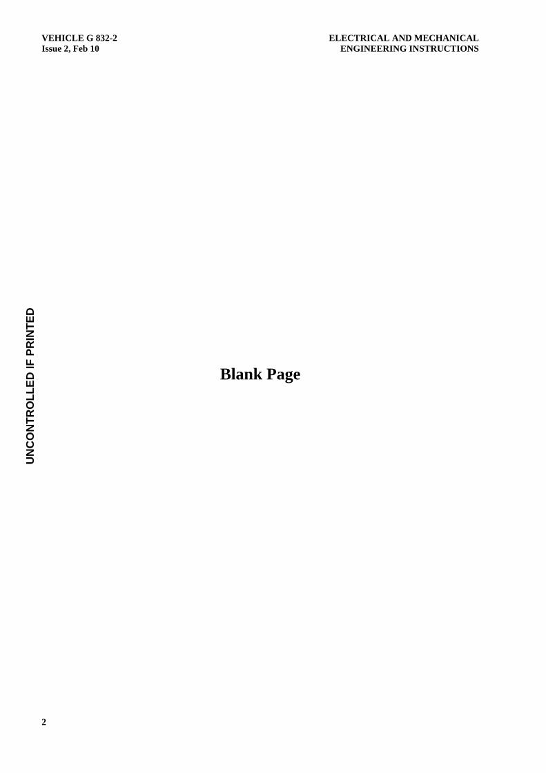
16. The outer boom (Figure 9) features mounting points for attachment to the boom and piston end of the outer boom cylinder. It also features attachment points for the extendable arms’ cylinders and houses the extendable arms within its length.
Figure 9 Outer Boom
17. Outer Boom Cylinder. The function of the outer boom cylinder is to raise and lower the outer boom during crane operation. It is mounted to the underside of the inner boom and the piston rod end is mounted to the linkages on the underside of the outer boom. A load holding valve (Para 36) is mounted to the cylinder to protect the load from lowering when the hydraulic system is inactive.
18. Paras 45 to 46 detail the operation of the hydraulic circuit.
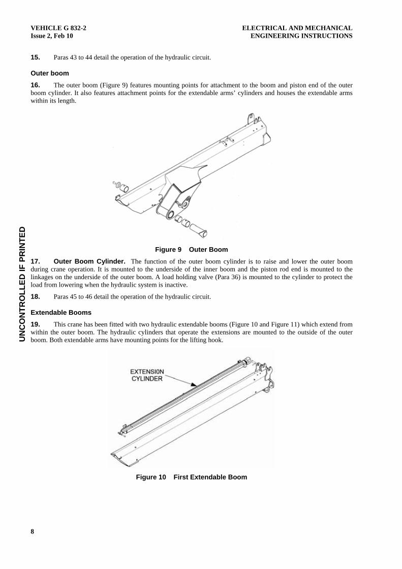
Extendable Booms
19. This crane has been fitted with two hydraulic extendable booms (Figure 10 and Figure 11) which extend from within the outer boom. The hydraulic cylinders that operate the extensions are mounted to the outside of the outer boom. Both extendable arms have mounting points for the lifting hook.
Figure 10 First Extendable Boom

UN
CO
NTR
OLL
ED IF
PR
INTE
D
ELECTRICAL AND MECHANICAL ENGINEERING INSTRUCTIONS
VEHICLE G 832-2 Issue 2, Feb 10
9
Figure 11 Second Extendable Boom
20. Extendable Boom Cylinders. The function of the extendable boom cylinders is to extend and retract the extendable booms during crane operation. The first cylinder is mounted to the outside of the boom end of the outer boom with the piston rod end attached to a mounting bracket on the outer end of the first extendable boom. The second cylinder has a bracket mounted to its piston end which locates in the slide channel attached to the first cylinder. The piston rod end is attached to a mounting bracket on the outer end of the second extendable boom. As the booms are extended, the second cylinder slides along the channel on the first cylinder and extends the second boom simultaneously.
21. A double acting load holding valve has been fitted into the extendable boom circuit to speed up the operation of the extendable boom cylinders.
22. Paras 47 to 49 detail the operation of the hydraulic circuit.
Crane Controls
23. Control Unit. The main control unit (Figure 12) is mounted over the spool valve on the left-hand side of the crane between the outrigger housing and the cab. The lower section of the console has slots for the control levers while the upper section houses the emergency stop switch, manual override button and crane operation indicator (LED display). A levelling bubble is mounted at the right-hand side of the console.
Figure 12 Main Console

UN
CO
NTR
OLL
ED IF
PR
INTE
D
VEHICLE G 832-2 Issue 2, Feb 10
ELECTRICAL AND MECHANICAL ENGINEERING INSTRUCTIONS
10
24. Auxiliary Console. An auxiliary console (Figure 13) is located on the opposite side of the crane with the control levers being connected to the spool valve via transverse rods. The auxiliary console does not include crane operation indicator LEDs.
Figure 13 Auxiliary Console
25. Control Valve. The control valve mounted under the control unit on the left-hand side of the vehicle controls the operation of the following :
a. stabiliser legs,
b. slew mechanism,
c. inner boom,
d. outer boom, and
e. extendable booms.
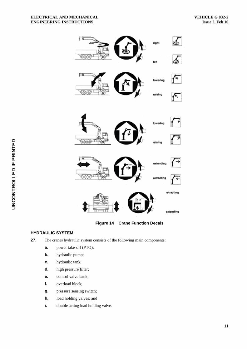
26. The function of each lever is indicated by decals affixed to the control console as shown in Figure 14.
UN
CO
NTR
OLL
ED IF
PR
INTE
D
ELECTRICAL AND MECHANICAL ENGINEERING INSTRUCTIONS
VEHICLE G 832-2 Issue 2, Feb 10
11
Figure 14 Crane Function Decals
HYDRAULIC SYSTEM
27. The cranes hydraulic system consists of the following main components:
a. power take-off (PTO);
b. hydraulic pump;
c. hydraulic tank;
d. high pressure filter;
e. control valve bank;
f. overload block;
g. pressure sensing switch;
h. load holding valves; and
i. double acting load holding valve.
UN
CO
NTR
OLL
ED IF
PR
INTE
D
VEHICLE G 832-2 Issue 2, Feb 10
ELECTRICAL AND MECHANICAL ENGINEERING INSTRUCTIONS
12
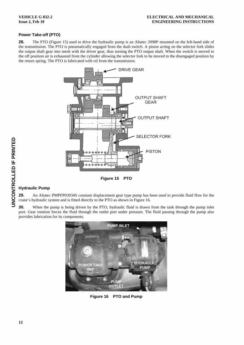
Power Take-off (PTO)
28. The PTO (Figure 15) used to drive the hydraulic pump is an Altatec 2098P mounted on the left-hand side of the transmission. The PTO is pneumatically engaged from the dash switch. A piston acting on the selector fork slides the output shaft gear into mesh with the driver gear, thus turning the PTO output shaft. When the switch is moved to the off position air is exhausted from the cylinder allowing the selector fork to be moved to the disengaged position by the return spring. The PTO is lubricated with oil from the transmission.
Figure 15 PTO
Hydraulic Pump
29. An Altatec PMPFP03034S constant displacement gear type pump has been used to provide fluid flow for the crane’s hydraulic system and is fitted directly to the PTO as shown in Figure 16.
30. When the pump is being driven by the PTO, hydraulic fluid is drawn from the tank through the pump inlet port. Gear rotation forces the fluid through the outlet port under pressure. The fluid passing through the pump also provides lubrication for its components.
Figure 16 PTO and Pump
UN
CO
NTR
OLL
ED IF
PR
INTE
D
ELECTRICAL AND MECHANICAL ENGINEERING INSTRUCTIONS
VEHICLE G 832-2 Issue 2, Feb 10
13
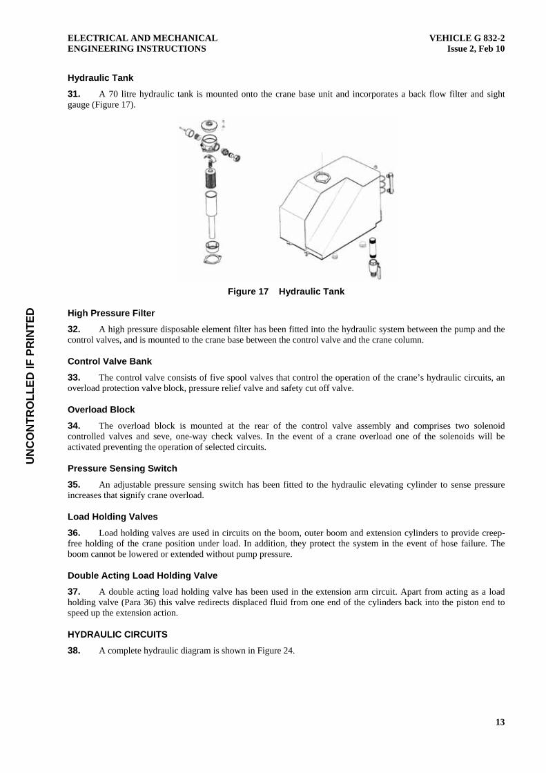
Hydraulic Tank
31. A 70 litre hydraulic tank is mounted onto the crane base unit and incorporates a back flow filter and sight gauge (Figure 17).
Figure 17 Hydraulic Tank
High Pressure Filter
32. A high pressure disposable element filter has been fitted into the hydraulic system between the pump and the control valves, and is mounted to the crane base between the control valve and the crane column.
Control Valve Bank
33. The control valve consists of five spool valves that control the operation of the crane’s hydraulic circuits, an overload protection valve block, pressure relief valve and safety cut off valve.
Overload Block
34. The overload block is mounted at the rear of the control valve assembly and comprises two solenoid controlled valves and seve, one-way check valves. In the event of a crane overload one of the solenoids will be activated preventing the operation of selected circuits.
Pressure Sensing Switch
35. An adjustable pressure sensing switch has been fitted to the hydraulic elevating cylinder to sense pressure increases that signify crane overload.
Load Holding Valves
36. Load holding valves are used in circuits on the boom, outer boom and extension cylinders to provide creep-free holding of the crane position under load. In addition, they protect the system in the event of hose failure. The boom cannot be lowered or extended without pump pressure.
Double Acting Load Holding Valve
37. A double acting load holding valve has been used in the extension arm circuit. Apart from acting as a load holding valve (Para 36) this valve redirects displaced fluid from one end of the cylinders back into the piston end to speed up the extension action.
HYDRAULIC CIRCUITS
38. A complete hydraulic diagram is shown in Figure 24.

UN
CO
NTR
OLL
ED IF
PR
INTE
D
VEHICLE G 832-2 Issue 2, Feb 10
ELECTRICAL AND MECHANICAL ENGINEERING INSTRUCTIONS
14
Stabiliser Legs
39. A single spool valve is used to control both stabiliser legs. When the control lever is moved downwards oil flow is directed into the piston end of the cylinders through the lockout and one-way pilot controlled check valves to extend the legs. Displaced oil from the rod end of the cylinders returns to the tank through the spool valve.
40. To retract the legs, the control lever is raised directing oil flow to the rod end of the cylinder. Pilot pressure from the oil flowing to the rod end also opens the one-way check valve at the piston end allowing oil to flow back to the tank as the leg retracts.
41. To adjust legs separately the lockout valve of the leg to be moved must be in the unlocked position while the opposite valve must be in the locked position. Oil flow will then only be permitted to the unlocked leg.
Slew
42. The slew circuit uses a single open centred, three-position, self-centring spool valve to control the rotation of the crane. When the control lever is moved down, oil flow is directed to the right-hand end of the slew cylinder through the one-way check valve exerting force onto the piston and pushing it towards the opposite end of the cylinder. This movement of the piston/rack assembly turns the crane column in an anticlockwise direction. Displaced oil from the opposite end of the cylinder returns through the one way restrictor, to the spool valve and back to the tank.
Boom
43. The boom circuit comprises a spool valve, load holding valve, pre-tension valve, pressure switch and hydraulic cylinder.
44. When the control lever is moved downwards, pressurised oil is directed to the boom cylinder’s load holding valve. The check valve is lifted off its seat allowing oil to flow through the relief valve and on to the piston side of the boom cylinder. The oil pressure exerted on the piston will push it up the cylinder thus raising the boom. Displaced oil from the rod side of the piston returns through the pre-tension valve, then via the spool valve to the return channel. The pressure switch senses excess pressure (overload) in the boom circuit energising one of the solenoids on the overload protection block as determined by the position of the outer boom.
Outer Boom
45. The outer boom circuit comprises a spool valve, load holding valve and hydraulic cylinder.
46. When the control lever is moved downwards, pressurised oil is directed to the boom cylinder’s load holding valve. The check valve is lifted off its seat allowing oil to flow through the relief valve and on to the piston side of the outer boom cylinder. The oil pressure exerted on the piston will push it up the cylinder thus raising the outer boom. Displaced oil from the rod side of the piston returns through the spool valve to the return channel.
Extendable Arms
47. The circuit used to control the extendable arms consists of a spool valve, double acting load holding valve and two hydraulic cylinders.
48. When the control lever is moved upwards, oil flow is directed through the double acting load holding valve to the piston end of the first extension cylinder. As the piston moves up the cylinder extending the first extendable arm, displaced oil from the rod side of the cylinder passes to the piston end of the second extension cylinder, moving it up its cylinder and extending the second extendable arm. The displaced oil from the second cylinder returns to the double acting load holding valve where it is directed back to the piston side of the first extension cylinder. This action is referred to as ‘return oil utilisation’ and speeds up the extension process. The double acting load holding valve keeps both ends of the cylinder under pressure to control the movement of the arms.
49. To retract the extendable arms, the control lever is moved downwards and the spool valve directs oil flow to the rod end of the cylinders. Pilot pressure from the rod side opens the relief valve in the piston side of the load holding valve, allowing return oil to pass back through the spool valve and to the tank.
SAFETY SYSTEMS
Emergency Cut-off Switch
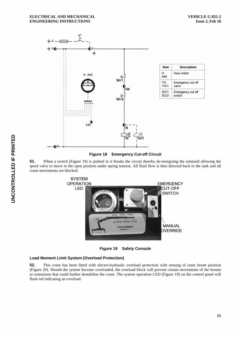
50. The emergency cut-off circuit (Figure 18) comprises two locking push button cut off switches, one at each control panel, and a solenoid controlled emergency cut off valve.
UN
CO
NTR
OLL
ED IF
PR
INTE
D
ELECTRICAL AND MECHANICAL ENGINEERING INSTRUCTIONS
VEHICLE G 832-2 Issue 2, Feb 10
15
Figure 18 Emergency Cut-off Circuit
51. When a switch (Figure 19) is pushed in it breaks the circuit thereby de-energising the solenoid allowing the spool valve to move to the open position under spring tension. All fluid flow is then directed back to the tank and all crane movements are blocked.
Figure 19 Safety Console
Load Moment Limit System (Overload Protection)
52. This crane has been fitted with electro-hydraulic overload protection with sensing of outer boom position (Figure 20). Should the system become overloaded, the overload block will prevent certain movements of the booms or extensions that could further destabilise the crane. The system operation LED (Figure 19) on the control panel will flash red indicating an overload.
UN
CO
NTR
OLL
ED IF
PR
INTE
D
VEHICLE G 832-2 Issue 2, Feb 10
ELECTRICAL AND MECHANICAL ENGINEERING INSTRUCTIONS
16
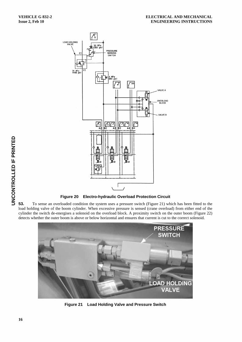
Figure 20 Electro-hydraulic Overload Protection Circuit
53. To sense an overloaded condition the system uses a pressure switch (Figure 21) which has been fitted to the load holding valve of the boom cylinder. When excessive pressure is sensed (crane overload) from either end of the cylinder the switch de-energises a solenoid on the overload block. A proximity switch on the outer boom (Figure 22) detects whether the outer boom is above or below horizontal and ensures that current is cut to the correct solenoid.
Figure 21 Load Holding Valve and Pressure Switch
UN
CO
NTR
OLL
ED IF
PR
INTE
D
ELECTRICAL AND MECHANICAL ENGINEERING INSTRUCTIONS
VEHICLE G 832-2 Issue 2, Feb 10
17
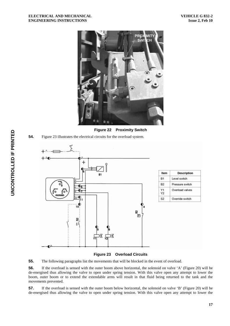
Figure 22 Proximity Switch
54. Figure 23 illustrates the electrical circuits for the overload system.
Figure 23 Overload Circuits
55. The following paragraphs list the movements that will be blocked in the event of overload.
56. If the overload is sensed with the outer boom above horizontal, the solenoid on valve ‘A’ (Figure 20) will be de-energised thus allowing the valve to open under spring tension. With this valve open any attempt to lower the boom, outer boom or to extend the extendable arms will result in that fluid being returned to the tank and the movements prevented.
57. If the overload is sensed with the outer boom below horizontal, the solenoid on valve ‘B’ (Figure 20) will be de-energised thus allowing the valve to open under spring tension. With this valve open any attempt to lower the

UN
CO
NTR
OLL
ED IF
PR
INTE
D
VEHICLE G 832-2 Issue 2, Feb 10
ELECTRICAL AND MECHANICAL ENGINEERING INSTRUCTIONS
18
boom, raise the outer boom or extend the extendable arms will result in that fluid being returned to the tank and the movements prevented.
CRANE ELECTRICAL SYSTEM
58. The crane uses 12 V dc power from the vehicle’s electrical system to energise the solenoids used to operate the emergency shut-off and overload protection systems. Figure 18, Figure 20 and Figure 23 show the electrical circuits.

UN
CO
NTR
OLL
ED IF
PR
INTE
D
ELECTRICAL AND MECHANICAL ENGINEERING INSTRUCTIONS
VEHICLE G 832-2 Issue 2, Feb 10
19
Figure 24 Crane Hydraulic Circuit
END Distribution List: VEH G 60.0 – Code 2 (Maint Level)
(Sponsor: CGSVSPO Mdm/Hvy B Vehicles) (Authority ECO LVSPO 069/09)