Embed Size (px)
Citation preview

TRUCK MOUNTEDHYDRAULIC CRANE
• • • • • • • • • • • • • • • • • • • • •
2 GROVE TMS500E
Thispage is7-5/8”
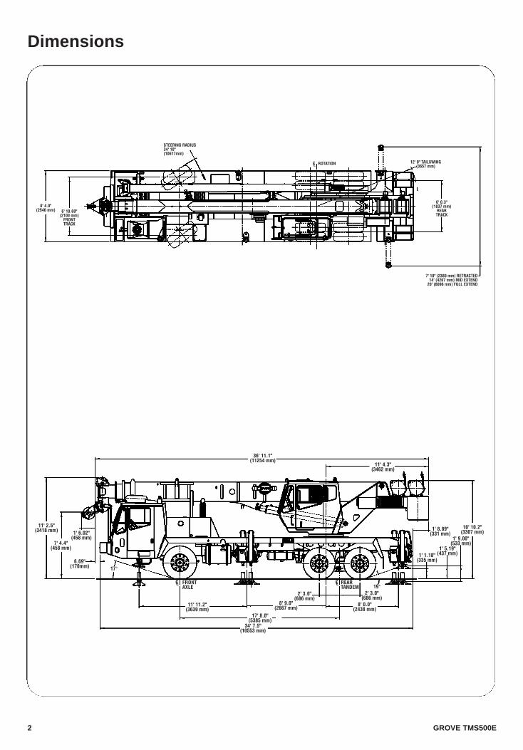
11' 2.5"(3418 mm)
7' 4.4"(458 mm)
1' 6.02"(458 mm)
6.69"(170mm)
36' 11.1"(11254 mm)
11' 4.3"(3462 mm)
1' 8.89"(331 mm)
1' 9.00"(533 mm)
1' 5.19"(437 mm)1' 1.18"
(335 mm)
19°2' 3.0"
(686 mm)8' 0.0"
(2438 mm)
2' 3.0"(686 mm)
8' 9.0"(2667 mm)
17' 8.0"(5385 mm)
34' 7.5"(10553 mm)
11' 11.2"(3639 mm)
10' 10.2"(3307 mm)
CL REARTANDEM
CL FRONTAXLE
17°
8' 4.0"(2540 mm) 6' 10.69"
(2100 mm)FRONTTRACK
STEERING RADIUS34' 10"(10617mm)
CL ROTATION 12' 0" TAILSWING(3657 mm)
6' 0.3"(1837 mm)
REARTRACK
7' 10" (2380 mm) RETRACTED14' (4267 mm) MID EXTEND
20' (6096 mm) FULL EXTEND
Dimensions

3 GROVE TMS500E
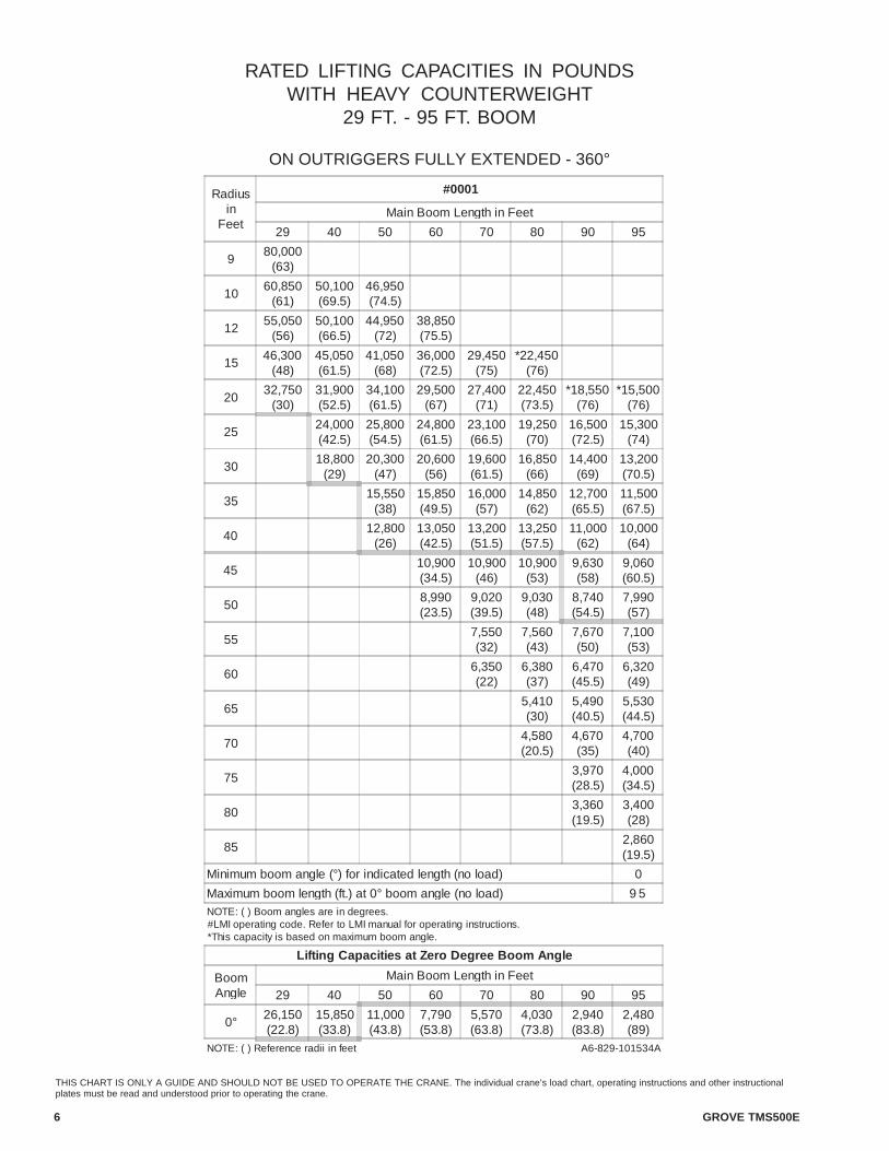
THIS CHART IS ONLY A GUIDE AND SHOULD NOT BE USED TO OPERATE THE CRANE. The individual crane’s load chart, operating instructions and otherinstructional plates must be read and understood prior to operating the crane.
Working Range DiagramThispage is7-5/8”
HE
IGH
T FR
OM
GR
OU
ND
IN F
EE
T
BO
OM
LE
NG
TH A
ND
EX
TEN
SIO
N IN
FE
ET
OPERATING RADIUS IN FEET FROM AXIS OF ROTATION
(BOOM DEFLECTION NOT SHOWN)
45' EXT.
26' EXT.
9590
80
70
60
50
40
29
76°MAXBOOMANGLE
AXIS OFROTATION
140 120 100 80 60 40 20130 110 90 70 50 30 10
160
150
140
130
120
110
100
90
80
70
60
50
40
30
20
10
0
70°
30°OFFSET0°OFFSET
0°
10°
20°
30°
40°
50°
60°
DIMENSIONS ARE FORLARGEST GROVE FURNISHEDHOOK BLOCK AND HEADACHEBALL, WITH ANTI-TWOBLOCK ACTIVATED.
8' - 2" 7' - 8"
29-95 ft. 26-45 ft. 8,790 lbs. 100% 360°(8.8-29 m) (7.9-13.7m) (3 987 kg)
4 GROVE TMS500E
Superstructure Specifications
Boom29 ft. - 95 ft. (8.8 m - 29 m) four-section, full power boom.Maximum tip height: 102.5 ft. (31.2 m)
Telescopic Swingaway Extension26 ft. - 45 ft. (7.92 m - 13.7 m) telescoping offsettableswingaway extension. Offsettable at 0° and 30°. Stowsalongside base boom section. Maximum tip height: 146 ft.(44.5 m)
Boom NoseFour nylatron sheaves mounted on heavy duty taperedroller bearings with removable pin-type rope guards. Quickreeve type boom nose. *Optional removable/stowableauxiliary boom nose with removable pin type rope guard.
Boom ElevationOne double-acting hydraulic cylinder with integral holdingvalve provides elevation from -3° to +76°.
Load Moment & Anti-Two Block SystemStandard “Graphic Display” load moment and anti-twoblock system with audio-visual warning and control leverlockout. These systems provide electronic display ofboom angle, length, radius, tip height, counterweight,relative load moment, maximum permissible load, loadindication and warning of impending two-block condition.The standard Work Area Definition System allows theoperator to pre-select and define safe working areas. If thecrane approaches the pre-set limits, audio-visualwarnings aid the operator in avoiding job-siteobstructions.
CabFull vision, all steel fabricated with acoustical lining andtinted safety glass throughout. Deluxe seat incorporatesarmrest mounted hydraulic single-axis controllers. Dashpanel incorporates gauges for all engine functions. Otherstandard features include: hot water heater, cabcirculating air fan, sliding side and rear windows, sliding
SwingPlanetary swing with foot applied multi-disc brake. Springapplied, hydraulically released swing brake and plunger-type, one position, mechanical house lock operated fromcab. 360° mechanical swing lock. Maximum speed: 3.0RPM
CounterweightStandard 2,630 lbs. (1 193 kg), consisting of 330 lbs. (150kg) on front bumper and 2300 lbs. (1 043kg) onsuperstructure. Optional: 8,790 lbs. (3 987 kg) heavycounterweight package.
Hydraulic SystemTwo main gear pumps with a combined capacity off 127.7GPM (483 L/min). Maximum operating pressure: 3500 PSI(26.2 MPa). Two individual valve banks. Return line typefilter with full flow by-pass protection and service indicator.Replaceable cartridge with micron filtration rating of2/20/75. 96 gallon (363 L) reservoir. Oil cooler on carrier.System pressure test ports.
HOIST SPECIFICATIONSMain and Auxiliary HoistModel HP15B-17GPlanetary reduction with automatic spring applied multi-disc brake. Grooved drum. Electronic hoist drum rotationindicator and hoist drum cable followers.Maximum Single Line Speed: 429 FPM (136 m/min)Maximum Permissible Line Pull:w/standard 6 x 37 class rope: 11,190 lbs. (5076 kg)w/optional 18 x 19 class rope: 9,080 lbs. (4119 kg)Rope Diameter: 5/8 in. (16 mm)Rope Length: 450 ft. (137 m)Rope Type: 6 x 37 class EIPS IWRC*Optional 18 x 19 class rotation resistantMaximum Rope Stowage: 750 ft. (228 m)
*Denotes optional equipment
skylight with electric wiper, electric windshield wash/wipe,fire extinguisher, 12v power outlet, and seat belt.
GROVE TMS500E 5
Carrier Specifications
ChassisBox section frame fabricated from high-strength, alloysteel. Integral outrigger housings and front/rear towingand tie down lugs.
Outrigger SystemHydraulic single-stage, double box beam outriggers withfront stabilizer and inverted jack design; equipped withintegral holding valves. Three positions with fullyextended, intermediate (50%) extended and fullyretracted settings. Steel fabricated, outrigger pads, 24 in.(610 mm) round. A permanently stowed, front centerstabilizer pad, aluminum. Optional aluminum outriggerpads available in place of steel. Maximum outriggerpad load: 72,000 lbs. (32 659 kg)
Outrigger ControlsLocated in the superstructure cab on the left side(umbilical design), requires two hand operation. Cranelevel indicator (sight bubble) on right side console. Carriermounted controls located on each side of the carrier forinitial setup.
EngineCaterpillar 3126B HUEI, six cylinder, turbochargedand after cooled diesel, 442 cu. in. (7.25 L) 300 bhp(224 kW) (gross) @ 2,200 RPM.Maximum torque: 860 ft. lbs. (1166 Nm) @ 1,400 RPM
Fuel Tank Capacity60 gallons (227 L)
Electrical SystemTwo 12 V low maintenance batteries. 12 V system with12 V headlights. Battery disconnect in battery boxcompartment.
Drive6 x 4 x 2
SteeringFront axles, mechanical with hydraulic power assistcontrolled by steering wheel.
TransmissionAllison automatic 6 speeds forward and 1 reverse.
AxlesFront: (1) Rockwell, beam type steering axle, 82.7 in.(2.10 m) track. Capacity: 21,000 lbs. (9526 kg)Rear: (2) Rockwell single reduction drive, 72.3 in.(1.84 m) track. Inter-axle differential lock.Capacity: 41,000 lbs. (18 598 kg)
BrakesS-cam, dual line air system operating on all wheels.Spring-applied, air released parking brake acting on rearaxles. Air dryer standard.
TiresStandard Front: 425/65R22.5 radial highway treadtubeless singles.Standard Rear: 11R22.5 highway tread tube type duals.
SuspensionFront: Spring mounted single axle with shock absorbers.Rear: Air bag suspension standard equipment.
LightsFull carrier lighting package including front and rearturn indicators, headlights and LED tail lights, brake andhazard warning lights.
CabOne man design, galvannealed steel fabricated withaccoustical lining and tinted safety glass throughout.Deluxe fabric covered, fully air adjustable seat witharmrests. Complete driving controls and engineinstrumentation including tilt telescope steering wheel,tachometer, speedometer, voltmeter, water temp., oilpressure, fuel level, dual air pressure gauges with A/Vwarning, engine high temp./low coolant A/V warning.Other standard items include: hot water heater/defroster,electric variable speed windshield washer and wiper, fireextinguisher, cab circulating fan, seat belt, door andwindow locks, and a 12V power outlet for cell phone or faxmachine.
Maximum Speed65 MPH (105 kph)
Gradeability (Theoretical)36% (Based on 52,000 lbs. [23 587 kg] GVW)
Gross Vehicle WeightBasic unit 51,047 lbs. (23 155 kg)
Miscellaneous Standard EquipmentFull length aluminum fenders, rear viewmirrors, electronic back-up alarm, sling/toolbox, electric controlled pump disconnect, auxiliary airsupply, battery disconnect, air cleaner restrictionindicator, block and ball stowage, chrome muffler stack,aluminum front/rear wheels (outer rear only).
6 GROVE TMS500E
THIS CHART IS ONLY A GUIDE AND SHOULD NOT BE USED TO OPERATE THE CRANE. The individual crane’s load chart, operating instructions and other instructionalplates must be read and understood prior to operating the crane.
RATED LIFTING CAPACITIES IN POUNDSWITH HEAVY COUNTERWEIGHT
29 FT. - 95 FT. BOOM
ON OUTRIGGERS FULLY EXTENDED - 360°
Radiusin
Feet
#0001
Main Boom Length in Feet
29 40 50 60 70 80 90 95
980,000
(63)
1060,850
(61)50,100(69.5)
46,950(74.5)
1255,050
(56)50,100(66.5)
44,950(72)
38,850(75.5)
1546,300
(48)45,050(61.5)
41,050(68)
36,000(72.5)
29,450(75)
*22,450(76)
2032,750
(30)31,900(52.5)
34,100(61.5)
29,500(67)
27,400(71)
22,450(73.5)
*18,550(76)
*15,500(76)
2524,000(42.5)
25,800(54.5)
24,800(61.5)
23,100(66.5)
19,250(70)
16,500(72.5)
15,300(74)
3018,800
(29)20,300
(47)20,600
(56)19,600(61.5)
16,850(66)
14,400(69)
13,200(70.5)
35
15,550(38)
15,850(49.5)
16,000(57)
14,850(62)
12,700(65.5)
11,500(67.5)
4012,800
(26)13,050(42.5)
13,200(51.5)
13,250(57.5)
11,000(62)
10,000(64)
4510,900(34.5)
10,900(46)
10,900(53)
9,630(58)
9,060(60.5)
508,990(23.5)
9,020(39.5)
9,030(48)
8,740(54.5)
7,990(57)
557,550(32)
7,560(43)
7,670(50)
7,100(53)
606,350(22)
6,380(37)
6,470(45.5)
6,320(49)
655,410(30)
5,490(40.5)
5,530(44.5)
704,580(20.5)
4,670(35)
4,700(40)
753,970(28.5)
4,000(34.5)
803,360(19.5)
3,400(28)
852,860(19.5)
Minimum boom angle (°) for indicated length (no load) 0
Maximum boom length (ft.) at 0° boom angle (no load) 9 5NOTE: ( ) Boom angles are in degrees.#LMI operating code. Refer to LMI manual for operating instructions.*This capacity is based on maximum boom angle.
Lifting Capacities at Zero Degree Boom Angle
BoomAngle
Main Boom Length in Feet
29 40 50 60 70 80 90 95
0° 26,150(22.8)
15,850(33.8)
11,000(43.8)
7,790(53.8)
5,570(63.8)
4,030(73.8)
2,940(83.8)
2,480(89)
NOTE: ( ) Reference radii in feet A6-829-101534A
GROVE TMS500E 7
THIS CHART IS ONLY A GUIDE AND SHOULD NOT BE USED TO OPERATE THE CRANE. The individual crane’s load chart, operating instructions and other instructionalplates must be read and understood prior to operating the crane.
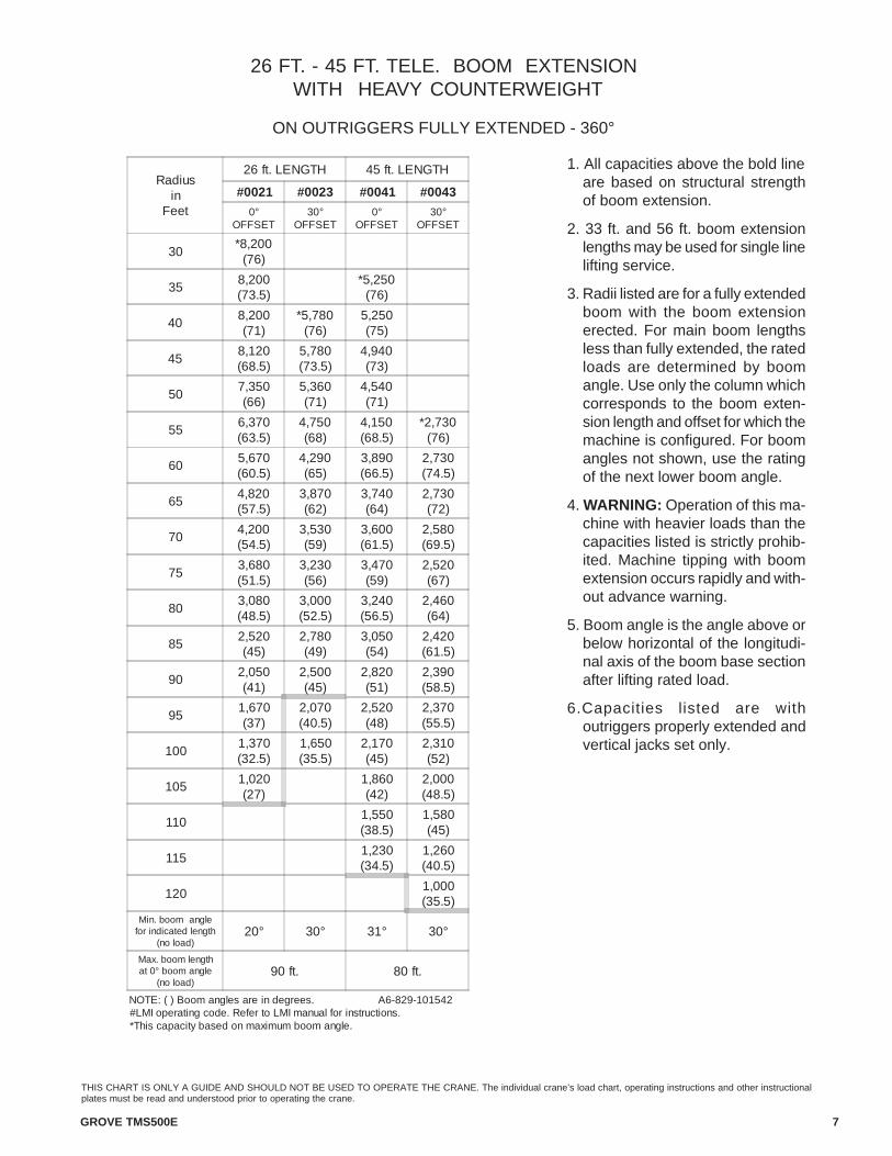
26 FT. - 45 FT. TELE. BOOM EXTENSION WITH HEAVY COUNTERWEIGHT
ON OUTRIGGERS FULLY EXTENDED - 360°
1. All capacities above the bold lineare based on structural strengthof boom extension.
2. 33 ft. and 56 ft. boom extensionlengths may be used for single linelifting service.
3. Radii listed are for a fully extendedboom with the boom extensionerected. For main boom lengthsless than fully extended, the ratedloads are determined by boomangle. Use only the column whichcorresponds to the boom exten-sion length and offset for which themachine is configured. For boomangles not shown, use the ratingof the next lower boom angle.
4. WARNING: Operation of this ma-chine with heavier loads than thecapacities listed is strictly prohib-ited. Machine tipping with boomextension occurs rapidly and with-out advance warning.
5. Boom angle is the angle above orbelow horizontal of the longitudi-nal axis of the boom base sectionafter lifting rated load.
6.Capacities listed are withoutriggers properly extended andvertical jacks set only.
Radiusin
Feet
26 ft. LENGTH 45 ft. LENGTH
#0021 #0023 #0041 #0043
0°OFFSET
30°OFFSET
0°OFFSET
30°OFFSET
30*8,200
(76)
358,200(73.5)
*5,250(76)
408,200(71)
*5,780(76)
5,250(75)
458,120(68.5)
5,780(73.5)
4,940(73)
507,350(66)
5,360(71)
4,540(71)
556,370(63.5)
4,750(68)
4,150(68.5)
*2,730(76)
605,670(60.5)
4,290(65)
3,890(66.5)
2,730(74.5)
654,820(57.5)
3,870(62)
3,740(64)
2,730(72)
704,200(54.5)
3,530(59)
3,600(61.5)
2,580(69.5)
753,680(51.5)
3,230(56)
3,470(59)
2,520(67)
803,080(48.5)
3,000(52.5)
3,240(56.5)
2,460(64)
852,520(45)
2,780(49)
3,050(54)
2,420(61.5)
902,050(41)
2,500(45)
2,820(51)
2,390(58.5)
951,670(37)
2,070(40.5)
2,520(48)
2,370(55.5)
1001,370(32.5)
1,650(35.5)
2,170(45)
2,310(52)
1051,020(27)
1,860(42)
2,000(48.5)
1101,550(38.5)
1,580(45)
1151,230(34.5)
1,260(40.5)
1201,000(35.5)
Min. boom anglefor indicated length
(no load)20° 30° 31° 30°
Max. boom lengthat 0° boom angle
(no load)90 ft. 80 ft.
NOTE: ( ) Boom angles are in degrees. A6-829-101542#LMI operating code. Refer to LMI manual for instructions.*This capacity based on maximum boom angle.
8 GROVE TMS500E
THIS CHART IS ONLY A GUIDE AND SHOULD NOT BE USED TO OPERATE THE CRANE. The individual crane’s load chart, operating instructions and other instructionalplates must be read and understood prior to operating the crane.
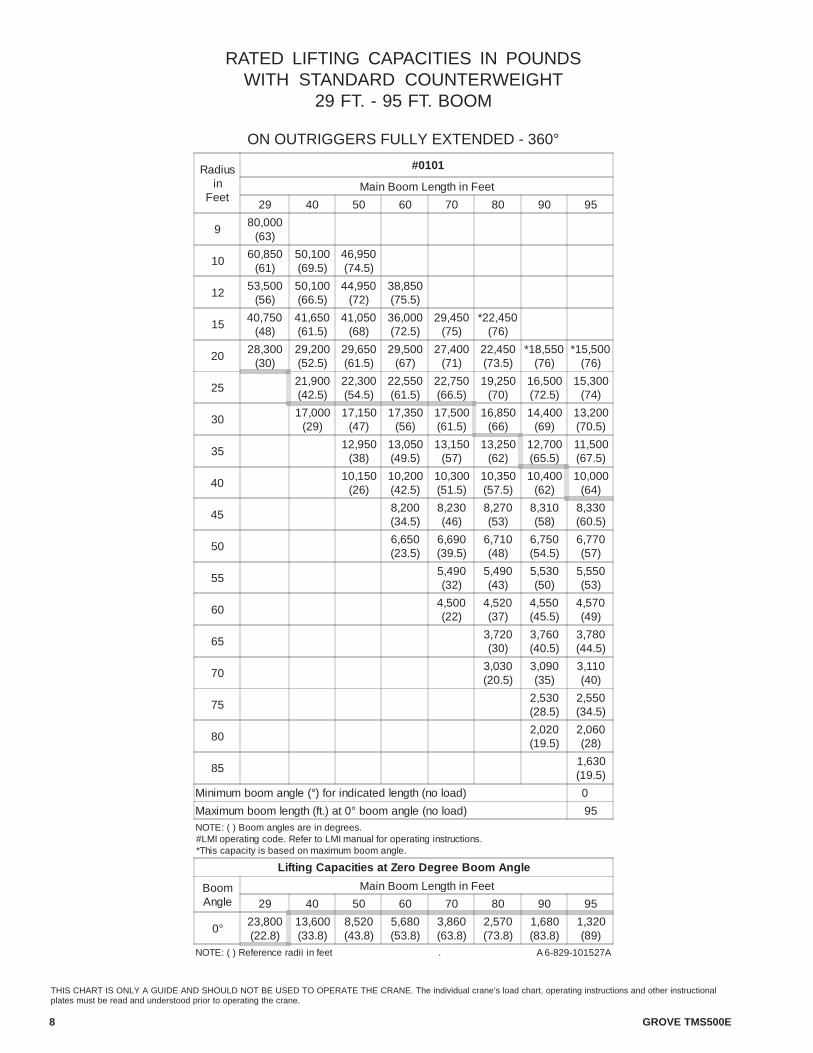
RATED LIFTING CAPACITIES IN POUNDSWITH STANDARD COUNTERWEIGHT
29 FT. - 95 FT. BOOM
ON OUTRIGGERS FULLY EXTENDED - 360°
Radiusin
Feet
#0101
Main Boom Length in Feet
29 40 50 60 70 80 90 95
980,000
(63)
1060,850
(61)50,100(69.5)
46,950(74.5)
1253,500
(56)50,100(66.5)
44,950(72)
38,850(75.5)
1540,750
(48)41,650(61.5)
41,050(68)
36,000(72.5)
29,450(75)
*22,450(76)
2028,300
(30)29,200(52.5)
29,650(61.5)
29,500(67)
27,400(71)
22,450(73.5)
*18,550(76)
*15,500(76)
2521,900(42.5)
22,300(54.5)
22,550(61.5)
22,750(66.5)
19,250(70)
16,500(72.5)
15,300(74)
3017,000
(29)17,150
(47)17,350
(56)17,500(61.5)
16,850(66)
14,400(69)
13,200(70.5)
3512,950
(38)13,050(49.5)
13,150(57)
13,250(62)
12,700(65.5)
11,500(67.5)
4010,150
(26)10,200(42.5)
10,300(51.5)
10,350(57.5)
10,400(62)
10,000(64)
458,200(34.5)
8,230(46)
8,270(53)
8,310(58)
8,330(60.5)
506,650(23.5)
6,690(39.5)
6,710(48)
6,750(54.5)
6,770(57)
555,490(32)
5,490(43)
5,530(50)
5,550(53)
604,500(22)
4,520(37)
4,550(45.5)
4,570(49)
653,720(30)
3,760(40.5)
3,780(44.5)
703,030(20.5)
3,090(35)
3,110(40)
752,530(28.5)
2,550(34.5)
802,020(19.5)
2,060(28)
851,630(19.5)
Minimum boom angle (°) for indicated length (no load) 0
Maximum boom length (ft.) at 0° boom angle (no load) 95NOTE: ( ) Boom angles are in degrees.#LMI operating code. Refer to LMI manual for operating instructions.*This capacity is based on maximum boom angle.
Lifting Capacities at Zero Degree Boom Angle
BoomAngle
Main Boom Length in Feet
29 40 50 60 70 80 90 95
0° 23,800(22.8)
13,600(33.8)
8,520(43.8)
5,680(53.8)
3,860(63.8)
2,570(73.8)
1,680(83.8)
1,320(89)
NOTE: ( ) Reference radii in feet . A 6-829-101527A
GROVE TMS500E 9
THIS CHART IS ONLY A GUIDE AND SHOULD NOT BE USED TO OPERATE THE CRANE. The individual crane’s load chart, operating instructions and other instructionalplates must be read and understood prior to operating the crane.
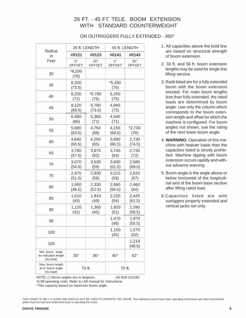
26 FT. - 45 FT. TELE. BOOM EXTENSION WITH STANDARD COUNTERWEIGHT
ON OUTRIGGERS FULLY EXTENDED - 360°
1. All capacities above the bold lineare based on structural strengthof boom extension.
2. 33 ft. and 56 ft. boom extensionlengths may be used for single linelifting service.
3. Radii listed are for a fully extendedboom with the boom extensionerected. For main boom lengthsless than fully extended, the ratedloads are determined by boomangle. Use only the column whichcorresponds to the boom exten-sion length and offset for which themachine is configured. For boomangles not shown, use the ratingof the next lower boom angle.
4. WARNING: Operation of this ma-chine with heavier loads than thecapacities listed is strictly prohib-ited. Machine tipping with boomextension occurs rapidly and with-out advance warning.
5. Boom angle is the angle above orbelow horizontal of the longitudi-nal axis of the boom base sectionafter lifting rated load.
6.Capacities listed are withoutriggers properly extended andvertical jacks set only.
Radiusin
Feet
26 ft. LENGTH 45 ft. LENGTH
#0121 #0123 #0141 #0143
0°OFFSET
30°OFFSET
0°OFFSET
30°OFFSET
30*8,200
(76)
358,200(73.5)
*5,250(76)
408,200(71)
*5,780(76)
5,250(75)
458,120(68.5)
5,780(73.5)
4,940(73)
506,980(66)
5,360(71)
4,540(71)
555,680(63.5)
4,750(68)
4,150(68.5)
*2,730(76)
604,640(60.5)
4,290(65)
3,890(66.5)
2,730(74.5)
653,780(57.5)
3,870(62)
3,740(64)
2,730(72)
703,070(54.5)
3,530(59)
3,600(61.5)
2,580(69.5)
752,470(51.5)
2,930(56)
3,210(59)
2,520(67)
801,950(48.5)
2,330(52.5)
2,680(56.5)
2,460(64)
851,510(45)
1,810(49)
2,220(54)
2,420(61.5)
901,120(41)
1,360(45)
1,820(51)
2,390(58.5)
951,470(48)
1,970(55.5)
1001,150(45)
1,570(52)
1051,210(48.5)
Min. boom anglefor indicated length
(no load)35° 36° 40° 42°
Max. boom lengthat 0° boom angle
(no load)70 ft. 70 ft.
NOTE: ( ) Boom angles are in degrees. A6-829-101543#LMI operating code. Refer to LMI manual for instructions.*This capacity based on maximum boom angle.

10 GROVE TMS500E
THIS CHART IS ONLY A GUIDE AND SHOULD NOT BE USED TO OPERATE THE CRANE. The individual crane’s load chart, operating instructions and other instructionalplates must be read and understood prior to operating the crane.
RATED LIFTING CAPACITIES IN POUNDSWITH LIGHT COUNTERWEIGHT
29 FT. - 95 FT. BOOM
ON OUTRIGGERS FULLY EXTENDED - 360°
Radiusin
Feet
#0201
Main Boom Length in Feet
29 40 50 60 70 80 90 95
972,450
(63)
1060,850
(61)50,100(69.5)
46,950(74.5)
1251,250
(56)50,100(66.5)
44,950(72)
38,850(75.5)
1539,000
(48)40,000(61.5)
40,350(68)
36,000(72.5)
29,450(75)
*22,450(76)
2027,000
(30)27,900(52.5)
28,300(61.5)
28,700(67)
27,400(71)
22,450(73.5)
*18,550(76)
*15,500(76)
2520,900(42.5)
21,400(54.5)
21,550(61.5)
22,050(66.5)
19,250(70)
16,500(72.5)
15,300(74)
3015,150
(29)15,200
(47)15,250
(56)15,550(61.5)
15,850(66)
14,400(69)
13,200(70.5)
35 11,500
(38)11,450(49.5)
11,650(57)
11,850(62)
11,850(65.5)
11,500(67.5)
409,010(26)
8,970(42.5)
9,080(51.5)
9,190(57.5)
9,210(62)
9,220(64)
457,170(34.5)
7,230(46)
7,280(53)
7,300(58)
7,320(60.5)
505,800(23.5)
5,830(39.5)
5,840(48)
5,870(54.5)
5,880(57)
554,750(32)
4,730(43)
4,760(50)
4,770(53)
603,860(22)
3,840(37)
3,870(45.5)
3,880(49)
653,110(30)
3,140(40.5)
3,150(44.5)
702,470(20.5)
2,530(35)
2,550(40)
752,010(28.5)
2,030(34.5)
801,550(19.5)
1,590(28)
851,190(19.5)
Minimum boom angle (°) for indicated length (no load) 0
Maximum boom length (ft.) at 0° boom angle (no load) 95NOTE: ( ) Boom angles are in degrees.#LMI operating code. Refer to LMI manual for operating instructions.*This capacity is based on maximum boom angle.
Lifting Capacities at Zero Degree Boom Angle
BoomAngle
Main Boom Length in Feet
29 40 50 60 70 80 90
0° 22,650(22.8)
12,100(33.8)
7,540(43.8)
4,940(53.8)
3,280(63.8)
2,050(73.8)
1,240(83.8)
NOTE: ( ) Reference radii in feet . A6-829-101535A
GROVE TMS500E 11
THIS CHART IS ONLY A GUIDE AND SHOULD NOT BE USED TO OPERATE THE CRANE. The individual crane’s load chart, operating instructions and other instructionalplates must be read and understood prior to operating the crane.
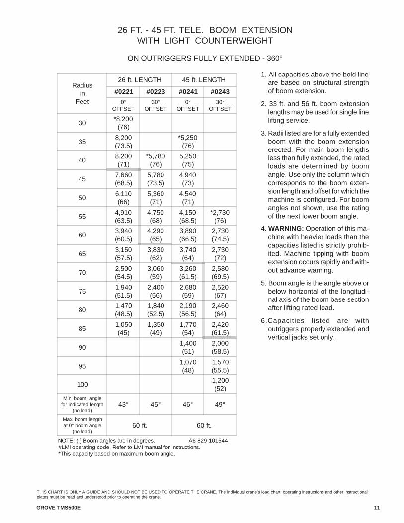
26 FT. - 45 FT. TELE. BOOM EXTENSIONWITH LIGHT COUNTERWEIGHT
ON OUTRIGGERS FULLY EXTENDED - 360°
1. All capacities above the bold lineare based on structural strengthof boom extension.
2. 33 ft. and 56 ft. boom extensionlengths may be used for single linelifting service.
3. Radii listed are for a fully extendedboom with the boom extensionerected. For main boom lengthsless than fully extended, the ratedloads are determined by boomangle. Use only the column whichcorresponds to the boom exten-sion length and offset for which themachine is configured. For boomangles not shown, use the ratingof the next lower boom angle.
4. WARNING: Operation of this ma-chine with heavier loads than thecapacities listed is strictly prohib-ited. Machine tipping with boomextension occurs rapidly and with-out advance warning.
5. Boom angle is the angle above orbelow horizontal of the longitudi-nal axis of the boom base sectionafter lifting rated load.
6.Capacities listed are withoutriggers properly extended andvertical jacks set only.
Radiusin
Feet
26 ft. LENGTH 45 ft. LENGTH
#0221 #0223 #0241 #0243
0°OFFSET
30°OFFSET
0°OFFSET
30°OFFSET
30*8,200
(76)
358,200(73.5)
*5,250(76)
408,200(71)
*5,780(76)
5,250(75)
457,660(68.5)
5,780(73.5)
4,940(73)
506,110(66)
5,360(71)
4,540(71)
554,910(63.5)
4,750(68)
4,150(68.5)
*2,730(76)
603,940(60.5)
4,290(65)
3,890(66.5)
2,730(74.5)
653,150(57.5)
3,830(62)
3,740(64)
2,730(72)
702,500(54.5)
3,060(59)
3,260(61.5)
2,580(69.5)
751,940(51.5)
2,400(56)
2,680(59)
2,520(67)
801,470(48.5)
1,840(52.5)
2,190(56.5)
2,460(64)
851,050(45)
1,350(49)
1,770(54)
2,420(61.5)
901,400(51)
2,000(58.5)
951,070(48)
1,570(55.5)
1001,200(52)
Min. boom anglefor indicated length
(no load)43° 45° 46° 49°
Max. boom lengthat 0° boom angle
(no load)60 ft. 60 ft.
NOTE: ( ) Boom angles are in degrees. A6-829-101544#LMI operating code. Refer to LMI manual for instructions.*This capacity based on maximum boom angle.

GVW Front Rearlbs kg lbs kg lbs kg
Axle/Tire Allowable Weights 62,000 28,123 21,000 9,526 41,000 18,598
TMS500E Basic Machine with main hoist w/ 50,848 23,065 17,709 8,033 33,139 15,032rope, 26-45 ft. tele swingaway, standardcounterweight 2,630 lbs. (1 193 kg)
ADD: Heavy counterweight package 6,160 2,794 -152 -69 6,312 2,863
ADD: 25 Ton, 3 sheave, hookblock (front 550 249 755 342 -205 -93stowage)ADD: 7.5 Ton, headache ball (front stowage) 300 136 413 187 -113 -51ADD: Aux Hoist w/rope 1,101 499 -530 -240 1,631 740ADD: Aux boom nose 114 52 165 75 -51 -23ADD: 200 lb. driver 200 91 241 109 -41 -19ADD: A/C carrier 81 37 94 43 -13 -6ADD: A/C superstructure 205 93 -47 -21 252 114SUB: 1/2 tank of fuel -213 -97 -162 -73 -51 -23Remove: 26-46 ft. tele swingaway only -1,790 -812 -1,351 -613 -439 -199Remove total counterweight: which includestotal front bumper shell and superstructurecounterweight inserts from basic machine forweight reduction. -1,380 -626 29 13 -1,409 -639
12 GROVE TMS500E
THIS CHART IS ONLY A GUIDE AND SHOULD NOT BE USED TO OPERATE THE CRANE. The individual crane’s load chart, operating instructions and other instructionalplates must be read and understood prior to operating the crane.
Counterweight Configurations
Heavy:Superstructure 7000 lb. + 1790 lb. Front Bumper with Aux. Hoistor in place of (IPO).
Standard:Superstructure 2300 lb. + 330 lb. Front Bumper Shell with Aux.Hoist or in place of (IPO).
Light:Superstructure Shell 1250 lb. + No Front Bumper without Aux.Hoist or in place of (IPO).
Note: Weights may vary due to manufacturing tolerances.
Grove Worldwide - WorldHeadquartersWestern Hemisphere, Asia/Pacific1565 Buchanan Trail East P.O. Box 21 Shady Grove, Pennsylvania 17256-0021,USATel: [Int + 1] (717) 597-8121Fax: [Int + 1] (717) 597-4062
Grove Europe Limited*Europe, Africa, Middle East (Sales & Marketing)1 Emperor WayDoxford International Business ParkSunderland SR3 3XR, England Tel: [Int + 44] (191) 515-7253Fax: [Int + 44] (191) 564-0442
Deutsche Grove GmbHGermany (Sales & Service)Helmholtzstrasse 12, Postfach 5026D-40750 Langenfeld, GermanyTel: [Int + 49] (2173) 8909-0Fax: [Int + 49] (2173) 8909-30
Deutsche Grove GmbH Wilhelmshaven WorksIndustriegelande West, Postfach 1853D-26358 Wilhelmshaven, Germany Tel: [Int + 49] (4421) 294-0Fax: [Int + 49] (4421) 294-301
Grove France SASFrance (Sales & Service)16, Chaussèe Jules-Cèsar, 95520OSNYB.P. 203, 95523 Cergy PontoiseFranceTel: [Int + 33] (1) 303-13150Fax: [Int + 33] (1) 303-86085
Grove Asia/Pacific - RepresentativeOffice Asia/Pacific, Near East171 Chin Swee Road#10-09 San Centre Singapore 16987Tel: [Int + 65] 536-6112 Fax: [Int + 65] 536-6119
Grove China - Representative OfficeRoom 713, Towercrest PlazaNo. 3 Mai Zi Dian West RoadChao Yang DistrictBeijing, China 100016Tel: [Int + 86] (10) 64 67 16 90Fax: [Int + 86] (10) 64 67 16 91
Grove Middle East P.O. Box 290Dubai, United Arab EmiratesTel: [Int + 971] (4) 3484478Fax: [Int + 971] (4) 3484478
Lifetime Customer SupportWestern Hemisphere, Asia/Pacific 1086 Wayne AvenueChambersburg, Pennsylvania 17201USATel: [Int + 1] (717) 263-5100Fax: [Int + 1] (717) 267-0404
Europe, Africa, Middle EastGrove Europe Limited*1 Emperor WayDoxford International Business ParkSunderland SR3 3XR, England Tel: [Int + 44] (191) 565-6281Parts Fax: [Int + 44] (191) 515-7475Service Fax: [Int + 44] (191) 515-7340
*Grove Europe Limited, Registered in England,Number 1845128.
Form No.: TMS500E Part No.: 01-131 0201-4M Printed in U.S.A.
Constant improvement and engineering progress make it necessary that we reserve the right to makespecification, equipment, and price changes without notice. Illustrations shown may include optionalequipment and accessories and may not include all standard equipment.
http://www.groveworldwide.com
Distributed By:
GROVE® and GROVE LOGO are registered trademarks of GROVE in the U.S. and/or other countries.Copyright© 2000 GROVE. All rights reserved.


![Untitled-1 [] · Series 500D: National Telescoping Crane America's Leading Manufacturer of Truck-Mounted Hydraulic Cranes. 500D NATIONAL CRANE A Grove Worldwide Company](https://img.dokumen.tips/doc/110x75/5b56c8087f8b9a3f7e8ce125/untitled-1-series-500d-national-telescoping-crane-americas-leading-manufacturer.jpg)