Embed Size (px)
Citation preview

REFERENCEMANUAL
S TA N D B Y G E N E R AT O R S
Troubleshooting and DiagnosticsWireless Monitoring Systems
®
Wireless Remote
Wireless Advanced Module
Wireless Local Monitor
Mobile Link™
Mobile Link™ Wi-Fi
ii Diagnostic Repair Manual
SafetyThroughout this publication and on tags and decalsaffixed to the generator, DANGER, WARNING, andCAUTION blocks are used to alert personnel to specialinstructions about a particular operation that may behazardous if performed incorrectly or carelessly. Observethem carefully. Their definitions are as follows:
NOTE: Notes provide additional information important toa procedure or component.
These safety alerts cannot eliminate the hazards theyindicate. Observing safety precautions and strictcompliance with the special instructions while performingthe action or service are essential to preventingaccidents.
Read This Manual ThoroughlyThis diagnostic manual has been written and publishedby Generac to aid qualified Generac dealer techniciansand company service personnel when servicing theproducts described herein.
It is assumed that these personnel are familiar with theservicing procedures for these products, or like or similarproducts manufactured and marketed by Generac, andthat they have been trained in the recommendedservicing procedures for these products, including theuse of common hand tools and any special Generac toolsor tools from other suppliers.
Generac could not possibly know of and advise theservice trade of all conceivable procedures by which aservice might be performed and of the possible hazardsand/or results of each method. We have not undertakenany such wide evaluation. Therefore, anyone who uses aprocedure or tool not recommended by Generac mustfirst satisfy themselves that neither his nor the productssafety will be endangered by the service procedureselected.
All information, illustrations and specifications in thismanual are based on the latest product informationavailable at the time of publication.
When working on these products, remember that theelectrical system and engine ignition system are capableof violent and damaging short circuits or severe electricalshocks. If you intend to perform work where electricalterminals could be grounded or touched, the batterycables should be disconnected at the battery.
Any time the intake or exhaust openings of the engineare exposed during service, they should be covered toprevent accidental entry of foreign material. Entry of suchmaterials will result in extensive damage when theengine Is started.
During any maintenance procedure, replacementfasteners must have the same measurements andstrength as the fasteners that were removed. Metric boltsand nuts have numbers that indicate their strength.Customary bolts use radial lines to indicate strengthwhile most customary nuts do not have strengthmarkings. Mismatched or incorrect fasteners can causedamage, malfunction and possible injury.
(000001)
DANGERIndicates a hazardous situation which, if not avoided, will result in death or serious injury.
(000002)
WARNINGIndicates a hazardous situation which, if not avoided,could result in death or serious injury.
(000003)
CAUTIONIndicates a hazardous situation which, if not avoided,could result in minor or moderate injury.
(000393a)
WARNINGCANCER AND REPRODUCTIVE HARM
www.P65Warnings.ca.gov.

Table of Contents
Safety ........................................................................ ii
Read This Manual Thoroughly .................................. ii
Section 1 Wireless Remote and Mobile Link™........1
Wireless Monitor .......................................................1
Wireless Basic Troubleshooting ................................1
Wireless Advanced Module ......................................2
Wireless Advanced Features ....................................2
Wireless Advanced Troubleshooting ........................2
Mobile Link™ ............................................................3
Diagnosing Mobile Link Communication to Controller ..............................................................4
Wireless Local Monitor ..............................................4
Wireless Local Monitor General Operation ...............5
Troubleshooting ........................................................7
Quick Reference Chart .............................................8
Section 2 Mobile Link™Wi-Fi Module.......................9
Pre-Installation Signal Strength Test ........................9
Connect to Home Network ........................................9
Before Starting ..........................................................9
Wi-Fi Setup at Generator Controller .........................9
Unsuccessful Network Connection .........................16
Download Mobile Link and Complete Registration .22
Disable Wi-Fi ...........................................................22
Reset Wi-Fi to Factory Default Settings ..................22
Wi-Fi Troubleshooting .............................................23
Diagnosing Wi-Fi Communication to Controller ......24
WiFi Module Voltage Tests .....................................24
Terms and Acronyms ..............................................25
Diagnostic Repair Manual iii

Table of Contents
This page intentionally left blank.
Diagnostic Repair Manual iv

Section 1 Wireless Remote and Mobile Link™
Wireless MonitorSee Figure 1-1. This wireless device provides threebasic alerts indicated by colored LEDs.
Green LED (A) – Generator OK indicates one of thefollowing conditions:
• The controller on the generator is set to AUTO, noalarms are present. The generator is ready to startand run or is running.
• The controller on the generator is set to Manual.The engine is running and no alarms are active.
When active, the green LED will flash once every 10seconds.
Yellow LED (B) – Maintenance Needed indicates thateither a Generator Warning is present or generatormaintenance is required. The generator will not beprevented from running when the yellow LED is on.When active, the yellow LED will flash once every two (2)seconds.
Red LED (C) – Contact Dealer indicates any one of thefollowing conditions:
• The controller on the generator is set to Off.
• The generator has not been registered.
• A Generator Alarm is present.
• The controller has been powered up, but theInstallation Wizard procedure has not beencompleted.
Figure 1-1. Wireless Monitor
If a generator alarm is present the generator will not startand run in the event of a utility loss, or will beautomatically shut down if the engine is already running.When active, the red LED will flash once every second.
The internal buzzer will sound once every 30 secondswhen the red LED is on. The buzzer can be silenced bybriefly pressing and releasing the Pair/Reset button; the
buzzer will pulse twice to indicate it has been silenced.The buzzer will not reactivate until a new alarm has beendetected.
The wireless monitor display unit updates the status of itsLED's every 30 to 60 seconds. To conserve power andextend battery life, the LEDs are not lit continuously:instead they are briefly flashed as indicated above.
Wireless Basic Troubleshooting
Pairing the Generator Transceiver with the Display Unit
See Figure 1-1 for the location of the “Pair/Reset” button(D) on the display unit.
1. Place the display unit against the generatortransceiver as shown in Figure 1-2, thenimmediately press and hold the “Pair/Reset” buttonon the display unit.
Figure 1-2. Place the Display Unit Against the Generator Transceiver
2. The yellow LED will begin flashing after about threeseconds, indicating the modules are in pairingmode. Release the “Pair/Reset” button on thedisplay unit and move the display unit away fromthe generator transceiver.
3. The Yellow LED will continue to flash during thepairing process.
4. Once the two modules have been successfullypaired the yellow LED will stop flashing and thegreen LED will begin flashing.
5. Press and release the Pair/Reset button tocomplete the pairing process. At this time thegreen LED will stop flashing and the display unitwill enter its normal mode of operation.
C
A
B
D
002456
002457
Troubleshooting and Diagnostics Wireless Monitoring Systems 1

Section 1 Wireless Remote and Mobile Link™
NOTE: If the controller is still set to OFF the red LED willbegin to flash, indicating the generator is in Alarm Mode.Do not confuse this flashing red LED with Failure To Pair described below.
NOTE: The magnets in the display unit activate amagnetic reed switch in the generator transceiver in Step1. The relative positioning of the two units needs to be asshown in Figure 1-2 to activate the magnetic reed switch.
Failure To Pair
If the two modules fail to pair up within 30 seconds, theyellow LED will stop flashing and the red LED will beginto flash. If this happens proceed as follows:
1. Press and release the Pair/Reset button to stop thered LED from flashing.
2. Verify that good non-rechargeable AAA 1.5Vbatteries are installed.
3. Check the wiring to make sure all the plugs arefully inserted.
4. Repeat the pairing process from Step 1.
Results
1. If the link is established, discontinue troubleshoot-ing.
2. If the link continues to fail, replace the wirelessremote and transmitter.
Wireless Advanced ModuleThe wireless display system consists of a wirelesstransmitter and a remote monitor display. The system hasa “line of sight” range of about 300 feet but this will bereduced if the signal must go through walls, floors, etc.
Figure 1-3. Wireless Advanced Module
NOTE: Some building materials may completely blockthe passage of the signal. For example: steel beams,metal siding, foil radiant barrier insulation.
The display is intended to show the status of thegenerator and to give warning if the system is in an alarmstate. It also provides the following functions:
• Permanent time/date stamped history of generatoralarms.
• Allows for remote testing of generator start andtransfer functions (when utility power is present).
• Facility to set an exercise time and day from thedisplay.
• A separate battery backed clock (with date) whichis synchronized to the generator clock. If power isremoved from the generator, the time and date willautomatically be restored from this clock.
• Ability to add extra displays.
• Graphing capability for trending of Engine RPM,Utility Voltage and Battery Voltage.
Wireless Advanced FeaturesOne of the most commonly used features on the deviceis the ability to test the functions of the generator. The“TEST” menu provides the option to remotely start, startand transfer, and stop the generator. This feature onlyworks when Utility voltage is available and the controlleris set to AUTO.
NOTE: The remote cannot disable or prevent thegenerator from running. The only method to disable thegenerator is by cycling the controller the OFF.
Some operational rules apply when using the “TEST”feature and are not due to product failure:
• The generator can only be shutdown if it wasstarted via the remote. It will not respond to thecommand if running in a Utility failure.
• When the command has been given for a start andtransfer to occur the generator will stay runninguntil the “STOP” command has been given. Thegenerator will then run for a 1 minute cool downperiod.
Wireless Advanced Troubleshooting
Resynchronizing the Radio After Battery Disconnection or In the Event of Loss of Communication
If the battery is ever disconnected from the generator, theradio system will stop working and will not automaticallyresynchronize. To resynchronize the system, follow thesteps shown below:
1. Verify the display unit has working batteries.
2. Turn the display unit off using the slide switch onthe side of the unit.
3. Take the display unit to the generator.
002458
2 Troubleshooting and Diagnostics Wireless Monitoring Systems
Section 1 Wireless Remote and Mobile Link™
4. Open the generator lid and set the generatorcontroller to OFF.
5. Remove the enclosure panel from the front of thegenerator enclosure.
6. Locate and disconnect the radio connector underthe generator display panel.*
NOTE: *The radio connector has a white connector withgray cable. Remove the connector by squeezing thelocking tab and pulling the connector down. Carefully usea pliers if necessary.
7. Turn on the display unit and navigate to the RADIOmenu.
8. Select “RESET RADIO” and immediately (within 5seconds) put the connector back into the controller(removed in Step 6).
The display unit will begin searching for the generator. Upto one minute will pass while the remote unit andgenerator synchronize. Once the generator is found, theradio link is established and the settings will beremembered.
9. Install the front enclosure panel and close the lid.
10. Set the controller to AUTO.
11. Return the display unit to its original location andconnect it to the wall transformer.
12. Turn it off and back on again. (this is just to get itout of sleep mode which it may have entered onbattery power).
Results
1. If the link is established, discontinue troubleshoot-ing.
2. If the link fails to establish, repeat Steps 6-8 using adifferent channel.
3. If the link continues to fail, replace the wirelessremote and transmitter.
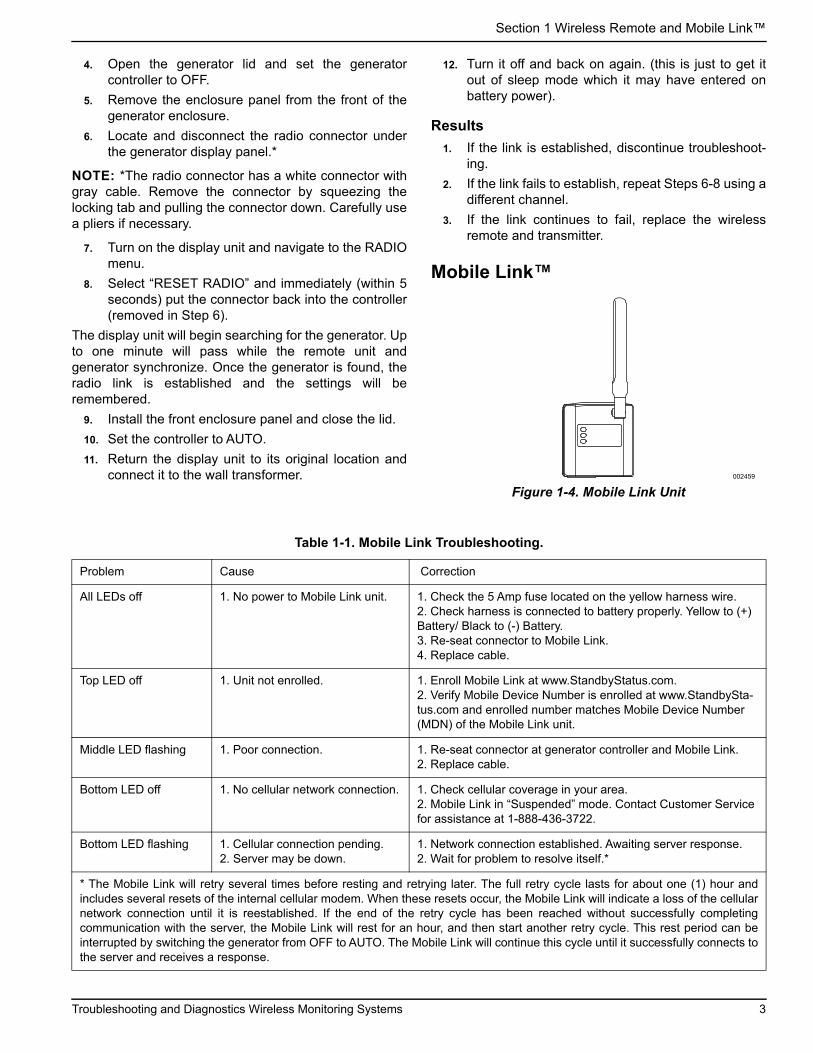
Mobile Link™
Figure 1-4. Mobile Link Unit002459
Table 1-1. Mobile Link Troubleshooting.
Problem Cause Correction
All LEDs off 1. No power to Mobile Link unit. 1. Check the 5 Amp fuse located on the yellow harness wire.2. Check harness is connected to battery properly. Yellow to (+) Battery/ Black to (-) Battery.3. Re-seat connector to Mobile Link.4. Replace cable.
Top LED off 1. Unit not enrolled. 1. Enroll Mobile Link at www.StandbyStatus.com.2. Verify Mobile Device Number is enrolled at www.StandbySta-tus.com and enrolled number matches Mobile Device Number (MDN) of the Mobile Link unit.
Middle LED flashing 1. Poor connection. 1. Re-seat connector at generator controller and Mobile Link.2. Replace cable.
Bottom LED off 1. No cellular network connection. 1. Check cellular coverage in your area.2. Mobile Link in “Suspended” mode. Contact Customer Service for assistance at 1-888-436-3722.
Bottom LED flashing 1. Cellular connection pending.2. Server may be down.
1. Network connection established. Awaiting server response.2. Wait for problem to resolve itself.*
* The Mobile Link will retry several times before resting and retrying later. The full retry cycle lasts for about one (1) hour andincludes several resets of the internal cellular modem. When these resets occur, the Mobile Link will indicate a loss of the cellularnetwork connection until it is reestablished. If the end of the retry cycle has been reached without successfully completingcommunication with the server, the Mobile Link will rest for an hour, and then start another retry cycle. This rest period can beinterrupted by switching the generator from OFF to AUTO. The Mobile Link will continue this cycle until it successfully connects tothe server and receives a response.
Troubleshooting and Diagnostics Wireless Monitoring Systems 3

Section 1 Wireless Remote and Mobile Link™
Diagnosing Mobile Link Communication to ControllerA flashing middle LED on the Mobile Link controllerindicates a loss of communication between the MobileLink unit and the generator controller.
The problem can be the generator controller, the MobileLink controller, or the harness between the two units.
To determine the problem, perform voltage checksaccording to the charts below. This will help determinewhether the Mobile Link controller or the generatorcontroller is at fault.
Three wires are used to communicate between theMobile Link controller and the generator controller. TheSHLD wire is connected to the Mobile Link controlleronly. There are two communication wires (Wires 387 and388) connected between the two controllers.
First, verify that the harness is plugged in correctly andthat the generator starts and runs properly. If the harnessis plugged in correctly and there is still nocommunication, disconnect both ends of the harness.Perform a continuity test on the wires in the harness toverify that they are not shorted between one another, andthere are no opens except for the shield wire, which isconnected to the Mobile Link connector only.
There are four charts. Charts 1 and 2 are used with allconnectors connected while back probing each wire tobattery ground (-) and to battery positive (+).
Charts 3 and 4 determine the voltage output from eachunit while the other end of the harness is disconnected.
Figure 1-5. Mobile Link Connector
If all LEDs are on and Mobile Link is communicatingnormally, then the power wire (13A), ground wire (0), andfuse to the Mobile Link unit are good.
If no LEDs are illuminated on the Mobile link unit, verifythat the power wire (13A), ground wire (0), and fuse tothe Mobile Link Unit are good.
Wireless Local MonitorThe Wireless Local Monitor consists of one transceiver,mounted on the generator, and a display unit, placed in aconvenient viewing location within the home or business.The system has a “line of sight” range of about 600 feet,but this will be reduced when the signal must passthrough walls, floors, etc. With this remote monitoringsystem, the status of the generator can be checkedeasily from within the home or business.
The generator transceiver and display unit are shippedfrom the factory paired. These units are pre-paired toensure communication and prevent cross-communication from other devices in the area.
Chart 1 – Back Probe at Mobile Link connector
(All connectors plugged in) All voltages +/- 0.5 volts
DM Negative lead on Battery NEG
DM Positive lead on Battery POS
Pin 1, Wire SHLD 0 VDC Battery Voltage
Pin 2, Wire 388 - 4.2 to - 5.6 VDC Fluctuating
18.0 to 19.2 VDC Fluctuating
Pin 3, EMPTY EMPTY EMPTY
Pin 4, Wire 0 0 VDC Battery Voltage
Pin 5, Wire 387 -5.8 to -6.8 VDC Fluctuating
22.33 VDC
Pin 6, Wire 13A Battery Voltage 0 VDC
6 5
3 2
4
1
4 3
8 7
2
6
1
5
002460
Chart 2 – Back Probe at Evolution Controller
(All connectors plugged in) All voltages +/- 0.5 volts
DM Negative lead on Battery NEG
DM Positive lead on Battery POS
Pin 7, Wire 388 4.4 to - 5.3 VDC Fluctuating
18.3 to 19.4 VDC Fluctuating
Pin 8, Wire 387 6.0 to - 6.8 VDC Fluctuating
19.8 to 20.5 VDC Fluctuating
Chart 3 – Back Probe at Mobile Link connector
(Mobile Link connector unplugged) All voltages +/- 0.5 volts
DM Negative lead on Battery NEG
DM Positive lead on Battery POS
Pin 1, Wire SHLD 0 VDC 0 VDC
Pin 2, Wire 388 0 VDC Battery Voltage
Pin 3, EMPTY EMPTY EMPTY
Pin 4, Wire 0 0 VDC Battery Voltage
Pin 5, Wire 387 - 8.56 VDC 22.33 VDC
Pin 6, Wire 13A Battery Voltage 0 VDC
If no voltages are indicated based on this chart the controller is at fault.
Chart 4 – Back Probe at Evolution Controller
(Mobile link plugged in Evolution connector unplugged) Allvoltages +/- 0.5 volts
DM Negative lead on Battery NEG
DM Positive lead on Battery POS
Pin 7, Wire 388 - 5.5 VDC 19.3 VDC
Pin 8, Wire 387 0 VDC Battery Voltage
If no voltages are indicated based on this chart the Mobile Link unit is at fault.
4 Troubleshooting and Diagnostics Wireless Monitoring Systems

Section 1 Wireless Remote and Mobile Link™
NOTE: Some building materials may completely blockthe passage of the signal, for example, steel beams,metal siding and foil radiant barrier insulation.
• The Wireless Local Monitor indicates the generatorstatus via three lights - Green, Yellow or Red.
• The Test button performs a Signal Strength Test.
• The Battery Status Indicator provides low batterystatus.
• The Buzzer gives audible warnings in conjunctionwith Yellow or Red lights.
Figure 1-6. Wireless Local Monitor Functions
Generator Compatibility
• This unit can be installed on all 2008 and later air-cooled home standby units with an LCD displayand all 2010 and later liquid-cooled gaseous fuelstandby units. The unit can also be used on 2013and later Evolution controlled liquid-cooled dieselfuel standby units.
• For liquid-cooled units, an additional adapterharness is required (model 006665-0).
• Maximum ambient temperature rating: 122 °F / 50 °C.
Signal Strength Test
The display unit is equipped with a Signal Strength TestMode. Press the Test button for five (5) seconds to enterthe Signal Strength Test Mode. The Green, Yellow andRed lights will alternately light for a short period toindicate transition from Status mode to the SignalStrength Test Mode. The unit will be in this mode for 30seconds. During the Signal Strength Test:
• Green - Good Signal Strength
• Yellow - Marginal Signal Strength
• Red - No Signal Strength
After 30 seconds, the unit will automatically exit theSignal Strength Test Mode. When this happens, theindicators alternately light to signal the transition back toStatus Mode.
NOTE: Extended or frequent use of the Signal StrengthTest may deplete battery life.
NOTE: The display unit will still work if the signalstrength is yellow but battery life may be reduced.
Signal Strength Test Quick Reference Chart
Signal Strength Test is active - Display unit button mustbe pressed for more than 5 seconds - Display unit lightswill go from providing current generator status to arotating light pattern to signal a change in function to aSignal Strength Test Mode. It will repeat the rotating lightpattern when it exits Signal Strength Test Mode.
Wireless Local Monitor General OperationThe normal state of the display unit is to have no lightsactive. This indicates that the generator has no problems.When any problems occur, the lights will indicate theproblem based on the information in this section.
Generator Transceiver Status Light
• The generator transceiver has a green status lightthat indicates it has power and is communicatingwith the display unit. This light can be viewedinside the generator compartment, through the wireloom opening when the generator lid is raised.
• Solid light Green light - power present /communication established
• Flashing Green light - power present / nocommunication
Display Unit Green Light (Generator OK or Running)
During normal operation, if the generator is in AUTO anddoes not have any maintenance actions, warnings oralarms active, no lights will be illuminated.
A. Test Button
B. Buzzer - sounds with Yellow or Red Lights
C. Battery Status Indicator
D. Green Light - Generator OK / generator operates
E. Yellow Light - Warning or Maintenance required / generator operates
F. Red Light - Alarm / generator shuts down
D
A
FEC
B
002461 Green Light
Yellow Light
Red Light
Meaning
ON OFF OFFStrong signal from Transceiver unit to Display unit.
OFF ON OFFWeak signal from Transceiver to Display unit.
OFF OFF ONNo signal from Transceiver to Base unit.
Troubleshooting and Diagnostics Wireless Monitoring Systems 5
Section 1 Wireless Remote and Mobile Link™
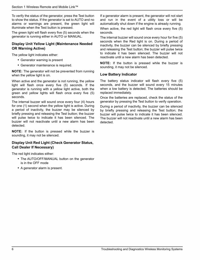
To verify the status of the generator, press the Test buttonto show the status. If the generator is set to AUTO and noalarms or warnings are present, the green light willilluminate when the Test button is pressed.
The green light will flash every five (5) seconds when thegenerator is running either in AUTO or MANUAL.
Display Unit Yellow Light (Maintenance Needed OR Warning Active)
The yellow light indicates either:
• Generator warning is present
• Generator maintenance is required.
NOTE: The generator will not be prevented from runningwhen the yellow light is on.
When active and the generator is not running, the yellowlight will flash once every five (5) seconds. If thegenerator is running with a yellow light active, both thegreen and yellow lights will flash once every five (5)seconds.
The internal buzzer will sound once every four (4) hoursfor one (1) second when the yellow light is active. Duringa period of inactivity, the buzzer may be silenced bybriefly pressing and releasing the Test button; the buzzerwill pulse twice to indicate it has been silenced. Thebuzzer will not reactivate until a new alarm has beendetected.
NOTE: If the button is pressed while the buzzer issounding, it may not be silenced.
Display Unit Red Light (Check Generator Status, Call Dealer If Necessary)
The red light indicates either:
• The AUTO/OFF/MANUAL button on the generatoris in the OFF mode
• A generator alarm is present.
If a generator alarm is present, the generator will not startand run in the event of a utility loss or will beautomatically shut down if the engine is already running.
When active, the red light will flash once every five (5)seconds.
The internal buzzer will sound once every hour for five (5)seconds when the Red light is on. During a period ofinactivity, the buzzer can be silenced by briefly pressingand releasing the Test button; the buzzer will pulse twiceto indicate it has been silenced. The buzzer will notreactivate until a new alarm has been detected.
NOTE: If the button is pressed while the buzzer issounding, it may not be silenced.
Low Battery Indicator
The battery status indicator will flash every five (5)seconds, and the buzzer will sound every 15 minuteswhen a low battery is detected. The batteries should bereplaced immediately.
Once the batteries are replaced, check the status of thegenerator by pressing the Test button to verify operation.
During a period of inactivity, the buzzer can be silencedby briefly pressing and releasing the Test button; thebuzzer will pulse twice to indicate it has been silenced.The buzzer will not reactivate until a new alarm has beendetected.
6 Troubleshooting and Diagnostics Wireless Monitoring Systems

Section 1 Wireless Remote and Mobile Link™
Troubleshooting
Problem Possible Causes Possible Corrective Actions
Generator transceiver light not illuminated
The transceiver is not receiving power. Connection to generator transceiver may not be made.
Check for proper harness transceiver connection at the transceiver and controller.
The transceiver is not receiving power. Fuse has failed, been damaged or is removed from generator controller.
Check and replace fuse.
The transceiver is not receiving power. Generator battery is disconnected.
Check generator battery connections.
Generator transceiver light flashing The transceiver is not in communication with the display unit.
Install or replace batteries.Display unit may be out of range.
Display unit – Yellow and Red lights are flashing
The generator transceiver is not communicating with the generator.
Check the wiring harness and connections between the Generator control panel and the transceiver.
Problem Possible Causes Possible Corrective Actions
Display Unit – All lights flashing (Communication lost between Generator Transceiver and Display unit)
Display unit is out of range with generator transceiver.
Check range status by performing Signal Strength Test – move display unit closer to generator until range is acceptable.
Generator transceiver is not communicating with generator controller or is not receiving power.
Check for proper connection to transceiver.
Check for proper connection to controller.
The transceiver is not receiving power. Fuse has failed, been damaged or is removed from generator controller.
Check and replace fuse.
The transceiver is not receiving power. Generator battery is disconnected.
Check generator battery connections.
Display Unit – No lights illuminate when button pressed
Dead batteries. Check and replace batteries.
Battery – Battery life is less than expected
Low signal strength. Perform Signal Strength Test and relocate to a location with higher signal strength, if necessary.
Low signal strength Signal reduced due to travel through various mediums, such as, metal siding, tinted or filtered windows, brick, multiple walls or atmospheric conditions.
Perform Signal Strength Test and relocate to a location with higher signal strength, if necessary.
Troubleshooting and Diagnostics Wireless Monitoring Systems 7
Section 1 Wireless Remote and Mobile Link™
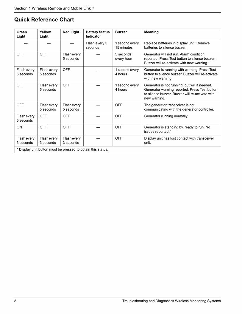
Quick Reference Chart
Green Light
Yellow Light
Red Light Battery Status Indicator
Buzzer Meaning
— — — Flash every 5 seconds
1 second every 15 minutes
Replace batteries in display unit. Remove batteries to silence buzzer.
OFF OFF Flash every 5 seconds
— 5 seconds every hour
Generator will not run. Alarm condition reported. Press Test button to silence buzzer. Buzzer will re-activate with new warning.
Flash every 5 seconds
Flash every 5 seconds
OFF — 1 second every 4 hours
Generator is running with warning. Press Test button to silence buzzer. Buzzer will re-activate with new warning.
OFF Flash every 5 seconds
OFF — 1 second every 4 hours
Generator is not running, but will if needed. Generator warning reported. Press Test button to silence buzzer. Buzzer will re-activate with new warning.
OFF Flash every 5 seconds
Flash every 5 seconds
— OFF The generator transceiver is not communicating with the generator controller.
Flash every 5 seconds
OFF OFF — OFF Generator running normally.
ON OFF OFF — OFF Generator is standing by, ready to run. No issues reported.*
Flash every 3 seconds
Flash every 3 seconds
Flash every 3 seconds
— OFF Display unit has lost contact with transceiver unit.
* Display unit button must be pressed to obtain this status.
8 Troubleshooting and Diagnostics Wireless Monitoring Systems

Section 2 Mobile Link™Wi-Fi Module
Section 2 Mobile Link™Wi-Fi Module
The Wi-Fi module is provided as standard equipment on2018 home standby units. Before the generator isdelivered to the installation site, perform the Pre-Installation Signal Strength Test to determine if theexisting Wi-Fi signal is sufficient for use or if it must beboosted.
Pre-Installation Signal Strength Test NOTE: Most network routers automatically broadcasttheir Wi-Fi network name every few seconds. Networkowners may choose to disable broadcasting, making thehome network invisible.
1. See Figure 1-1. Position a mobile device in theproposed generator installation location.
Figure 1-1. Test Wi-Fi Signal Strength
2. Set up a mobile device (smartphone, tablet, orlaptop) to detect Wi-Fi networks.
3. See Figure 1-2. Verify the home Wi-Fi network isbeing detected by the mobile device. Observe theWi-Fi signal strength.
Figure 1-2. Signal Strength Display
• If the Wi-Fi signal is strong (B), the existingnetwork setup is acceptable. The Wi-Fi module willoperate from its location on the generator.
• If the Wi-Fi signal is weak (C) or fluctuating, or thenetwork is not available, the homeowner may needto consider upgrading their wireless router. Anysignal boosters present in the system (e.g. arepeater) should also be tested and upgraded ifnecessary.
• If the Wi-Fi signal is weak and the network cannotbe upgraded, the homeowner should considerusing the cellular based Mobile Link accessory.
Connect to Home NetworkSuccessful connection to the home network must occurbefore the user can access any of the features in theMobile Link application. and communicate with theMobile Link servers.
NOTE:
• The connection process requires the installer (oruser) to be comfortable navigating various menusand functions on the generator controller. Ifnecessary, refer to the Owner’s Manual forinstructions on operating the keypad.
• For reference, a Wi-Fi Menu Map is provided atthe end of this section.
Before StartingVerify the generator is registered and activated. Toactivate the generator, visit www.activategen.com andfollow the prompts as directed.
Wi-Fi Setup at Generator Controller
Connect to Home Network When Internet is Available on the Mobile Device
The Wi-Fi connection process varies depending on whenit is performed:
• during initial setup and configuration of a newly-installed generator, or
• on a previously installed and operating generator.
As part of the generator installation process, it isrecommended to connect Wi-Fi during the initialgenerator setup and power-up. The activation code willautomatically be communicated to the generatorcontroller through Wi-Fi communication, provided thegenerator has been registered and activated atwww.activategen.com prior to making the Wi-Ficonnection. It also allows the user to select the operatingtime zone immediately, keeping exercise time on trackand adjusting for Daylight Savings Time as needed.
Begin the connection process by following the applicablesteps in the following table.
001901
B C
006150
Troubleshooting and Diagnostics Wireless Monitoring Systems 9

Section 2 Mobile Link™Wi-Fi Module
Continue Connection Process
1. See Figure 1-7. The controller display will changeto SETUP WIFI NOW! along with a timer. You have30 minutes to connect the Wi-Fi.
Figure 1-7. Wi-Fi Setup Screen
NOTE: After 30 minutes, the controller will time out.SETUP WIFI? will reappear on the controller display. IfYES is selected, the 30 minute countdown timer willrestart. If NO is selected, Wi-Fi setup will be bypassed.
2. See Figure 1-8. Using a browser on a mobiledevice with Internet connectivity, go toinstallml.com. Click “Let’s Go” to proceed.
Newly Installed Generator Previously Installed Generator
1. After the controller is powered up, the “Install Wiz-ard” screen will appear, followed by a prompt toselect the desired language (Figure 1-3).
Figure 1-3. Select Language
2. Select the desired language, press ENTER, andproceed to the “Setup Wi-fi” prompt (Figure 1-4).
Figure 1-4. Setup Wi-Fi Prompt
3. Proceed to Continue Connection Process .
1. See Figure 1-5. On the controller, press ESCAPEto access the first level options menu. Select“Setup Wifi?” and press ENTER.
Figure 1-5. First Level Options Menu
2. See Figure 1-6. Select “Yes?” and press ENTER.
Figure 1-6. Setup Wi-Fi Prompt
3. Proceed to Continue Connection Process .
006624
006625
006626
006625
006627
10 Troubleshooting and Diagnostics Wireless Monitoring Systems

Section 2 Mobile Link™Wi-Fi Module
Figure 1-8. Installml Home Page
3. See Figure 1-9. Click “Continue” when thepreparation screen appears.
Figure 1-9. Preparation Screen
4. See Figure 1-10. Connect to the generator Wi-Finetwork (MLGXXXX) using a Wi-Fi enabled mobiledevice. Then, return to the browser and click “I’mready.”
Figure 1-10. Connection Screen
5. See Figure 1-11. Select your country and timezone.
Figure 1-11. Select Country and Time Zone
6. See Figure 1-12. Select the homeowner’s networkname from the drop-down list.
NOTE: If the homeowner’s network is invisible, select“Manual Configuration” from the drop-down list and enterthe network credentials.
006628
006629
006630
006631
Troubleshooting and Diagnostics Wireless Monitoring Systems 11

Section 2 Mobile Link™Wi-Fi Module
Figure 1-12. Select Homeowner’s Network
7. See Figure 1-13. Enter the homeowner’s networkpassword and click CONNECT.
Figure 1-13. Enter Password
8. See Figure 1-14. The generator will attempt toconnect to the server.
Figure 1-14. Establishing Server Connection
9. See Figure 1-15. Once a successful connection ismade to the network, the controller display willshow the homeowner’s network name.
Figure 1-15. Successful Connection
10. Return to the generator controller and continuegenerator setup through the Install Wizard.
11. Verify controller firmware is up to date by selectingUpdate From: WiFi. Any updates will beautomatically loaded.
This completes the connection process. Proceed toDownload Mobile Link and Complete Registration .
006632
006633
006634
006635
12 Troubleshooting and Diagnostics Wireless Monitoring Systems

Section 2 Mobile Link™Wi-Fi Module
Unsuccessful Network Connection
If the connection attempt fails:
• The “You’re Connected!” page will not appear.
• See Figure 1-16. The controller displays “Setup Failed...Retry?”
Figure 1-16. Wi-Fi Setup Failure Screen
Proceed to Retry Network Connection if eithercondition exists.
Connect to Home Network When Internet is NOT Available on the Mobile Device
The Wi-Fi connection process varies depending on whenit is performed:
• during initial setup and configuration of a newly-installed generator, or
• on a previously installed and operating generator.
As part of the generator installation process, it isrecommended to connect Wi-Fi during the initialgenerator setup and power-up. The activation code willautomatically be communicated to the generatorcontroller through Wi-Fi communication, provided thegenerator has been registered and activated atwww.activategen.com prior to making the Wi-Ficonnection. It also allows the user to select the operatingtime zone immediately, keeping exercise time on trackand adjusting for Daylight Savings Time as needed.
Begin the connection process by following the applicablesteps in the following table.
006636
Troubleshooting and Diagnostics Wireless Monitoring Systems 13

Section 2 Mobile Link™Wi-Fi Module
Continue Connection Process
1. See Figure 1-21. The controller display will changeto SETUP WIFI NOW! along with a timer. You have30 minutes to connect the Wi-Fi.
Figure 1-21. Wi-Fi Setup Screen
NOTE: After 30 minutes, the controller will time out.SETUP WIFI? will reappear on the controller display. IfYES is selected, the 30 minute countdown timer willrestart. If NO is selected, Wi-Fi setup will be bypassed.
2. Connect to the generator Wi-Fi network(MLGXXXX) using a Wi-Fi enabled mobile device.
3. After the connection is established, open a webbrowser and type 192.168.51.1 in the address bar.
NOTE: The setup page can also be launched byscanning the Quick Response (QR) Code on the Wi-Fidata label with your mobile device if so equipped.
4. See Figure 1-22. Select your country and timezone.
Newly Installed Generator Previously Installed Generator
1. After the controller is powered up, the “Install Wiz-ard” screen will appear, followed by a prompt toselect the desired language (Figure 1-17).
Figure 1-17. Select Language
2. Select the desired language, press ENTER, andproceed to the “Setup Wi-fi” prompt (Figure 1-18).
Figure 1-18. Setup Wi-Fi Prompt
3. Proceed to Continue Connection Process .
1. See Figure 1-19. On the controller, pressESCAPE to access the first level options menu.Select “Setup Wifi?” and press ENTER.
Figure 1-19. First Level Options Menu
2. See Figure 1-20. Select “Yes?” and press ENTER.
Figure 1-20. Setup Wi-Fi Prompt
3. Proceed to Continue Connection Process .
006624
006625
006626
006625
006627
14 Troubleshooting and Diagnostics Wireless Monitoring Systems

Section 2 Mobile Link™Wi-Fi Module
Figure 1-22. Select Country and Time Zone
5. See Figure 1-23. Select the homeowner’s networkname from the drop-down list.
NOTE: If the homeowner’s network is invisible, select“Manual Configuration” from the drop-down list and enterthe network credentials.
Figure 1-23. Select Homeowner’s Network
6. See Figure 1-24. Enter the homeowner’s networkpassword and click CONNECT.
Figure 1-24. Enter Password
7. See Figure 1-25. The generator will attempt toconnect to the server.
Figure 1-25. Establishing Server Connection
8. See Figure 1-26. Once a successful connection ismade to the network, the controller display willshow the homeowner’s network name.
006631
006632
006633
006634
Troubleshooting and Diagnostics Wireless Monitoring Systems 15

Section 2 Mobile Link™Wi-Fi Module
Figure 1-26. Successful Connection
9. Return to the generator controller and continuegenerator setup through the Install Wizard.
10. Verify controller firmware is up to date by selectingUpdate From: WiFi. Any updates will beautomatically loaded.
This completes the connection process. Proceed toDownload Mobile Link and Complete Registration .
Unsuccessful Network ConnectionSee Figure 1-27. If the connection attempt fails, thecontroller displays “Setup Failed...Retry?”
Figure 1-27. Wi-Fi Setup Failure Screen
Proceed to Retry Network Connection if eithercondition exists.
Retry Network Connection
See Figure 1-28. Wi-Fi network connection may fail ifincorrect information is entered during setup, such as awrong network SSID or password. If “Setup Failed”displays on the controller, press “Yes” and follow the Wi-Fi setup process from the beginning.
Figure 1-28. Wi-Fi Setup Failure
Reconnection
Reconnection to Wi-Fi will be required if there are anychanges to the homeowner’s network; for example, anew router or ISP, a new password, etc. To reconnect tothe network:
1. See Figure 1-29. From the main controller display,navigate to the Wi-Fi menu and press ENTER.
Figure 1-29. Select Wi-Fi Menu
2. See Figure 1-30. Use Up/Down and ENTERbuttons to scroll to the REDO WIFI SETUP? page.Select YES.
Figure 1-30. Redo Wi-Fi Setup Page
3. See Figure 1-31. The controller will displaySETUP WIFI NOW! with a timer. You have 30minutes to connect Wi-Fi. Return to the Wi-FiSetup process.
Figure 1-31. Wi-Fi Setup Screen
NOTE: Reconnection may take a few minutes. Observethe controller screens closely and follow displayinstructions when prompted.
006635
006636
006636
0066327
006638
006627
16 Troubleshooting and Diagnostics Wireless Monitoring Systems

Section 2 Mobile Link™Wi-Fi Module
Wi-Fi Menu Map
Wi-Fi configuration and setup screens are accessed through a series of menu options on the generator control panel.To enter the Wi-Fi menu, select “WIFI” at the lower left of the control panel screen and press ENTER.
Figure 1-32 is a sequential map of Wi-Fi menu screens. Descriptions are provided in the accompanying table.
Figure 1-32. Wi-Fi Menu Map
1 Generator Main Menu Page
Allows the operator to navigate to other pages or sub-menus by using the arrow keys and the ENTER button.
2 Wi-Fi Signal Strength Displays home network connection strength from zero to 100%
3 Connection Status “OK” indicates a successful connection to the home network. Display alternately cycles between “OK” and the home network name.
4 Wi-FI Versions Displays Wi-Fi firmware and hardware versions
5 Setup IP Address This displays the IP address used to set up Wi-Fi. Refer to Connect to Home Network When Internet is NOT Available on the Mobile Device if no IP address is present.
6 Setup SSID The network name broadcast by the Wi-Fi module while the unit is in AP mode. The name begins with MLG, indicating “Mobile Link Generator.”
7 Wi-FI IP ADDR Displays the IP address that the generator is using to connect to the homeowner’s network
8 WI-FI SSID The network name to which the generator is connected
9 PING Pressing ENTER launches a multi-step check to verify a successful connection to the home network.
10 REDO Wi-FI Setup Allows the user to restart the Wi-Fi connection process. Refer to Reconnection if selecting “Yes.”
WIFI SIGNAL xx%
CONNECTION:OK
WIFI VERSIONS:
SETUP IP ADDR: SETUP SSID:MLGxxxxx
WIFI IP ADDR:
WIFI SSID: (network name)
PINGENTER TO SEND
SENDING PING PING SUCCESSESC TO RETURN
REDO WIFI SETUP? REDO WIFI SETUP?– Yes +
SYSTEM DATE/TIME
WIFI SUB MENUS
2
1
3
4
5 6
7
8
9
10Follow
“Reconnection”process
005797
Troubleshooting and Diagnostics Wireless Monitoring Systems 17

Section 2 Mobile Link™Wi-Fi Module
Figure 1-33. Wi-Fi Install Wizard Menu Map
"Language""<- XXXXX ->" Enable WiFi?
" - YES +""- NO +"
Yes No
Connecting To WiFi..ESC To Return
FIRMWARE Vx.xxHARDWARE Vx.xx
Install Wizard………………………….
Connected to:XXXXX
Connected to:“Router SSID”
Connected to:“Router IP”
WiFi Signal: XX%#########
Looking ForActivation Code….
Generator ActivatedPress Enter
Product Registered?
" - YES +""- NO +"
No Yes
Go to Activegen.com
" Fuel Selection""<- XX ->"
"- NG +""- LP +"
Cold Smart Start
" - YES +""- NO +"
Current Date & Timexx/xx/xxxx xx:xx
Install WizardSet Exercise
Exercise Timexx:xx xxx Biweekly
USB
"Firmware Update""<- Insert USB ->"
"Current:V XXXX ""USB: V XXXX"
"Are You Sure?""- XXX +"
Update from: <USB><Enter> = Start
WIFI
WiFi Signal
"Update from Server?"" Continue?"
Checking for APXX Sec
" - YES +""- NO +"
Up to date: VX.XX<Enter? To QuitEnter to Update
Enable WiFi?
" Fuel Selection""<- XX ->"
"- LP +""- NG +"
Cold Smart Start
" - YES +""- NO +"
Select Hour (0-23"
Select Minute (0-59)
Select Month
Select Date
Select Year
Looking ForActivation Code….
Go to Activegen.com
Serial 1234567890Pass Code xxxxx
Activated
Set output voltage
Install WizardSet Exercise
Set Exercise
Quiet Test Mode?
" - YES +""- NO +"
Set Exercise
Exercise Timexx:xx xxx Biweekly
Update from: <USB><Enter> = Start
Looking ForActivation Code….
"- English +""- Espanol +""- Francois +""- Portugues +"
"DANISH""DUTCH""FINNISH""GERMAN""ITALIAN"
"SWEDISH"
These menus do not appear in EcoGen units.
These menus do not appear in EcoGen units.
This menu only appears in 50Hz units.
008490
18 Troubleshooting and Diagnostics Wireless Monitoring Systems

Section 2 Mobile Link™Wi-Fi Module
Figure 1-34. Wi-Fi System, Date/Time and Wi-Fi Menu Map
SYSTEM CONDITION
NOTE: Hours of Protection and XXXXXX (H) "READY TO RUN"flash every 5 seconds when displayed. "Hours of Protection
"UTILITY LOSS DELAY""Pausing for XX sec"
"CRANKING""Attempt # X"
"RUNNING IN EXERCISE""Hours of Protection"
"RUNNING""Cooling Down"
"RUNNING - WARNING"Warning Message
"RUNNING - ALARM"Alarm Message
"STOPPED - WARNING"Warning Message
"CRANKING""Pausing for X sec"
"RUNNING"
"RUNNING"
"Hours of Protection"
"Warming Up"
"CRANKING - WARNING"Warning Message
"CRANKING - ALARM"Alarm Message
"SWITCHED OFF""Hours of Protection"
" "GENERATOR STARTING"
"
Warning Message(s)"Low Battery"
"Exercise Set Error""Service Schedule B""Service Schedule A"
"Inspect Battery""SEEPROM ABUSE"
"Stopping…..""FIRMWARE ERROR-9"
"FUEL PRESSURE""Battery Problem""Charger Warning"
"Charger Missing AC""OVERLOAD WARNING"
"Overload Cooldown""VSCF Warning""USB Warning"
"Download Failure""NO WIFI MODULE"
"NO WIFI ROUTER COMMS""NO WIFI SERVER COMMS"
Alarm Message(s)"High Engine Temp.""Low Oil Pressure"
"Overcrank""Overspeed"
"RPM Sense Loss""Underspeed"
"CONTROLLER FAULT""FIRMWARE ERROR-7"
"WIRING ERROR""Over Voltage""Under Voltage"
"Overload Remove Load""Lo Volts Remove Load""Stepper Over Current""Loss of Speed Signal"
"Loss of Serial Link""EMERGENCY STOP ALARM"
"AUXILIARY SHUTDOWN"
CURRENT TIME
"XXXXXXXXXXX""XXXXXXXXXXX”
"Current Date/Time""XX/XX/XX XX:XX"
Time ZoneCountry/CITY
IF START BY 2 WIRE
STATUS SCREENSpecial Cases
2.
is an alarm.
1. If Start Inhibit (aka StartSuppression, Auto Start Inhibit)is active the Top line becomes"Auto Start Inhibit" unless there
every 5 seconds.
If there is an alarm thebottom line toggles betweenthe alarm text and the ecode
SYSTEM DATE/TIME
WIFI SUBMENUSYSTEM DATE/TIME WIFI
WIFI
WiFi Signal: XX%
#########
3. Toggle - It will also togglebetween a reset fault and
contact servicing dealer screendepending on if it's the 1st or
2nd occurrence of fault.
OKConnection:
WiFi Versions:FW xx.xx.xx HW xx.xx
Setup IP Addr:192.168.51.1
Setup SSID:MLGxxxxx
WIFI IP Addr:xxx.xxx.xx.x
WIFI SSID:xxxxxx
PINGENTER TO SEND
NoREDO WIFI SETUP?
008487
Troubleshooting and Diagnostics Wireless Monitoring Systems 19

Section 2 Mobile Link™Wi-Fi Module
Figure 1-35. Wi-Fi Sub Menu Map
SYSTEM DATE/TIME
WIFI SUBMENU EDIT
HISTORY MAINT
DEALER
HISTORY
Run Log
Alarm Log Run Log
"Running Manual""Running-Utility Lost"
"Running-Remote Start""Running-2 Wire Start""Running - Exercise"
"Switched Off""Stopped - Auto"
Alarm Log
"XXXXX""XX - XX/XX/XX XX:XX"NOTE 1: Last 50 Total Logs Displayed for Each
(Alarm Log,Run Log, Maint. Log)
NOTE 2: Date and Time Displayed for Each Occurrence
NOTE 3: Error Code Displayed for Each Alarm, Error Code and Alarm Message Swap every 5s
NOTE 1: Last 50 Total Maintenace Logs Displayed
NOTE 2: Date and Time Displayed for Each Occurance
"XXXXX"
MAINT
"XX - XX/XX/XX XX:XX"
Run Hours Maint LogSchedule Maint
Run Hours
Run Hours (H)"XXXXX"
Maint Log
"XXXXX""XX - XX/XX/XX XX:XX"
"Battery Maintained""Schedule A Serviced""Schedule B Serviced""Maintenance Reset"
"Inspect Battery""Service Schedule A""Service Schedule B"
Scheduled
"Next Maintenance:"
Battery
" XXX Run Hrs XX/XX/XX"
EDIT
"Language""<- XXXXX ->"
"- English +""- Espanol +""- Francois +""- Portugues +"
"DANISH""DUTCH""FINNISH""GERMAN""ITALIAN"
"SWEDISH"
" Fuel Selection""<- XX ->"
"- LP +""- NG +"
"Current Date & Time"XX/XX/XX XX:XX
"Exercise Time”"<- XX:XX XXXXX ->"
Select Exercise Freq.Weekly, Biweekly, Monthly
Quiet Test Mode?" - YES +""- NO +"
Select Day"Sunday""Monday""Tuesday"
"Wednesday""Thursday"
"Friday""Saturday"
"Firmware Update"
USB
"<- Press Enter ->"
"Firmware Update""<- Insert USB ->"
"Current:V XXXX ""USB: V XXXX"
"Are You Sure?""- XXX +"
WiFi Enable
" - YES +""- NO +"
Update from: <USB>
WIFI
<Enter> = Start
WiFi Signal
"Update from Server?"" Continue?"
XX SecChecking for AP
" - YES +""- NO +"
Up to date: VX.XX<Enter To Quit>
“Good”Battery Condition
Cold Smart Start
" - YES +""- NO +"
"Select Hour (0-23)"
"Select Minute (0-59)"
Generator ActivatedService Unit
Enter to Update
Warning Message(s)"Low Battery"
"Exercise Set Error""Service Schedule B""Service Schedule A"
"Inspect Battery""SEEPROM ABUSE"
"Stopping…..""FIRMWARE ERROR-9"
"FUEL PRESSURE""Battery Problem""Charger Warning"
"Charger Missing AC""OVERLOAD WARNING"
"Overload Cooldown""VSCF Warning""USB Warning"
"Download Failure""NO WIFI MODULE"
"NO WIFI ROUTER COMMS""NO WIFI SERVER COMMS"
Alarm Message(s)"High Engine Temp.""Low Oil Pressure"
"Overcrank""Overspeed"
"RPM Sense Loss""Underspeed"
"CONTROLLER FAULT""FIRMWARE ERROR-7"
"WIRING ERROR""Over Voltage""Under Voltage"
"Overload Remove Load""Lo Volts Remove Load""Stepper Over Current""Loss of Speed Signal"
"Loss of Serial Link""EMERGENCY STOP ALARM"
"AUXILIARY SHUTDOWN"
These menusdo not appearin EcoGen units.
YESLANGUAGE UPDATE
008488
20 Troubleshooting and Diagnostics Wireless Monitoring Systems

Section 2 Mobile Link™Wi-Fi Module
Figure 1-36. Wi-Fi DealerMenu Map
SYSTEM DATE/TIME
WIFI SUBMENUSYSTEM DATE/TIME WIFI SUBMENUS
EDIT
HISTORY MAINT
DEALER
DEALER
"XX.X""Battery Voltage"
"XXXXX""Charging Status"
"Run Hours""XXXXX.X"
"Output Volts""XXX.X"
"XX.X""Output Frequency (Hz)"
"XXXXX""Engine Speed (RPM)"
"XXX.X""Utility Input Volts"
"Firmware: VX.XX""Hardware: VX.XX"
"Bootloader XXXX"EEPROM XXXX"
"Command""XXXXX"
Generator SSID:MLGxxxxx
Generator IP Addr:192.168.51.1
Router SSID:
xxxxxx
Router IP Addr:xxx.xxx.xx.x
xxxxxSVN Version Number
xxxxxBuild Number
Display
“xx”Ambient Temp. Deg. F
WIFI FW xx.xx.xxWIFI HW xx.xx
"Node Hz Volts"
Test
"XX XX XX"
"INPUTS: Utility XXX V""X X X X X X X X"
"OUTPUTS: Gen. XXX V""X X X X X X X X"
To Test DisplaysPress Enter
Dealer- Edit
"Startup Delay (sec)""<- XX ->"
"-XX+"2 to 1500
"Run Hours (H)""<- XXXX ->"
"Utility Volts Low Value""<- XXX ->"
"-XXX+"60Hz:range 140 to 17150Hz:range 140 to 156
"<-XXX->""Set Output Voltage"
"Util Recovery Volts""<- XXX ->"
"Calibrate Current1""<- XXX ->"
"Calibrate Current2""<- XXX ->"
"-XXX+"60Hz:range 1186 to 1780VSCF:range 940 to 1060
"-XXX+"60Hz:range 190 to 21650Hz:range 175 to 198
"-XXX+"60Hz:range 1186 to 1780VSCF:range 940 to 1060
"-XXXX+""Select Hours (0-9999)"
"Calibrate Volts""<- XXX ->"
"-XXX+"60Hz:750 to 1280
VSCF: 922 to 1126
" - YES +""- NO +"
" - YES +""- NO +"
WiFi OptionsPress Enter
"2 Wire Start Select""<- XXX ->"
WiFi Enable
Go To Wizard?
" - YES +""- NO +"
"Reset Maintenance ""<- XXX ->"
" - YES +""- NO +"
WiFi RSSI: XX%
#########
WiFi Versions:FW xx.xx.xx HW xx.xx
Setup IP Addr:192.168.51.1
Setup SSID:MLGxxxxx
WIFI IP Addr:xxx.xxx.xx.x
WIFI SSID:
xxxxxx
Access Point Mode?
" - YES +""- NO +"
"PING""ENTER TO SEND"
CONFIRMPOWER CYCLE WIFI?
NoREDO WIFI SETUP
"-XXX+"60Hz:unavailable
50Hz: 220,230, 240
Command(s)"Running Manual"
"Running-Utility Lost""Running-Remote Start""Running-2 Wire Start""Running - Exercise"
"Switched Off""Stopped - Auto"
"Stopped - Alarm"
"Node Type Volts""XX XX XX"
The text changesin EcoGen units.
"XXX.X""Output Current 1"
"XXX.X""Output Current 2"
These menusonly appearin 50Hz units.
"Factory Reset""<- XXX ->"
" - YES +""- NO +"
OKConnection:
008489
Troubleshooting and Diagnostics Wireless Monitoring Systems 21

Section 2 Mobile Link™Wi-Fi Module
Download Mobile Link and Complete RegistrationTo complete Wi-Fi installation:
4. Go to www.mobilelinkgen.com.
5. Follow the on-screen prompts to create a MobileLink account.
6. Enter generator serial number to associate the unitwith the Mobile Link account.
7. Choose a service plan level.
8. Download the free Mobile Link application (app)from either of the following providers:
Figure 1-37. Mobile Link App Providers
9. Launch the app, complete the online form, andclick “Sign Up.”
Disable Wi-FiUse of the generator Wi-Fi module is optional. If theowner does not wish to use Wi-Fi to monitor thegenerator, the installer may disable the system.
NOTE: Disabling Wi-Fi is a step in the Installation Wizardand typically performed during initial start-up of the unit.However, the option remains available after installationwithin the controller “Edit” menu.
Reset Wi-Fi to Factory Default SettingsContact an IASD if the Wi-Fi must be reset for anyreason. Factory default settings can only be restored by adealer.
22 Troubleshooting and Diagnostics Wireless Monitoring Systems

Section 2 Mobile Link™Wi-Fi Module
Wi-Fi Troubleshooting
General Troubleshooting
IASD Troubleshooting
The Wi-Fi module is equipped with an internal (green)LED accessible only by an Independent AuthorizedService Dealer (IASD). The LED is located inside thecustomer connection panel and provides a visualindicator of Wi-Fi operating status and network trouble.
IMPORTANT NOTE: The LED is not visible outside thegenerator enclosure. The side panel and customerconnection panel must be removed to view the LED. Only anIASD is permitted access to the customer connection area.
Problem Cause Correction
Wi-Fi module not connecting to home network
ISP has changed Follow reconnection process.
Power outage has occurred Wait for utility or backup power source to return.
Network router has been replaced
Follow reconnection process.
Server Status Messages—see Wi-Fi Menu
Server Status OK Connection established
Time Server Denied Connection to router established, but cannot detect server
Router Timeout Not connected to router
Wi-Fi Module Missing/Disconnected Wi-Fi module missing or disconnected
Checking Internet Checking status of Internet connection
(000369)
DANGERElectrocution. Only an authorized electrician orIASD is permitted to access customer connection area. Contact with live wires or terminals will result in death or serious injury.
Problem Cause Correction
LED flashing (approximately 2-3 times per second)
RSSI is too low Check signal strength; boost network signal as needed.
Wireless password is incorrect
Restart connection process after verifying the information.
SSID incorrectly entered from the advanced sub menu.
Restart connection process after verifying the information.
LED blinking(approximately once per second)
Successful connection Wi-Fi successfully connected to router
LED off
No power to Wi-Fi module Check 5 Amp fuse located on yellow harness wire.
Loose harness connection at controller
Verify connector on Wi-Fi module harness is properly seated in socket on controller.
No Wi-Fi network connection Check Wi-Fi router--reset if necessary
Poor connection Add a repeater to boost signal. See Wi-Fi Network Signal Strength .
Unit not activated Activate unit at www.ActivateGen.com
LED steadily on Wi-Fi module locked up Navigate to [Sub Menus]–[Edit]–[WiFi]–ENABLE WIFI. Select NO, then YES, to restart the Wi-Fi module.
Troubleshooting and Diagnostics Wireless Monitoring Systems 23
Section 2 Mobile Link™Wi-Fi Module
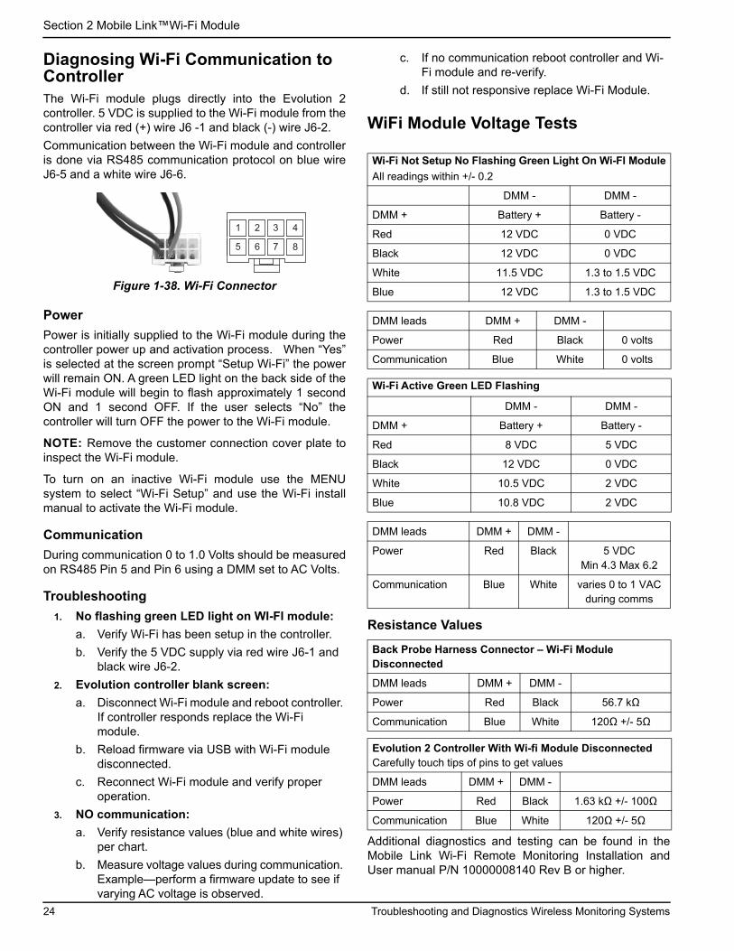
Diagnosing Wi-Fi Communication to ControllerThe Wi-Fi module plugs directly into the Evolution 2controller. 5 VDC is supplied to the Wi-Fi module from thecontroller via red (+) wire J6 -1 and black (-) wire J6-2.
Communication between the Wi-Fi module and controlleris done via RS485 communication protocol on blue wireJ6-5 and a white wire J6-6.
Figure 1-38. Wi-Fi Connector
Power
Power is initially supplied to the Wi-Fi module during thecontroller power up and activation process. When “Yes”is selected at the screen prompt “Setup Wi-Fi” the powerwill remain ON. A green LED light on the back side of theWi-Fi module will begin to flash approximately 1 secondON and 1 second OFF. If the user selects “No” thecontroller will turn OFF the power to the Wi-Fi module.
NOTE: Remove the customer connection cover plate toinspect the Wi-Fi module.
To turn on an inactive Wi-Fi module use the MENUsystem to select “Wi-Fi Setup” and use the Wi-Fi installmanual to activate the Wi-Fi module.
Communication
During communication 0 to 1.0 Volts should be measuredon RS485 Pin 5 and Pin 6 using a DMM set to AC Volts.
Troubleshooting
1. No flashing green LED light on WI-FI module:
a. Verify Wi-Fi has been setup in the controller.
b. Verify the 5 VDC supply via red wire J6-1 and black wire J6-2.
2. Evolution controller blank screen:
a. Disconnect Wi-Fi module and reboot controller. If controller responds replace the Wi-Fi module.
b. Reload firmware via USB with Wi-Fi module disconnected.
c. Reconnect Wi-Fi module and verify proper operation.
3. NO communication:
a. Verify resistance values (blue and white wires) per chart.
b. Measure voltage values during communication. Example—perform a firmware update to see if varying AC voltage is observed.
c. If no communication reboot controller and Wi-Fi module and re-verify.
d. If still not responsive replace Wi-Fi Module.
WiFi Module Voltage Tests
Resistance Values
Additional diagnostics and testing can be found in theMobile Link Wi-Fi Remote Monitoring Installation andUser manual P/N 10000008140 Rev B or higher.
2 3 41
6 875
Wi-Fi Not Setup No Flashing Green Light On Wi-FI Module
All readings within +/- 0.2
DMM - DMM -
DMM + Battery + Battery -
Red 12 VDC 0 VDC
Black 12 VDC 0 VDC
White 11.5 VDC 1.3 to 1.5 VDC
Blue 12 VDC 1.3 to 1.5 VDC
DMM leads DMM + DMM -
Power Red Black 0 volts
Communication Blue White 0 volts
Wi-Fi Active Green LED Flashing
DMM - DMM -
DMM + Battery + Battery -
Red 8 VDC 5 VDC
Black 12 VDC 0 VDC
White 10.5 VDC 2 VDC
Blue 10.8 VDC 2 VDC
DMM leads DMM + DMM -
Power Red Black 5 VDC Min 4.3 Max 6.2
Communication Blue White varies 0 to 1 VAC during comms
Back Probe Harness Connector – Wi-Fi Module Disconnected
DMM leads DMM + DMM -
Power Red Black 56.7 kΩ
Communication Blue White 120Ω +/- 5Ω
Evolution 2 Controller With Wi-fi Module DisconnectedCarefully touch tips of pins to get values
DMM leads DMM + DMM -
Power Red Black 1.63 kΩ +/- 100Ω
Communication Blue White 120Ω +/- 5Ω
24 Troubleshooting and Diagnostics Wireless Monitoring Systems

Section 2 Mobile Link™Wi-Fi Module
Terms and AcronymsThe following is a limited glossary of terms and acronyms that define the technology used with Mobile Link Wi-Fienabled modules and controllers. Understanding these terms is important for proper and successful diagnosis ofconnectivity issues.
Term / Acronym Description
Access Point (AP) A networking hardware device that allows a Wi-Fi device to connect to a wired network. AP mode means the generator Wi-Fi is in broadcasting mode. System is ready to be connected to a home network.
Application (App) A computer program that operates on a mobile device such as a tablet or smart phone. Some apps are free, while others must be purchased. Each mobile device manufacturer operates an “app store” where customers can browse, purchase, and download apps.
Connecting Establishing a wireless communication link between two electronic devices.
Firmware Permanent software embedded in a computerized device; typically used as the operating system. Firmware is read-only (non-editable) and can only be installed or updated by someone with specialized knowledge and system access. Firmware can also be automatically updated via Wi-Fi if connected to the home network.
Hardware The electronics, wires, and devices that form the physical structure of a computer-based system.
Internet Service Provider (ISP) A third-party company supplying customers with the hardware, software, and data plans needed to connect computers and / or mobile devices to the Internet.
Internet Protocol (IP) Address A unique number assigned to any device accessing the Internet. A typical IP address is in the form of a dotted decimal number like: 01.234.567.90.
LAN (Local Area Network) A network of computers and peripheral devices that share a common communication line or file server. LANs can be wired or wireless.
MAC (Media Access Control) address
The unique identifier or hardware address of each device on a computer network. It is also referred to as the physical address and takes the form: xx:xx:xx:xx:xx:xx
Mobile Device A computer, laptop, smart phone, or tablet, frequently used by consumers to access the Internet.
Ping A test signal transmitted to check if a network component, such as a Wi-Fi module, is connected to and communicating with the network.
Quick Response (QR) Code A two-dimensional bar code consisting of small black squares arranged in a square grid on a white background. QR codes contain embedded information about a product or links to websites.They are scanned by optical readers, or cameras on mobile devices.
Radio frequency (RF) The section of the electromagnetic spectrum between 3000 Hz and 300 GHz—typically used for communication or signaling.
RS-485 A standard defining the electrical characteristics of drivers and receivers for use in serial communications systems, including Wi-Fi.
Received Signal Strength Indication(RSSI)
A measurement of how well a device can receive a signal from an access point or router.
Service Set Identifier (SSID) An alphanumeric character string which uniquely identifies a wireless local area network (WLAN). SSID is also referred to as the “Network Name” and can be broadcast or hidden.
Smart Phone A handheld computer primarily intended for use as a cellular phone, but with other features such as Internet browsers, clock/timer, camera, voice recorder, apps, text messaging capability, and e-mail.
Software Computer programs that perform specific tasks on a computer-based system. Software is loaded onto the system and (with certain limitations) can be removed, upgraded, changed, or modified to suit user needs and preferences.
Wi-Fi Channel A given radio frequency spectrum is divided into channels; each centered on a target frequency. The minimum or maximum frequency range occupied by a given channel, such as Wi-Fi, depends upon the frequency width (usually 20Mhz or 40Mhz). Channels One (1), Six (6), or Eleven (11) are recommended for Wi-Fi networks to avoid signal interference caused by channel overlap.
Wireless Fidelity (Wi-Fi®) A type of wireless network technology used for connecting to the Internet. Wi-Fi network frequencies are located at 2.4Ghz or 5Ghz. These frequencies prevent transmission interference with cellphones, broadcast radio, TV antennas, or two-way radios.
Wired Equivalent Privacy (WEP)
An optional authentication and/or encryption mechanism defined in the IEEE 802.11 standard designed to prevent casual network eavesdropping. WEP is considered a weak and compromised legacy form of wireless security.
Troubleshooting and Diagnostics Wireless Monitoring Systems 25

Section 2 Mobile Link™Wi-Fi Module
This page intentionally left blank.
26 Troubleshooting and Diagnostics Wireless Monitoring Systems


Part No. 10000008828 Rev. A 10/04/2018©2018 Generac Power Systems, Inc.All rights reservedSpecifications are subject to change without notice.No reproduction allowed in any form without prior written consent from Generac Power Systems, Inc.
Generac Power Systems, Inc.S45 W29290 Hwy. 59Waukesha, WI 53189
1-888-GENERAC (1-888-436-3722)www.generac.com