Embed Size (px)
Citation preview

TRIKE WING
“Still 17”
MANUAL
Size: ____________
Manufactured by: AEROS Ltd. Tel: (380 44) 455 41 18, Post-Volynskaya St. 5 Fax: (380 44) 455 41 16 Kiev 03061 E-mail: [email protected], UKRAINE http://www.aeros.com.ua
Date of production: ____________________ Serial number: _______________________

1
Table of Contents
Sect ion 1. General Information_____________________________________________________3
1.1. Introduction__________________________________________________________________________3
1.2. Definitions 1.3. Main Data___________________________________________________________________________3
Sect ion 2. Set Up Procedure________________________________________________________4
2.1. Set Up Procedure From The Package 4 Meters Long __________________________________4 2.2. Set Up Procedure From The Package 6 Meters Long __________________________________7
Sect ion 3. Prefl ight Inspection Of The Glider ___________________________________14
3.1. Beginning At The Nose______________________________________________________________14 3.2. Along The Left Leading Edge ________________________________________________________14 3.3. At The Left Wingtip__________________________________________________________________14 3.4. Along The Trailing Edge, Left Wing __________________________________________________14 3.5. From The Rear Keel________________________________________________________________15 3.6. Along The Trailing Edge, Right Wing ________________________________________________15 3.7. At The Right Tip____________________________________________________________________15 3.8. Along The Right Leading Edge ______________________________________________________15 3.9. Under The Wing At The Control Bar _________________________________________________16 3.10. Fit The Nose Cone_________________________________________________________________16
Sect ion 4. Inspection Of The Wing ________________________________________________17
4.1. Sail Check-Up______________________________________________________________________17 4.2. Cable System_______________________________________________________________________17 4.3. Checking The Tubings______________________________________________________________18 4.4. Checking The Battens_______________________________________________________________18 4.5. Fasteners___________________________________________________________________________18
Sect ion 5. Maintenance_____________________________________________________________19
5.1. Wing Tuning_________________________________________________________________________19 5.1.1. Cg Adjustment___________________________________________________________________19 5.1.2. Turn Trim________________________________________________________________________19 5.2. Maintenance________________________________________________________________________20 5.3. Storage_____________________________________________________________________________20 5.4. Transportation______________________________________________________________________20
In Closing – A Few Final Words On Your Safety _______________________________21
Log Book_______________________________________________________________________________22
Schemes_______________________________________________________________________________23

2

3
Section 1. GENERAL INFORMATION 1.1. I N T R O D U C T I O N
Thank you for purchasing an Aeros trike wing.
The Still -17 is a two sitter trike wing with 30 % double surface, designed for the wide range of pilots: from beginners through to the most experienced pilots who want to have fun in powered flying. The design concept of the Still-17 was very simple: it had to be easy to take off and land, easy to fly, easy to pack up and transport. It had to have the minimum possible weight without compromising structural strength. We believe that we have succeeded in all aspects of the Still -17 design. Take off and landing
with the Still -17 is very easy. It is very well coordinated wing with smooth and predictable feedback given to the pilot. Control pressures are light whilst retaining a stable feel. A small percentage double surface with a minimum amount of battens for maintaining the
airfoil has resulted in significant weight reduction and a fast set up time. The structural strength of the Still -17 is sufficient for different flight conditions with defined
wing load. Please read and be sure you thoroughly understand this Manual before flying your Still-17. Be sure you are thoroughly familiar with set up, break down, preflight and maintenance procedures as described in this manual. If you have access to the Internet, please visit us regularly at http://www.aeros.com.ua We wish you a safe and enjoyable flying career. Aeros Ltd.
1.2 Definitions Definitions used in this Manual such as WARNING, CAUTION and NOTE are employed in the following context: WARNING OPERATING PROCEDURES, TECHNIQUES, ETC. WHICH IF NOT FOLLOWED CORRECTLY, MAY RESULT IN PERSONAL INJURY OR DEATH. CAUTION OPERATING PROCEDURES, TECHNIQUES, ETC. WHICH IF NOT STRICTLY OBSERVED, MAY RESULT IN DAMAGE TO THE ULTRALIGHT OR ITS INSTALLED EQUIPMENT NOTE Operating procedures, techniques, etc. which it is considered essential to highlight.

4
1.3. M A I N D A T A Wing type Still Sail area, sqm 17 Wing span, m 10.0 Aspect ratio 5,9 Nose angle, deg 122 Max airspeed, kmph 95 Stall speed, kmph (with max load) 50 Speed of max glide angle, kmph (with max load) 70 Range of operating overloads Ultimate tested strength, G
+4/-2 +6/-3
Total load max, kg 450 Weight without bag, kg 45
WARNING STILL –17 IS NOT DESIGNED TO FLY AT BANK ANGLE OVER 60 DEGREES OR PITCH ANGLE OVER 60 DEGREES OR PITCH ANGLE EXCEEDING 30 DEGREES. OPERATION IN ANY OF THEESE MODES MAY SEVERELY COMPROMISE YOUR SAFETY. WARNING THE FLYING OF ANY TRIKE IN PRESENCE OF TURBULANCE OR GUSTY WIND CAN RESULT IN FLIGHT INVERSION, STRUCTURAL FAILURE OF THE WING AND POSSIBLE FATAL INJURIES. WARNING PERFORMANCE OF THE WINGS WITH TRILAM LEADING EDGE CAN WORSEN IN WET (RAIN, THICK FOG, DEW, ETC.) AND ICE-COVERING CONDITIONS, THEREFORE WE DO NOT RECOMMEND TO FLY THE ULTRALIGHT IN SUCH CONDITIONS, AS THIS CAN COMPROMISE YOUR SAFETY.
Section 2. SET UP PROCEDURE 2.1. SET UP PROCEDURE FROM THE PACKAGE 4 METRES LONG Having used the specific techniques described in this manual you will perform the set up and break down procedures without any difficulties. However, the following procedural descriptions are not intended to be a substitute for the familiarization procedure of your dealer at the time the wing is delivered. The set up procedure should be carried out on a clean, not abrasive surface. Before performing the set up procedure you must place the glider nose to the wind. During this procedure you must make a preflight inspection of the wing. 2.1.1. With the glider in the bag (4 meters long) lay the glider on the ground. 2.1.2. Undo the glider bag zipper. Untie the Velcro straps. Remove the battens, the base tube and the leading edge tubes N3 from the bag. 2.1.3. Turn the glider so that the downtubes packed into the safety bags are on the bottom and the kingpost is on the top.

2.1.4. Unfold the sail along the leading edge (Fig. 1).
a b Fig. 1
2.1.5. There is a self-tapping screw for the turn adjustment at the outer part of the leading edge # 3. The position of the self-tapping screw has been determined and marked after the test flights. Take the screw out before installing the leading edge tube # 3 (Fig. 2).
Fig. 2 Attach the leading edge tubes N3 to the leading edge tubes N2 according to the marking (L-left, R-right, marks should be on top) (Fig. 3).
a
5

b
Fig. 3
4

2.1.6. While installing the leading edge tubes into the sail, place the washout struts facing forward toward the nose of the wing and along the leading edge tubes (Fig. 4). Put washout tips outside of the sail through the washout strut holes. Make sure that the leading edge tube #3 is properly installed.
Fig. 4
2.1.7. Tighten the sail along the leading edge and mount it to the rear leading edge and attach the securing Velcro (Fig. 5). The sail is mounted to the leading edge by the inner (forward) of the two loops of webbing. The outer loop is a pull handle only.
a b Fig. 5
2.1.8. Fix the sail with the self –tapping screw. Make sure you put the screw in the same marked hole it has been removed from (Fig. 6).
5

Fig. 6 2.1.9. Install the keel batten (Fig. 7) and # 1 battens (Fig. 8) in the wing if they are not installed. Aeros convention is that red marked battens go in the left wing and blue marked battens in the right. Battens are numbered from the center outwards, and the longest batten in a Still-17 is designated as the "# 1" batten.
Fig. 7
Fig. 8 2.1.10. Spread the wings all the way. Near the kingpost hole find the shackle of the sweep wires. Pull the shackle out the rear end of the keel pocket, and check that the sweep wires are not wrapped around the keel. Install the pin of the kingpost to the corresponding socket on the keel tube. The kingpost has to be between the sweep wires. Attach the shackle of the sweep wires to the hook on the keel tube.
8

2.1.11. Position the sail mount tang of the nose part of the sail under the nose plate over the bolt and secure the assembly with the self-locking nut (Fig. 9). Screw the self-locking nut full tight and than unscrew it 180 deg. back. Make sure that the sail mount tang moves around the bolt freely. Living a little slack in the joint will provide the leading edge for necessary movement in the bottom nose plate slot.
Fig. 9
2.1.12. Release the sweep wires from the hook on the keel tube to loose a sail tension. 2.1.13. The further set up procedure is similar to the one from a 6-meter long package (Section 2.2, except points 2.2.1-2.2.4).
2.2. SET UP PROCEDURE FROM THE PACKAGE 6 METRES LONG 2.2.1. With the wing in the bag (6 meters long) lay the wing on the ground zipper up (Fig.10).
Fig. 10
2.2.2. Undo the zipper. Remove battens and the base tube from the bag. 2.2.3. Untie the velcro straps. 2.2.4. Turn the glider so that the downtubes packed into the safety bags are on bottom and kingpost is on top (Fig. 11).
9

Fig. 11
Fig. 12 2.2.5. By lifting up and back on the nose batten string push the nose batten fully back into the sail so that the batten tip rest on top of the keel tube (Fig. 13).
2.2.6. Spread the wings so that the sail is a little loose and the glider is resting flat on the ground (Fig. 12).
Fig. 13
2.2.7. Remove the protective bags from the downtubes. Spread the downtubes. Install the base tube according to the marking. Fix the base tube using nuts and safety rings (Fig. 14).
10

Fig. 14
2.2.8. Pull out of the sail the sweep wires and install the pin of the kingpost into the corresponding socket on the keel tube (Fig. 15). NOTE Take care that the reflex wires and the top wires are not wrapped around the keel and are free from the keel hardware. WARNING MAKE SURE THAT THE KINGPOST IS INSTALLED BETWEEN THE SWEEP WIRES (Fig. 13 b)
a b Fig. 15
2.2.9. Attach the hook of the top rear wire with the washout wires to the thimble of the top front wire (Fig. 16). Make sure that the hook is not inverted and the reflex wires or top wires are not twisted.
9

Fig. 16 2.2.10. Remove battens from the batten bag, and check each batten for symmetry against the corresponding batten from the other wing. Align the battens at the nose, and at about the 60% chord point. There should not be any deviation of more than 3 mm (1/8’’) from one batten to the other along the full length of the battens. Correct any asymmetry using the template. NOTE Two longest battens (# 1 battens) are not removed from the battens pockets during the break down procedure. Aeros convention is that red marked battens go in the left wing and blue marked battens in the right. Battens are numbered from the center outwards, and the longest batten on the Still-17 is designated as the "# 1" batten. Install the cambered top surface battens in the sail and fix them with the double tensioned rubber bands. Insert battens carefully, so as to minimize stress and wear on the sail. Never insert or remove top surface battens with the crossbar tensioned (except for up to the last two on each side) and never insert or remove battens with heavy wind pressure on the top of the sail or in any condition which causes the battens to slide with great resistance in the pockets. If you choose not to check your battens for symmetry before each flight, you should, at
minimum check them once a month. Do not install the tip battens at this stage
(Fig. 17) .
Fig.17
7

2.2.11. Check all wires for twisted thimbles or tangs (Fig. 18 ).
a
b Fig. 18 2.2.12. Attach the shackle of the sweep wire to the hook on the keel tube (Fig. 19). WARNING AN IN-FLIGHT DISANGAGEMENT OF THE SWEEP WIRE ATTACMENT WILL CAUSE A COMPLETE LOSS OF STRUCTURAL SUPPORT OF THE GLIDER AND TOTAL LOSS OF CONTROL. NEVER ATTACH THE PULL HANDLE OF THE SHACKLE TO THE HOOK, EVEN TEMPORARILY.
Fig. 19 2.2.13. Install the tip battens and fix them with the double tensioned rubber bands.
12

2.2.14. Put the glider on the A-frame. Secure the nose catch of the bottom wires on the nose junction channel using the clevis pin and the safety ring (Fig. 20).
Fig. 20
Check all wires for twisted thimbles or tangs. 2.2.15. Install the washout tips: swing them to the right place underneath the corresponding top surface battens through the hole in the bottom surface (Fig. 21).
Fig. 21
12

2.2.16. Remove the protective bag from the hang bracket. 2.2.17. Do a complete preflight inspection of the glider, Section 3.
Section 3. PREFLIGHT INSPECTION OF THE GLIDER
Conduct a complete preflight inspection of the glider, checking all assemblies, which have not already been checked. Every bolt, nut, pin, safety ring, and fastener of any kind should be checked during every pre-flight. A full pre-flight inspection should precede every flight you make, not just the first flight of the day. Carefully check the entire length of the leading edge pocket to insure that the mylar insert is lying flat in the pocket. If any section of the mylar is folded under, de-tension the crossbar, remove the batten closest to the area of distortion, and unfold the mylar. 3.1. BEGINNING AT THE NOSE, Check all self-locking nuts, the clevis pin and the safety ring, which secure the lock of the bottom front wires (Fig. 22).
Fig. 22
13

15
3.2. ALONG THE LEFT LEADING EDGE Open the crossbar junction access zipper and look inside, making sure that side wires are properly secured to the crossbar, that the thimbles are not cocked on the tang. Check the splint pin and the nut, which secures the leading edge – crossbar junction. Check that the sail is not caught on the crossbar end, or on any of the hardware. Remember to close the access zipper (Fig.23).
Fig. 23 3.3. AT THE LEFT WINGTIP Look into the sail at the wing tip, and check that the tip batten is properly installed. Check that the washout tip is installed properly. 3.4. ALONG THE TRAILING EDGE, LEFT WING Check that there are no tears in the sail material along the trailing edge. Check that all battens are properly secured. Check that the washout tip is properly secured in position supporting the batten. Check that the bridles are properly engaged. Check the trailing edge for any cuts, tears or broken stitching. Check that lifelines are not twisted or tangled. (Fig. 24).
Fig. 24

3.5. FROM THE REAR KEEL Check that the sweep wires are tight and secured on the hook on the keel tube (Fig. 25).
Fig. 25
Check the kingpost top for proper attachment of the bridles and condition of the top rear wire and bridle wires. Check the keel mount webbing, and bottom rear wires are safely secured to the keel tube.
3.6. ALONG THE TRAILING EDGE, RIGHT WING Same as for the left wing.
3.7. AT THE RIGHT TIP Same as for the left tip. 3.8. ALONG THE RIGHT LEADING EDGE Same as for the left leading edge.
16

3.9. UNDER THE WING AT THE CONTROL BAR Check the cables at the control bar corners, making sure there are no kinks or twisted thimbles. Inspect each Nico press sleeve for slippage and/or corrosion. Check each thimble for distortion, flattening or wear where it touches a bolt, shackle or tang. Check for proper installation of all nuts and safety rings at the control bar corners. Check that the downtubes are straight and undamaged. Check the sweep wires for wear. Check the crossbar center plates assembly including the sweep wires/X-bar junction and the center bolt. Also, visually inspect the crossbars by sighting along the length of the crossbars looking for any evidence of damage.
Check all bolts, nuts and the safety rings, which secure the downtubes to the channel. Make sure that the channel and hang brascet are secured (Fig. 26).
Fig. 26 3.10. FIT THE NOSE CONE Attach the Velcro at the top rear of the nose cone (Fig. 27a). Pull the bottom corners of the nose cone back until the nose cone is tight around the nose and secure the Velcro on the bottom of the nose cone (Fig. 27b). WARNING DO NOT FLY WITHOUT THE NOSECONE.
a b Fig. 27
Now your glider is ready for mounting on the trike.
16

17
Section 4. INSPECTION OF THE WING
The sail should be inspected once every three months or after each 50 flying hours. The frame should be inspected once a year, after every 100 flying hours, and after every hard landing.
4.1. SAIL CHECK-UP 4.1.1. Checking the sail surface and seams. There should be no cuts, ruptures, threadbare holes and torn seams on the sail. Any torn seams should be re-stitched. Cuts and ruptures on the fairing and bottom surface (BS) of the sail that are not longer than 30 mm can be patched up with self-adhesive Dacron. The Dacron must be of a weight of not less than 100 g/m. larger cuts and ruptures are to be repaired by stitching on a reinforcing piece of the same fabric (stitched along the edges). Any rupture shorter than 50 mm can be repaired in this manner, but more complicated repairs and all cuts near the trailing edge should be carried out in the workshop of producing company. If any of the batten tightening cords are torn or heavily worn they must be replaced. 4.1.2. Keep an eye on the sail grommets/eyelets and all areas of the sail that are subject to extra stress, especially the keel section, the nose section of the leading edge and the outer tip section of leading edge.
4.2. CABLE SYSTEM
The cables must be checked for broken wires and corrosion. If any defect on a wire is observed, no matter how small, the cable in question MUST BE REPLACED. It is recommended that the entire cable system be replaced once every four years irrespective of service conditions. A NOTE ABOUT CABLES AND CABLE MAINTENANCE The cables which support the wing’s airframe are critical components of the wing’s structure, and must be maintained in an air worthy condition. It is a general practice in the design of aircraft structures to design to an ultimate strength of 1.5 times the highest expected load in normal service. Still-17 cables, like other structural components on the wing, are typically designed with a structural safety factor of only about 50% above the expected maximum load. No significant loss in cable strength can be tolerated. A cable with even a single broken strand must be replaced before the wing is flown again. A cable which has been bent sharply enough to have taken a permanent set must also be replaced immediately. Some degree of fatigue due to repeated bending of cables is almost unavoidable in an aircraft that is assembled and disassembled with every flight. Bottom side wires are subject to the highest loads in flight, and are therefore the most critical.

18
4.3. CHECKING THE TUBINGS
To check the condition of the wing tubes the sail should be removed from the wing frame and the tubes should be detached at the joints. The tubes are to be inspected visually. When there is suspicion of damage, the points in question should be inspected using a magnifying glass of (5-10) X magnification. There should be no trace of corrosion, cracks, bends or dents. 4.4. CHECKING THE BATTENS
The batten Still-17 should be checked against the template and the bends should be adjusted if necessary. Check all the plastic batten heads and tails and replace if necessary. 4.5. FASTENERS
Check all fasteners (bolts, screws, nuts, splint pins etc.) for corrosion. Any corroded fasteners should be replaced. Bolts should not be worn and/or bent. Key bolts should be checked most thoroughly for cracks between the head and the bolt body. These are the bolts at the control bar side and bottom joints, the sweep wires attach points and the rear cable attachment point on the keel tube. If any cracks are observed - REPLACE IMMEDIATELY!

Section 5. MAINTENANCE
5.1. WING TUNING
- The Still-17 wing should fly straight and level without any pilot input with a cruising speed of between 60 kph and 75 kph.
- Before making any adjustments to the wing, first check that the wing is in the standard condition and that the battens all conform to the Still-17 batten template.
- If the wing is not new, check the condition of the frame especially the outer leading edge tubes. The best is to remove the leading edges and check that they have the same bend in them and when under load they flex equally.
- Do not exceed the adjustment limitations. - Do one adjustment at a time and test fly each time to measure the effect of each
change. - Note all adjustments and changes in the log book. - Only tune and test fly the wing in perfect flying conditions.
5.1.1. CG Adjustment
- Moving the wing hang block forward along the keel tube will speed the wing up. - Moving the wing hang block backwards along the keel tube will slow the wing down.
5.1.2. Turn Trim
2.1.4 There is a self-tapping screw for the turn adjustment at the outer part of the leading edge # 3 (Fig. 28). By adjusting a wingtip down, the lift on the end of that wing will be increased and that will lift that wing in flight. Adjust the self-tapping screw up by 2.5 mm at a time. By adjusting the wingtip up, the lift will be decreased on that side and the wing will drop on that side. Adjust the self-taping screw down by 2.5 mm at a time.
Adjust one wingtip at a time and test fly after each adjustment.
Fig. 28
19

21
5.2. MAINTENANCE
- With correct maintenance your wing will retain its good condition for many years. - We recommend that you do not expose your wing to any more direct sunlight than
necessary. Do not leave it standing in the sun for long periods of time when you are not flying it.
- Do not leave your wing on the trike for a long period of time when the wind is strong. It will decrease the life of the sail; hang junction and frame of your wing.
- Your wing should be dried thoroughly after being exposed to rain or any other source of moisture.
- Your sail should never be washed with anything other then fresh water, as any soap or detergent will most likely degrade the cloth and may adversely affect the flight characteristics of your wing.
- If your wing is ever exposed to salt water you will need to have the wing completely disassembled in accordance with the recommended annual inspection procedure. All frame parts will need to be disassembled, including the removal of all sleeves and bushings, flushed liberally with fresh water, dried completely.
- When you set up or break down your wing, take care not to allow sand, soil and dirt to
enter the sail, batten pockets or tubes. Keep the leading edge tube telescopic connectors thoroughly clean as set up or break down will become difficult or impossible if they are dirty. Swab the tubes with a rag.
- Keep all the wing’s foam padding that was originally supplied and use in the same places when re-packing the wing.
5.3. STORAGE
- You must store the wing in its bag in a dry place on soft bedding. Before storage you must ensure that the sail is dry.
- The frame of the wing must not be subjected to load during storage and the tubes must not be bent under their own weight.
- The wing can be storage in temperatures ranging from -10°C to +25°C. 5.4. TRANSPORTATION
- The wing may be transported in its bag in any vehicle that offers protection from
mechanical damage, soiling and long exposure to rain. It is not recommended that the wing be carried or transported without its bag.

22
IN CLOSING - A FEW FINAL WORDS ON YOUR SAFETY
- UL flying is an active air sport with associated risks. Your safety can be greatly
enhanced by following a few simple rules:
- Your wing is delivered to you ready to fly. Do not make any adjustments, which are not described in this manual.
- If you are in doubt about any aspect of your wing you should consult your dealer or
Aeros for advice.
- Only fly after having attended a good school.
- Fly a wing suited to your level of ability. A new risk may arise when you first fly a new type of the wing.
- The reactions of your new wing may well differ from those of the wing you where used
to. In order to keep this risk low, we recommend that you gradually become familiar with your new wing.
- Before every take-off always do both an assembly check and a pre-flight check.
- Do not take off if the sail is wet, especially the leading edge, as the stall speed will
increase significantly.
- Always fly with a dry sail!
- Take special care to avoid ice covering the glider, particularly the leading edge in wintertime.
- A wet wing must be dried before storing. Do not leave your glider wet for more than one
day, because corrosion may result.
- Never fly alone.
- Don’t push your luck. It is your responsibility to know the limits of your wing and the limits of your own experience. Remember, that ultimately your safety is your responsibility.
- Fly only in places, which are suitable for flying.
- With proper care and maintenance, your wing will retain a high level of airworthiness for
many years.
Have fun. Fly safely. Aeros Team

23
LOG BOOK
TABLE OF FLIGHT HOURS
DATE NUMBER OF FLIGHT TOTAL HOURS BY WHOM


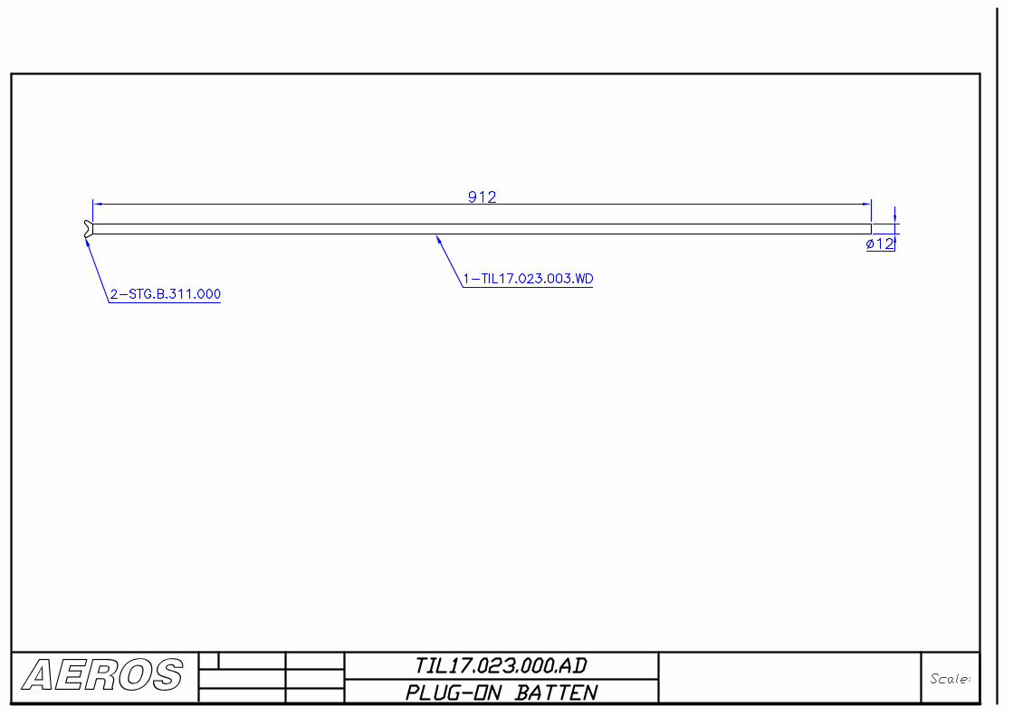


AEROSPRF15.193.000.AD
CONTROL BARby:
Zakidyshev 16.07.03
Date: Scale:
180320
1-PRF15.190.003.WD
4-PRF15.290.000.AD
3-PRF15.191.000
2-PRF15.193.005.WD

AEROSPRF15.200.000.AD
KING POSTScale:
1150
3-PRF15.202.000 2-PRF15.201.000
1-PRF15.200.003.WD
5-PRF15.204.000
6-BLIND RIVET 34000 4X126-BLIND RIVET 34000 4X12
10 10
4-PRF15.203.000