Embed Size (px)
Citation preview
Ref: CG-WI-4.2.1-1 Ver1.0
Page 1 of 48 Date of issue: January 2018
Spec. No. RDSO/CG-18001
Signature
Name & Designation
Prepared By
Checked By
Approved By
INDIAN RAILWAYS
TRIAL SPECIFICATION
SCHEDULE OF TECHNICAL REQUIREMENT FOR
SUPPLY, INSTALLATION, COMMISSIONING & MAINTENANCE OF GPS LOCATION BASED PUBLIC ADDRESS & PASSENGER
INFORMATION SYSTEM AND LED DESTINATION BOARDS IN LHB TYPE AC AND NON- AC COACHES
S.No. Month/Year
of issue Revision /
Amendment Page No.
Reason for Amendment
1. January 2018 Nil N A First Issue
Issued By: Carriage Directorate
Research Designs and Standards Organization Manak Nagar, Lucknow - 226011.
Ref: CG-WI-4.2.1-1 Ver1.0
Page 2 of 48 Date of issue: January 2018
Spec. No. RDSO/CG-18001
Signature
Name & Designation
Man Singh Meena JE/D/Carriage Prepared By
Ajay Kumar Srivastava SSE/Carriage Checked By
Vivek Acharya/ Director Carriage/E&S and Brake
Approved By
INDEX
Clause No.
DESERIPTION Page No.
PART-I: GENERAL
1 Introduction 04
2 Definition & Explanation 05
3 Scope of Supply 06
4 Eligibility Criterion 08
5 Prototype Approval 08
6 Comprehensive Annual Maintenance 08
7 Supplier‟s Responsibility 09
8 Spare Parts, Reserve Apparatus 09
9 Cost 10
10 Warranty 10
11 After Sales Service 10
12 Training 10
13 Packing 11
14 Marking 11
PART-II: FUNCTIONAL & DESIGN REQUIREMENT
14 Functional Requirements 12
15 System Level Block Diagram 13
16 Design Requirements 14
17 Description of Equipment‟s 28
18 Communication Protocol 34
19 Data Base 34
20 Inspection & Tests by Manufacturer/Supplier 35
21 Batch Testing of LEDs. 35

Ref: CG-WI-4.2.1-1 Ver1.0
Page 3 of 48 Date of issue: January 2018
Spec. No. RDSO/CG-18001
Signature
Name & Designation
Man Singh Meena JE/D/Carriage Prepared By
Ajay Kumar Srivastava SSE/Carriage Checked By
Vivek Acharya/ Director Carriage/E&S and Brake
Approved By
22 Routine tests 36
23 Inspection of Finished Products by Inspecting Authority.
37
Part-III. Infrastructure Requirement
1. Scope 39
2. Requirements 39
3. Manufacturing Facilities 39
4. Testing facilities 40
5. Quality Control Requirements 40
6. Documentation 41
7. Training 41
Annexures
Annexure No. Description
Annexure-1/A to 1/C Drawings for Power Supply Connections 42 to 44
Annexure-2 Location for Fixing/Mounting of LED Destination Board 45
Annexure-3 Parameters to be checked during field Trial. 46
Annexure-4 Undertaking Against Cartel Formation 47
Annexure-5 Details of public address system 48

Ref: CG-WI-4.2.1-1 Ver1.0
Page 4 of 48 Date of issue: January 2018
Spec. No. RDSO/CG-18001
Signature
Name & Designation
Man Singh Meena JE/D/Carriage Prepared By
Ajay Kumar Srivastava SSE/Carriage Checked By
Vivek Acharya/ Director Carriage/E&S and Brake
Approved By
SCHEDULE OF TECHNICAL REQUIREMENTFOR SUPPLY, INSTALLATION, COMMISSIONING & MAINTENANCE OF GPS BASED
PUBLIC ADDRESS & PASSENGER INFORMATION SYSTEM (PAPIS) & LED DESTINATION BOARDS IN LHB TYPE AC AND NON- AC COACHES
Foreword:
0.1 This specification covers the general requirement of design, development construction, pre-wiring, performance, testing, supply, commissioning and after sales service of GPS (Global Positioning System) based Public Address System (PAS), Passenger Information System (PIS) &LED Destination boards for LHB type AC and Non AC coaches including LHB Pantry car & LHB Power car. This specification covers the technical requirements/provision related to material/ tests and does not include all the necessary provisions of contract.
0.2 This schedule draws reference of some specifications & drawings. The latest versions of the relevant specifications shall be taken as reference.
0.3 This specification requires the reference to the following specifications:
Specification Description
IEC 60571 The Safety and reliability requirement of electronic signaling equipment.
EN 50155 International standard covering electronic equipment used on rolling stock for railway applications.
0.4 SCOPE:
This trial specification for “GPS BASED PUBLIC ADDRESS & PASSENGER INFORMATION SYSTEM (PAPIS) & LED DESTINATION BOARDS IN LHB TYPE AC AND NON- AC COACHES” covers three parts. Part-I covers general requirements regarding supply, installation, commissioning and after sales service while Part-II covers the functional & Design requirements and method of quality control of the system. Part –III covers the Minimum M&P and Test Equipment‟s for the manufacturing and testing of the system.
PART-I: GENERAL REQUIREMENTS
1. INTRODUCTION:
This trial specification for GPS BASED PUBLIC ADDRESS & PASSENGER INFORMATION SYSTEM (PAPIS) & LED DESTINATION BOARDS IN LHB TYPE AC AND NON- AC COACHES is prepared to develop a suitable workable system which shall take care for inclusion of future up gradation/additional features. In first phase Passenger address system along

Ref: CG-WI-4.2.1-1 Ver1.0
Page 5 of 48 Date of issue: January 2018
Spec. No. RDSO/CG-18001
Signature
Name & Designation
Man Singh Meena JE/D/Carriage Prepared By
Ajay Kumar Srivastava SSE/Carriage Checked By
Vivek Acharya/ Director Carriage/E&S and Brake
Approved By
with passenger information system and LED destination board shall be integrated for providing all important information in audio and visual form to the passengers. The system should equipped with GPS technology for activating location based audio visual information and features of the system like speed, locations of the coach and calculating kilometer run by the coach on per day/month/year basis. This specification covers the general, functional design requirements of such system for Indian Railway coaches. System should support Key feature and technology based on internet services through Quad Band GSM/GPRS or HSDPA/HSUPA modem or through Wi-Fi connectivity to the base station for remote accessibility of the system and monitoring of important parameters..
2. DEFINITION & EXPLANATION:
2.1. GPS BASED PUBLIC ADDRESS & PASSENGER INFORMATION SYSTEM (PAPIS) & LED DESTINATION BOARDS IN LHB TYPE AC AND NON- AC COACHES means "complete system including all related equipment‟s, such as, main processing unit (MPU), GSM/3G/4G modem, GPS system, LED display unit and LCD display units for outside and inside of the coach,IP65 enclosure for exposed system, suitable power supply, network switches, audio amplifier unit and all associated sub systems and accessories, wires, fittings etc to make system fully functional.
2.2. Following terms are used in specification for their relevant meaning like µP- microprocessor, LCD display unit LED/LCD display unit, LED display unit light emitting diode matrix display unit, GPS- global positioning system, GPRS- General Packet Radio Service, and CPU -central processing unit.
2.3. BMU - Base monitoring unit, MPU- main processing unit, PAS- passenger address system and PIS -Passenger information system.
2.4. `Supplier' means the firm/company on whom the order for the manufacture, supply, installation and commissioning and maintenance of the GPS based Public Address & Passenger Information System (PAPIS) & LED Destination Boards in LHB type AC and Non- AC coaches are placed or will be placed.
2.5. „PURCHASER‟ means the Indian Railways on behalf of the President of the Republic of India, who is purchasing the system.
2.6. „INSPECTING AUTHORITY’ means the Organization or its representative nominated by the Purchaser to inspect the system on his behalf.
2.7. RDSO means Research Designs and Standards Organization, Manak Nagar, Lucknow-226011.
2.8. Indian Railways is hereafter referred to as IR.

Ref: CG-WI-4.2.1-1 Ver1.0
Page 6 of 48 Date of issue: January 2018
Spec. No. RDSO/CG-18001
Signature
Name & Designation
Man Singh Meena JE/D/Carriage Prepared By
Ajay Kumar Srivastava SSE/Carriage Checked By
Vivek Acharya/ Director Carriage/E&S and Brake
Approved By
2.9. In case of any clarification in respect of any clause of this specification or drawings, the same shall be obtained from purchaser/ DG(Carriage),RDSO.
3. SCOPEOFSUPPLY:
3.1. The scope of supply includes the following systems and sub systems: Coach Wise requirement along with networking devices, connectors, wiring for communication & power supply. Tentative wiring scheme for Power supply is attached at Annexure 1A to 1C.
Sl Description of unit Quantity per coach
Type of coach
LHB AC coaches
LHB Non-AC
(Reserved) coaches
LHB Non-AC (Un-
Reserved) coaches)
1 Slave PIS LCD Display unit
Description of Slave Destination Board
Display system shall be as per clause no.
17.4 of Part –II of this specification.
AC2T AC3T
02 Nil Nil
AC Ist
01 in each coupe
Chair Car 04
2 Slave PIS LED Display unit
Description of Slave LED Display Unit
shall be as per clause no. 17.3 of Part –II
of this specification.
LHB Sleeper and Chair car
Nil
02 -
GS & Pantry car
- 02
Power Car
- 01
3 Main Processing Unit (MPU)
Description of Main Processing Unit shall
be as per clause no. 17.1 of Part –II of
this specification.
01 per coach
4 Slave Destination Board Display unit:
Description of Slave Destination Board
Display system shall be as per clause no.
17.2 of Part –II of this specification.
02 unit per coach
5 Boxed enclosure Power Supply unit
Description of Boxed enclosure Power
Supply unit shall be as per clause no.
01unit per coach
Ref: CG-WI-4.2.1-1 Ver1.0
Page 7 of 48 Date of issue: January 2018
Spec. No. RDSO/CG-18001
Signature
Name & Designation
Man Singh Meena JE/D/Carriage Prepared By
Ajay Kumar Srivastava SSE/Carriage Checked By
Vivek Acharya/ Director Carriage/E&S and Brake
Approved By
17.5 of Part –II of this specification.
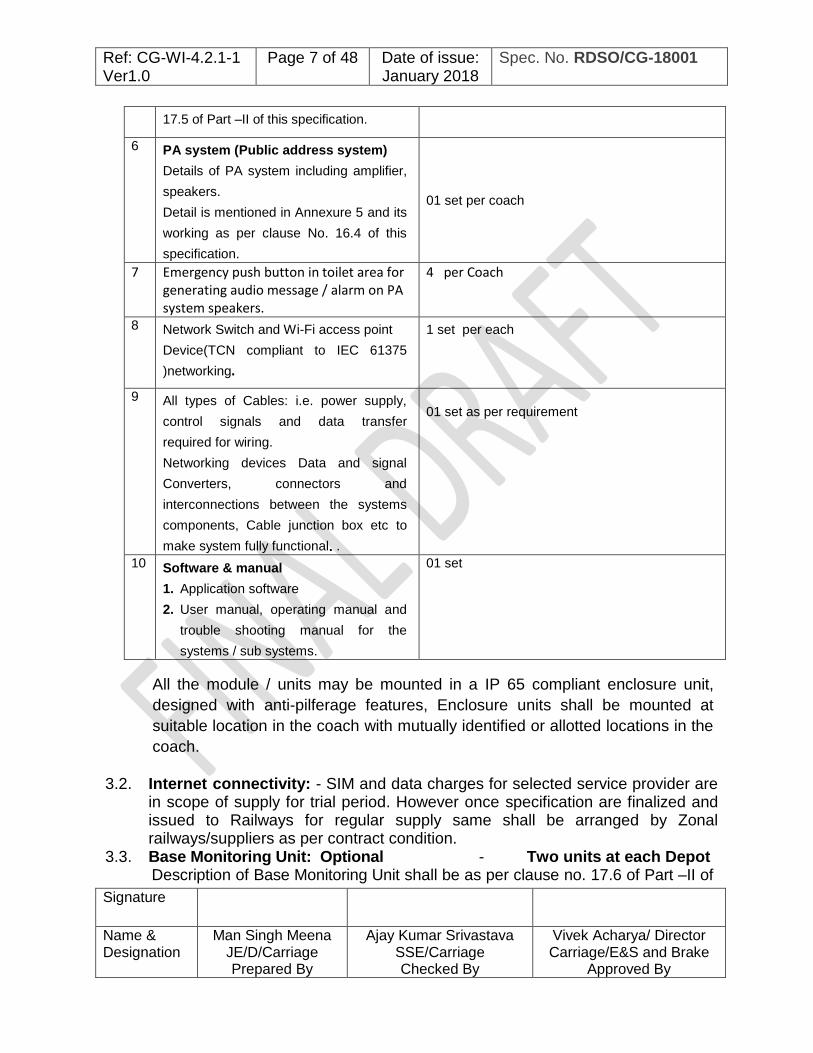
6 PA system (Public address system)
Details of PA system including amplifier,
speakers.
Detail is mentioned in Annexure 5 and its
working as per clause No. 16.4 of this
specification.
01 set per coach
7 Emergency push button in toilet area for generating audio message / alarm on PA system speakers.
4 per Coach
8 Network Switch and Wi-Fi access point
Device(TCN compliant to IEC 61375
)networking.
1 set per each
9 All types of Cables: i.e. power supply,
control signals and data transfer
required for wiring.
Networking devices Data and signal
Converters, connectors and
interconnections between the systems
components, Cable junction box etc to
make system fully functional. .
01 set as per requirement
10 Software & manual
1. Application software
2. User manual, operating manual and
trouble shooting manual for the
systems / sub systems.
01 set
All the module / units may be mounted in a IP 65 compliant enclosure unit,
designed with anti-pilferage features, Enclosure units shall be mounted at
suitable location in the coach with mutually identified or allotted locations in the
coach.
3.2. Internet connectivity: - SIM and data charges for selected service provider are
in scope of supply for trial period. However once specification are finalized and issued to Railways for regular supply same shall be arranged by Zonal railways/suppliers as per contract condition.
3.3. Base Monitoring Unit: Optional - Two units at each Depot Description of Base Monitoring Unit shall be as per clause no. 17.6 of Part –II of

Ref: CG-WI-4.2.1-1 Ver1.0
Page 8 of 48 Date of issue: January 2018
Spec. No. RDSO/CG-18001
Signature
Name & Designation
Man Singh Meena JE/D/Carriage Prepared By
Ajay Kumar Srivastava SSE/Carriage Checked By
Vivek Acharya/ Director Carriage/E&S and Brake
Approved By
this specification.
3.4. Centralized Web Server (not in the scope of supply): For hosting of online services and database of all the train routes, rake
formations of trains a web server (server availability 100 % uptime round the clock) shall be hired by Indian Railway to serve the entire fleet of coaches as well as prospectus users of the system.
3.5. The purchaser can purchase any or all of the above sub systems based on their requirements.
3.6. The scope of the supply includes acceptance testing, installation and commissioning of the complete system on the coaches, On-Site Replacement Warranty.
4. ELIGIBILITY CRITERIA:
4.1 Firm /manufacturer shall have adequate experience of design, development
and manufacturing of similar system like onboard vehicle tracking, monitoring of assets, passenger information display boards or online management of data interchange between control center system and onboard system in rolling stock (rail) application and shall be capable of developing material to the required quality and standards.
4.2 Firm/manufacturer should have installed successfully at least 100 such systems in Railways in past and have completed minimum two years satisfactory service. The list of supplies made along with contact details of the customers and performance certificate should be submitted as documentary evidence.
5. PROTOTYPE APPROVAL AND FIELD TRIAL PERFORMANCE
MONITORING: 5.1 The prototype approval by RDSO shall be mandatory followed by field trial
performance monitoring of the system offered on two Railways advised by RDSO. Parameters for the performance field trial are specified at Annexure ‘3’.
5.2 For field trial performance monitoring of the system, Firms covered under clause 4.2 shall initially supply 50 coach sets to the 2 specified railway for exclusive field trial of 06 months period as per detail trial scheme finalized after prototype approval.
6. COMPREHENSIVE ANNUAL MAINTENANCE CONTRACT: The supplier shall be liable for Comprehensive Annual Maintenance Contract as per Para 3.4 of this section. Comprehensive annual maintenance shall be required for maintaining the system. The Comprehensive annual maintenance shall include

Ref: CG-WI-4.2.1-1 Ver1.0
Page 9 of 48 Date of issue: January 2018
Spec. No. RDSO/CG-18001
Signature
Name & Designation
Man Singh Meena JE/D/Carriage Prepared By
Ajay Kumar Srivastava SSE/Carriage Checked By
Vivek Acharya/ Director Carriage/E&S and Brake
Approved By
the following items:
A) Quarterly Maintenance: a. Checking the entire system for its:
Working reliability. Mechanical fixing thoroughly.
b. Checking the entire system for water-tight sealing arrangement and any visual defect.
c. Monitoring the power supply, voltage, and wiring etc. periodically.
d. Monitoring the antenna connectors.
B) Break down Maintenance
Concerned Railway /Coaching Depot shall inform the supplier regarding failure/malfunction of any equipment of PAPIS system. After receipt of information, firm should attend the failure not later than 03 days.
Note:
1. The AMC shall also cover the updating of route data/customized messages in all coach units installed as per latest time table of I.R. as and when required by the purchaser. After updating route data a soft copy of updated route data shall be provided to the purchaser .And rectification of defect occurred during service.
2. Supp l ie r shall also update/change latest version of the applicable system software as and when required by the purchaser.
3. For checking / fixing of the DISPLAYBOARDS & MPU or Power supply Unit , Railway authorities shall provide necessary assistance to supplier and ensure that the checking is carried out under safe conditions.
7. SUPPLIER’S RESPONSIBILITY
The Supplier shall be responsible for the execution of the contract strictly in accordance with the terms and the conditions of this specification and the conditions of contract made with purchaser.
8. SPARE PARTS, RESERVE APPARATUS. 8.1 Necessary spares to be supplied with each set of equipment. List of spares for
day-to-day maintenance and for POH in the form of periodic overhaul kit. 8.2 Availability of Sufficient spares for the system to be ensured by the firm for ease
of maintenance during failure for a period of five years after expiry of warranty.

Ref: CG-WI-4.2.1-1 Ver1.0
Page 10 of 48
Date of issue: January 2018
Spec. No. RDSO/CG-18001
Signature
Name & Designation
Man Singh Meena JE/D/Carriage Prepared By
Ajay Kumar Srivastava SSE/Carriage Checked By
Vivek Acharya/ Director Carriage/E&S and Brake
Approved By
9. COST
The Purchaser reserves the right to either buy the complete system as offered or any part thereof based on items wise break-up of cost indicated by the Supplier.
10. Warranty and (Annual Maintenance Contract) AMC On-Site Replacement Warranty for 24 months from date of fitment or 30 months from date of receipt and commitment to undertake Comprehensive Annual Maintenance Contract after warranty period for 60 months and should be extendable further as per requirement. For extension of AMC it is to be initiated well before expiring existing AMC.
11. AFTER SALES SERVICE
11.1 Installation, commissioning, and proper functionality in AMC/warranty period is responsibility of supplier..
11.2 Supplier shall associate with Indian Railways during the trials of system. He shall also undertake to modify the equipment supplied, if required as a result of trials.
11.3 The Supplier shall provide one hard & soft copies of the Operation, testing & Maintenance Manuals and servicing Instructions and wall chart to purchaser free of cost at every five set.
11.4 Identification code numbers for main equipment and their component parts to avoid mixing of different applications by mistake.
11.5 In case of any modification, the maintenance instruction/manuals to be revised accordingly and provided to concerning Railways.
12. TRAINING
The Supplier shall undertake to train the following Indian Railway personnel free of cost.
12.1 Railway Technicians Minimum 4 persons per depot for 6 working days training shall be trained on site / in depot to cover maintenance and testing of the complete system.
12.2 Officers and Engineers One officer and 2 Engineers shall be trained at the works of the principles for a minimum period of one week. This training shall cover all the aspects of the complete system like design, manufacture, quality control, maintenance and

Ref: CG-WI-4.2.1-1 Ver1.0
Page 11 of 48
Date of issue: January 2018
Spec. No. RDSO/CG-18001
Signature
Name & Designation
Man Singh Meena JE/D/Carriage Prepared By
Ajay Kumar Srivastava SSE/Carriage Checked By
Vivek Acharya/ Director Carriage/E&S and Brake
Approved By
testing etc.
13. PACKING 13.1 Supplier shall ensure that all outer and exposed portions of the various items of
the system being supplied are covered with suitable protection/packing material to prevent ingress of foreign matter/damage during handling, storage, transportation and stone throwing on it etc.
14. MARKING 14.1 All the individual units shall be provided with a suitable name plate / electrical
rating plate on the enclosure units. The following information shall be available either by etching process or by engraving or screen-printed.
14.2 The name/identification plates shall be of bright anodized aluminum with black letters embossed or etched on white background. These plates shall be fitted by riveting. The nameplate shall indicate the following usual information.
14.3 The following information shall be clearly marked on above mentioned marking plate at a suitable place on each equipment:
i) Name and Address of the manufacturer. ii) Month and Year of the manufacturing. iii) Serial number of Equipment iv) Specification number v) Software and hardware version vi) Schematic diagram of the equipment on the side of the cover.
14.4 The first two digits shall indicate the year of manufacturing and next two digits
shall indicate month. Further next five digits shall indicate manufacturing serial number.
****************

Ref: CG-WI-4.2.1-1 Ver1.0
Page 12 of 48
Date of issue: January 2018
Spec. No. RDSO/CG-18001
Signature
Name & Designation
Man Singh Meena JE/D/Carriage Prepared By
Ajay Kumar Srivastava SSE/Carriage Checked By
Vivek Acharya/ Director Carriage/E&S and Brake
Approved By
PART II: FUNCTIONAL & DESIGN REQUIREMENTS
15. FUNCTIONAL REQUIREMENTS: 15.1 Ambient conditions:
The display unit shall perform satisfactorily under the following climatic conditions
i) Ambient temperature : -5oC to 55oC
ii) Max. Sunlight temperature : 700C
ii) Altitude : Sea level to 2500 m
iv) Relative humidity : 40% to 90% (non condensing)
v) The rainfall is fairly heavy.
vi) During dry weather, the atmosphere is likely to be full of dirt & dust.
vii) Temperature variation may be quite high in the same journey or short period of time.
viii) Coaches operate in coastal areas with continued exposure to salt laden air.
ix) Airborne contaminants like smoke and chemical vapors.
x) Conducting particles like metal clips and filings.
xi) Accidental short circuit by dropped tools, fasteners etc.
xii) Stones may be thrown on the system by the ant-social elements during procession or strikes etc.
xiii) Abrasion damage
xiv) Vibration and shock
15.2 Maintenance Conditions: The coach exteriors are cleaned with mild acidic cleaning agents using brushes with nonmetallic bristles or automatic car washing plants. The system should not be affected by this cleaning either in performance, reliability or aesthetic.
15.3 Power Supply Availability 110V ± 30% AC or DC supply is available from coach circuits. This Supply varies from 77V DC to 138 V DC with 2% ripple.
15.4 Car-body dynamics: ±100 mm vertically ±55 mm laterally ±10 mm longitudinally ±4 degree bogie rotation about center pivot
Ref: CG-WI-4.2.1-1 Ver1.0
Page 13 of 48
Date of issue: January 2018
Spec. No. RDSO/CG-18001
Signature
Name & Designation
Man Singh Meena JE/D/Carriage Prepared By
Ajay Kumar Srivastava SSE/Carriage Checked By
Vivek Acharya/ Director Carriage/E&S and Brake
Approved By
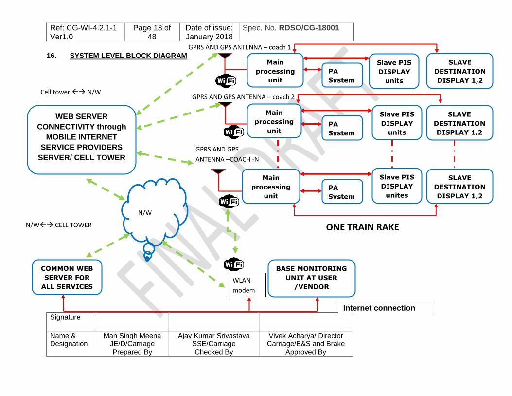
16. SYSTEM LEVEL BLOCK DIAGRAM
WEB SERVER
CONNECTIVITY through
MOBILE INTERNET
SERVICE PROVIDERS
SERVER/ CELL TOWER
N/W
N/W CELL TOWER
Cell tower N/W
Slave PIS
DISPLAY
units
SLAVE
DESTINATION
DISPLAY 1,2
11111
Main
processing
unit
Slave PIS
DISPLAY
units
SLAVE
DESTINATION
DISPLAY 1,2
Slave PIS
DISPLAY
unites
SLAVE
DESTINATION
DISPLAY 1,2
Main
processing
unit
ONE TRAIN RAKE
BASE MONITORING
UNIT AT USER
/VENDOR
COMMON WEB
SERVER FOR
ALL SERVICES
OFFERED
GPRS AND GPS ANTENNA – coach 1
GPRS AND GPS ANTENNA – coach 2
GPRS AND GPS
ANTENNA –COACH -N
WLAN
modem
Internet connection
PA
System
PA
System
PA
System
Main
processing
unit
Ref: CG-WI-4.2.1-1 Ver1.0
Page 14 of 48
Date of issue: January 2018
Spec. No. RDSO/CG-18001
Signature
Name & Designation
Man Singh Meena JE/D/Carriage Prepared By
Ajay Kumar Srivastava SSE/Carriage Checked By
Vivek Acharya/ Director Carriage/E&S and Brake
Approved By
17. DESIGN REQUIREMENTS: The “GPS BASED PUBLIC ADDRESS & PASSENGER INFORMATION SYSTEM (PAPIS) & LED DESTINATION BOARDS IN LHB TYPE AC AND NON- AC COACHES”, including all sub-systems and equipment shall be of proven design for rolling stock application. Entire system can be understood by “SYSTEM LEVEL BLOCK DIAGRAM” as shown above which elaborates the system working / requirements.
17.1 MAIN PROCESSING UNIT (MPU) shall have following features:
17.1.1 Main Processing Unit should be compact fanless industrial grade PC with IP65 compliant enclosure unit along with panel mounted IP 65 compliant external touch screen display and comply the requirements as specified in EN50155 (Railway Application) or IEC 60571. Main processing unit shall have built in GSM/3G/4G modem, GPS receiver, Audio, LAN and Wi-Fi module along with suitable system software (Windows embedded standard / Linux embedded). Detailed system configuration of the system as mentioned in clause no. 17.1.
17.1.2 The Main Processing unit shall support the all the sub systems fitted or to be integrated through networking devices in future. Data /database files shall be transferred to sub systems by standard file transfer /copying / synchronizing techniques i.e. FTP, SMTP or any other suitable method.
17.1.3 LCD/LED Display Units for inside and outside of the coaches shall operate as slave units and consist of LED Matrix Display cards along with LED driver Circuitry and a microprocessor based Control Module for communication with MPU &controlling the LED Display Cards.
17.1.4 The MPU shall be capable of addressing communication with at least 06 LED/LCD display units connected over Cat 6 Ethernet cable & it shall be possible to add at least 04 more display units in future.
17.1.5 Each slave LED/LCD Display unit shall have a Unique Hardware identification number stored within slave unit. Unique HW ID of the LED DISPLAY UNIT shall be a 12-digit code where first three digits shall be vendor code followed by 4 digit of year and month of manufacture (yy/mm format) and the other 5 digits shall be unique serial number assigned by vendor. Vendor code will be assigned after validation of vendor request by RDSO.
17.1.6 Each Main Processing unit shall be identified digitally with an alphanumeric character (up to 12 characters) of the coach number like, "SC00245", "NCR00245" or ECOR00245. Where first two/three/four digits are Zonal Railway

Ref: CG-WI-4.2.1-1 Ver1.0
Page 15 of 48
Date of issue: January 2018
Spec. No. RDSO/CG-18001
Signature
Name & Designation
Man Singh Meena JE/D/Carriage Prepared By
Ajay Kumar Srivastava SSE/Carriage Checked By
Vivek Acharya/ Director Carriage/E&S and Brake
Approved By
Code, next two digits are year of manufacture and the next three digits are running serial number of the coach and last three digits are for optional information as displayed on the coaches. Using this digital identification it can be ensured that only the targeted set of coaches or rake receives the command while programming through BMU / Central web server. The Main Processing unit (MPU) shall also have Hardware ID code similar to LED display units in the embedded memory which can be retrieved by the user at any point of time through the BMU or Central server. The MPU should have a hardcoded identifier that cannot be altered through software means.
17.1.7 The MPU of each coach shall be pre-programmed for the desired train routes in Hindi, English and two Regional languages (originating and terminating stations state languages) for the desired halts/ locations / scheduled stoppage stations along with GPS coordinates and relevant voice segments for PAS, PIS and LED display units using application software provided for this purpose in BMU / web server. This system shall have capability to store and handle the data base of at least 100 up and 100 down train routes with up to 4 language support and capability to display all regional languages in Unicode Bold font (True type fonts for Indian languages available at web site http://www.ildc.in/shall be used by all manufacturers). The display data along with voice data stored in the MPU can be replaced to any required new train data by transferring fresh data from the BMU /Central server; (the old version of a route or least used route data is overwritten automatically in such a case)..
17.1.8 The GSM module of MPU shall be provided with a valid SIM card and a data plan with national data roaming providing pan-India connectivity. The MPU shall remain connected with the BMU/ Web server over GSM/GPRS service or secured Wi-Fi connectivity. Connectivity status of the MPU will be updated to the BMU / Web Server. The vendor shall provide necessary application Program interface on the MPU to allow effective communication with BMU/ Web server.
17.1.9 In case connectivity to MPU is not available the service requests shall be queued in BMU/ Web Server for updating, whenever connectivity is available to the MPU, it shall be updated automatically. It shall be possible for a remote user on an internet enabled PC (BMU) to view the state of a configuration service request and whether the same has been acknowledged or not, through web server acknowledgment state.
17.1.10 When the train passes through programmed train route, GPS receiver receives co-ordinates information of the current location from the GPS satellites. After 15 minutes of arrival at the destination station, the MPU shall automatically reset the selected train number and automatically select return
Ref: CG-WI-4.2.1-1 Ver1.0
Page 16 of 48
Date of issue: January 2018
Spec. No. RDSO/CG-18001
Signature
Name & Designation
Man Singh Meena JE/D/Carriage Prepared By
Ajay Kumar Srivastava SSE/Carriage Checked By
Vivek Acharya/ Director Carriage/E&S and Brake
Approved By
train number route / follow-up route which is already queued in MPU or synchronise (select / download) the follow-up route already selected at server side.
17.1.11 Train route selection on Main Processing Unit shall be done using BMU/ web server interface normally; in case of failure of this mode due non-availability of internet connectivity, authenticated touch screen interface (level 1 or level 2) available in the system shall be used for selection of train route. GUI based application software of the MPU shall be designed such a way, so that selection of the desired route database can be done manually from the available database.
Access Level 1: For route selection, selection of up and down menu etc by AC mechanic.
Access Level 2: For servicing functions like testing of GPS device, communication links, display of route data, management of system passwords, coach number modification addition / deletion / updation of train route information using a USB pen-drive etc by maintenance supervisor.
17.1.12 It shall be ensured that Main Processing Unit (MPU) shall have sufficient security features so that unauthorized access cannot be done. Software/ Data required for functioning of system shall be updated from authorized network/source only.
17.1.13 All the changes made in system software and Data by such access shall be logged within system and shall be synchronized to the BMU/Web server for acknowledgement purpose so that it can be ensured that system has not been accessed by un-authorized means.
17.1.14 Main processing unit should be designed such a way, so that it can work satisfactorily on occurrence of following situation without any attention required.
i. Sudden power off/ sudden failure of power source. ii. Failure of connectivity i.e. GSM/GPRS and WI-FI. iii. Forced / frequent shut down. iv. File system errors and automatic recovery. In all such situation system should be capable to automatically recover / ready for normal operation without any manual attention.
17.1.15 When the Main Processing unit is changed/ replaced from one coach to the other coach, It shall be possible to modify the coach-id stored in the MPU either through the GSM interface (online mode) or manually by touch screen interface provided in MPU, However such modification shall be authenticated password protected. Once updating is done, the coach ID configured on the

Ref: CG-WI-4.2.1-1 Ver1.0
Page 17 of 48
Date of issue: January 2018
Spec. No. RDSO/CG-18001
Signature
Name & Designation
Man Singh Meena JE/D/Carriage Prepared By
Ajay Kumar Srivastava SSE/Carriage Checked By
Vivek Acharya/ Director Carriage/E&S and Brake
Approved By
MPU can be visually verified on the LCD screen of the MPU. 17.1.16 It should be possible to upgrade/ extend the system hardware and software.
There shall be provision to add extra display units without any change in electronics.
17.1.17 MPU shall be capable of sending information / recorded messages/ logs / alerts generated on receiving the request from Base monitoring unit / web server as and when required.
17.1.18 The user shall be able to configure the desired rake composition assigning requisite coaches and select train number for the complete rake over GSM network using client application software in BMU. Application software on the server side shall ensure scheduled and unscheduled mid-route removal and addition of coaches to a particular rake/ train accordingly by updating such data. If it is desired to configure any specific train route to a particular coach/set of coach it shall be done in online mode normally through BMU/ web server interface but, it shall be possible to manually configure the MPU with the help of a touch screen keypad in the system, such selection shall be password protected.
17.1.19 In case of failure of GSM communication or non-availability of Internet at BMU site, the user shall be able to compile the information using application software of BMU in offline mode and upload the ad-hoc information to the MPU using a USB pen drive such updation shall be authenticated password protected.
17.1.20 Any ad-hoc change in data /configuration of the MPU shall be logged with a date and time stamp as an event and shall be synchronised with BMU/web server system upon availability of network. Whenever network available latest data /database files shall be down loaded from server and MPU shall be updated accordingly based on time and date stamp.
17.1.21 When the train passes through programmed train route, GPS receiver receives co-ordinates information of the current location from the GPS satellites. After 15 minutes of arrival at the destination station, the MPU shall automatically reset the selected train number and automatically select return train number route / follow-up route which is already queued in MPU or synchronized from Central server or BMU (select / download). In case connectivity to the server is available such resetting of train number shall be received from the central server, whenever such system becomes available.
17.1.22 The MPU shall have on-board diagnostics for working status of GPS module, GPS antenna status, on-board system memory, connectivity with the slave systems, working status of the Slave PIS and LED Destination Board, PA system and update the status on the web server upon availability of internet

Ref: CG-WI-4.2.1-1 Ver1.0
Page 18 of 48
Date of issue: January 2018
Spec. No. RDSO/CG-18001
Signature
Name & Designation
Man Singh Meena JE/D/Carriage Prepared By
Ajay Kumar Srivastava SSE/Carriage Checked By
Vivek Acharya/ Director Carriage/E&S and Brake
Approved By
connectivity.
17.1.23 In case a fault is detected, the MPU shall be capable of storing such faults with date and time stamp, Provision for storing minimum 200 such most recent faults on FIFO basis shall be provided in MPU. Faults shall normally be downloaded through the online monitoring software and in case of failure of online downloading, be retrievable using pen-drive. In case of manual retrieval existing faults shall not be reset from memory.
17.1.24 Kilometer-age earned by each coach shall be computed & logged date-wise data of kilometer run for the last 36 months on the basis of GPS information by MPU to assist in creating maintenance schedules.
17.1.25 Distance travelled log shall be prepared based on the available GPS accuracy and cumulative kilometer-age earned date wise shall be stored in the MPU and same shall be synchronised to the web server at regular interval say every day. Calculation of the Kilometer-age run by MPU shall be recorded on the basis of every one kilometer as recorded by the GPS co-ordinates.
17.1.26 This information shall be accessible through a BMU for review by the POH staff to assist in the maintenance activity. Kilometers earned shall also be retrievable using the USB interface of the MPU and can be seen on MPU LCD also whenever it is required.
17.2 Base Monitoring Unit shall have following Design features:
Base Monitoring Unit (BMU) is a standard workstation Personal Computer, which shall work on latest windows® software. The BMU shall be connected to GSM/3G/4G data Modem, and also with wired broad band internet for the connectivity with the web server. The BMU shall be connected to GSM/3G/4G(LTE) data Modem for connectivity with the web server
BASE MONITORING UNIT
STANDARD
W/S PC
INTERNET
NETWORK
GPRS
MODEM
UN-INTRUPTED
POWER SUPPLY
Wi-Fi Hotspot
Network for
Complete

Ref: CG-WI-4.2.1-1 Ver1.0
Page 19 of 48
Date of issue: January 2018
Spec. No. RDSO/CG-18001
Signature
Name & Designation
Man Singh Meena JE/D/Carriage Prepared By
Ajay Kumar Srivastava SSE/Carriage Checked By
Vivek Acharya/ Director Carriage/E&S and Brake
Approved By
BLOCK DIAGRAM OF BASE MONITORING UNIT (BMU)
(FOR USER RAILWAY)
Normally following tasks shall be done by Base Monitoring Unit:
17.2.1 Train rake composition data shall be entered at originating station by TXR staff using this Base Monitoring Unit or web server or manually by USB drive. Using rake composition data it shall be possible to select the train route for entire rake in one command.
17.2.2 Retrieval of recorded messages / alerts / logs/ reports generated of coach health from Main Processing Unit and compilation of final reports for the maintenance staff.
17.2.3 The BMU shall host a local client application software (preferably common to all vendors having similar interface of web server) which shall enable it to store locally complete divisional / Zonal Railways train route database on it. The client application on the BMU shall allow local compilation of routes to tide over network related issues. It shall be vendor responsibility to ensure latest software (OS and client application software) and database on BMU that permits Railways to download and work in offline mode at remote locations.
17.2.4 It shall also be possible for the user to add /delete a coach from the rake formation, create and maintain route logs etc. and update the MPU of the coaches with latest train route locally. Such updating shall be done directly through authenticated access with the help of touch screen interface and USB pen-drive to the MPU‟s of the division‟s rakes. To ensure interchangeability a standard file format. xls (excel) or .mdb (Access ) or any other file format mutually agreed upon shall be used for the purpose.
17.2.5 The BMU shall have a synchronization module for client software of web server so that latest version of train route and Rake composition database shall be synchronized to it. If the database version on the BMU is older than the version on the Web Server, the synchronization module shall copy the database to the BMU.
17.2.6 System is designed for working with BMU/ web server for ease of operation and maintenance however it should be capable of working without BMU/server on fully manual mode. The concept of BMU and server shall be verified for workability during trial and if successful shall be proliferated.

Ref: CG-WI-4.2.1-1 Ver1.0
Page 20 of 48
Date of issue: January 2018
Spec. No. RDSO/CG-18001
Signature
Name & Designation
Man Singh Meena JE/D/Carriage Prepared By
Ajay Kumar Srivastava SSE/Carriage Checked By
Vivek Acharya/ Director Carriage/E&S and Brake
Approved By
17.3 WORKING OF THE SLAVE PIS DISPLAY UNITS Working of the PIS system &features mentioned here under may be part of Main Processing unit which are elaborated as below.
17.3.1 MPU shall process the GPS data (Latitude, Longitude, date and time) on real time basis and detect its presence on the train route automatically and perform calculation for initiation of triggering command for audio / visual data for PAS and PIS LCD display units or PIS LED display units as per pre-recorded digital data and processed digital information of the route selected.
17.3.2 Based on the current location identified by GPS, MPU shall calculate the current time, speed, next halting station, distance from current location to the next halting station, expected time to reach next halting station and late running status to the next scheduled station, only if train is running late by more than thirty (30) minutes. The MPU shall also generate relevant voice messages upon arrival or departure from scheduled station.
17.3.3 It shall be able to compile and transmit welcome and farewell messages on departure and arrival at source and destination stations in Hindi and English.
17.3.4 In case the coach is detached from specified train route and attached to some other train with different route, system should be able to identify such situation by comparing the route selected and real time GPS data and system should stop showing incorrect information in such case it will show the data error message i.e. ”WELCOME TO INDIAN RAILWAYS” and In any case system will not show the wrong route information. If it is not manually updated by any reason.
17.3.5 All Slave LED Display Units and Slave LCD display units shall display same audio/video information in all AC and Non AC coaches of the rake.
17.3.6 Slave LED display units &Slave LCD display units will display the following messages in alternately scrolling / fixed mode.
a) Welcome message. b) Train Route(on LCD display it should also show train as a moving dot on
route map) c) Train Speed d) Current time. e) Next halting station & Approximate distance of next halting station with
accuracy of less than 1 km. f) expected time to reach at next halting station

Ref: CG-WI-4.2.1-1 Ver1.0
Page 21 of 48
Date of issue: January 2018
Spec. No. RDSO/CG-18001
Signature
Name & Designation
Man Singh Meena JE/D/Carriage Prepared By
Ajay Kumar Srivastava SSE/Carriage Checked By
Vivek Acharya/ Director Carriage/E&S and Brake
Approved By
g) Slogan for passenger safety. As per working condition in different language as per policy.
h) Late running status of train on next scheduled stoppage station, Schedule time.
17.3.7 The information (Current time ,Next halting station , Approximate distance of next halting station with accuracy of less than 1 km , Late running status of train on reaching the train on next scheduled station) on display boards shall be displayed in English, Hindi and in regional languages (originating and terminating station) as mentioned in this specification. All fonts shall be implemented using Unicode font in the display devices /MPU itself.
17.3.8 To reduce inconvenience to the passengers at night hours, the display of the safety slogan and welcome/farewell message should be stopped and only train running status prior to 5 km of approaching scheduled station, should be displayed.
17.3.9 Auto dimming function during night hours by Real time clock(RTC) calculation from 10 P.M. to 6 A.M. , whereby display brightness of LED display board ,LCD display panel to be reduced to 20 % of original.
17.4 WORKING OF PAS (PUBLIC ADRESS SYSTEM)
PA System (Public address system) in the coaches shall be based on digital signal processing technology and audio output shall be generated by application software in MPU unit based on the GPS location and selected route data of the train. Initial signals shall be processed in the MPU unit to produce audio output from MPU unit
17.4.1 Audio Messages shall be enabled before 5 km when train is approaching next scheduled station between6 AM to 10 PM. No audio announcement should be made between 10 P.M. to 6 A.M. and setting of night hours time can be altered. The altered time shall be stored in the memory of MPU, if required.
17.4.2 All voice segments shall be compressed prior to transmission / uploading in system storage of MPU in a compressed digital format with at least 1:8 data compression to optimize the memory requirements.
17.4.3 The application software for audio announcement in the system shall receive announcement triggers based on the GPS location and route data and generate the requisite voice messages after concatenating various voice segments stored in the memory of MPU.
17.4.4 System shall be provided with required audio-video Codec for converting digital audio to analogue and pre-amplifier circuit with a rated power output

Ref: CG-WI-4.2.1-1 Ver1.0
Page 22 of 48
Date of issue: January 2018
Spec. No. RDSO/CG-18001
Signature
Name & Designation
Man Singh Meena JE/D/Carriage Prepared By
Ajay Kumar Srivastava SSE/Carriage Checked By
Vivek Acharya/ Director Carriage/E&S and Brake
Approved By
(Mono/BTL) or stereo.
17.4.5 The audio output port shall be capable of being connected to an optimally powered external amplifier fitted in the coach for relaying the messages to the speakers installed inside the coaches.
17.4.6 Main amplifier unit and distribution amplifier unit shall require input voltage signal of 1.8+/- 0.2 volts and input impedance of 10 K Ohm.
17.5 Manual Audio Announcement
In case of Emergency/critical condition, PAS unit connected with wired input throughout the train shall be able to provide facility to train superintendent /responsible on duty person for manual announcement of important message to passengers in all coaches through speakers and speech unit in Rajdhani/ Shatabdi coaches.
17.5.1 There shall be provision in audio announcement unit to manually stop the audio of PAS as per the requirement by switching off audio amplifier.
17.6 LED DISPLAY UNITS FOR OUTSIDE COACH
17.6.1 The LED destination display unit shall be wall mounted with 1.2 mm thickness of robust Stainless Steel AISI 304 of 1220mm X 220mm X 75mm size (LED display of 16x128 matrix and 8 mm pitch). Maximum allowed thickness of the enclosure unit is 75 mm; it may be in the range of 50 mm to 75 mm. The Display unit SS casing is designed in such a way so that it can be properly secured in the existing destination board brackets available on the coach OR sunk in provision as well as existing bracket for manual board. Casing shall be designed for the compliance of the requirement of degree of protection IP65 as per latest IEC 60529. Additional holding brackets required to be provided duly welded to coach body to support the Display unit from bottom. The mechanical and electrical installation, Complete with wiring shall be done in accordance with the governing specifications for the coaches. There should not be any projection beyond Maximum Moving Dimension after mounting. The LED destination display unit shall meet the following requirements :-
a) 32 bit Microprocessor based controlled unit.
b) Data communication via Ethernet port.
c) Software controlled multiplexed data for LED driving.
d) Multilingual (Hindi & English and regional language) alphanumeric display for Journey messages.
e) At least one RS485 port

Ref: CG-WI-4.2.1-1 Ver1.0
Page 23 of 48
Date of issue: January 2018
Spec. No. RDSO/CG-18001
Signature
Name & Designation
Man Singh Meena JE/D/Carriage Prepared By
Ajay Kumar Srivastava SSE/Carriage Checked By
Vivek Acharya/ Director Carriage/E&S and Brake
Approved By
17.6.2 MECHANICAL ENCLOSURE
Physical dimensions
1220±1mm X 220±1mm X 75±0.5mm
Mounting Provision
As per location given in the drawing no. CG-K7168 at Annexure ‟2‟
Color& Finish Natural Metal Colour, having buff finish.
17.6.3 The Display unit shall be used to display the following information: i) The Train No., Coach commercial abbreviation in left corner on each
display as shown in figure below in fixed mode
ii) Train Name - [train name]
iii) Destination of the train - [source station] to [destination station]
iv) Train route (via) - Via [list of 05 important station in route]
v) Welcome Message - Indian Railways welcomes you
All above messages except point no.(i) shall be required in four languages i.e. Hindi, English, regional languages of the train originating & Terminating station shall be displayed in timed sequence by scrolling message from Right to Left. The whole LED DESTINATION BOARD DISPLAY shall display only two languages (i.e. Hindi & English) in the region where „Hindi‟ is recognized as a regional language.
Presentation scheme of the entire display shall be as below:
5 Character 12 Characters
A-11 LUCKNOW TO NEW DELHI Frame 1
12003 NEW DELHI SHATABDI EXPRESS Frame 2
A-11 LUCKNOW TO NEW DELHI Frame 3
12003 VIA KANPUR, ALIGARH, GHAZIABAD

Ref: CG-WI-4.2.1-1 Ver1.0
Page 24 of 48
Date of issue: January 2018
Spec. No. RDSO/CG-18001
Signature
Name & Designation
Man Singh Meena JE/D/Carriage Prepared By
Ajay Kumar Srivastava SSE/Carriage Checked By
Vivek Acharya/ Director Carriage/E&S and Brake
Approved By
Frame 4
Note: 1. Each frame data shall be displayed in horizontal scrolling (crawling text)
mode only. Normal scrolling speed shall be 50 columns per second. However Train no. and coach commercial abbreviation shall be shown in alternating fixed mode.
2. For Hindi and regional languages same cycle of presentation shall also be used in same sequential order.
3. Scroll speed shall be adjustable through MPU as and when it is required
17.6.4 Super bright amber colour LED‟s of uniform intensity shall be used for longer visibility in destination display boards. The intensity of the illumination should be such that it shall be possible to read the information clearly from a distance of minimum 21 meters visibility. This should be checked and ensured for that part / spot of indicator which has maximum intensity of ambient light. The LEDs shall be procured from brand approved by RDSO.
17.6.5 Rating of the LEDs is given as below:
ELECTRICAL PROPERTIES
PARAMETER SYMBOL LIMIT UNIT
Reverse Voltage Vr 5 V
DC forward current If 20min - 60 max mA
DC Power dissipation Ptot 100 to 150 mW
Peak forward Current(1/10 Duty cycle same pulse width)
Ifs 120 mA
Operating temperature Top -20 to +85 °C
Storage Temperature Tstg -30 to +100 °C
Soldering temperature (2 mm from body, Max 5 Sec)
260 max °C
OPTICAL PROPERTIES
SNo. Parameters Amber LED
1 Size 5 mm oval leaded /SMD LED
2 LED Type Diffused
3 Color Amber
4 Wave Length 590 +/-10nm
5 Viewing Angle (50% lv in mcd) 600(Min.) horizontal, 30o vertical
6 Luminous Intensity @ rated biased current
2200 mcd/1000 mcd for SMD LED (preferably higher intensity

Ref: CG-WI-4.2.1-1 Ver1.0
Page 25 of 48
Date of issue: January 2018
Spec. No. RDSO/CG-18001
Signature
Name & Designation
Man Singh Meena JE/D/Carriage Prepared By
Ajay Kumar Srivastava SSE/Carriage Checked By
Vivek Acharya/ Director Carriage/E&S and Brake
Approved By
LED shall be used if availability in SMD)
7 Operating Temperature - 300C to +850C
8 Make Avago/ Nichia/ OSRAM/ CREE/ SEOUL or any other approved by RDSO
17.7 SLAVE PIS LED DISPLAY BOARD UNITS FOR INSIDE OF THE COACHES
SLAVE PIS LED DISPLAY BOARD UNITS shall be designed to display all the messages as elaborated in clause no. 16.3 which shall be synchronized in real time basis from MPU to slave as and when display data is updated from MPU side.
17.7.2 The system should not have crashed display/hung display. The control circuit provided in LED display units shall be equipped with Ethernet port. All slave units shall be connected to MPU through Cat6 Ethernet cable and networking device.
17.7.3 All Slave PIS LED display unit shall take independent power supply through Power supply unit provided in the coach.
17.7.4 All the slave PIS LED display unit shall be mounted in gangway either with coach ceiling or wall above doorway.
17.7.5 Slave PIS LED Display units shall meet the following requirements:-
a) 32 bit Microprocessor based controlled unit. b) Data communication via Ethernet port. c) Software controlled multiplexed data for LED driving. d) Multilingual (Hindi & English and regional language) alphanumeric
display for journey messages. e) Display size: 16 Rows x 112 SMD type LED at 5 mm pitch. f) Display Area 560mm X 80mm and max - height of 80 mm. g) Enclosure and fixing to meet vehicle interior requirements. h) IP54 compliant enclosure unit Dimensions: 600 mm (length) x125 mm
(maximum height) X 90mm (maximum depth). i) Enclosure Fixing Dimensions: 585mm X 105mm with 6mm holes. The
enclosure shall be with anti-theft protection/anti vandal protection. j) Tinted toughened glass of thickness of minimum 3 mm shall be provided
to protect slave LED display board unit.
17.7.6 Manufacturer shall maintain proper account of LEDs being used. The record shall include various details like source of supply, procurement invoice no.

Ref: CG-WI-4.2.1-1 Ver1.0
Page 26 of 48
Date of issue: January 2018
Spec. No. RDSO/CG-18001
Signature
Name & Designation
Man Singh Meena JE/D/Carriage Prepared By
Ajay Kumar Srivastava SSE/Carriage Checked By
Vivek Acharya/ Director Carriage/E&S and Brake
Approved By
and date, quantity, incoming rejection, lot-wise consumption etc. which may be verified by the inspecting officials.
17.7.7 LEDs used in PIS LED units shall be of high performance & to the quality as specified hereunder and shall be procured from Avago/ Nichia/ OSRAM/ CREE/ SEOUL/ Everlite or any other source approved by RDSO.
17.7.8 Manufacturer shall obtain prior approval of RDSO before changing the make and model of LED.
17.7.9 Number of LEDs and their part number shall not be changed without prior approval of RDSO.
17.7.10 The Specification of the LED used shall generally be as below.
LED Colour Amber
LED type SMD
LED size 3.2mm x 2.8mm or similar
Peak Wavelength 592 ± 10nm
Intensity @ 20mA Min 63mcd
Viewing Angle 120º
Operating Temperature -25ºC to 85ºC
17.8 General manufacturing standards for LED display units and other electronic modules
17.8.2 Complete system must be properly shielded and earthed to overcome the effect of 25 KV traction line or electromagnetic induction or any other electro-static induction etc.
17.8.3 LEDs with equal fringe and uniform intensity are to be used to ensure that the information to be displayed is with excellent contrast so that no black patches are visible on the display screen and display on the board should be flicker free. Each Display Board should be manufactured by same lot and firm will ensure that displays are free from any visible defect on account of LED.
17.8.4 The construction of the whole unit should be modular, such that any module (i.e. control card, LED Display module, etc.) can be easily removed when defective and a fresh module is fixed to make the system functional again. Wiring between different modules should be done with the help of male/female type of connectors. There should not be any requirement of rewiring, re-soldering/de-soldering or opening and reconnections of wiring etc. during the maintenance, unless there is damage to the wiring.
17.8.5 Material for the printed circuit board (PCB) shall be copper clad glass

Ref: CG-WI-4.2.1-1 Ver1.0
Page 27 of 48
Date of issue: January 2018
Spec. No. RDSO/CG-18001
Signature
Name & Designation
Man Singh Meena JE/D/Carriage Prepared By
Ajay Kumar Srivastava SSE/Carriage Checked By
Vivek Acharya/ Director Carriage/E&S and Brake
Approved By
epoxy of grade FR-4 or equivalent. The display PCB thickness shall be 1.6 mm. Following description shall be etched on the component side of the PCB (Etching is not be mandatory for internal components) it may be insured by firm that it last up to life of component.
a) Component outline in the proximity of the component b) Manufacturer‟s name. c) PCB name. d) Part number. e) The manufacturing serial number. f) Month and year of manufacture.
17.8.6 CONFORMAL COATINGS: Assembled and tested printed boards should be given a conformal coating to enable them for functioning under adverse environmental conditions. The coating material should be properly chosen to protect the assembly from the following hazards.
a) Humidity; b) Dust and dirt; c) Airborne contaminants like smoke and chemical vapors; d) Conducting particles like metal clips and filings; e) Accidental short circuit by dropped tools, fasteners etc.; f) Abrasion damage and g) Vibration and shock
17.8.7 The solder masks shall be applied on the solder side and component side of the PCB.
17.8.8 The display boards should not display any garbage until the required information is placed on the system. All the embedded boards should have watchdog circuit, which should reset the processor in case the processor goes haywire due to any external disturbance caused by high voltage traction etc.
17.8.9 All the slave units should have facility to work on standby mode in case if it is required to be stopped. Each unit should be provided with a power switch to switch on or switch off the display unit in from the Power Supply Unit.
17.8.10 Complete electronic parts should confirm to RDSO specifications IEC 60571 for reliability and electronics used in rolling stock application.
17.9 SLAVE LCD DISPLAY PANEL inside the AC coach :
Slave LCD displays Panels inside the AC coach having following specification as defined in clause no. 17.4

Ref: CG-WI-4.2.1-1 Ver1.0
Page 28 of 48
Date of issue: January 2018
Spec. No. RDSO/CG-18001
Signature
Name & Designation
Man Singh Meena JE/D/Carriage Prepared By
Ajay Kumar Srivastava SSE/Carriage Checked By
Vivek Acharya/ Director Carriage/E&S and Brake
Approved By
17.9.2 Power source for LCD display units shall be derived from power supply unit and video input from MPU unit shall be given from Ethernet port of the system.
17.9.3 All the Slave PIS LCD unit shall be connected through Cat6 Ethernet cable and shall use media streaming port (RTSP Protocol ) of the MPU. to be used to improve the signal quality in all LCD units of the coach
17.9.4 Dry heat test shall be conducted on complete LCD display unit with enclosure inside the AC coach as per IEC 60571-1 with 55°C temperature in the energized condition since LCD normally used in on-board application
17.9.5 Damp heat test shall be conducted on complete LCD display unit with enclosure inside the AC coach as per IEC 60571-1 with 90% Relative Humidity.
18 DESCRIPTION OF EQUIPMENTS Each Coach shall be equipped with following separate units along with required connectors and wiring for communication &power supply.
18.1 MAIN PROCESSING UNIT:
Main Processing Unit should be compact fanless industrial grade PC with IP65
compliant enclosure unit along with panel mounted IP 65 compliant external
touch screen display and comply the requirements as specified in EN50155
(Railway Application) or IEC 60571 (Railway Application). MPU shall have
following minimum configuration:
i) 32/64 bit standard CPU of reputed manufacturer like INTEL / AMD or similar having clock speed 1.6 GHz or better.
ii) built-in or external display of 5 to 7 inch capacitive/ resistive/SAW touch screen having minimum 640x480 resolution; Brightness 280 cd/M2 or better; contrast ratio 350:1 or better; viewing angel 140oor better. Vibration test As per IEC 61373 & IEC 60571. Operating and storage temperature 0 to 50 0C and -5 to 60 0C respectively.
iii) RAM minimum 4 GB soldered on board or better
iv) 8 GB flash disk soldered on board or better.
v) 1 removable micro SDHC slot with memory support of minimum 64 GB or better
vi) 1mSATA internal SSD storage slot with memory support minimum 500 GB or better and 128 GB industrial mSATA SSD drive.
vii) Built in quad band GSM/HSDPA/HSUPA/UMTS/LTE modem.

Ref: CG-WI-4.2.1-1 Ver1.0
Page 29 of 48
Date of issue: January 2018
Spec. No. RDSO/CG-18001
Signature
Name & Designation
Man Singh Meena JE/D/Carriage Prepared By
Ajay Kumar Srivastava SSE/Carriage Checked By
Vivek Acharya/ Director Carriage/E&S and Brake
Approved By
viii) Built in Wi-Fi module compliant to IEEE: 802.11 a/b/g/n/ac standards
ix) Built in 50 channel GPS receiver along with roof mounted external antenna, associated cable and connectors.
x) Standard embedded system software like Microsoft® Windows® Embedded standard latest version / Linux based OS kernel 2.6 or better operating system.
xi) Audio ports : Mic / Line Input (stereo); stereo line output ; stereo Headphone
xii) The system shall have following serial interface modules at-least 2USB, 1RS 485 and 1 RS232.
xiii) The system shall have 100/1000 MB/s industrial Ethernet port. Circular M12 (D-coded ) connector shall be used.
xiv) Main processing unit shall have provision of external antenna for GSM/3G modem, GPS receiver, Wi-Fi and user/Maintenance interface for SIM card , Micro SDHC card/SSD, LED indication for Power on /Power good (low or high voltage ) indication in front side of the system, system shall have VGA and HDMI/DVI output, Reset pushbutton.
xv) At least 2 USB interfaces of Main Processing unit, LCD touch screen, , on/off switch, power indicator shall be provided in front side of the enclosure unit for easy accessibility.
xvi) Preferable dimension of the system is 8.5”x6”x 3” maximum along with provisions for DIN Rail mount on wall / rack or mounting of the system to VESA 75 standard.
18.2 Slave LED Destination Board Display System:
Slave Destination Board Display system (Outside Coach) shall have following minimum configuration:
i.) Display unit of 16X128 LED with auto brightness control Module
ii.) LED display Driver and control module
iii.) 10/100 MB/s Ethernet port. Circular M12 (D-coded) crimp connector shall be used. Data communication via Ethernet
iv.) IP65 protected mechanical enclosure with 3mm polycarbonate sheet with silicon hard coating having more than 85% light transmission properties similar to RDSO specification C-K404 rev-1
v.) 1.5 mm2 multi stand copper wire with Teflon sleeve approx. 10 meters.

Ref: CG-WI-4.2.1-1 Ver1.0
Page 30 of 48
Date of issue: January 2018
Spec. No. RDSO/CG-18001
Signature
Name & Designation
Man Singh Meena JE/D/Carriage Prepared By
Ajay Kumar Srivastava SSE/Carriage Checked By
Vivek Acharya/ Director Carriage/E&S and Brake
Approved By
vi.) DC/DC converter module (12 V) to the requirement.
vii.) Shall be protected against inadvertent cross connection with 110V AC
lines (200V AC max)
18.3 Slave PIS LED Display units shall meet the following requirements:
i.) Display size: 16 Rows x 112 SMD type LED at 5 mm pitch.
ii.) 10/100 MB/s Ethernet port. Circular M12 (D-coded) crimp connector shall be used. Data communication via Ethernet port.
iii.) Display Area 560mm X 80mm and max - height of 80 mm.
iv.) IP54 compliant Enclosure Dimensions: 600 mm (length) x125 mm (maximum height) X 90mm (maximum depth).
v.) Tinted toughened glass of thickness of minimum 3 mm shall be provided to protect slave LED display board unit.
vi.) The system shall have serial interface modules at- least 1RS 485
18.4 Slave PIS LCD Display units shall meet the following requirements:
10/100 MB/s Ethernet port. Circular M12 (D-coded) crimp connector shall be used. Data communication via Ethernet port.
SN Parameter Description
1. i. Size 19.0 inch LCD (10 inch for 1st AC Coupe) in
16:9 ratio with suitable antitheft and anti-vandal protection mounting arrangement.
2. Resolution 1366 x 768 or better
3. Display Colour 16 M or better.
3 Brightness 350 cd/m² or better.
4 Contrast ratio 1500:1 or better
5 Viewing angle Horizontal view angle 170 degree or better Vertical view angle 170 degree or better
6 Input video format Video interface to PIS controller shall be HDMI port , DVI port, VGA port, RF cable, LAN, Wi-Fi
7 Operating temperature range
0°C to 50°C or more
8 Storage temperature range
-5°C to 65°C or more
9 Relative humidity 80% or more

Ref: CG-WI-4.2.1-1 Ver1.0
Page 31 of 48
Date of issue: January 2018
Spec. No. RDSO/CG-18001
Signature
Name & Designation
Man Singh Meena JE/D/Carriage Prepared By
Ajay Kumar Srivastava SSE/Carriage Checked By
Vivek Acharya/ Director Carriage/E&S and Brake
Approved By
10 Shock and Vibration test on LCD display panel with enclosure
As per IEC 61373 & IEC 60571
18.5 Boxed enclosure Power Supply unit :
Boxed enclosure Power Supply Unit compliant to NEMA 2 or better, consisting
of two SMPS of at least 100 W each in redundant mode or Integration in the
MPU enclosure. In case of failure of one power supply, the other shall take over
automatically.
i) The SMPS shall be designed to work 110V ± 30% AC or DC with capability to take care of wide range input voltage 77 V to 138V AC/DC and will deliver DC output +12 V, +5 V and GND to the all devices of the system. Other voltages required shall be derived from this voltage locally in each unit.
ii) 1.6 mm thickness enclosure unit along with required capacity MCB at Input, terminal board for connection of wires, short circuit protection fuse etc.
iii) 1.5 sq. mm multi strand copper wire with Teflon sleeve approximate 100 Meters, separate colour for each voltage.
18.6 Base Monitoring Unit - Two units at each Depot
Windows based standard workstation of reputed make, connected to internet with fixed IP having following specification shall be deployed in each base depot.
i) Intel core i3/i5/i7 series processor or AMD Processor of similar class, minimum 4GB DDR3 RAM, 1 TB SATA Hard disk, minimum 17” LED colour Monitor. Quad band GSM/HSDPA/UMTS Modem, Front-End client application software of web server application shall be installed and updated time to time so that preparation of new rake configuration and editing rake configuration (ADD/Delete Coaches) can be done locally as and when required. By using Front-End application user can select either one coach or more than one coach (Rake selection) for required data interchange /selection of train route.
ii) The Base Monitoring Unit shall be able to operate from 230 Volts A.C directly. UPS and suitable power back-up shall be ensured for proper working of the system.
18.7 Industrial Ethernet switch 8 port PoE and 8 port non PoE10/100/1000 Mbps network compliant to

Ref: CG-WI-4.2.1-1 Ver1.0
Page 32 of 48
Date of issue: January 2018
Spec. No. RDSO/CG-18001
Signature
Name & Designation
Man Singh Meena JE/D/Carriage Prepared By
Ajay Kumar Srivastava SSE/Carriage Checked By
Vivek Acharya/ Director Carriage/E&S and Brake
Approved By
IEEE:802.3 at/bt having M12 Connectors.
Network Switch Specification
EN50155 16 +2 (18)-port managed PoE Ethernet switch with
8 Nos. 10/100 Base-T(X) P.S.E. (POE)
8 Nos. 10/100 Base-T(X)(Non-POE) and
2 Nos. 10/100/1000 Base-T(X) (Backbone)
M12 connector and 1xbypass included
Key Features of network switch
EN50155-compliant Ethernet switch for rolling stock application
8 port PoE and 8 port non PoE
STP/RSTP/MSTP supported
Support PTP Client (Precision Time Protocol) clock synchronization
SNMP v1/v2c/v3 support for secured network management
Support VLAN and LLDP protocol
DHCP assign each Equipment IP by each port
Provided Relay bypass function with two gigabit ports
18.8 GSM/GPRS/3G/4G Modem Specifications
GSM/ GPRS Modem (Quad-Band 850/ 900/ 1800/ 1900 /2100 MHz)
General Features
i) Antenna Impedance : RF Antenna Interface with 50Ω Impedance
ii) Frequency Range : Quad Band (850/ 900MHz and 1800/ 1900 /2100 MHz)
iii) SIM Interface : External SIM 1.8V /3V
iv) SMS : Text mode
v) AT Commands : GSM 07.07 ,07.05 latest AT Commands vi) EDGE data rate : Class 12 (237 kbps (downlink))
: Coding schemes CS 1, 2, 3, 4
Compliant to GSM phase 2/2+
vii) Compliant to GSM phase 2/2+ : Class 4 (2 W @850/ 900 MHz)

Ref: CG-WI-4.2.1-1 Ver1.0
Page 33 of 48
Date of issue: January 2018
Spec. No. RDSO/CG-18001
Signature
Name & Designation
Man Singh Meena JE/D/Carriage Prepared By
Ajay Kumar Srivastava SSE/Carriage Checked By
Vivek Acharya/ Director Carriage/E&S and Brake
Approved By
: Class 1 (1 W @ 1800/1900MHz)
viii) Protocol : TCP/IP
ix) RF Receive sensitivity : -109dBm (Typical)
: -107dBm (Max)
18.9 Technical Parameters for GPS:
i) L1 frequency, C-A code (SPS) with 50 independent tracking channels.
ii) NMEA-0183compatibleoutput.
iii) Update rate 1Hz
iv) Reacquisition time 250 mili Sec to 1 Sec.
v) Cold start better than35 seconds
vi) Hot start better than 5 seconds.
vii) Antenna- external, active passive with built-in Antenna bias circuitry.
viii) Built in Antenna supervisory circuit for determination of active antenna open or short state.
ix) Should be provided with magnetically mounted active antenna powered directly through GPS receiver.
x) Autonomous positional accuracy shall be better than10 meter.
18.10 Connectors:
18.10.1 Circular M12 connector, 4 pin A coded crimp connector according to IEC 61076-2-101for power supply where separate power is required.
18.10.2 Circular M12 connector, 8 pin X coded crimp connector according IEC 61076-2-109for all networking, data and media streaming shall be used.
18.10.3 Systems / devices / Display units shall have panel mounted circular 4- pin D-coded M12 female crimp connector.
18.10.4 Connecting cable for all subsystem shall be provided with male crimp connector.
18.10.5 All the connector shall be of reputed make either from WAGO/ Phoenix Germany/ Weidmuller Germany/ Amphenol / Harting etc.
18.11 Power Supply:

Ref: CG-WI-4.2.1-1 Ver1.0
Page 34 of 48
Date of issue: January 2018
Spec. No. RDSO/CG-18001
Signature
Name & Designation
Man Singh Meena JE/D/Carriage Prepared By
Ajay Kumar Srivastava SSE/Carriage Checked By
Vivek Acharya/ Director Carriage/E&S and Brake
Approved By
110V ± 30% AC / DC power supply available in the coach shall be used as a power source for the Power supply unit (110V AC or DC to12V DC Converter) with short circuit protection& properly rated fuse at its input. Output of the power supply unit shall be connected to all units with IS specified cables through suitable HRC fuses. High voltage protection is to be provided. Connection diagram of power supply unit shall be as per Annexure„1‟.
18.12 EMI Filter Assembly:
EMI FILTER ASSEMBLY is to be used to suppress any unwanted spikes and surges generated from the power lines or from the coach battery.
18.13 Wiring Assembly: Wiring assembly shall be neat and clean with suitable cable markers on every wire and proper sleeving.
19 COMMUNICATION PROTOCOL: Industry standard communication protocols like http, FTP, SMTP, IMAP etc. shall be used over standard IP network for all types of the communication modes for transfer of data, software files and reports generated. No vendor specific protocol or file or data formats shall be allowed, so that interoperability of the devices selected for the system may be ensured. Internal file design /data structure for interoperability for various functions of the system between vendors shall be standardized after trial.
20 DATA BASE
BMU System will have capability to generate any new Train Number database and to store 100 train routes up and 100 train route down data. However to prepare this data following information shall be provided by coaching depot, conforming to clause no. 16.6.3 of the required train routes in the following format in Hindi, English and regional languages.
Route No.
Train No.
Train Name
Starting Station and Regional Language
List of Scheduled stoppages along with time table.
Destination Station and Regional Language
VIA (List of important station)
Software (as elaborated below) for feeding and editing data in Hindi, English and all Regional language as per 8th schedule of constitution of India and article

Ref: CG-WI-4.2.1-1 Ver1.0
Page 35 of 48
Date of issue: January 2018
Spec. No. RDSO/CG-18001
Signature
Name & Designation
Man Singh Meena JE/D/Carriage Prepared By
Ajay Kumar Srivastava SSE/Carriage Checked By
Vivek Acharya/ Director Carriage/E&S and Brake
Approved By
344(1) and 351 shall be provided by web server administrator. Supplier will do the necessary training and hand-holding support for making and editing database for first 3 months.
Software Requirement
i) Setup files of computer software on a CD. ii) Control flow chart and algorithm for the control logic. iii) Operating manual of the software. iv) Facility to modify the display program through Base Monitoring Unit/PC. v) The system shall be user friendly to the maximum extent so that addition
and alterations can be done by the Railway Engineer without the help of suppliers and programmer.
21 INSPECTION & TESTS: All the tests will be carried out from para No. 21 to 23 by manufacturer and
record will be maintained by them, and will be produced to any authorized official
of RDSO/ Railway/ Inspecting authority.
All tests from para No. 21 to 23 will be verified during approval and quality audit
of the firm.
Regular acceptance test will be carried out as per Para 23.2, and manufacturer
will produce all test record to inspecting authority.
In the event of dispute between the inspecting officer and the firm the decision
of the Engineer shall be final and binding.
i) Unless otherwise specified all the tests shall be carried out at ambient
atmospheric conditions. For inspection of material, IEC 60571 shall apply. Inspection and testing shall be carried out to the effect that all requirements of this specification are complied with.
ii) Inspection shall be carried out for various types of boards, hardware modu les , f o r all its parameters, and software.
iii) PC based simulation facilities shall be created for demonstration of all the features of the LED destination board and PA, PIS units. System shall have all the necessary hardware and software modules for this purpose along with Un-Interrupted Power Supply Unit. This shall be checked during inspection for the functional and performance requirement of the complete system as per specification.
22 Batch Testing of LEDs. 22.1 At least 0.01% or Min 05 Nos. of the LEDs of every procured lot shall be tested
Ref: CG-WI-4.2.1-1 Ver1.0
Page 36 of 48
Date of issue: January 2018
Spec. No. RDSO/CG-18001
Signature
Name & Designation
Man Singh Meena JE/D/Carriage Prepared By
Ajay Kumar Srivastava SSE/Carriage Checked By
Vivek Acharya/ Director Carriage/E&S and Brake
Approved By
before use to the dispersion angle test procedure. Lot wise test record shall be maintained which may be verified by the inspecting officials.
22.2 Manufacturer shall maintain proper account of LEDs being used. The record shall include various details like source of supply, procurement in voice no. and date, quantity, in coming rejection, lot-wise consumption etc. which may be verified by the inspecting officials.
22.3 LEDs used in LED display units shall be of high performance quality and from reputed manufacturers as stipulated by RDSO. The maximum junction temperature of a LED shall not be less than1000C and epoxy used in the PCB shall have UV inhibitors.
22.4 Number of LEDs and their part number shall not be changed without prior approval of RDSO.
23 Routine Tests:
The following shall comprise the routine tests and shall be conducted by manufacturer in-house on every equipment and the test results will be submitted to the inspection authority before inspection. The application software in proper format shall also be submitted to the inspection authority in advance.
i) Visual inspection of complete system
ii) Insulation Resistance Tests iii) Performance test iv) Card-level functional tests on all the cards v) System level functional tests Any other tests shall be carried out as considered necessary by the purchaser
24 Type Tests For type test, one complete system consisting of all type of display boards shall be subjected to following tests as applicable:
24.1.1 Environmental /Climate Tests:
All the Environmental /climate tests shall be conducted as per IEC 60068.
i) Enclosure Unit Sealing Test
Testing of the specified units for degree of protection IP65 is to be certified by one of the Government accredited testing laboratories.
ii) Shock and vibration testing Shock and Vibration testing of the complete system to be done to the standard of IS 60571/1 by one of the Government accredited testing laboratories.

Ref: CG-WI-4.2.1-1 Ver1.0
Page 37 of 48
Date of issue: January 2018
Spec. No. RDSO/CG-18001
Signature
Name & Designation
Man Singh Meena JE/D/Carriage Prepared By
Ajay Kumar Srivastava SSE/Carriage Checked By
Vivek Acharya/ Director Carriage/E&S and Brake
Approved By
Above test shall be repeated at 1000 units manufactured.
24.1.2 Endurance Test: i. Endurance test shall be conducted on the LED modules for continuous
operation which shall be 30 days continues burning with all LEDs of the module in “on” condition using a test software. The lux level at a distance of 1M normal to the module shall be measured at the center normal position of the module 20 minutes after the beginning of the test. The lux test shall be repeated at the end of the endurance cycle and reduction in lux level observed shall not be more than 5%.
ii. Unit shall also be tested with a cycle of 10,000 operations of 2 minute “‟on” and 1 minute “off”.
iii. Suitable digital timer device powered with same source which is used for LED modules shall be attached for the recording of total time period. Suitable power backup and UPS shall be provided for un-interrupted testing of the LED modules.
24.2 Acceptance Tests:
24.2.1 Sampling criteria : Constitute the acceptance tests, which shall be carried out by the inspecting authority for the purpose of acceptance on 20% of the lots (minimum2 each type of system) offered for inspection by the supplier: following test shall be carried out on sample picked for acceptance testing.
A. Visual inspection of complete system
i. System level functional tests ii. Card Level Checking iii. Module Level Checking
B. Performance Test C. Insulation Resistance Test D. Applied High Voltage Test
A. Visual Inspection: Each equipment of the system shall be visually inspected to ensure compliance with the requirement of this specification. The visual inspection shall broadly include:
a) System Level Checking: i) Constructional details. ii) Dimensional check. iii) General Workman ship. iv) Configuration. v) Mechanical polarization on cards.

Ref: CG-WI-4.2.1-1 Ver1.0
Page 38 of 48
Date of issue: January 2018
Spec. No. RDSO/CG-18001
Signature
Name & Designation
Man Singh Meena JE/D/Carriage Prepared By
Ajay Kumar Srivastava SSE/Carriage Checked By
Vivek Acharya/ Director Carriage/E&S and Brake
Approved By
b) Card Level Checking:
i) General track layout. ii) Quality of soldering and component mounting. iii) Conformal Coating. iv) Legend printing. v) Green /Black masking.
c) Module Level Checking:
i) Indications and displays.
ii) Mounting and clamping of connectors.
iii) Proper housing of cards.
B. Performance test :
All the units shall be tested for their functionality as required in service condition as per this specifications design requirements. To simulate such condition in test lab a PC based simulator shall be specially developed for this purpose by the manufacturer.
C. Insulation Resistance Test:
D. Applied High Voltage Test:
****************

Ref: CG-WI-4.2.1-1 Ver1.0
Page 39 of 48
Date of issue: January 2018
Spec. No. RDSO/CG-18001
Signature
Name & Designation
Man Singh Meena JE/D/Carriage Prepared By
Ajay Kumar Srivastava SSE/Carriage Checked By
Vivek Acharya/ Director Carriage/E&S and Brake
Approved By
Part-III
INFRASTRUCTURAL REQUIREMENT
1. Scope:
This section covers the infrastructural requirement for GPS location based Public Address System, PIS and LED destination Boards in LHB type AC & NON- AC Coaches System.
2. Requirements : All the vendors seeking registration with RDSO shall comply all the requirements mentioned below.
3. Manufacturing Facilities:
3.1. The manufacturer shall have adequate space and covered area with cemented floor to accommodate the following.
a) Damp free place for storage of raw material and finished products. b) Independent Manufacturing area c) Inspection area
3.2. Firm shall have following minimum M&P and Infrastructure at their works: i) Automatic wave soldering machine or automatic SMD pick & place
machine with Reflow oven.(MOU with third party for job work on pick and place machine as per QAP shall be allowed: if not available in-house )
ii) In Circuit Debugger / tester.
iii) Ultrasonic PCB Cleaning Machine.
iv) Regulated DC power supplies.
v) Temperature controlled soldering and de-soldering work stations.
vi) Electro static charge free work and storage area to prevent sensitive components from damage during manufacturing, testing and storage.
vii) LED illumination test fixture along with Dark Enclosure for measurement of various parameters.
viii) Micro computer based CAD work stations and developmental workstations for hardware and software for PA & PIS.
ix) Other regular tools like Measuring tape, Measuring scale, Magnifying glass, screw drivers, cutting tools, crimping tools etc. used for manufacturing, electronic assembly line, inspection and testing of the LED destination board and PA & PIS.

Ref: CG-WI-4.2.1-1 Ver1.0
Page 40 of 48
Date of issue: January 2018
Spec. No. RDSO/CG-18001
Signature
Name & Designation
Man Singh Meena JE/D/Carriage Prepared By
Ajay Kumar Srivastava SSE/Carriage Checked By
Vivek Acharya/ Director Carriage/E&S and Brake
Approved By
3.3 ISO 14644-1 Cleanroom Standards applicable to high reliability electronic product manufacturing.
4. Testing Facilities:
4.1 Firm should have following minimum testing facilities at their works:
i) Burn In test chamber for cyclic endurance testing of assembled PCBs and Dry heat chamber
ii) Insulation tester. iii) Dual Beam Oscilloscope of 20 MHz bandwidth iv) Chromo Meter or Spectrometer v) Digital Millimeters : 3 and 1/2 Digit Display with facility of diode &
transistor testing with 1% accuracy vi) LCR meter. vii) Megger (500 Volt) viii) PC based Simulator ix) Test Jig x) GSM/GPRS modem test setup through Hyper terminal xi) Any other test equipment considered necessary.
4.2 The firm should have arrangement for periodical calibration of all the equipment‟s and test instruments.
5 QUALITY CONTROL REQUIREMENTS
5.1 The firm should have acquired ISO: 9001certification from the agency accredited by an accreditation body which is a part of International Accreditation Forum (IAF), and the product for which the approval is sought should be broadly covered in the scope of the certification for manufacture and supply.
5.2 The Quality manual of the firm for ISO: 9001 should clearly indicate at every stage the control over manufacturing and testing of the said railway product.
5.3 There should be a system to ensure the traceability of the product from raw material stage to finished product stage. The system should also facilitate to identify the raw material composition from the finish product stage.
5.4 It should be ensured that there is a Quality Assurance Plan for the product detailing the following various aspects.
Organisation chart
Process flow chart
Process control chart
Stage inspection details from the raw material stage to finish product stage.
Various Parameters to be checked and level of acceptance of such parameters indicated and method to ensure control over them.

Ref: CG-WI-4.2.1-1 Ver1.0
Page 41 of 48
Date of issue: January 2018
Spec. No. RDSO/CG-18001
Signature
Name & Designation
Man Singh Meena JE/D/Carriage Prepared By
Ajay Kumar Srivastava SSE/Carriage Checked By
Vivek Acharya/ Director Carriage/E&S and Brake
Approved By
Disposal system of rejected raw material and components
5.5 There should be at least one full time technologist having a minimum Master‟s degree in relevant field with experience of at least 3 years or Bachelor‟s degree in relevant field with experience of at least 5 years or a person with Diploma in relevant field with 12 years‟ experience. He should be free from day-to-day production, testing and quality control responsibilities. He should be mainly responsible for development of a product, analysis of products, control over raw material, and corrective action in case of difficulties in achieving the parameters.
5.6 Ensure that the in-charge of the Quality Control Section is having a qualification of minimum Master‟s degree in relevant field with experience of at least 3 years or Bachelor‟s degree in the relevant field with a minimum of 5 years‟ experience or alternatively he should be a Diploma holder with minimum of 12 years‟ experience. He should be actively involved in day-to-day activities of quality control / stage inspection / compliance of QAP etc.
5.7 The firm must ensure that proper analysis is being done on monthly basis to examine the rejections at various internal stages and it is documented.
5.8 The firm should ensure that latest version all the relevant specifications, IS Standards are available with the firm.
6. DOCUMENTATION
Firm shall maintain the following documents/records:
6.1 A well-documented Quality Plan. 6.2 Incoming raw material register with Test Certificates references of suppliers and
internal test results. 6.3 Stage inspection results including finished products results. 6.4 Records of internal rejection and its analysis vis-à-vis action plan. 6.5 Records of final products inspection by external agencies (like RDSO), Non–
conformity reports and case analysis as well as action taken thereof. 6.6 6.7 Ensure that proper systems are available for dealing with customer complaint.
7 TRAINING
Training needs should be identified for all concerned officials and regular training shall be organised and imparted on maintenance of machines, quality assurance, safety parameters etc.
****************

Ref: CG-WI-4.2.1-1 Ver1.0
Page 42 of 48
Date of issue: January 2018
Spec. No. RDSO/CG-18001
Signature
Name & Designation
Man Singh Meena JE/D/Carriage Prepared By
Ajay Kumar Srivastava SSE/Carriage Checked By
Vivek Acharya/ Director Carriage/E&S and Brake
Approved By
Annexure 1/A
Representative Diagram layout for various components*
*(NVR and CCTV Camera are shown for indicative location only)

Ref: CG-WI-4.2.1-1 Ver1.0
Page 43 of 48
Date of issue: January 2018
Spec. No. RDSO/CG-18001
Signature
Name & Designation
Man Singh Meena JE/D/Carriage Prepared By
Ajay Kumar Srivastava SSE/Carriage Checked By
Vivek Acharya/ Director Carriage/E&S and Brake
Approved By
Annexure 1/B
Representative Diagram layout for various components*
*(NVR and CCTV Camera are shown for indicative location only)

Ref: CG-WI-4.2.1-1 Ver1.0
Page 44 of 48
Date of issue: January 2018
Spec. No. RDSO/CG-18001
Signature
Name & Designation
Man Singh Meena JE/D/Carriage Prepared By
Ajay Kumar Srivastava SSE/Carriage Checked By
Vivek Acharya/ Director Carriage/E&S and Brake
Approved By
Annexure1/C
Representative Diagram layout for various components*
*(NVR and CCTV Camera are shown for indicative location only)

Ref: CG-WI-4.2.1-1 Ver1.0
Page 45 of 48
Date of issue: January 2018
Spec. No. RDSO/CG-18001
Signature
Name & Designation
Man Singh Meena JE/D/Carriage Prepared By
Ajay Kumar Srivastava SSE/Carriage Checked By
Vivek Acharya/ Director Carriage/E&S and Brake
Approved By
ANNEXURE,’2’

Ref: CG-WI-4.2.1-1 Ver1.0
Page 46 of 48
Date of issue: January 2018
Spec. No. RDSO/CG-18001
Signature
Name & Designation
Man Singh Meena JE/D/Carriage Prepared By
Ajay Kumar Srivastava SSE/Carriage Checked By
Vivek Acharya/ Director Carriage/E&S and Brake
Approved By
Annexure -3
PARAMETERS TO BE CHECKED DURING THE FIELD TRIAL: Sl.No.
Parameter to be recorded in the field trial
Compliance (Complied /semi complied/ not complied)
Adequacy Remarks if any
1 Software for preparation of database of routes in PC/Laptop and interface with web server for data entry.
2 Uploading of route database /Modification/Replacing on the coach using BMU/MPU system interface/ through web server (If available).
3 Recording coach health messages /alerts /reports of PA & PIS in MPU and retrieval / synchronization in BMU/ web server.
4 Train selection through BMU / web server, and manual selection in MPU directly or local authenticated (Pre-configured in MPU) SMS.
6 Display of the destination board as per Presentation scheme defined in the specification.
7 Failure monitoring of the complete system and logging of the report in the MPU and synchronization of the report to BMU/web server.
8 Response time of the vendor for attending the complaints. Date of fitment and details of the firm along with contact address are required to be provided.
9 Downloading the daily log report of the Kms. earned by the coach.
10 Display quality and visibility of the destination board during daylight and other timings.
Data of the train routes shall be provided by the depot conforming to the clause no. 20 of the specification.

Ref: CG-WI-4.2.1-1 Ver1.0
Page 47 of 48
Date of issue: January 2018
Spec. No. RDSO/CG-18001
Signature
Name & Designation
Man Singh Meena JE/D/Carriage Prepared By
Ajay Kumar Srivastava SSE/Carriage Checked By
Vivek Acharya/ Director Carriage/E&S and Brake
Approved By
ANNEXURE –4
UNDERTAKING AGAINST CARTEL FORMATION
We, ……………………………………. hereby, give an undertaking that as a Registered Vendor for manufacture and supply INSTALLATION,
COMMISSIONING & MAINTENANCE OF GPS location based public address system, passenger information system & LED destination boards in LHB type AC and NON- AC coaches will not be a part of a cartel with other
vendors and will be quoting competitive rates in the tenders invited by the Indian Railway/PUs.
We …………………………… are aware of the fact that the Registering
Authority i.e. RDSO may de-list the name of our firm from the Master List of Approved Vendors if complaint is received about such cartel formation from any of the Railways/Production Units.
We confirm that the information furnished is correct to the best of our knowledge.
Seal and Signature (Authorised signatory of the firm)
Date : Place : Seal :

Ref: CG-WI-4.2.1-1 Ver1.0
Page 48 of 48
Date of issue: January 2018
Spec. No. RDSO/CG-18001
Signature
Name & Designation
Man Singh Meena JE/D/Carriage Prepared By
Ajay Kumar Srivastava SSE/Carriage Checked By
Vivek Acharya/ Director Carriage/E&S and Brake
Approved By
ANNEXURE –5
1.0 PUBLIC ADDRESS SYSTEM
1.1 Amplifier shall be provided for PAS. The amplifier shall operate on 24 V DC supply.
The amplifier shall be accommodated in a earmarked in Switch Board Cabinet (SBC)
Where 24V dc supply is available. If the operating voltage of amplifier is other than 24v
dc, suitable converter /inverter required for the operation shall be under the scope of
the supplier. Location of amplifier in SBC and speakers in roof ceiling shall be studied
by the supplier before offer to supply items.
1.1.1 Technical details for amplifier:
• Supply voltage : 18-32v
• No load current: 500mA
• Full load current: 6A at 24V
• Input Voltage : 1.8V +/- 0.2V
• Output Impedance: 500ohms
• Power Output : 80W
• Frequency response: 90Hz to 15 Khz
• Signal Noise ratio: 80db
1.2 Technical details for speaker:
• Drive Power:6W approx..
• Sensitivity: 85db@1 W/m
• Nominal diameter :100mm approx.
• Nominal impedance:8ᾯ
• Frequency response: 90 Hz to 10 Khz
1.3 The speakers and amplifier shall be properly matched to deliver quality output. The
requirement of line matching transformer for 100 V audio line shall be under the scope
of the supplier and the sane shall be part of the speakers.
1.4 All the speakers should maintain a uniform decibel output when the speakers are
interconnected in cascade looping with the amplifier.


