Embed Size (px)
Citation preview

The AperFix® II SystemTRANSTIBIAL SURGICAL TECHNIQUE GUIDE
A COMPLETE ANATOMIC SOLUTION
The Cayenne Medical AperFix® II System introduces an innovative, anatomic approach to soft tissue multi-ligament reconstruction of the knee for enhanced performance, strength, and simplicity. The AperFix® II System was designed to offer surgeons strong aperture fixation and circumferential graft compression at the native footprint through an easy, reproducible technique. The AperFix® II System Transtibial Technique provides a simplified, reliable solution to reconstruct the ACL and restore native knee kinematics.
FEMORAL FIXATION
1
2
3
5
4
6
Whip stitch grafts with a sturdy suture (#2 non-absorbable) in the standard fashion. • It is recommended to use two different colored
sutures to distinguish between the graft bundles.
Pull the graft bundles through the Graft Sizing Block to determine the diameter of the implant to be used. Select a diameter which the graft bundle passes tightly through. • Do not open the sterile AperFix® Femoral Implant
packaging until proper sizing has been established. Please refer to the sizing table below:
Create the tibial tunnel in the standard fashion. For femoral socket length, please refer to the sizing table below:
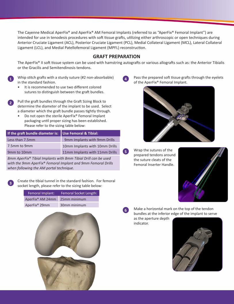
Pass the prepared soft tissue grafts through the eyelets of the AperFix® Femoral Implant.
Wrap the sutures of the prepared tendons around the suture cleats of the Femoral Inserter Handle.
Make a horizontal mark on the top of the tendon bundles at the inferior edge of the implant to serve as the aperture depth indicator.
The Cayenne Medical AperFix® and AperFix® AM Femoral Implants (referred to as “AperFix® Femoral Implant”) are intended for use in tenodesis procedures with soft tissue grafts, utilizing either arthroscopic or open techniques during Anterior Cruciate Ligament (ACL), Posterior Cruciate Ligament (PCL), Medial Collateral Ligament (MCL), Lateral Collateral Ligament (LCL), and Medial Patellofemoral Ligament (MPFL) reconstruction.
GRAFT PREPARATION
Femoral Implant: Femoral Socket Length:AperFix® AM 24mm 25mm minimumAperFix® 29mm 30mm minimum
If the graft bundle diameter is: Use Femoral & Tibial:
Less than 7.5mm 9mm Implants with 9mm Drills7.5mm to 9mm 10mm Implants with 10mm Drills 9mm to 10mm 11mm Implants with 11mm Drills8mm AperFix® Tibial Implants with 8mm Tibial Drill can be used with the 9mm AperFix® Femoral Implant and 9mm Femoral Drills when following the AM portal technique.
The AperFix® II soft tissue system can be used with hamstring autografts or various allografts such as: the Anterior Tibialis or the Gracilis and Semitendinosis tendons.

FEMORAL FIXATION
8
Holding the Inserter Handle with the safety pin facing upward, insert the AperFix® Femoral Implant through the tibial tunnel and into the femoral socket to the marked depth location.• Confirm the implant is fully seated into the femoral
socket.
Ensure the implant is in the proper position, then pull the safety pin out of the Inserter Handle.
9
10
With the Inserter Handle held firmly in place, rotate the white implant deployment knob clockwise until the deployment knob can no longer be turned and comes into contact with the purple handle.
Disengage the tendon sutures from the suture cleats.
11 Release the Inserter Handle from the implant by pulling back on the Implant Release Knob. Remove the Inserter Handle from the operating site and discard.
7
Pre-Deployed
Deployed

3
1
2
Select the Tibial Implant size to match the drilled tunnel diameter. • The Tibial Implant will come with a Tendon Expander,
Guide Wire, Cannulated Screw, and a Driver pre-loaded with the Tibial Sheaths and Sheath Holder.
Hold the Tendon Expander arms perpendicular to the tibial tunnel and wrap the sutures from the tendon bundles around the suture cleats, such that the sutures are first inserted in the lateral slits and then wrapped around the vertical cleats.
Optional: Rotating the TendonsFor orientation of the graft bundles at the tibial aperture, rotate the Tendon Expander until the tendons representing the AM bundle are positioned in the anteromedial portion of the tunnel and the PL bundle in the posterolateral portion.
Insert the Guide Wire through the Tendon Expander, into the tibial tunnel (between the tendons), and into the joint space. • Confirm the Guide Wire is in the joint space.
TIBIAL FIXATION
Place the knee in extension and maintain the graft under tension. Insert the Tibial Sheaths over the Guide Wire and into the tibial tunnel such that the cortical engagement tabs are in the 12 o’clock position. • The Tibial Sheaths
should be positioned with the tabs fully seated against the tibia.
4
Optional: If the bundles were rotated in step 2, make sure the cortical engagement tabs are positioned on the medial side of the tunnel.
Pull the Driver back along the Guide Wire to disengage from the Tibial Sheaths.
5
Remove the Sheath Holder from the Driver and securely place the Tibial Screw on the end.
6
• Verify the tabs are fully seated against the cortex.

*Refer to the product Instructions For Use (IFU) insert for a list of contraindications, warnings, and precautions.
7 Insert the Tibial Screw over the Guide Wire until the tip of the Screw engages the Sheaths. • Use the “Easy Start” feature of the Tibial Screw
by aligning the flat tip parallel with the Sheaths prior to deployment.
With forward pressure, turn the Driver clockwise until the screw head is flush with the superior rim of the cortical wall. Maintain tension on the graft to prevent loss of graft stiffness.• The Tibial Screw threads match that of the
Sheath, therefore excessive torque is not needed to engage and insert the Screw.
8
Once the Tibial Screw is completely seated between the Sheaths, remove the Driver by pulling the handle straight back. Remove the Guide Wire. • Confirm the integrity of the repair.• Trim the excess suture and tendon flush with the
tibial surface.
9
Reamer Blades
Drill Stop
TIBIAL REMOVAL STEPS 1. Use the Tibial Removal Tool to disengage the Screw from the
Sheaths by rotating counterclockwise.
2. Using a standard grasping instrument, remove the Tibial Sheaths from the tunnel one at a time.
3. Clean the tibial tunnel and joint space to expose the Femoral Implant. Tibial tunnel diameter must match Coring Reamer Diameter for Femoral Removal Option 2.
FEMORAL REMOVAL STEPS Option 1– Femoral Removal Tool
To be used intra-operatively or post surgery when there is no bony ingrowth around the implant.
1. Using the reverse threaded Femoral Removal Tool, remove the Central Screw.
2. Turn counterclockwise while pulling axially.
3. Remove the implant from the femoral socket once it has returned to its pre-deployed formation.
Option 2– Coring Reamer System To be used post-surgery when bony ingrowth prevents the
implant from being undeployed and removed.
1. Use the reverse threaded Femoral Removal Tool to remove the Central Screw by turning counterclockwise and pulling axially.
2. Insert the Alignment Guide Wire up through the center of the Femoral Implant.
3. Make sure the Drill Stop is positioned just outside of the femoral tunnel.
4. Manually walk the Coring Reamer over the Alignment Guide Wire. Ensure the Coring Reamer blades are completely over the Drill Stop before using power.
5. Core at least 30mm.
6. Using power, back the coring reamer out of the socket. It now holds the encased Femoral Implant.
• Remaining PEEK™ material can be removed from the tunnel using standard graspers.
**For more detailed removal techniques, please see our Removal Technique Guide located on our website: www.cayennemedical.com
AperFix® II Removal

16597 N. 92nd Street, Ste. 101Scottsdale, AZ 85260
p: 888.229.3661f: 888.334.4079w: www.cayennemedical.com
11601 Rev. C
Manufactured By:
AperFix® Femoral Implant with InserterModel # Item DescriptionCM-2409 9 mm x 24 mm AperFix® AM Femoral Implant with Inserter
CM-2410 10 mm x 24 mm AperFix® AM Femoral Implant with Inserter
CM-2909 9 mm x 29 mm AperFix® Femoral Implant with Inserter
CM-2910 10 mm x 29 mm AperFix® Femoral Implant with Inserter
CM-2911 11 mm x 29 mm AperFix® Femoral Implant with Inserter
AperFix® II Tibial Implant with DriverModel # Item DescriptionCM-3008 8 mm x 30 mm Tibial Implant with Driver
CM-3009C 9 mm x 30 mm Cannulated Tibial Implant with Driver
CM-3010C 10 mm x 30 mm Cannulated Tibial Implant with Driver
CM-3011C 11 mm x 30 mm Cannulated Tibial Implant with Driver
AperFix® Disposable InstrumentsModel # Item DescriptionCM-7014 Calibrated Drill Tipped Guide Wire, 2.4 mm x 14”
CM-1501 ACL Disposable Procedure Kit
CM-7609 Accessory Portal Kit with Low Profile Drill and EZ Shuttle™ Suture Loop, 9 mm
CM-7610 Accessory Portal Kit with Low Profile Drill and EZ Shuttle™ Suture Loop, 10 mm
CM-7611 Accessory Portal Kit with Low Profile Drill and EZ Shuttle™ Suture Loop, 11 mm
Ordering Information
![PIRPAG Exercises Post Transtibial Amputation Exercises Post Transtibial... · q [1] Static Quadriceps • Push your legs straight out in front of you • Push the back of your knees](https://img.dokumen.tips/doc/110x75/5af593ba7f8b9a8d1c8dc60b/pirpag-exercises-post-transtibial-amputation-exercises-post-transtibialq-1.jpg)