Embed Size (px)
Citation preview

1
FINAL TECHNICAL REPORT
September 1, 2008, through April 30, 2010
Project Title: TRANSPORT MEMBRANE CONDENSER FOR WATER AND
ENERGY RECOVERY FROM POWER PLANT FLUE GAS
ICCI Project Number: 08-1/5.1A-1
Principal Investigator: Dexin Wang, Gas Technology Institute
Project Manager: Debalina Dasgupta, ICCI
ABSTRACT
The aim of this project was to develop and test a membrane-based technology to recover
water and energy from power plant flue gas. The recovered heat and high-purity water
can be used directly to replace power plant boiler makeup water to improve its efficiency,
and the remaining part of the recovered water can be used for flue gas desulfurization
(FGD) water makeup or other plant use.
A new technology based on a nanoporous ceramic separation membrane to extract a
portion of water vapor and its latent heat from flue gases and return the recovered water
and heat to the steam cycle was developed at the Gas technology Institute, through the
use of its patented Transport Membrane Condenser (TMC). Water vapor passes through
the membrane and then is condensed by direct contact with a low-temperature water
stream. Contaminants such as oxygen and acidic gases are inhibited from passing
through the membrane by its high selectivity. The project team including Media &
Process Technology (M&P) and Cleaver-Brooks (CB), has developed the TMC for
industrial package boilers. Four prototypes are currently in operation on industrial steam
boilers, with the first prototype being in continuous operation for about three years. An
increase in boiler efficiency of 82% to 94%, 12% in fuel savings and 20% in water
savings have been reported by a customer based on the first year of operation.
In this project, a new two-stage TMC design was developed to achieve maximum heat
and water recovery from power plant flue gas. The new TMC will be applied to coal-
fired power plants that use high-moisture coals and/or FGDs. The design and bench scale
evaluation work were completed. A pilot-scale TMC unit was built and installed at GTI,
and preliminary testing completed. The pilot TMC performance will be further evaluated
at GTI with simulated flue gas from a natural gas boiler, and then later with a coal fired
power plant slip stream at a host site.
It is estimated this technology can save about 8.3 billion tons of fresh water per year, with
an associated cost saving of $4.3 billion across the United States. In Illinois alone, the
annual water savings are estimated to be 440 million tons, valued at $225 million. In
addition, boiler thermal efficiency can be increased through the use of hot water from the
TMC as a replacement for fresh cold makeup water, reducing water treatment costs.
Estimated U.S. electric power savings from this efficiency increase would total 3.0
billion kWh valued at $260 million, of which Illinois coal-fired power plants would
account for about 160 million kWh valued at $14 million.

2
EXECUTIVE SUMMARY
The objective of this project was to develop and test a membrane-based technology to
recover water and energy from power plant flue gas. The recovered high-purity water
and heat can be used directly to replace power plant boiler makeup water to improve its
efficiency, and any remaining recovered water can be used for flue gas desulfurization
(FGD) water makeup or other plant use.
Until now, there has been no practical commercial technology available for recovering
water vapor from power plant flue gas. Condensing flue gas moisture by simply
removing heat in a heat exchanger presents the problem of a large surface area
requirement for the low-temperature flue gas, and also raises the issue of equipment
corrosion by the acidic condensate. Since flue gas contaminants are retained in the
recovered water, including dissolved CO2, NO2, sulfuric, hydrochloric, nitric acids, and
even heavy metals in the case of a coal-fired plant, further processing of the condensed
water is necessary. The energy consumption associated with the additional processing of
the produced water makes this type recovery economically unattractive.
GTI has been developing a new technology based on a nanoporous ceramic separation
membrane to extract a portion of the water vapor and its latent heat from flue gases and
return the recovered water and heat to the steam cycle. This is achieved through the use
of its patented Transport Membrane Condenser (TMC). Water vapor passes through the
membrane and then is condensed in direct contact with a low-temperature water stream.
Contaminants such as CO2, O2, NOx, and SO2 are inhibited from passing through the
membrane by its high selectivity. The TMC has been developed and proven at the
industrial demonstration scale for gas-fired package boilers.
In this project, GTI has upgraded the TMC technology to a two-stage design tailored to
power plant applications. GTI has built and preliminary tested a pilot-scale two-stage
TMC test unit connected to a 3-million-Btu/h boiler and validated its performance with
simulated coal-fired flue gas at GTI laboratory. Major participants included Media &
Process Technology (M&P) of Pittsburgh, PA, who carried out studies to optimize
membrane properties for this application and Alliant Energy who provided expertise and
detailed information on coal-fired power generation facilities. Alliant Energy is expected
to provide access to a actual power plant flue gas slip stream for follow-on testing, after
pilot scale testing of the TMC is completed to further establish the feasibility of the TMC
technology for future integration into U.S. coal-fired power plants, particularly plants that
use FGD to clean up flue gas from high-sulfur Midwestern coals such as Illinois No. 6.
GTI will also seek to expand the research team to include other utilities that burn Illinois
coal.
The new two-stage TMC design developed here for power plant flue gas seeks to achieve
maximum heat and water recovery. The TMC technology will be particularly beneficial
to coal-fired power plants that use high-moisture coals and/or FGD for flue gas cleanup.
Since most power plants using Illinois coal require a FGD unit to remove SO2 from the
flue gas, the TMC may be used to process high-moisture flue gas from the FGD to

3
recover its water vapor and its latent heat to increase efficiency and decrease water
consumption. The technology is expected to save approximately 8.3 billion tons of fresh
water per year across the U.S., with an associated cost saving of $4.3 billion. In Illinois
alone, these savings would be 440 million tons of water with a value of $225 million.
Additionally, boiler thermal efficiency can be increased through the use of hot water from
the TMC replacing fresh cold makeup water for the boiler, which also reduces water
treatment cost. U.S. electric power savings from the efficiency increase could total 3.0
billion kWh valued at $260 million, of which Illinois coal-fired power plants would
account for 170 million kWh, valued at $14 million, per year.
4
OBJECTIVES
The objective of this project was to develop a membrane separation technology to
recover water vapor from power plant flue gas based on GTI's patented Transport
Membrane Condenser (TMC) technique. A small portion of the recovered water vapor
may be directly added to the boiler feed water loop to replace expensive fresh makeup
water and simultaneously improve power plant energy efficiency. The rest of the
recovered water can be made available for plant use such as cooling tower water makeup
or FGD makeup. About 90% of the cooling water stream available for power plant
application can be cost-effectively recovered through implementation of this technology.
The technology is particularly advantageous when applied to high-moisture-content coals
and to power plants that use FGD's, due to increased moisture level in the stack gases.
The TMC approach can also be also used to recover water from the exhaust stream
emanating from drying high-moisture coals. Three phases that were scheduled for the
this project included evaluation of membrane performance and development of a two-
stage TMC design concept in phase 1; design, build and test a pilot-scale TMC at GTI’s
laboratory in phase 2; and test the pilot-scale TMC with a power plant slipstream and
develop a scale-up design and commercialization plan in phase 3.
Under this ICCI sponsorship, proposed phase 1 work and part of phase 2 work has been
completed and the tasks proposed under the project are listed below:
Task 1.0 - Design Basis and Modeling
Model and evaluate the two-stage TMC water recovery concept by using analytical and
numerical methods, resulting in a design basis for power plant application.
Task 2.0 - Membrane Performance Optimization and Lab Testing
Optimize ceramic membrane performance for flue gas water recovery application.
Task 3.0 - Design and Fabrication of Pilot-Scale Unit
Design and fabricate the pilot-scale test system for TMC technology applicable to flue
gas from coal-fired power plants.
INTRODUCTION AND BACKGROUND
This project aims to develop a new technology for recovering water vapor and its latent
heat from power plant flue gases by utilizing a nanoporous ceramic membrane device –
the Transport Membrane Condenser or TMC designed earlier by Gas Technology
Institute (GTI) to recover water vapor and its latent heat from flue gas of industrial
boilers [1]. In this project, the TMC technology was further investigated and optimized
for application to coal-fired power plants.
In the TMC, water vapor from flue gas passes through a permselective membrane, shown
in Figure 1, and is condensed by direct contact with low-temperature water. Thus, the
transported water is recovered along with virtually all of its latent heat. The conditioned
flue gas leaves the TMC at a reduced temperature and relative humidity below saturation.

5
The TMC for coal-fired
flue gas can be separated
into two stages depending
on the ultimate
application of the
recovered water. The
first stage of the TMC
can be designed to direct
a portion of the recovered
flue gas moisture directly
into the turbine steam
condensate stream. This
part of hot water from the
TMC can replace
essentially all the cold
makeup water for the
boiler feed water stream
to improve the boiler
efficiency. The second
stage of the TMC may
then recover a large
amount of water from the
flue gas and add it into the
plant cooling water stream.
This portion of recovered water can replace part of the cooling tower water makeup, or it
can be used in other processes of the power plant such as FGD makeup water. In
industrial package boilers, the low-temperature water stream for TMC operation is
provided by the fresh makeup water. Seeking to apply the TMC to coal-fired power
plants, where makeup water is a much smaller portion of the total boiler feed water
stream, GTI has analyzed typical water circuits in a power plant to identify the
appropriate streams for TMC use. Based on the collected data, it is believed a suitable
source of low temperature water for the TMC first stage is a portion of the turbine steam
condensate, typically at 90-110°F. This temperature would be adequate to provide the
driving force for water transport across the membrane, a major factor for making the
technology successful. For the TMC second stage, part of the available steam condenser
cooling water can be used, which is typically at 70-90°F or lower. Part of this larger
amount of cooling water flowing through the TMC will help the TMC to extract a
significant amount of water from flue gas.
Water vapor recovery from flue gases by membrane separation technology is still a new
area. It had not been the subject of a focused inquiry until GTI began working on the
DOE-sponsored ―Super Boiler‖ project in 2000. After extensive study, GTI selected a
ceramic membrane for the TMC that was successful in meeting the energy efficiency
goal by transporting part of the moisture and its latent heat from flue gas. GTI has
already demonstrated the use of the TMC in four industrial gas-fired boilers for long-term
operations, with the first unit being in continuous operation for nearly three years with no
Figure 1 - TMC concept
Water Vapor Laden
Flue Gas Inlet
Water Vapor Depleted
Flue Gas Outlet
60 t
o
80Å
500Å
~0.4μm
Tube Side
TMC Element
Shell Side TMC Element
Cold Water
Inlet
Hot Water
Outlet
TMC Membrane Cross Section
w/ Pore Sizes of the Layers
Capil
lary
Condensati
on o
f W
ate
r
Occurs
in t
he S
urf
ace P
ore
s
Water (and Heat) Flow

6
detectable performance degradation. The customer has confirmed a 12% in fuel savings
and 20% in makeup water savings. However, economic analysis showed that the earlier
version of the TMC (version 1.0) was too expensive to manufacture, assemble, and
maintain. As a part of this project GTI has developed a version 2.0 design of the TMC
for industrial and commercial boilers with more cost-effective characteristics. GTI has
also begun the process of optimizing the TMC for commercial sale. Besides Media &
Process Technology (M&P) of Pittsburgh PA, the project team also includes Alliant
Energy, a major utility company in the Midwest, which has many large coal-fired power
plants in three states. Alliant continues to provide power plant engineering experience
and a power plant boiler flue gas slip stream to demonstrate the TMC on actual coal-fired
flue gas. Alliant has also participated in a project sponsored by the U.S. Department of
Energy National Energy Technology Laboratory (DOE-NETL) to develop this
technology for power plants.
In tests with industrial gas-fired boilers, GTI has demonstrated up to 45% recovery of
flue gas moisture, but this is limited by the available cooling water which, for industrial
boilers, is provided by the fresh boiler makeup water. In industrial and commercial
applications, this makeup water typically ranges from 10 to 100% of the total boiler feed
water. Besides providing a lower temperature turbine steam condensate, the large
amount of cooling water (typically 25 times of the boiler feed water flow rate) can
provide a much larger driving force for the TMC, such that up to 90% moisture removal
from the flue gas is possible. For a power plant equipped with a wet FGD, flue gas
exiting at 160 to 180°F and nearly 100% relative humidity contains much larger amount
of water vapor than in the flue gas from an industrial gas-fired boiler. For a power plant
equipped with a dry FGD, the flue gas moisture content is still comparable with the
industrial gas-fired flue gas, with a dew point at 130 to 140°F, or about 20% in volume of
water vapor in the flue gas stream.
As mentioned above, through further study, GTI developed a version 2.0 TMC design
with shell side flue gas and tube side water flows. With water flowing inside the tubes,
the water side management allows a more flexible design, with the TMC to be designed
with several passes (Figure 2 shows a three-pass design). Hot water can be pumped out
from the lower section of the TMC instead of the upper section, which results in
simplified water level controls. Another important advantage of the new design is that
flue gas now flows upwards instead of downwards as in the previous TMC, allowing the
unit to be mounted directly on top of a boiler stack without the lengthy ductwork needed
to direct the flue gas downwards and then reverse direction to go upwards to the
atmosphere. This greatly reduces the installation cost. Also shown in Figure 2 is the
larger tube count of the new membrane module – a four-fold increase – which reduces
manufacturing and assembly cost. An optimum spacing between tubes allows flue gas to
flow through with a favorable tradeoff between turbulence and pressure drop. The tubes
are protected from both sides by metal plates, which also reinforce the overall module
structure strength. For a typical 300 HP industrial boiler, only 9 of these modules is
needed instead of 94 modules in the original TMC design, which facilitates assembly and
service.

7
Figure 2 also shows the first Version 2.0 TMC unit installed on a 200HP boiler. The
redesigned TMC is more efficient and cost-effective, and the modular design much easier
to assemble and maintain. GTI has already commercialized the TMC technology for an
industrial boiler and licensed its patent to Cannon Boiler Works INC. The TMC can be
also applied to other industrial waste heat streams with higher moisture content and the
research team is currently involved in formulating a pathway to address a larger market.
Figure 2 - New Membrane Module (left), Version 2.0 TMC Design (middle), and an installed unit
for a 200HP boiler (right)
Benefits of the technology
The economic benefits of water vapor removal from flue gas are substantial. GTI
calculates a reduction in the flue gas dew point from 140°F down to 100°F, which
corresponds to recovering 84 lb/h water per 1 million Btu/h firing rate. For the year
2000, the net U.S. electric power generation was 3,802 billion kWh, of which coal-fired
generation was 1,966 billion kWh, and natural gas-fired generation was another 613
billion kWh. [2]. This water recovery technology could be used for both coal- and gas-
fired power plants and up to 2,579 billion kWh of capacity could be impacted by this
technology. Assuming a 35% baseline fuel-to-electricity efficiency, the total firing rate is
estimated at 25 trillion Btu/h. The corresponding total water saving, if this technology
were applied to all U.S. power generation, would be 8.3 billion tons per year. At a
typical treated water price of $0.52/ton [3], the total annual U.S. cost saving in water
alone would be $4.3 billion/year. In Illinois alone, these savings would be 440 million
tons of water with a value of $225 million. Additionally, the use of TMC can increase
boiler thermal efficiency by 0.1-0.2% as described above by recovering the water vapor
latent heat. This efficiency increase would increase power output by 3.0 billion kWh
nationwide, of which Illinois coal-fired power plants would account for about 160 million
kWh per year.
Commercial market and benefit to procedures and users of Illinois coal
The TMC can be applied to coal-fired power plants that use high-moisture coals and FGD
to process the high-moisture flue gas from the FGD to recover its water vapor along with
the tremendous latent heat therein. This recovery will increase plant efficiency and save

8
water consumption. There is a substantial environmental and economic benefits
projected to the power industry from this technology. As detailed above, the technology
can save about 8.3 billion tons of fresh water per year, with an associated cost saving of
$4.3 billion per year, plus 3.0 billion kWh of electricity with a value of $260 million from
increased boiler efficiency. In Illinois, these savings would total 440 million tons of
water with a value of $225 million to go along with 160 million kWh of power output
with a value of $14 million per year.
Competitive technology
Until now, there has been no practical commercial technology available for recovering
water vapor from power plant flue gas. Condensing flue gas moisture by simply
removing heat in a heat exchanger presents the problem of a large surface area
requirement for the low-temperature flue gas, and also raises the issue of equipment
corrosion by the acidic condensate. The condensed water needs to be processed to be
used for plant use, because flue gas contaminants are retained in the recovered water,
including dissolved CO2, NO2, sulfuric, hydrochloric, and nitric acids, and even heavy
metals in the case of a coal-fired plant. Dehumidification technologies based on liquid
desiccants involves multiple unit operations to accomplish the water extraction, resulting
in high equipment cost and system complexity for process control and reliable operation.
The TMC technology requires less equipment and less complex process control than
competing methods. With a demonstrated high separation ratio of the membrane
technology, the recovered high-purity water can be directly used for boiler feed water, as
demonstrated in industrial boilers at customer sites. Corrosion does not pose a problem
with the ceramic membrane surface, and the mode of operation prevents the formation of
condensate on the gas side. The TMC also requires less heat transfer surface area than
conventional indirect heat exchangers. In addition to heat conduction through the
membrane wall, convective heat transfer also plays a big role in the TMC because of the
transport of condensed water through the membrane that carries heat with it.
EXPERIMENTAL PROCEDURES
Through concept design and modeling, based on data provided by a utility partner, ranges
for parametric ranges for testing were determined. Modeling work included the impact of
recovered water heat on the steam-power cycle and cooling tower water stream, and CFD
optimization for the two-stage TMC design to distribute heat and water flow between the
two stages.
Two test setups were used in the project work. Figure 3 shows the single membrane
module test rig that has been used at GTI to determine a single membrane module water
vapor recovery performance from hot flue gas. The lab test membrane module can be
constructed with as many as 100 membrane tubes. The downstream flue gas coolers
section allows addition of gas components like SO2, NO2, CO2, and H2O components to
the flue stream to match any specific flue gas condition. This test rig was used for
optimization and selection for different membrane pore sizes and structures for

9
TMC/stage1 and TMC/stage2 performance.
Figure 3 – Single Membrane Bundle Lab Test Rig (side and front views)
Figure 4 shows the pilot scale TMC test setup for water recovery in the GTI industrial
boiler test lab. The test system at GTI includes an existing 3-million-Btu/h natural gas-
fired boiler with oil backup, an economizer and feed water tank, and a flue gas
conditioning setup which can add gas components like SO2, NO2, CO2, and H2O
components to match coal-fired flue gas along with two-stage TMC.
Both the test setups are equipped with temperature, pressure, humidity, flow rate
measurements and complete gas analysis. Data generated through experiments were
collected using a data acquisition system for on-line display and storage. Water quality
was sampled for analysis of dissolved components and particulates. The recovered water
mass rate was measured from the difference of TMC inlet and outlet water flow rates
and/or the flue gas humidity difference. Energy savings were calculated from TMC inlet
and outlet water temperature and mass flow rate changes.
The TMC was modified to incorporate a 34‖ long module instead of an 18‖modeule that
had been previously developed for industrial boiler flue gas heat/water recovery. The
membrane tube arrangement was changed to inline design, for ease of tube surface
cleaning. The TMC module was reinforced in the center with two pairs of metal bars to
ensure the integrity of the module structure. Additional pictures of the module and a
close-up view of the TMC pilot unit can be seen in Figure 5.

10
Gas/oil-fired 3 million Btu/hr Boiler
Economizer
Flue gas
Stack
Cold Water
Water
Hot Water
TMC/stage 2
Flue Gas Conditioner (add in SO2,NOx,CO2, H2O,etc to
match Coal-fired flue gas)Feed Water
Tank
(Deaerater)
Water
Quality
Check
Points
TMC/stage 1 Cold Water
Warm Water
Figure 4 – Pilot-Scale TMC Test Setup Schematic (left), installed test system picture (right)
Figure 5 – A close-up view of the TMC pilot unit (left), and large longer membrane module
(right)
RESULTS AND DISCUSSION
Task 1.0 Design Basis and Modeling
Data Collection
Detailed power plant related data was collected by RMT/Alliant Energy. Data obtained

11
included flue gas parameters (flow rate, temperature, composition, pressure, etc.) before
and after a FGD unit, steam condensate and cooling water parameters (temperature and
flow rate), potential demineralized water usage (boiler makeup, heating system losses,
bearing cooling, FGD, etc) in a power plant, and fly ash data (particulate concentration
and size, before and after an ESP). As an example, some of the collected data is shown
in Table 1 and Table 2. The purpose of this exercise was to determine the amount of
water vapor typically available from a flue gas stream and estimate a recoverable amount
with the available cooling sources. Additionally, application of this recovered water in
the power plant water circuits besides boiler makeup and cooling water makeup was also
identified. This is because the recovered water is basically mineral free and of high
quality, and we should find a better using place than cooling water makeup.
More information about typical power plant operating data obtained is listed below to
show the benefit analysis if this TMC technology is used for any specific boiler. Data
was compiled from 3 power plants burning PRB coal on a KPPH basis, starting 1/1/09
and ending 8/11/09. For all the three plants, daily make-up water quantity to the
condenser was identified, and potential savings calculated based on this number and the
current cost of producing demineralized water. For one plant the potential savings were
calculated assuming use of recovered water instead of city water to eliminate the need of
an additive that is required to run the RRI/SNCR injection system with city water.
A 220 MW T-Fired Boiler
• Demineralized water cost $6.50/Kgal
• Averaged 70,000 gallons of make-up water per day.
• Potential cost savings using recovered water instead of producing demineralized water
for make-up is $130K per year.
A 675 MW T-Fired Boiler
• Demineralized water cost $6.50/Kgal
• Averaged 92,000 gallons of make-up water per day.
• Potential cost savings using recovered water instead of producing demineralized water
for make-up is $210K per year.
A 330 MW Cyclone-Fired Boiler
• Demineralized water cost $4.00/Kgal.
• Averaged 70,000 gallons of make-up water per day.
• Potential cost savings using recovered water instead of producing demineralized water
for make-up is $91K per year.
• Urea additive $70/Ton with an average of 9 tons/day being used.
• Additional savings on additive if using recovered water in place of city water is $180k
per year.

12
Table 1: Typical flue gas composition for a FGD unit by Alliant Energy
Parameter
Total Unit Inlet
Flue Gas
Inlet Flue Gas
per Module
Outlet Flue
Gas per
Module
Total Unit
Outlet Flue
Gas
Flow, acfm 1520707 380177 330588 1322350
scfm (68°F-
14.7psia) 1047496 261874 291932 1167728
Temperature, °F 300 300 125 125
Pressure, inwg 6.5 6.5 1 1
Pressure, psia 14.57 14.57 14.38 14.38
Air, lb/hr 3692128 923032 967328 3869310
CO2, lb/hr 866542 216636 220892 883569
H2O, lb/hr 257312 64328 118621 474483
SO2, lb/hr 24770 6193 124 495
HCl, lb/hr 421 105 0 0
Fly Ash, lb/hr 168 42 21 84
Total, lb/hr 4841342 1210335 1306985 5227942
Table 2: Typical Power Plant Water Consumptions
Water Usage in Power
Plants
Unit # 1 Unit # 2 Unit # 3 Unit #4
T-Fired 530
MW
Cyclone 330
MW
Wall Fired
400 MW
T-Fired
390 MW
Make-Up Water 44 kpph 21.5 kpph 29.9 kpph 90 kpph
Water Cannon NA NA NA
Water Lance RO or Serv.
Water
NA NA NA
Sootblowing Steam Make-
Up
22 kpph NA 11.9 kpph incl. in
make-up
RRI/SNCR NA 7.6 kpph NA NA
Water Storage boiler fill &
emergency -
4x boiler fill
boiler fill &
emergency -
4 x boiler
fill
boiler fill
&
emergency
- 4 x
boiler fill
boiler fill
&
emergency
- 4 x boiler
fill
Feed Water closed loop closed loop closed
loop
closed loop
Bearing Cooling Water closed loop closed loop closed
loop
closed loop
FGD water NA NA NA 257 kpph
Condenser Circulating
Water Flow
NA NA 185 kpph 175 kpph
Service Water Flow NA NA NA NA
Notes:
1. If Sootblowing Steam is listed it is already accounted for in the Make-up water. It is

13
just showing how much of the make-up is due to sootblower consumption.
2. Water Storage - is part of emergency and reserve for start-up activities. Drum blow
downs are open for boiler water chemistry control.
3. Make-up water includes normal blow downs, leaks through safety or other valves,
plant heating systems and other open-loop steam usages.
4. Service Water flows and usage is depending on plant specific layout and location. It's
sources are river, lake, city, deep well water sources.
A Two-stage TMC Concept Design for Power Plant Water/Steam Cycle
Although the TMC technology was initially developed for natural gas-fired industrial
boilers, it is adaptable to coal-fired utility boilers that burn high moisture content coals.
Figure 6 shows a schematic for integrating the TMC water recovery unit in a typical
power generation boiler steam turbine loop. For the two-stage TMC unit to maximize its
function for recovering water and heat, two separate cooling water streams is used. On
the water side, the first-stage TMC inlet water will be obtained from steam condensate
from the condenser, and its outlet water with recovered water vapor and associated latent
heat from flue gas will go to the deaerator for boiler water makeup. The second-stage
TMC inlet water will be a part of the condenser cooling water stream. The outlet water
from this TMC stage will then be routed to go back to the cooling water stream with extra
recovered water from the flue gas. On the flue gas side, the TMC is situated between the
FGD unit and the stack.
Boiler
Economizer
Air Preheater
TMC/Stage2
flue gas
Steam
Low Pressure
Water Heater
Flue Gas
Desulphurization
Stack
flue gas
Steam
Turbine
Condenser
Cooling
Water In
Cooling
Water Out Condensate
High Pressure
Water Heater
Stage #M
Steam Bleed
Stage #N
Steam Bleed
Water
Hot Recovered
Water
Steam/vapor Flow
Water Flow
Flue gas flow
TMC/Stage1
Dearator
With Recovered Water
Cooling Water to TMC
Figure 6 – Power Plant Flue Gas Water Recovery with a Two-Stage TMC

14
The impact of this water on the overall plant water conditioning requirements shows, it
will have minimal impact on water treatment needs because of the high selectivity of the
membrane under capillary condensation operation.
Figure 7 shows the potential power station that can host our field evaluation test. The
location of theTMC based heat/water recovery system will be in the horizontal stack area
before going to the main stack.
Figure 7– Columbia Power Station (left) and potential location for TMC before the stack (right)
Analysis, Modeling and Concept Design Summary
The two-stage TMC concept design for a power plant flue gas stream was evaluated after
analysis of collected data. Two separate cooling water streams are used for the for the
two-stage TMC concept. TMC/stage1 utilizes the turbine condensate as cooling stream
to recover both water and heat from the incoming hot flue gas stream, and sends the hot
water to the deaerator as boiler makeup water. This water is at a higher temperature
(130˚F to 160˚F depending on incoming flue condition) than a regular makeup water and
overall boiler efficiency can be expected to increase about 0.5%. Estimated recovered
water quantity was more than sufficient for boiler makeup (typically less than 1%
steaming rate) and the excess mineral free water can be used to makeup heating system
losses, bearing cooling losses, in addition to being a part of FGD water supply.
TMC/stage2 uses part of the condenser cooling water stream to recover a large amount of
water and part of the heat from the flue gas stream coming out of TMC/stage1. This heat
could be extracted later for coal drying or other heating purpose before the water stream
joins the main cooling water stream. The large amount of recovered water can be used as
cooling water makeup, which has additional benefits of reducing blow down losses.
Task 2.0 Membrane Performance Optimization and lab testing
Membrane performance optimization test was done on a modified TMC setup for testing
a single TMC membrane module, built with seventy-eight 18‖-long membrane tubes.
Membrane module building method was evaluated by using different adhesives, different
assemble part materials, and finally a two-part epoxy based adhesive and a glass-filled
epoxy based assemble part material were selected for their combined bonding strength at

15
this temperature and humidity condition. Practical TMC membrane modules can be built
with this method fast and economically.
TMC stage 1 membrane module (pore size 8.5 and 15 nm) test results
The stage 1 membrane module test was designed to find out if these membrane sizes
were adequate for TMC/stage 1 application. The first stage TMC uses a portion of the
turbine steam condensate stream (typical temperature is 90-110⁰F) as cooling water to
recover a portion of the heat and water from the flue gas. After passing through the
TMC, the water temperature is raised by about 20 to 50⁰F depending on the water flow
rate, and the recovered water can be added into this stream of water. The increased
amount of hot water from the TMC can replace essentially all the cold makeup water for
the boiler feed water stream to improve the boiler efficiency.
Based on inlet flue gas conditions (inlet temperature and dew point), the water flow rate
and water inlet temperature can be controlled to achieve the required water conditions
(makeup water flow rate and temperature). For typical natural gas flue conditions, the
current 8.5 nm membrane pore size is appropriate for TMC/stage 1. Figure 8 shows that
different membrane pore sizes do not have much impact on the TMC water and heat
transfer performance.
Figure 8 –TMC/Stage 1 different membrane pore size effect on water and heat transport
TMC membrane module (pore size 15 nm) high moisture test results
The TMC was tested for high moisture flue gas. By injecting water into the natural gas
flue gas stream, the flue gas dew points were increased from 134˚F to 150˚F, with a
corresponding moisture volume increase from 16.8% to 25.3%. Figure 9 shows the
results and they indicate that both the moisture transport rate and heat recovery are more
than doubled, which proves the TMC can be more effective when being used for high
moisture waste heat exhausts.

16
These test results confirmed the theoretical analysis that high moisture content flue gas
can provide high vapor transport driving force and create a higher water transfer rate.
Figure 9 – High moisture flue gas—water transport and heat recovery
TMC/stage1 result summary
Two membrane pore sizes (8nm and 15nm) were investigated for their water and heat
transport performance at different flue gas conditions (temperature, moisture contents),
different cooling water conditions (flow rate, inlet temperature) and different membrane
permeate side vacuums. A larger pore size is favored for high moisture content
conditions where high water transport rate is needed, but a smaller pore size is favored
for most of the cases of TMC/stage1 flue gas condition so as to create a better capillary
condensate effect.
TMC stage 2 membrane module (pore size 15 and 25 nm) test results
This test was designed to investigate the adequacy of membrane sizes for a TMC/stage 2
application. The TMC/stage 2 receives low temperature flue gas from a TMC/stage 1
with low moisture content. However since the flue gas is at a high relative humidity
condition it is favorable to recover a large portion of the water. Figure 10 shows a data
plot for different flue gas inlet temperatures and different averaged cooling water
temperatures (water flow rate is already considered in this parameter). Under these
testing conditions, no performance difference on water and heat transfer for the two
membrane pore sizes were noted. Therefore a 15nm pore size membrane is suggested for
a TMC/stage 2 application since a smaller pore size increases rejection of contaminants
and encourages earlier capillary condensation.
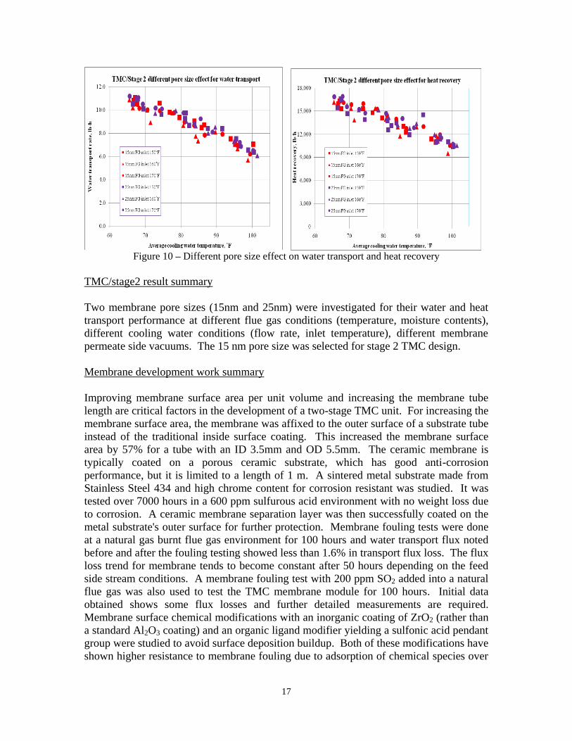
17
Figure 10 – Different pore size effect on water transport and heat recovery
TMC/stage2 result summary
Two membrane pore sizes (15nm and 25nm) were investigated for their water and heat
transport performance at different flue gas conditions (temperature, moisture contents),
different cooling water conditions (flow rate, inlet temperature), different membrane
permeate side vacuums. The 15 nm pore size was selected for stage 2 TMC design.
Membrane development work summary
Improving membrane surface area per unit volume and increasing the membrane tube
length are critical factors in the development of a two-stage TMC unit. For increasing the
membrane surface area, the membrane was affixed to the outer surface of a substrate tube
instead of the traditional inside surface coating. This increased the membrane surface
area by 57% for a tube with an ID 3.5mm and OD 5.5mm. The ceramic membrane is
typically coated on a porous ceramic substrate, which has good anti-corrosion
performance, but it is limited to a length of 1 m. A sintered metal substrate made from
Stainless Steel 434 and high chrome content for corrosion resistant was studied. It was
tested over 7000 hours in a 600 ppm sulfurous acid environment with no weight loss due
to corrosion. A ceramic membrane separation layer was then successfully coated on the
metal substrate's outer surface for further protection. Membrane fouling tests were done
at a natural gas burnt flue gas environment for 100 hours and water transport flux noted
before and after the fouling testing showed less than 1.6% in transport flux loss. The flux
loss trend for membrane tends to become constant after 50 hours depending on the feed
side stream conditions. A membrane fouling test with 200 ppm SO2 added into a natural
flue gas was also used to test the TMC membrane module for 100 hours. Initial data
obtained shows some flux losses and further detailed measurements are required.
Membrane surface chemical modifications with an inorganic coating of ZrO2 (rather than
a standard Al2O3 coating) and an organic ligand modifier yielding a sulfonic acid pendant
group were studied to avoid surface deposition buildup. Both of these modifications have
shown higher resistance to membrane fouling due to adsorption of chemical species over

18
alumina based membrane systems.
Task 3.0 - Design and Fabrication of Pilot-Scale Unit
The objective of this task was to design and fabricate the pilot-scale test system for TMC
technology applied to flue gas from coal-fired power plants. As shown in Figure 4 and
Figure 5, the fabricated pilot TMC system was installed with complete control and
instrumentation systems. A data acquisition system was designed for this test setup and
used to collect all relevant data. System shakedown was completed, which included a
boiler to supply flue gas to the TMC system, a water softener to supply high quality water
to TMC to simulate steam condensate, mechanical integrity checking, and control and
data acquisition system commissioning.
After the installation and shakedown, several test runs were performed to determine
preliminary TMC performance. Table 3 lists the 6 cases that have been tested. Both
stage 1 and stage 2 of the TMC unit realized high water vapor transfer rates, and the total
vapor transport was noted to be 65% of the total moisture in the flue gas. Along with the
water vapor transportation, significant waste heat was also transferred to the water side.
The stage 1 TMC water was heated up to 116˚F, which may contribute to higher boiler
efficiency if used for boiler makeup water.
Table 3: Preliminary Test Results
Test April 13-14 2010
Test Date 13-Apr 14-Apr 14-Apr 14-Apr 14-Apr 14-Apr
Case # 1 2 3 4 5 6
Natural gas flow rate SCFH 2250 2250 2250 2250 2250 2250
O2 at stack (dry) % 5.11 5.11 5.11 5.29 5.29 5.29
Flue inlet T to LPE 206.33 204.31 196.84 189.97 183.43 185.17
Flue inlet T °F 146.98 149.04 143.79 143.45 137.50 147.43
Flue inlet Humidity % 100.00 98.00 97.77 98.70 100.00 100.00
Flue inlet dew point °F 130.91 131.11 129.67 129.29 130.27 131.97
Flue inlet vapor wt% % 10.23 10.29 9.88 9.78 10.05 10.55
Flue stage 1 outlet T °F 124.71 127.31 123.26 122.73 123.84 128.58
Flue stage 1 outlet
Humidity % 99.4 100.1 100.1 93.2 99.1 91.7
Flue stage 1 outlet dew
point °F 122.0 124.9 121.0 121.7 123.1 126.2

19
Flue stage 1 outlet vapor
wt% % 7.9 8.6 7.7 7.9 8.2 9.0
Flue stage 2 outlet T °F 95.6 97.2 93.6 96.1 96.3 97.8
Flue stage 2 outlet
Humidity °F 99.9 99.8 99.5 99.9 100.0 99.7
Flue outlet dew point °F 93.4 94.6 92.0 95.6 95.2 96.5
Flue stage 2 outlet vapor
wt% % 3.3 3.5 3.2 3.6 3.5 3.7
Overall Flue pressure drop 0.8 0.9 0.9 0.5 0.5 0.5
Stage 1 water FR gpm 5.8 7.0 6.6 7.0 6.7 4.3
Stage 1 water inlet T °F 84.0 95.0 81.7 93.0 91.6 100.9
Stage 1 water outlet T °F 105.1 109.4 101.6 107.2 107.6 119.0
Stage 2 water FR gpm 10.8 10.0 9.9 13.8 13.9 10.0
Stage 2 water inlet T °F 75.3 71.7 69.3 80.4 79.9 70.9
Stage 2 water outlet T °F 93.2 93.3 88.9 93.9 94.1 95.6
Calculated Parameters
Stage 1 water transferred lb/h 50.7 36.7 47.6 42.4 41.0 35.3
Stage 2 water transferred lb/h 100.7 113.1 99.2 94.8 103.3 116.7
Total water transferred lb/h 151.3 149.8 146.8 137.2 144.3 152.0
Total water transferred % 67.3 66.2 67.6 63.3 64.7 65.0
Stage 1 Water enthalpy
change Btu/h 61067 50207 65841 49403 53556 38427
Stage 1 Flue enthalpy
change Btu/h 77295 61653 70822 65302 60388 59299
Stage 2 Water enthalpy
change Btu/h 96245 107595 96251 92367 98127 122864
Stage 2 Flue enthalpy
change Btu/h 131059 144153 128139 121781 131873 149068
CONCLUSIONS AND RECOMMENDATIONS
Detailed coal power plant information was collected by RMT/Alliant Energy, which
mainly included flue gas parameters with and without FGD units, steam condensate and
cooling water parameters, and potential demineralized water usage in a power plant.
Based on these information, the two stage TMC concept was evaluated and developed
such that it can recover both heat and water for boiler makeup and other plant uses.

20
Three membrane pore sizes were studied experimentally for their transport performance
and proper pore sizes for each TMC stage were determined. Natural gas flue gas with
SO2 addition was used to simulate a coal combustion flue gas with minimum impact
noted to the ceramic membrane. Membrane chemical modifications were studied to
prevent membrane fouling and increasing membrane surface area in a unit volume.
The pilot-scale TMC unit and test system has been designed according to the above
study, and fabrication and installation were done in the GTI combustion laboratory.
Shakedown tests were performed and a complete control and data acquisition system was
installed. Preliminary data has been obtained through the first batch of test runs, and the
initial data collected indicates that the whole system is working according to the design.
The following tasks are further recommended for testing the TMC's feasibility under
coal-fired power plant conditions in order to evaluate its commercialization potential.
Task 4.0 - Testing and Performance Validation of Pilot-Scale Unit at both GTI and a
power plant slip stream
The objective of this task is to test the TMC water transport and heat recovery
performance at GTI for different flue gas conditions corresponding to flue gas properties
in different coal-fired power plants with both wet and dry FGD units. Flue gas inlet and
outlet humidity and temperature measurements, direct water flow rate measurement
through the TMC unit, analyses of the recovered water to confirm its quality, and the heat
and water recovery rate will be the main parameters to determine the TMC unit's
performance. A pilot TMC will then be installed in a coal power plant to process a slip
stream of its flue gas, to prove its real-world operating performance.
Task 5.0 - Scale-Up Design Investigation
Scaling algorithms will be developed under this task for application of the TMC
technology to a typical commercial coal-fired power plant.
Task 6.0 – Technology Transfer and Commercialization Plan
A path for commercial deployment will be formulated under this task.
REFERENCES
1. DOE Award Number DE-FC07-00ID13904
2. Electric Power Annual 2000, Volume II.
3. http://www.watertechonline.com

21
DISCLAIMER STATEMENT
This report was prepared by Dexin Wang, Gas Technology Institute, with support, in
part, by grants made possible by the Illinois Department of Commerce and Economic
Opportunity through the Office of Coal Development and the Illinois Clean Coal
Institute. Neither Dexin Wang & Gas Technology Institute, nor any of its subcontractors,
nor the Illinois Department of Commerce and Economic Opportunity, Office of Coal
Development, the Illinois Clean Coal Institute, nor any person acting on behalf of either:
(A) Makes any warranty of representation, express or implied, with respect to the
accuracy, completeness, or usefulness of the information contained in this report,
or that the use of any information, apparatus, method, or process disclosed in this
report may not infringe privately-owned rights; or
(B) Assumes any liabilities with respect to the use of, or for damages resulting from
the use of, any information, apparatus, method or process disclosed in this report.
Reference herein to any specific commercial product, process, or service by trade name,
trademark, manufacturer, or otherwise, does not necessarily constitute or imply its
endorsement, recommendation, or favoring; nor do the views and opinions of authors
expressed herein necessarily state or reflect those of the Illinois Department of
Commerce and Economic Opportunity, Office of Coal Development, or the Illinois Clean
Coal Institute.
Notice to Journalists and Publishers: If you borrow information from any part of this
report, you must include a statement about the state of Illinois' support of the project.