Embed Size (px)
Citation preview

Transparency with Deferred Shading
C H R I S T I A N M A G N E R F E L T
Bachelor of Science Thesis Stockholm, Sweden 2012

Transparency with Deferred Shading
C H R I S T I A N M A G N E R F E L T
DD143X, Bachelor’s Thesis in Computer Science (15 ECTS credits) Degree Progr. in Computer Science and Engineering 300 credits Royal Institute of Technology year 2012 Supervisor at CSC was Mårten Björkman Examiner was Mårten Björkman URL: www.csc.kth.se/utbildning/kandidatexjobb/datateknik/2012/ magnerfelt_christian_K12050.pdf Royal Institute of Technology School of Computer Science and Communication KTH CSC SE-100 44 Stockholm, Sweden URL: www.kth.se/csc

AbstractTransparency with Deferred Shading using Alpha-blending is a proto-type that enables use of the Deferred Shadings technique to render trans-parent objects. The main feature of presented prototype is the abilityto render transparent object in a post-pass using a front renderer withalpha-blending. A satisfactory performance of this designed method isdemonstrated both for rendering speed as well for it being an artifactfree for scenes with a low amount of lights.

Referat
Vi har skapat en prototyp som med Alpha-blending, tillsammans medDeferred Shading, kan rendera transparenta objekt. Vad som känneteck-nar vår prototyp är att den bygger på front rendering som renderar allatransparenta objekt i en s.k. post iteration. Vi har visat att vår metodär artefakt lös samt inom acceptabel hastighet kan rendera scener medett lågt antal ljuskällor.
Contents
1 Introduction 1
2 Background and related work 3
3 Algorithm overview 53.1 Basic functions . . . . . . . . . . . . . . . . . . . . . . . . . . . . . . 5
3.1.1 Alpha-blending . . . . . . . . . . . . . . . . . . . . . . . . . . 53.1.2 Blinn-Phong Shading . . . . . . . . . . . . . . . . . . . . . . 6
3.2 Front Rendering . . . . . . . . . . . . . . . . . . . . . . . . . . . . . 63.3 Deferred Shading . . . . . . . . . . . . . . . . . . . . . . . . . . . . . 7
4 Implementation 94.1 Deferred shading with Front Rendering . . . . . . . . . . . . . . . . . 94.2 OpenGL Extentions . . . . . . . . . . . . . . . . . . . . . . . . . . . 114.3 G-Buffer and P-Buffer . . . . . . . . . . . . . . . . . . . . . . . . . . 114.4 Sorting . . . . . . . . . . . . . . . . . . . . . . . . . . . . . . . . . . . 11
5 Results 135.1 Test Model . . . . . . . . . . . . . . . . . . . . . . . . . . . . . . . . 135.2 Performance . . . . . . . . . . . . . . . . . . . . . . . . . . . . . . . . 155.3 Image Quality . . . . . . . . . . . . . . . . . . . . . . . . . . . . . . . 21
6 Conclusion and future work 236.1 References . . . . . . . . . . . . . . . . . . . . . . . . . . . . . . . . . 246.2 Statement of collaboration . . . . . . . . . . . . . . . . . . . . . . . . 26


Chapter 1
Introduction
Deferred shading has become a popular technique often used for development ofmain stream video-game applications. The deferred shading technique renders ascene in two passes, submitting only the geometry in the first and calculating light-ing in the second. The first pass renders a screen space representation of the scenewhich is later saved in different buffers. These buffers are later used to calculatelighting in the second pass. Doing so reduces the amount of lighting calculationsneeded when the amount of light sources is high. However, handling transparencyhas been a major disadvantage of the deferred shading techniques since the intro-duction of the concept in computer graphics. In the first pass a visbility test is usedto speed up and prevent rendering of occluded geometry. The test is performedto ensure that only lighting calculations relevant to the final image are included.However, due to graphic hardware limitations, only one pixel worth of informationcan be saved at the time of the visibilty test, therefore making it difficult to applydeferred shading technique for the rendering of transparent objects. Proper ren-dering of transparent objects dependents upon the visibility of each pixel. Thereare several ways to calculate this visibility. There are two most common techniquesused for the final pixel color calculation: order-dependent and order-independent.The first one is based on the order of the rendered polygons. This method oftenrequires that all the polygons are sorted in back-to-front order, thereby providingan artifact-free result. The second group of techniques is indifferent to the order ofprocessed polygons. The purpose of our work was the development of an efficienttechnique for deferred rendering of transparent objects and solving the followingproblem:
How can we render transparent object using deferred shading?
Within the frame of this project, several techniques for rendering transparent ob-jects were examined on their advantages and disadvantages. Below we suggest areview of previous studies on deferred shading as well as some of the practical so-lutions for application of this technique in transparency. We propose a prototype
1

CHAPTER 1. INTRODUCTION
of own developed technique for rendering of transparent objects. The built of ourdeferred shader is described along with actual integration, of the front renderer anddeferred shader techniques, is explained in particular. We discuss the test results ofour prototype in terms of performance and image quality and describe the modelwe used for this testing.
2

Chapter 2
Background and related work
There are several techniques used for handling transparency in a rasterizer. Belowis an overview of some of these techniques.
A fragment holds just enough information to calculate a single pixel worth of color,in the framebuffer, which is later displayed on our screen. When dealing with mul-tiple transparent fragments the final pixel color can be computed with the followingequation recursively:
C0 = a0c0 (2.1)
Cn = ancn + (1− an)Cn − 1 (2.2)
Where a is the alpha value, C the color, Cn-1 the color of the previous fragment andCn the final color. This technique is known as alpha-blending and was introducedby Porter and Duff[1] in 1984. The technique does not, however, yield a valid resultunless the fragments are computed in a back-to-front order. To do so, each fragmentneeds to be sorted. Sorting the fragments is difficult, costly and does not alwaysprovide the satisfactory results.
The A-Buffer was introduced by Carpenter[2] in 1984. The A-Buffer is an algo-rithm implemented in hardware that stores transparent fragments for each pixel in alist. However, all of these fragments must be stored at the same time, which leads toan unbounded memory usage. In order for the algorithm to operate in a fixed mem-ory space, dynamic memory allocation and management is required/mandatory.This is often associated with difficulties and, in most cases, costly to perform.
Techniques that avoid the sorting of polygons when rendering transparent ob-jects is considered to be order-independent. Depth-peeling is one such technique andwas introduced by Everitt[3] in 2001. It achieves order-independent transparency bypeeling away one layer of transparent fragments at a time. By performing a depthtest, the nearest visible fragment can be acquired. By doing additional n passes,n layers of fragments can be acquired. By doing n passes in this way may becomecostly with increased number of stacked fragments. There are, also, techniqueswhich reduce the number of passes. In 2006, Liu et al[4] introduced a technique
3

CHAPTER 2. BACKGROUND AND RELATED WORK
that makes use of newer graphics hardware to render several layers in one pass. Thetechnique uses a fragment program that sorts and writes multiple fragment colorsand depth via multiple renderer targets[5]. The technique was later improved in2008 by Bavoil and Meyers[6] using the min-max buffer to peel two layers at a time— one from the front and one from the back. This technique is known as Dualdepth-peeling In 2009, Liu et al[7] improved the technique further by using bucketsorting to sort fragments by depth on the GPU.
Another technique that doesn’t need sorting is screen-door transparency. Withscreen-door transparency, bitmasks are used to prevent certain pixels from beingrasterized. This gives the illusion that the object is transparent. However, thistechnique fails to produce desirable image smoothness when compared to othertechniques. Later, Mulder[8] (1998) suggested an improvement by optimizing theselection of stipple patterns. The screen-door transparency technique was furtherexpanded by Eric et al[9] in 2010 and became known as stochastic transparency.This technique uses random sub-pixel stipple patterns, where each fragment oftransparent geometry covers a random subset of pixel samples of a size proportionalto alpha. This results in alpha-blended colors, on average. The disadvantage of thistechnique is, however, the noise.
One of the latest techniques for rendering transparent objects is adaptive trans-parency. This technique was introduced by Salvi et al[10] in 2011 and approximatesclosely to that of the A-Buffer. The difference is that it runs in a fixed memory spacesimilar to that of the Z-Buffer. The Z-Buffer is responsible for performing visibilitytest of each fragment. Fragments that are occluded are discarded by the Z-Bufferand only visible fragment saved into the final framebuffer. The key point of theadaptive transparency algorithm is to adaptively compress visibility representationduring rendering. However, results show that the technique can not truly run in afixed memory space unless changes are made to the current graphics hardware.
In this work we will use the alpha-blending as the primary method to rendertransparent objects along with deferred shading for handling of nontransparent ob-jects. Even though previously presented techniques may be faster and may producea better result, alpha-blending is by far one of the simplest methods to implement.
Rendering using an off-screen buffer called the G-Buffer was first introduced in1990 by Saito and Takahashi[11]. However, the contemporary graphic cards couldnot support the real-time application of this method. However, as the programmablepipeline was introduced along with Multiple Render Targets (MRT), it becamepossible to perform deferred shading in real-time.
There is one method to render transparent objects using deferred shading in-troduced by Kircher and Lawrance[12] 2009. Inferred lighting saves transparentobjects as stipple patterns in G-Buffer.
Various popular video games have been developed using the deferred shading,i.e. S.T.A.L.K.E.R[13] and Tabula Rasa[14].
4

Chapter 3
Algorithm overview
Rendering transparent objects with deferred shading impose some problems as thedepth-buffer used for rendering during deferred shading only supports one fragmentat a time. In our work, we have chosen to use alpha-blending in a post pass usingfront rendering. Despite the flaws of alpha-blending, it is still very straightforwardand is easy to implement into a deferred shader. In the next section we discussbasic functions of our algorithm. Blinn Phong[15] shading is a method often usedfor rendering the lighting in both the deferred shader and the front renderer andcan used together with alpha-blending. A detailed overview of the front rendereralgorithm is presented along with description of its’ use of the basic functions.Finally, a more detailed description of deferred shading is presented along withcomparison of this method to front rendering.
3.1 Basic functions
3.1.1 Alpha-blendingThe alpha channel is used to store transparency in images. The data stored in thealpha channel ranges from 0.0 to 1.0. 1.0 indicates that the object is fully opaque,or does not let any light through, and where 0.0 indicates that the object is fullytransparent. Common for most computer images is that the color and alpha valueper pixel are often represented as RGBA, where RGB is the red, green and bluecomponents and A the alpha component. Each of these is 1 byte in size, making upa total of 32 bits per pixel. We can use the alpha value to calculate the final colorof a pixel. The first calculated fragment uses the function 2.1 which multiplies thealpha with the corresponding RGB color. The calculated value is then stored forthe pixel in the frame buffer. All fragments are thereafter rendered using equation2.2 , which takes the alpha of the current fragment multiplied with its RGB color.It then adds the previous rendered fragments’ color multiplied with the 1-alpha ofthe current fragment. Thus, if the current fragment only has 0.75 alpha, only 0.25of the previous fragment will be visible. In OpenGL, the blending equations 2.1and 2.2 can be activated within the rasterizer by using the OpenGL commands :
5

CHAPTER 3. ALGORITHM OVERVIEW
// Activate BlendingglEnable (GL_BLEND);// Set blend functionglBlendFunc (GL_SRC_ALPHA, GL_ONE_MINUS_SRC_ALPHA);
3.1.2 Blinn-Phong ShadingThe lighting model we used for our deferred shader and front renderer is the Blinn-Phong lighting model. We chose this model because it is easy to implement for boththe deferred shader and the front render, and is thereby also easier to compare. Themodel works as follows:
Half = Light + V iew/||Light + V iew|| (3.1)
By using formula 3.1, we can calculate the half vector between the light and theview vector:
I = Diffuse ∗ (Normal · Light) + Specular ∗ (Half ·Normal)n (3.2)
We can later use the half vector to calculate the amount of specular reflection at agiven point using equation 3.2. If the angle between light and normal as well as eyeand normal is equal then we have a perfect reflection and the maxium amount ofspecular color. n is the specular power.
3.2 Front RenderingFront rendering is the traditional technique for rendering graphics. It sends dataon geometry and lighting to the shader in order to calculate the final color for everypixel. However, for multiple lighting different approaches can be used. One way is tobind all lights into a single shader using a so-called uber shader. This does not scaleas we have a fixed set of lights; one can, of course, approximate what light sourcesaffect the object the most. However, doing so can be both difficult and expensiveto perform. Also, there is the risk of maxing out the number of uniform bind-ablevalues for the shader. The two other methods do scale and work similarly. Thefirst method shown below renders all objects for each light. Successive passes thenblend together the result. The second method does just the opposite and rendersall lights for each object which are then also blended together.
For each light nfor each object k
calculate light n on object k
for each object kfor each light n
calculate light n on object k
6
3.3. DEFERRED SHADING
However, there is a risk, with described techniques, to shade polygons and fragmentsthat are not visible in the final image. The Z-buffer is used to perform the visibilitytesting to remove the non-visible fragments. and all geometry must be sent eachtime. Of course we can cull our geometry in our application but this is both verycomplex and very costly. Therefore these techniques has the time complexity of O(lights * objects ) which rather poorly for scenes with many lights but works wellwhen the number of lights is low.
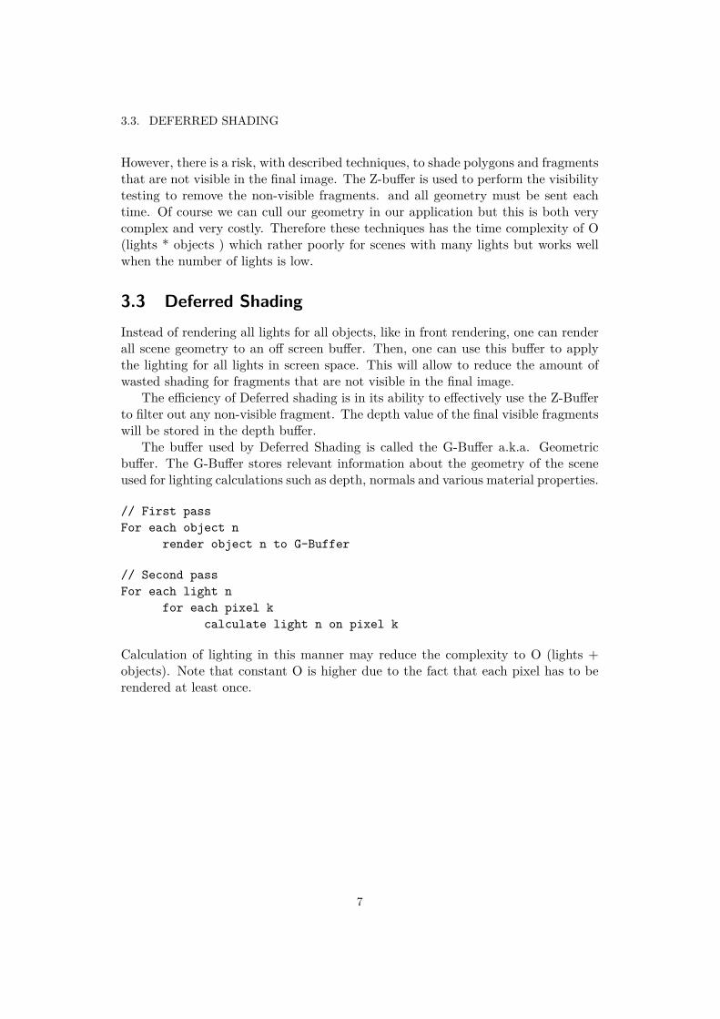
3.3 Deferred ShadingInstead of rendering all lights for all objects, like in front rendering, one can renderall scene geometry to an off screen buffer. Then, one can use this buffer to applythe lighting for all lights in screen space. This will allow to reduce the amount ofwasted shading for fragments that are not visible in the final image.
The efficiency of Deferred shading is in its ability to effectively use the Z-Bufferto filter out any non-visible fragment. The depth value of the final visible fragmentswill be stored in the depth buffer.
The buffer used by Deferred Shading is called the G-Buffer a.k.a. Geometricbuffer. The G-Buffer stores relevant information about the geometry of the sceneused for lighting calculations such as depth, normals and various material properties.
// First passFor each object n
render object n to G-Buffer
// Second passFor each light n
for each pixel kcalculate light n on pixel k
Calculation of lighting in this manner may reduce the complexity to O (lights +objects). Note that constant O is higher due to the fact that each pixel has to berendered at least once.
7
CHAPTER 3. ALGORITHM OVERVIEW
Figure 3.1: Geometry Stage: First geometry is sent to shader, then each materialproperty is saved into the G-Buffer. Lighting Stage: The G-Buffer is later boundas texture in order to calculate the final color. The color is saved in the P-Bufferand later copied to the framebuffer
8
Chapter 4
Implementation
The deferred shading and the front rendering pipeline have already been imple-mented in various games and applications, the game S.T.A.L.K.E.R being on ofthem. Compared to game as S.T.A.L.K.E.R. our implementation uses newer graph-ics API for later generations of graphic hardware. However the G-Buffer have beensimplified and only support one type of material which in this case is Blinn-Phong.Combining deferred shading with several types of materials as well as being com-patible with older graphics hardware was considered to be outside the scope of thiswork. Our implementation does not have any major optimization apart from usingnewer API. Many of the optimization that could be done are either too difficult ortake to long to be fitted inside this work. The whole application was built fromscratch using C++, nvidia CG and OpenGL.
4.1 Deferred shading with Front Rendering
The front render is used to process transparent objects and fits well into the de-ferred shading pipeline. It renders all opaque objects first with the deferred shaderand then renders the transparent objects on top using the front renderer. This isimportant as the depth buffer has to be filled with opaque objects first, to preventrendering of non-visible transparent objects. When the front renderer is performed,the final picture can be rendered to the frame buffer for display.
The implementation has the following rendering stages:
1. Render all opaque geometry to the G-Buffer2. Bind the G-Buffer as texture. For each light in the scene draw a full screen rect-angle and calculate lighting at each pixel using the data from the G-Buffer. Saveresult in the P-Buffer.3. Sort all transparent entities in back to front order.4. Render all transparent geometry using the front renderer. Blend the result to theP-Buffer using the depth buffer to filter out any non-visible transparent geometry.
9

CHAPTER 4. IMPLEMENTATION
5. Copy P-Buffer to frame buffer.
10

4.1. DEFERRED SHADING WITH FRONT RENDERING
Figure 4.1: After the final color from the Lighting Stage have been calculated, webind the G-Buffer depth buffer as texture for the front renderer. The depth buffer isused to filter out any non-visible transparent geometry. The front render its resulton top of the P-Buffer which is later copied to the framebuffer.
11

CHAPTER 4. IMPLEMENTATION
4.2 OpenGL ExtentionsIn order to simplify the deferred shading process, OpenGL FrameBufferObjects[16]are used for storing all information in the G-Buffer. This FrameBufferObject caneasily be switched with the default frame buffer, as well as able to be rebound astexture. When the buffers are bound as texture they can be used in the same way asnormal textures and can be used in lighting calculations. Note that FrameBufferOb-ject extension is only available on graphic hardware that supports OpenGL 4.1 anddoes requires shader model 5.0. In order to accelerate the drawing process OpenGLVertexBufferObjects[17] are used to store all relevant information regarding themodel attributes such as positions, normals, tangents and texture coordinates.
4.3 G-Buffer and P-BufferThe G-Buffer which holds the geometry information in the deferred shader is verysimple. It only holds the least amount of data to perform simple Blinn-Phong shad-ing.
The first buffer is the depth-buffer which uses 3 bytes. The remaining buffers
Table 4.1: Structure of the G-buffer.
R8 G8 B8 A8 TargetDepth24 - - Unused DepthDiffuse R8 Diffuse G8 Diffuse B8 Unused Color0Normal X8 Normal Y8 Normal Z8 Unused Color1Specular R8 Specular G8 Specular B8 Shinyness8 Color2
are for the diffuse color, normals and specular color and shininess. Note that allbuffers are in total of 4 bytes as required by the FrameBufferObject in order towork. The P-Buffer only hold R8 and G6 and B8 components which can later becopied to the framebuffer.
Table 4.2: Structure of the P-buffer.
R8 G8 B8 A8 TargetColor R8 Color G8 Color B8 Unused Color3
4.4 SortingFor sorting of transparent objects we use the built in stl::sort using Visual C++2010 with compiler version 16.00.40219.01. The average of a sort complexity is O(N
12

4.4. SORTING
log N), where N = last – first[18]. Transparent objects are sorted by the distancefrom the camera to the object itself. It is preferable to sort each polygon for eachentity in the scene in order to decrease the number of arte-facts. However, this mayresult in severe performance loss as each polygon would have to be translated eachframe and reloaded into the video memory. The sort by object was chosen in thiswork due to simplicity of implementation.
13


Chapter 5
Results
Efficiency of our deferred shading renderer was compared with Front renderer.
5.1 Test ModelA simple cube model was used to test our deferred shader. The model consists of 36vertices which make up for the total of 12 polygons. The rendering was performed100 times both for opaque and transparent geometry. We used VertexBufferObjectsto ensure the efficiency of time usage. The model properties including its textureare stored in video memory which improves the speed for loading these propertieswhen the GPU need to render the model.
15

CHAPTER 5. RESULTS
Figure 5.1: Diffuse color texture used for the test model
Figure 5.2: Normal map used for the test model
Table 5.1: Model properties.
Model CUBEVertices 36Polygons 12Data Vertex positions, normals, tangents and texture coordinatesSize in bytes 432 bytes
16

5.2. PERFORMANCE
5.2 PerformanceAll tests were performed on a Intel Core i7-2600 3.40 Ghz CPU using a RadeonHD 6570 GPU on Windows 7 64 bit system. Resolutions tested were 1280 x 800and 800 x 600, we choose these resolutions because we want to reflect resolution inmodern applications.
The tables 5.2, 5.3, 5.4, 5.5 were used to calculate the performance diagram5.3. The three columns to the right in each table represent the running time inapplication for each stage. Tests were done for 100 opaque (OP) CUBE modelsas well as 100 transparent (TR) CUBE models at both resolutions. In total therewere 4 tests and as we can confirm from figure [5.3] deferred shading scale betterfor many lights. Even at 50 lights the deferred shader preforms well in 800 x 600resolution. The front renderer does well with one light however as the number oflight increases it directly losses it’s ability to perform within the acceptable limitsof a real time application which is around at least 30 Fps. From table 1 to 4 wenote that for transparent objects the front renderer increases dramtically in runningtime as the number of light increases. This is most likely due to the front rendererdoing matrix calculations in application.
17

CHAPTER 5. RESULTS
Figure 5.3
Table 5.2: 100 Transparent objects at 1280 x 800 resolution
Number of lights FPS Deferred Shader ms Sorting ms Front Renderer ms1 55 0 1 210 6.18 0 1 1050 1.25 0 1 53100 0.6 0 1 88
Table 5.3: 100 Opaque objects at 1280 x 800 resultion
Number of lights FPS Deferred Shader ms Sorting ms Front Renderer ms1 190 2 0 010 91 2 0 050 24 2 0 0100 13 2 0 0
18

5.2. PERFORMANCE
Table 5.4: 100 Transparent objects at 800 x 600 resolution
Number of lights FPS Deferred Shader ms Sorting ms Front Renderer ms1 97 0 1 210 11 0 1 1050 2.23 0 1 45100 1.28 0 1 88
Table 5.5: 100 Opaque objects at 800 x 600 resolution
Number of lights FPS Deferred Shader ms Sorting ms Front Renderer ms1 250 2 0 010 156 2 0 050 50 2 0 0100 27 2 0 0
Figure 5.4: Buffer with diffuse color
19

CHAPTER 5. RESULTS
Figure 5.5: Buffer with normals
Figure 5.6: Buffer with specular color
20
5.2. PERFORMANCE
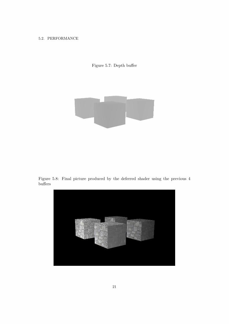
Figure 5.7: Depth buffer
Figure 5.8: Final picture produced by the deferred shader using the previous 4buffers
21

CHAPTER 5. RESULTS
Figure 5.9: Same pictures but rendered transparent with a front renderer
22

5.3. IMAGE QUALITY
5.3 Image QualityIf we take a look at a sample from the front renderer figure 5.10 we can clearly seethat the result from using multiple lights doesn’t look right. This has to do withthe order for which objects are rendered. We render for each light all objects in thescene, however what this does is that we do not render in back to front order. Ifwe had rendered all lights for each object and sorted all polygons, we could haveavoided these artifacts.
23

CHAPTER 5. RESULTS
Figure 5.10: Artifacts
24
Chapter 6
Conclusion and future work
As we increased the number of lights we effectively multiplied the number of objectsthat needs to be rendered. So given that we have 10 lights then each objects hasto be rendered and blended ten times. This is not true for the deferred shader asnoted by the results, for each added light we only draw one extra rectangle. Wedo lighting calculations at pixel level but the number extra calculations are far lessthan rendering all objects one more time.
We have shown that front rendering with alpha blending perform well enough tocomplement scenes rendered with deferred shading. We can use a low amount oftransparent objects or reduce the number of lights that effect the transparent ge-ometry. However in order to render transparent geometry in the same manner asdeferred shading in term of performance newer techniques needs to be used. Tech-niques that do not use sorting but are order-independent.
25

CHAPTER 6. CONCLUSION AND FUTURE WORK
6.1 References1. Thomas Porter, Tom Duff, Compositing Digital Images, SIGGRAPH, New
York, 1984, p253 - 259
2. Loren Carpenter, The A-buffer, an antialiased hidden surface method, SIG-GRAPH, New York, 1984, p103-108
3. Cass Everitt, Interactive order-independent transparency, NVIDIA white pa-per, 2001, p3
4. Baoquan Liu, Li-Yi Wei, Ying-Qing Xu, Multi-layered deepth peeling viafragment sort, Microsoft Research Asia, 2006, p1
5. Microsoft, Multiple Render Targets (Direct3D 9), Microsoft Dev Center, viewed2012.04.06
6. Louis Bavoil, Kevin Myers, Order Independent Tansparency with Dual DepthPeeling, Tech Rep, Nvidia, p3
7. Fang Liu et al, Effcient depth peeling via bucket sort, High PerformanceGraphics, New York, 2009
8. J.D. Mulder, F.C.A. Groen, J.J. Van Wijk, Pixel Masks for Screen-DoorTransparency, Proc. Conf. Visualization, 1998, pp. 351-358
9. Eric Enderton, Erik Sintorn, Peter Shirley, David Leubke, Stochastic trans-parency, 2010 ACM SIGGRAPH symposium on Interactive 3D Graphics andGames, New York, 2010, p1
10. Marco Salvi, Jeffersson Montgomery, Aaron Lefohn, Adaptive Transparency,HPG ’11 Proceedings of the ACM SIGGRAPH Symposium on High Perfor-mance Graphics, New York, 2011, p1
11. Takafumi Saito, Tokiichiro Takahashi, Compreshensible rendering of 3-D shapes,SIGGRAPH ’90 Proceedings of the 17th annual conference on Computergraphics and interactive techniques, 1990, New York, 197-206
12. Scott Kircher, Alan Lawrance, Inferred lighting: fast dynamic lighting andshadows for opaque and translucent objects, Sandbox, Proceedings of the2009 ACM SIGGRAPH Symposium on Video Games, 2009, New York, p39 -45
13. Shishkovtsov, Deferred shading in s.t.a.l.k.e.r, In GPU Gems 2, Addison-Wesley, 2005, ch. 9, 143-166
14. Koonce, Rusty, Deferred Shading in Tabula Rasa, Hubert Nguyen GPU Gems3, Addison-Wesley, 2007, p429-457
26

6.1. REFERENCES
15. James F. Blinn, Models of light reflection for computer synthesized pictures,SIGGRAPH ’77 Proceedings of the 4th annual conference on Computer graph-ics and interactive techniquesACM, New York, 1977. p1
16. FrameBuffer Object, OpenGL, viewed 2012.04.12
17. VertexBuffer Object, OpenGL, viewed 2012.04.12
18. MSDN , Visual C++ Standard Library <algorithm> sort, Microsoft, viewed2012.04.11, cited on page 1
27

CHAPTER 6. CONCLUSION AND FUTURE WORK
6.2 Statement of collaborationThe content of this document was written and produced by Christian Magnerfelt.All related software to this document was developed by Christian Magnerfelt.
28


www.kth.se


![[Ndc11 박민근] deferred shading](https://img.dokumen.tips/doc/110x75/55624416d8b42a52078b5cf0/ndc11-deferred-shading.jpg)