Embed Size (px)
Citation preview
REV. 00
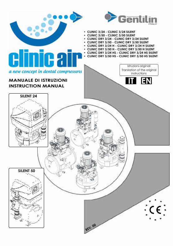
SILENT 24
SILENT 50
• CLINIC 3/24 - CLINIC 3/24 SILENT• CLINIC 3/50 - CLINIC 3/50 SILENT• CLINIC DRY 3/24 - CLINIC DRY 3/24 SILENT• CLINIC DRY 3/50 - CLINIC DRY 3/50 SILENT• CLINIC DRY 3/24 H - CLINIC DRY 3/24 H SILENT• CLINIC DRY 3/50 H - CLINIC DRY 3/50 H SILENT• CLINIC DRY 3/24 HS - CLINIC DRY 3/24 HS SILENT• CLINIC DRY 3/50 HS - CLINIC DRY 3/50 HS SILENT
ITMANUALE DI ISTRUZIONIINSTRUCTION MANUAL
EN
Istruzioni originaliTranslation of the original
instructions


3
IT
MANUALE ISTRUZIONI Serie Clinic 3
REV. 00
5 PRESENTAZIONE
6 DICHIARAZIONI E COLLAUDO 6 Dichiarazione di consegna manuale di
istruzioni 7 Certificato di collaudo e messa in servizio
8 DICHIARAZIONI E MARCATURA CE 8 Dichiarazione CE di conformità 9 Marcatura CE e dati tecnici
10 GENERALITÀ 10 Importanza del manuale 11 Note di consultazione 12 Stato “macchina spenta” 12 Operatori autorizzati 17 Abbreviazioni 18 Diritti riservati18 Garanzia
20 DESCRIZIONE TECNICA20 Designazione della macchina21 Denominazione dei modelli22 Denominazione dei componenti26 Dimensioni della macchina27 Dati tecnici27 Dati macchina28 Uso previsto della macchina29 Fonte energetica di alimentazione30 Prodotti utilizzati per il funzionamento30 Fasi di funzionamento30 Uso scorretto ragionevolmente
prevedibile
32 TRASPORTO E MOVIMENTAZIONE32 Trasporto della macchina32 Imballo33 Movimentazione dell’imballo con
carrello elevatore o transpallet33 Sballaggio34 Movimentazione manuale della macchina35 Posizionamento della macchina
36 INSTALLAZIONE36 Avvertenze generali36 Collegamento pneumatico37 Collegamento elettrico
Pag.
INSTRUCTION MANUAL
EN
5 INTRODUCTION
6 STATEMENTS AND TESTING 6 Statement of delivery of the instruction
manual 7 Testing and commissioning certificate
8 STATEMENT AND CE MARk 8 CE declaration of conformity 9 Statement and CE mark
10 GENERALI 10 Importance of the manual 11 Consultation notes 12 State “machine off” 12 Authorized operators 17 Abbreviations 18 All rights reserved18 Warranty
20 TECHNICAL DESCRIPTION20 Designation of the machine21 Name of models22 Names of parts26 Dimensions of the machine27 echnical data27 Machine data28 Intended use of the machine29 Source of energy supply30 Products used for the operation30 Phases of operation30 Reasonably foreseeable misuse
32 TRANSPORTATION AND HANDLING32 Transportation of the machine32 Packaging33 Handling of packaging with a forklift
or transpallet33 Unpacking34 Manual handling of the machine35 Positioning of the machine
36 INSTALLATION36 General warnings36 Pneumatic connection37 Electric connection
Page
4
IT
MANUALE ISTRUZIONI Serie Clinic 3
REV. 00
Pag.
39 SICUREZZA39 Dispositivi di sicurezza44 Dispositivi di protezione individuale (DPI)44 Rischi residui 46 Segnaletica di sicurezza
47 USO E FUNZIONAMENTO47 Posti occupati dagli operatori autorizzati48 Pressostato52 Controlli prima dell’accensione53 Accensione della macchina54 Regolazione della pressione in uscita54 Reset del termico ripristinabile55 Spegnimento della macchina55 Arresto di emergenza56 Accensione dopo un arresto di emergenza56 Intervento valvola di sicurezza
57 ANOMALIE - CAUSE - RIMEDI
60 MANUTENZIONE66 Manutenzione straordinaria
66 MESSA FUORI SERVIZIO66 Magazzinaggio67 Demolizione
67 RICAMBI
67 ALLEGATI
INSTRUCTION MANUAL
ENPage
39 SAFETY39 Safety devices44 Personal protective equipment (PPD)44 Residual risks46 Safety signs
47 USE AND OPERATION 47 Places occupied by authorized operators48 Control devices52 Prior to ignition53 Turning on the machine54 Adjusting the outlet pressure54 Resettable thermal55 Turning off the machine55 Emergency stop56 Activation after an emergency stop56 Intervention of the safety valve
57 TROUBLESHOOTING
60 MAINTENANCE66 Extraordinary maintenance
66 DECOMMISSIONING66 Storage67 Demolition
67 SPARE PARTS
67 ATTACHMENTS
5
IT
MANUALE ISTRUZIONI Serie Clinic 3
REV. 00
PRESENTAZIONEGentile cliente, vogliamo, innanzi tutto, ringraziarLa per la fiducia accordataci nell’acquisto del Suo nuovo compressore. Siamo certi che le Sue aspettative saran-no soddisfatte, visto il livello tecnologico raggiunto dai nostri prodotti grazie ad un costante impegno che, quotidianamente, ci stimola a crescere, per saper affrontare con professionalità le continue trasforma-zioni tecnologiche, produttive e commer-ciali. Sicuri di poter incontrare anche ogni Sua futura esigenza lavorativa, siamo lieti di rimanere a disposizione ed offrire tutta la nostra esperienza e conoscenza per la mi-gliore soluzione per ogni Vostro quesito.
INFORMAZIONE AL CLIENTEDOCUMENTO PAGINA DA FARE
DICHIARAZIONE DI CONSEGNA MANUALE DI ISTRUZIONI 6
Gli operatori autorizzati devono compilare e firmare per consegna e presa visione del manuale di istruzioni.
CERTIFICATO DI COLLAUDOE MESSA IN SERVIZIO 7
Consegnare al tecnico collaudatore delFabbricante o Rivenditore Autorizzato la copia di pagina 7 compilata in tutte le sue parti.
REGISTRAZIONE PRODOTTO PER VALIDAZIONE GARANZIA 18 Vedi paragrafo “GARANzIA” - Punto 2)
Pagina 18.
INSTRUCTION MANUAL
ENINTRODUCTION
Dear Customer, first of all, we wish to thank you for the confidence you gave us by pur-chasing your new “COMPRESSOR”.We are sure that your expectations will be met, given the level of technology achie-ved by our products with a continued com-mitment on a daily basis, which encourages us to grow, to know how to deal with the constant changes in technology expertise, manufacturing and sales.We feel sure we can meet your future requi-rements, therefore, feel free to contact us. We will be happy to offer you all our expe-rience and knowledge to answer any que-stion you may have.
INFORMATION TO THE CUSTOMERDOCUMENT PAGE TO DO
STATEMENT OF DELIVERY OF THE INSTRUCTION MANUAL 6
The authorised operators must complete and sign to confirm the delivery and rea-ding of the instruction manual.
TESTING AND COMMISSIONING CERTIFICATE 7
Give to the test technician of the Manufac-turer or to the Authorized Dealer a copy of page 7 completed in all its parts.
PRODUCT REGISTRATION FOR WARRANTY VALIDATION 18 See paragraph “WARRANTY” - Section 2)
Page 18.

6
IT
MANUALE ISTRUZIONI Serie Clinic 3
REV. 00
Prima di compilare la tabella si consi-glia di fotocopiarla per futuri riferimen-ti.
DICHIARAZIONI E COLLAUDODICHIARAZIONE DI CONSEGNA MANUALE DI ISTRUZIONIIl datore di lavoro, conformemente a quan-to prescritto dalla legislazione vigente in materia di sicurezza e salute dei lavoratori sul luogo di lavoro, dichiara di avere con-segnato agli operatori autorizzati il presente manuale per una corretta informazione e formazione sull’utilizzo e la manutenzione della macchina.
INSTRUCTION MANUAL
ENSTATEMENTS AND TESTING
STATEMENT OF DELIVERY OF THEINSTRUCTION MANUALThe employer, to the extent required by ap-plicable law on safety and health of wor-kers at work, hereby declares it has delive-red to the authorized operators this manual for the correct information and training on use and maintenance of the machine
OPERATORI AUTORIZZATIAUTHORIZED OPERATORS
DATADATE
FIRMA PER RICEVUTASIGNATURE FOR RECEIPT
Sig./Mr.____________________________ __________ _________________________________
Sig./Mr.____________________________ __________ _________________________________
Sig./Mr.____________________________ __________ _________________________________
Sig./Mr.____________________________ __________ _________________________________
Sig./Mr.____________________________ __________ _________________________________
Sig./Mr.____________________________ __________ _________________________________
Sig./Mr.____________________________ __________ _________________________________
Sig./Mr.____________________________ __________ _________________________________
Sig./Mr.____________________________ __________ _________________________________
Sig./Mr.____________________________ __________ _________________________________
Beforefillinginthetable,photocopyitfor future reference.

7
IT
MANUALE ISTRUZIONI Serie Clinic 3
REV. 00
INSTRUCTION MANUAL
EN
CERTIFICATO DI COLLAUDO E MESSA IN SERVIZIOTESTING AND COMMISSIONING CERTIFICATE
DATA/DATE _________________
Denominazione: compressoreDesignation: compressor
Nome:_________________________Name:
Modello:________________________________Model:
Via:____________________________Street:
Numero di serie:__________________________Serial No:
Città:___________________________City:
Anno di costruzione:Manufacture year:
Nazione:________________________State:
Si certifica che la macchina in oggetto è stata collaudata dal:This is to certify that the machine in question was tested by:Tecnico collaudatore del Fabbricante o Rivenditore Autorizzato:Test technician of the manufacturer or authorized dealer:
Sig./ Mr:________________________________________________________________________Alla presenza dell’operatore addetto:At the presence of the entrusted operator:
Sig./ Mr:________________________________________________________________________
Alla presenza del Responsabile del Servizio di Prevenzione e Protezione (R.S.P.P.):At the presence of the entrusted operator and Safety Representative:
Sig./ Mr:________________________________________________________________________
Verifica della corretta installazione della macchina.Check for proper installation of the machine.
Verifica della corretta impostazione di tutti i parametri di lavoro.Verification of the correct setting of all the working parameters.
Verifica del corretto funzionamento edintervento di tutti i dispositivi di sicurezza.Verification of correct operation and intervention of all the safety devices.
Messa in servizio ed esecuzione di un ciclo di lavoro.Commissioning and perfor-mance of a work cycle.Eventuale ottimizzazione dei parametri di lavoro.Possible optimization of the working parameters.Arresto della macchina.Machine stop.Consegna manuale di istruzioni.Delivery of the instruction manual.
FIRMA / SIGNATURETecnico collaudatore del Fabbricante o Rivenditore AutorizzatoTest Technician of the Manufacturer or Authorized Dealer
Responsabile del Servizio di Pre-venzione e Protezione (R.S.P.P.)Safety Representative

8
IT
MANUALE ISTRUZIONI Serie Clinic 3
REV. 00
INSTRUCTION MANUAL
ENDICHIARAZIONE CE DI CONFORMITÀEC DECLARATION OF CONFORMITY
Gentilin S.r.l. - Via delle Tezze, 20/22 36070 Trissino (VI) - Italy - P.IVA/VAT N.: 01262520248
Dichiara che le seguenti macchine / Declares that the following machine:
CLINIC 3/24 - CLINIC 3/24 SILENT - CLINIC 3/50 - CLINIC 3/50 SILENTCLINIC DRY 3/24 - CLINIC DRY 3/24 SILENT - CLINIC DRY 3/50 - CLINIC DRY 3/50 SILENT
CLINIC DRY 3/24 H - CLINIC DRY 3/24 H SILENT - CLINIC DRY 3/50 H - CLINIC DRY 3/50 H SILENTCLINIC DRY 3/24 HS - CLINIC DRY 3/24 HS SILENT - CLINIC DRY 3/50 HS - CLINIC DRY 3/50 HS SILENT
Macchina / Machine: Compressore volumetrico per aria / Air volumetric compressor
Matricola / Serial Number: ___________________________________________
Sono conformi alle disposizioni delle seguenti direttive / Complies with the following directives:2006/42/CE Direttiva del Parlamento Europeo e del Consiglio del 17 maggio 2006, relativa alle macchi-ne e che modifica la direttiva 95/16/CE (rifusione)2006/42/EC Directive of the European Parliament and the Council of 17 May 2006 on machinery and amending Directive 95/16/EC (recast)
2004/108/CE Direttiva del Parlamento Europeo e del Consiglio del 15 dicembre 2004, concernente il ravvicinamento delle legislazioni degli Stati Membrirelative alla compatibilità elettromagnetica e che abroga da Direttiva 89/336/CEE97/23/CE (Art. 3.3)2004/108/EC Directive of the European Parliament and of the Council of 15 December 2004, on the ap-proximation of the laws of the Member States relating to electromagnetic compatibility and repealing Directive 89/336/EEC
Direttiva 2006/95/CE del Parlamento Europeo e del Consiglio, del 12 Dicembre 2006Directive 2006/95/EC of the European Parlament and Council, of December 12, 2006
Persona autorizzata a costituire il Fascicolo Tecnico/ Person authorized to prepare the Technical Dossier:Gentilin Giuseppe, in qualità di Responsabile Tecnico / in quality of Technical Manager
Luogo/ Place: ViadelleTezze,20/22-36070Trissino(VI)ITALY Data/Date: _________________________
Timbro / Stamp:Il Legale Rappresentante / Legal Representative(Gentilin Giampaolo)
Firma / Signature:

9
IT
MANUALE ISTRUZIONI Serie Clinic 3
REV. 00
DICHIARAZIONE E MARCATURA CE
MARCATURA CE E DATI TECNICILa marcatura CE (Fig.1) attesta la confor-mità della macchina ai requisiti essenziali di sicurezza e di salute previsti dalle Direttive Europee riportate nella dichiarazione CE di conformità.L’etichetta è realizzata con stampa in bian-co e nero su PVC polimerico adesivo ed ha le seguenti dimensioni: L = 70 mm - H = 55 mm.È applicata esternamente su un lato del-la macchina indicato in Fig. 1 e riporta, in modo leggibile, i seguenti dati:• IL LOGO, IL NOME E L’INDIRIZZO DEL
FABBRICANTE• LA MARCATURA CE• LA DESIGNAzIONE DELLA MACCHINA
(tipo/modello)• L’ANNO DI COSTRUZIONE• IL NUMERO DI SERIE• IL VALORE DI S1• LA PRESSIONE MAX. DI ESERCIZIO (bar)• LA TENSIONE (V/Hz/A)• LA VELOCITÀ DI ROTAZIONE ALBERO (rpm)• LA POTENZA NOMINALE (kW)• IL PESO (kg)
Fig. 1
INSTRUCTION MANUAL
ENSTATEMENT AND
CE MARkMARkING AND TECHNICAL DATAThe CE marking (Fig.1) of the machine indi-cates compliance with the essential occu-pational health and safety rules set forth by the European Directives listed in the Decla-ration of CE Conformity.The label is black and white printed on adhesive polymeric PVC and has the fol-lowing dimensions: L = 70 mm - H = 55 mm.It is applied externally on one side of the machine indicated in Fig. 1 and states the following data, in a legible manner:• LOGO, NAME AND ADDRESS OF
MANUFACTURER• CE MARKING• DESIGNATION OF THE MACHINE
(type / model)• YEAR OF MANUFACTURE• SERIAL NUMBER• S1 VALUE• MAX. WORKING PRESSURE (bar)• VOLTAGE (V / Hz / A)• SHAFT ROTATION SPEED (rpm)• RATED POWER (kW)• WEIGHT (kg)
Mod. 24 litri/liters Mod. 50 litri/liters
10
IT
MANUALE ISTRUZIONI Serie Clinic 3
REV. 00
GENERALITÀIMPORTANZA DEL MANUALE
Primadiutilizzarelamacchinainog-gettoèobbligatoriocheglioperato-ri autorizzati leggano e comprenda-
no,intuttelesueparti,ilpresentemanuale.
Il presente manuale di istruzioni è stato re-datto secondo le indicazioni previste dalle Direttive Europee, al fine di garantire una facile e corretta comprensione degli argo-menti trattati da parte degli operatori auto-rizzati all’utilizzo e alla manutenzione della macchina in oggetto. Se, nonostante l’at-tenzione prestata in fase di redazione da parte del fabbricante, gli operatori suddetti riscontrassero qualche incomprensione nel-la lettura, sono pregati, onde evitare errate interpretazioni personali che compromet-tano la sicurezza, di richiedere tempestiva-mente al fabbricante le corrette spiegazio-ni ed informazioni.Prima di utilizzare la macchina in oggetto, gli operatori autorizzati devono obbligato-riamente leggere e comprendere in tutte le sue parti il presente manuale di istruzioni ed attenersi rigorosamente alle norme ivi de-scritte, al fine di garantire la propria e l’al-trui sicurezza, ottenere le migliori prestazioni della macchina ed assicurare, a tutti i suoi componenti, la massima efficienza e dura-ta. Il presente manuale deve, in qualsiasi momento, essere a disposizione degli ope-ratori autorizzati e trovarsi, ben custodito e conservato, sempre vicino alla macchina.
Il presente manuale deve sempre essere a disposizione degli operatori autorizzati e trovarsi nelle vicinanze
dellamacchinabencustoditoeconserva-to. Il presente manuale deve essere obbli-gatoriamente consegnato assieme alla macchinaqualoravengacedutaadaltroutilizzatore.
INSTRUCTION MANUAL
ENGENERAL
IMPORTANCE OF THE MANUAL
Before using the machine in que-stion, the authorized operators areobliged to readand thoroughlyun-
derstandthismanualinallitsparts.
This instruction manual has been prepared in accordance with the directions provided by the European Directives in order to en-sure an easy and correct understanding of the topics covered by the authorized ope-rators operating and maintaining the ma-chine in question.If, despite the attention being paid by the manufacturer while drafting this document, such operators should not fully understand this text while reading, they are requested to ask the manufacturer for the correct explanations and information in order to avoid incorrect personal interpretations that may jeopardize safety.Before using the involved machine, the authorized operators are obliged to read and understand all parts of this manual and adhere strictly to the rules herein described in order to assure their own and others’ sa-fety, the best performance of the machine and ensure the maximum efficiency and durability of all its components.This manual shall be available at any time for the authorized operators and shall be well protected and preserved, always clo-se to the machine.
Thismanualshouldalwaysbeavai-lable for authorized operators andlocatedinthevicinityofthemachine
wellprotectedandpreserved.Thismanualmust compulsorily be delive-red together with the machine when it istransferredtoanotheruser.
11
IT
MANUALE ISTRUZIONI Serie Clinic 3
REV. 00
Il fabbricante declina ogni responsabilità perdanniapersone,animalie/ocosecau-sati dall’inosservanza delle norme e delle avvertenze descritte nel presente manuale. Ilpresentemanualerispecchialostatodel-la tecnica al momento della commercializ-zazionedellamacchinaenonpuòessereconsiderato inadeguato solo perché, inbaseanuoveesperienze,puòesseresuc-cessivamente aggiornato.In caso di smarrimento o deterioramento del manuale richiederne copia al fabbri-cante,specificandoidatidiidentificazionedeldocumento:codice,emissionee revi-sione(vediCopertina).
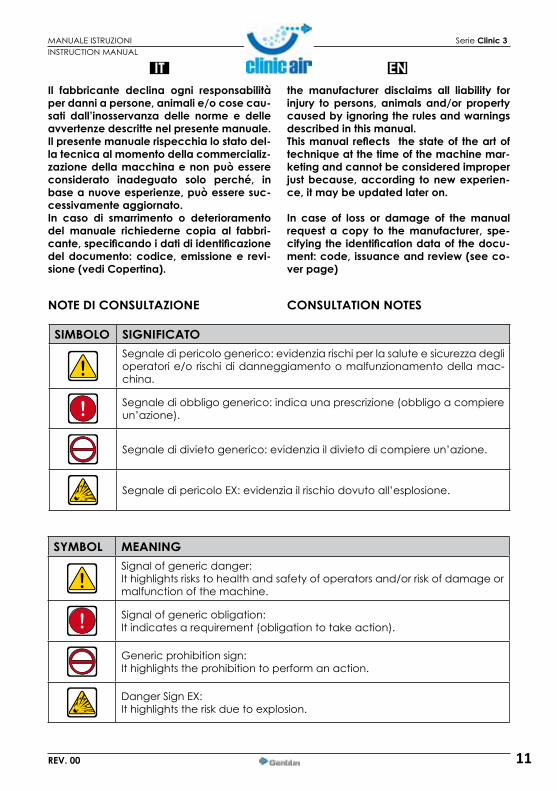
SIMBOLO SIGNIFICATOSegnale di pericolo generico: evidenzia rischi per la salute e sicurezza degli operatori e/o rischi di danneggiamento o malfunzionamento della mac-china.
Segnale di obbligo generico: indica una prescrizione (obbligo a compiere un’azione).
Segnale di divieto generico: evidenzia il divieto di compiere un’azione.
Segnale di pericolo EX: evidenzia il rischio dovuto all’esplosione.
NOTE DI CONSULTAZIONE
INSTRUCTION MANUAL
ENthe manufacturer disclaims all liability forinjury topersons, animals and/orpropertycausedbyignoringtherulesandwarningsdescribedinthismanual.Thismanual reflects thestateof theartoftechniqueatthetimeofthemachinemar-keting and cannot be considered improper justbecause,according tonewexperien-ce,itmaybeupdatedlateron.
In case of loss or damage of themanualrequest a copy to themanufacturer, spe-cifyingtheidentificationdataofthedocu-ment:code,issuanceandreview(seeco-verpage)
SYMBOL MEANINGSignal of generic danger:It highlights risks to health and safety of operators and/or risk of damage or malfunction of the machine.
Signal of generic obligation:It indicates a requirement (obligation to take action).
Generic prohibition sign:It highlights the prohibition to perform an action.
Danger Sign EX:It highlights the risk due to explosion.
CONSULTATION NOTES
12
IT
MANUALE ISTRUZIONI Serie Clinic 3
REV. 00
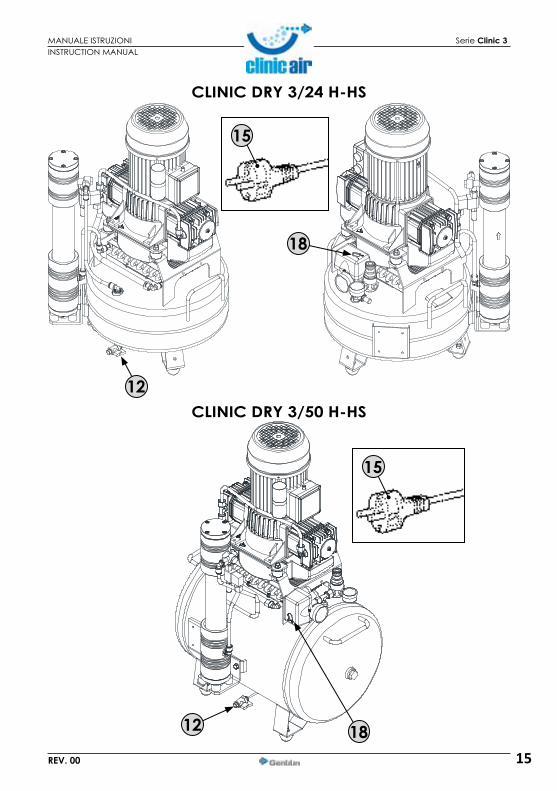
STATO “MACCHINA SPENTA”Prima di eseguire qualsiasi tipo di in-tervento manutentivo e/o di regola-zione sulla macchina, è obbligatorio sezionare l’alimentazione elettrica assicurandosi che l’interruttore (18)sia nella pos. “OFF (0)”, che la spina
del cavo di alimentazione elettrica (15) sia disinserita dalla presa e posizionata vicino alla macchina e che il serbatoio sia stato scaricato dall’aria compressa residua aprendo la valvola di scarico condensa (12) (vedi altri modelli su pagine successive).
OPERATORI AUTORIZZATIGLI OPERATORI AUTORIZZATI DEVO-NO ESEGUIRE SULLA MACCHINA ESCLUSIVAMENTE GLI INTERVENTI DI
LORO SPECIFICA COMPETENZA. GLI OPERA-TORIAUTORIZZATI,PRIMADIESEGUIREQUAL-SIASIINTERVENTOSULLAMACCHINA,DEVO-NO ASSICURARSI DI ESSERE IN POSSESSO DELLE PIENE FACOLTÀ PSICO-FISICHE TALI DA GARANTIRE SEMPRE IL RISPETTO DELLE CONDIZIONI DI SICUREZZA.Questomanualetecnicoèdestinato,esclu-sivamente,aglioperatoriautorizzatiall’usoe alla manutenzione della macchina inbaseallespecifichecompetenzetecnico-professionalirichiesteperiltipodiinterven-to. I simboli di seguito indicati sono disposti all’iniziodiuncapitoloe/odiunparagrafo,adindicarequalesial’operatoreinteressa-to all’argomento trattato.
OPERATORE ADDETTOÈ un operatore professionalmente addestrato, abilitato ad eseguire esclusivamente l’accensione, l’utiliz-
zo, l’attrezzaggio, la messa a punto (obbli-gatoriamente con le protezioni abilitate e la macchina spenta) e lo spegnimento del-la macchina nel rispetto assoluto delle istru-zioni riportate nel presente manuale, dota-to dei dispositivi di protezione individuale (DPI) previsti e occupante i posti descritti (vedi relativo paragrafo).
INSTRUCTION MANUAL
ENSTATE “MACHINE OFF”
Before performing any type of main-tenance and/or setting on the ma-chine, disconnect the power supply ensuring that the switch (18) is in po-sition “OFF (0)”, the plug of the po-wer cable (15) is unplugged and pla-
ced near the machine and the tank has been drained from residual compressed air by opening the drain valve (12) (see other models on the following pages).
AUTHORIZED OPERATORSTHE OPERATORS ARE AUTHORIZED TO MAkE ON THE MACHINE ONLY SPECI-FIC ACTIONS OF THEIR COMPETENCE.
THE AUTHORIZED OPERATORS, BEFORE PER-FORMING ANY WORk ON THE MACHINE MUST BE SURE TO BE IN POSSESSION OF FULL PSYCHO-PHYSICAL CAPACITIES, SUCH ASTO ENSURE COMPLIANCE WITH THE SAFETY CONDITIONS.This technical manual is intended exclu-sively for Authorized Operators to the useandmaintenance ofmachines accordingtospecifictechnicalandprofessionalskillsrequired for the type of intervention. Thesymbols below are arranged at the be-ginningofachapterand/orparagraph,toindicate which is the operator concernedwiththesubjectmatter.
OPERATOR IN CHARGEIt is a professionally trained operator, authorized to perform only the igni-tion, use, setup, tuning (with the
mandatory protection enabled and the machine turned off) and the turning off of the machine and in total respect of the in-structions in this manual, equipped with personalprotectiveequipment(PPD) speci-fied and occupying the places (see rela-ted paragraph).

13
MANUALE ISTRUZIONI Serie Clinic 3
REV. 00
CLINIC 3/24
1518
12
18
12
15
CLINIC 3/50
INSTRUCTION MANUAL

14
MANUALE ISTRUZIONI Serie Clinic 3
REV. 00
CLINIC DRY 3/24
CLINIC DRY 3/50
15
15
12
18
12
18
INSTRUCTION MANUAL
15
MANUALE ISTRUZIONI Serie Clinic 3
REV. 00
CLINIC DRY 3/24 H-HS
CLINIC DRY 3/50 H-HS
15
15
12
18
12 18
INSTRUCTION MANUAL

16
IT
MANUALE ISTRUZIONI Serie Clinic 3
REV. 00
OPERATORE ADDETTO ALLA MOVIMENTAZIONE
È un operatore professionalmente addestrato, che abbia compiuto il 18° anno di età, nel rispetto della le-
gislazione vigente nel paese di utilizzazione, abilitato alla conduzione di carrelli elevato-ri, carri ponti o gru, per effettuare in sicurez-za il trasporto, la movimentazione e lo sbal-laggio della macchina e/o di parti di essa,dotato dei dispositivi di protezione in-dividuale(DPI)previsti e occupante i posti descritti (vedi relativo paragrafo).
MANUTENTORE MECCANICOIDRAULICO/PNEUMATICO
È un tecnico qualificato, abilitato ad eseguire esclusivamente interventi sugli organi meccanici/idraulici/
pneumatici per effettuare regolazioni, ma-nutenzioni e/o riparazioni anche con le pro-tezioni disabilitate (su consenso del respon-sabile del servizio di prevenzione e protezione) nel rispetto assoluto delle istru-zioni riportate nel presente manuale o altro documento specifico fornito esclusivamen-te dal fabbricante, dotato dei dispositivi di protezioneindividuale(DPI) previsti e occu-pante i posti descritti (vedi relativo para-grafo).
MANUTENTORE ELETTRICO
È un tecnico qualificato (elettricista in possesso dei requisiti tecnico pro-fessionali richiesti dalle normative vi-
genti), abilitato ad eseguire esclusivamen-te interventi su dispositivi elettrici per effettuare regolazioni, manutenzioni e/o ri-parazioni anche in presenza di tensione elettrica e con le protezioni disabilitate (su consenso del responsabile del servizio di prevenzione e protezione), dotato dei di-spositividiprotezioneindividuale(DPI)pre-visti e occupante i posti descritti (vedi relati-vo paragrafo).
INSTRUCTION MANUAL
ENOPERATOR IN CHARGEFOR HANDLING
It is a professionally trained operator, who has completed 18 years of age, in accordance with the law in the
country of use, enabled to the conduct of forklifts, cranes or bridges wagons, to make safe transport, handling and unpacking the machine and/or parts of it, with the perso-nal protective equipment (PPD) specified and occupying the places described (see related paragraph).
MECHANICAL/HYDRAULIC/PNEUMA-TIC MAINTENANCE TECHNICIAN
It is a qualified technician, authori-zed to perform actions only on the mechanical/hydraulic/pneumatic
parts to make adjustments, and mainte-nance and/or repairs, even with the pro-tections disabled (upon consent of the Su-pervisor) in strict compliance with the instructions in this manual or other docu-ment specifically provided exclusively by the manufacturer, equipped with personal protective equipment (PPD) specified and occupying the places described (see rela-ted paragraph).
ELECTRICAL MAINTENANCE TECHNICIAN
It is a qualified technician (an electri-cian in possession of technical and professional qualifications required
by the regulations), authorized to perform only work on electrical equipment to make adjustments, and maintenance and/or re-pairs, even in the presence of voltage and with the protections disabled (upon con-sent of the Supervisor), equippedwithper-sonal protection devices (PPD) envisioned and occupying the positions described (see related paragraph).

17
IT
MANUALE ISTRUZIONI Serie Clinic 3
REV. 00
RESPONSABILE DEL SERVIZIO DI PREVENZIONEEPROTEZIONE(R.S.P.P.)
È un tecnico qualificato designato dal Cliente in possesso dei requisiti tecnico professionali richiesti dalle
normative vigenti in materia di sicurezza e di salute dei lavoratori sui luoghi di lavoro.
TECNICO DEL FABBRICANTEÈ un tecnico qualificato messo a di-sposizione dal fabbricante e/o dal rivenditore autorizzato per effettuare
l’assistenza tecnica richiesta, interventi di manutenzione ordinaria e straordinaria e/o operazioni non riportate nel presente ma-nuale che richiedano una conoscenza spe-cifica della macchina, dotato dei dispositi-vi di protezione individuale (DPI) previsti (vedi relativo paragrafo).
ABBREVIAZIONIElenchiamo alcune abbreviazioni usate nel manuale.• ca. = Circa • min = Minuti• cap. = Capitolo • N. = Numero• DPI = Dispositivi di Protezione Individuale • pag. = Pagina• DX = Destro/a • par. = Paragrafo• h = Ore • Pos. = Posizione• EN = European Norm • Rif. = Riferimento• Es. = Esempio • s = Secondi• FIG. = Figura/e • SX = Sinistro/a• max. = Massimo/a • TAB. = Tabella• min. = Minimo/a • v. = Vedi
INSTRUCTION MANUAL
ENSAFETY REPRESENTATIVE
It is a qualified engineer appointed by the customer in possession of technical and professional qualifica-
tions required by the regulations on safety and health of workers in the workplace.
MANUFACTURER’S TECHNICIANIt is a qualified technician made available by the manufacturer and/or authorized dealer to perform the
required technical assistance, routine work and extraordinary maintenance and/or operations not mentioned in this manual that require specific knowledge of the ma-chine, equipped with personal protective equipment(PPD)specified (see related pa-ragraph).
ABBREVIATIONSLists some abbreviations used in this book.
• ca. = About• cap. = Chapter• PPE = Personal protective equipment• R = Right• h = Hours• EN = European Norm• Es. = Example• Fig. = Figure• max. = Maximum• min. = Minimum• min = Minutes• N. = Number• page = Page• par. = Paragraph• Pos. = Position• Rif. = Reference• sec. = Seconds• L = Left• TAB. = Table• see = SEE

18
IT
MANUALE ISTRUZIONI Serie Clinic 3
REV. 00
DIRITTI RISERVATII diritti riservati riguardanti questo manuale di istruzioni rimangono in possesso del Fab-bricante. Ogni informazione (testo, disegni, schemi, ecc...) qui riportata è riservata. Nessuna parte del presente manuale può essere riprodotta e diffusa (completamente o parzialmente) con un qualsiasi mezzo di riproduzione, (fotocopie, microfilm o altro) senza l’autorizzazione scritta da parte del Fabbricante. Tutti i marchi citati apparten-gono ai rispettivi proprietari.
GARANZIA1) DICHIARAzIONE DI GARANzIA: il Fabbri-
cante si impegna nei confronti dell’ac-quirente di sostituire, riparare o interve-nire altrimenti sulla macchina,qualora essa presenti dei difetti di conformità che ne compromettano il corretto uso e funzionamento,esclusivamente se tali difetti sono riconducibili alla effettiva responsabilità del Fabbricante. Il Fabbri-cante si riserverà il diritto di adottare la soluzione migliore per ripristinare la con-formità in un lasso di tempo ragionevole.
2) TERMINI: l’apparecchio è in garanzia per 3(tre)annidalla data di installazione, a condizione ce sia effettuata la registra-zione tramite apposito modulo “REGISTRA PRODOTTO” sul sito web www.clinicair.it, entro una settimana dalla installazione all’utilizzatore finale (vedi card garanzia allegata al presente manuale).
3) DECADENzA: la garanzia decade nel caso in cui l’acquirente utilizzi la macchina in modo improprio e/o non conforme a quanto ripor-tato nel presente “Manuale di Istruzioni” forni-to dal Fabbricante, o nel caso in cui il difetto di conformità sia stato causato da imperizia dell’acquirente o da un caso fortuito. Inoltre la garanzia decade qualora la macchina e/o gli impianti vengano manomessi per interventi di qualsiasi natura effettuati da persone non idonee e quindi non autorizzate dal Fabbri-cante.
INSTRUCTION MANUAL
ENALL RIGHTS RESERVEDThe reserved rights related to this instruction manual are in possession of the manufac-turer.All information (text, drawings, diagrams, etc.) given here is confidential. No part of this manual may be reproduced and distri-buted (in whole or in part) by any means of reproduction (photocopy, microfilm or otherwise) without the written consent of the Manufacturer. All trademarks are pro-perty of their respective owners.
WARRANTY1) STATEMENT OF WARRANTY: The Manu-
facturer undertakes with the buyer to replace, repair, or otherwise act on the machine, if it is found any lack of con-formity which affects the proper use and operation, only if such defects are attributable to the actual liability of the Manufacturer. The Manufacturer reserves the right to adopt the best solution to re-store compliance in a reasonable time.
2) TERMS: the unit is under warranty for 3 (three) years from the date of installa-tion, provided that registration is per-formed using the relevant form “REGISTER PRODUCT” on the website www.clinicair.it, within one week of installation at the premises of the end user (see warranty card enclosed with this manual).
3) CANCELLATION: The warranty is void if the purchaser uses the machine impro-perly and/or under non-compliance with the directions in this “Manual” provided by the manufacturer, or if the defect was caused by inexperience of the buyer or a hazard. Furthermore, the warranty is void if the machine and/or facilities are mani-pulated for operations of any kind made by persons who are ineligible and there-fore not authorized by the Manufacturer.

19
IT
MANUALE ISTRUZIONI Serie Clinic 3
REV. 00
La garanzia è legata alle manutenzioni del compressoreriportatenellaschedamanu-tenzione. Se non vengono rispettate essa decade automaticamente.
4) RESPONSABILITÀ: il Fabbricante è esonera-to da qualsiasi responsabilità conseguen-te ad eventuali danni all’acquirente, deri-vanti da mancata o diminuita produzione, conseguenti ad eventuali difetti di confor-mità o a motivo di interventi di qualsiasi natura effettuati da persone non idonee e quindi non autorizzate dal Fabbricante.
5) SPESE: le spese relative alla mano d’ope-ra e ai materiali, necessarie al ripristino della conformità della macchina, sono a carico del Fabbricante. Le spese e le mo-dalità di spedizione sono da concordare con il Rivenditore Autorizzato.
INSTRUCTION MANUAL
ENThewarranty is linkedtomaintenanceof thecompressor mentioned in the maintenanceschedule.Ifthesameisnotrespected,thewar-rantyautomaticallybecomesnullandvoid.
4) DISCLAIMER: The manufacturer is exempt from any responsibility for any damages due to, or arising from failure to de-creased production, resulting from any lack of conformity or because of actions of any kind made by persons who are in-eligible and therefore not authorized by the Manufacturer.
5) COSTS: The costs of labour and materials necessary to restore compliance of the machine, shall be borne by the manu-facturer. The costs and methods of deliv-ery are to be agreed with the Authorized Dealer.

20
IT
MANUALE ISTRUZIONI Serie Clinic 3
REV. 00
DESCRIZIONE TECNICADESIGNAZIONE DELLA MACCHINALa macchina in oggetto è così denomina-ta: COMPRESSORE CLINIC (per modell: CLI-NIC 3/24, CLINIC 3/24 SILENT, CLINIC 3/50, CLINIC 3/50 SILENT, CLINIC DRY 3/24, CLINIC DRY 3/24 SILENT, CLINIC DRY 3/50, CLINIC DRY 3/50 SILENT, CLINIC DRY 3/24 H, CLINIC DRY 3/24 H SILENT, CLINIC DRY 3/50 H, CLI-NIC DRY 3/50 H SILENT, CLINIC DRY 3/24 HS, CLINIC DRY 3/24 HS SILENT, CLINIC DRY 3/50 HS, CLINIC DRY 3/50 HS SILENT).
INSTRUCTION MANUAL
ENTECHNICAL DESCRIPTION
DESIGNATION OF THE MACHINEThe machine in question is called: CLINIC COMPRESSOR (for models: CLINIC 3/24, CLI-NIC 3/24 SILENT, CLINIC 3/50, CLINIC 3/50 SILENT, CLINIC DRY 3/24, CLINIC DRY 3/24 SILENT, CLINIC DRY 3/50, CLINIC DRY 3/50 SI-LENT, CLINIC DRY 3/24 H, CLINIC DRY 3/24 H SILENT, CLINIC DRY 3/50 H, CLINIC DRY 3/50 H SILENT, CLINIC DRY 3/24 HS, CLINIC DRY 3/24 HS SILENT, CLINIC DRY 3/50 HS, CLINIC DRY 3/50 HS SILENT).
21
IT
MANUALE ISTRUZIONI Serie Clinic 3
REV. 00
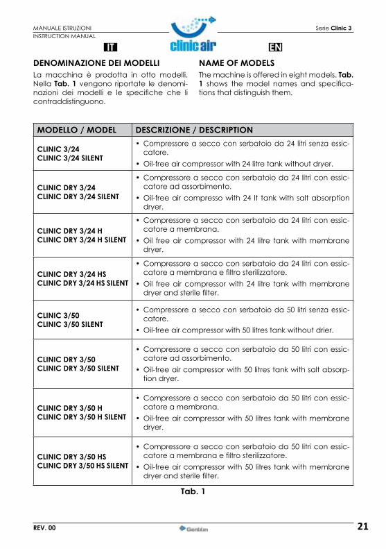
DENOMINAZIONE DEI MODELLILa macchina è prodotta in otto modelli. Nella Tab. 1 vengono riportate le denomi-nazioni dei modelli e le specifiche che li contraddistinguono.
INSTRUCTION MANUAL
ENNAME OF MODELSThe machine is offered in eight models. Tab. 1 shows the model names and specifica-tions that distinguish them.
MODELLO / MODEL DESCRIZIONE / DESCRIPTION
CLINIC 3/24CLINIC 3/24 SILENT
• Compressore a secco con serbatoio da 24 litri senza essic-catore.
• Oil-free air compressor with 24 litre tank without dryer.
CLINIC DRY 3/24CLINIC DRY 3/24 SILENT
• Compressore a secco con serbatoio da 24 litri con essic-catore ad assorbimento.
• Oil-free air compresso with 24 lt tank with salt absorption dryer.
CLINIC DRY 3/24 HCLINIC DRY 3/24 H SILENT
• Compressore a secco con serbatoio da 24 litri con essic-catore a membrana.
• Oil free air compressor with 24 litre tank with membrane dryer.
CLINIC DRY 3/24 HSCLINIC DRY 3/24 HS SILENT
• Compressore a secco con serbatoio da 24 litri con essic-catore a membrana e filtro sterilizzatore.
• Oil free air compressor with 24 litre tank with membrane dryer and sterile filter.
CLINIC 3/50CLINIC 3/50 SILENT
• Compressore a secco con serbatoio da 50 litri senza essic-catore.
• Oil-free air compressor with 50 litres tank without drier.
CLINIC DRY 3/50CLINIC DRY 3/50 SILENT
• Compressore a secco con serbatoio da 50 litri con essic-catore ad assorbimento.
• Oil-free air compressor with 50 litres tank with salt absorp-tion dryer.
CLINIC DRY 3/50 HCLINIC DRY 3/50 H SILENT
• Compressore a secco con serbatoio da 50 litri con essic-catore a membrana.
• Oil-free air compressor with 50 litres tank with membrane dryer.
CLINIC DRY 3/50 HSCLINIC DRY 3/50 HS SILENT
• Compressore a secco con serbatoio da 50 litri con essic-catore a membrana e filtro sterilizzatore.
• Oil-free air compressor with 50 litres tank with membrane dryer and sterile filter.
Tab. 1
22
IT
MANUALE ISTRUZIONI Serie Clinic 3
REV. 00
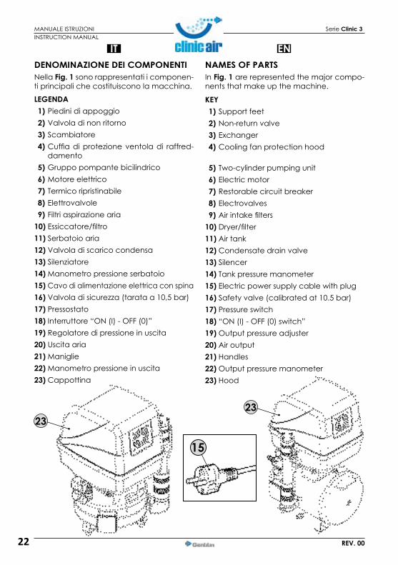
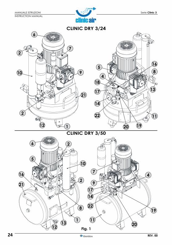
DENOMINAZIONE DEI COMPONENTINella Fig. 1 sono rappresentati i componen-ti principali che costituiscono la macchina.
LEGENDA 1) Piedini di appoggio 2) Valvola di non ritorno 3) Scambiatore 4) Cuffia di protezione ventola di raffred-
damento 5) Gruppo pompante bicilindrico 6) Motore elettrico 7) Termico ripristinabile 8) Elettrovalvole 9) Filtri aspirazione aria10) Essiccatore/filtro11) Serbatoio aria12) Valvola di scarico condensa13) Silenziatore14) Manometro pressione serbatoio15) Cavo di alimentazione elettrica con spina16) Valvola di sicurezza (tarata a 10,5 bar)17) Pressostato18) Interruttore “ON (I) - OFF (0)”19) Regolatore di pressione in uscita20) Uscita aria21) Maniglie22) Manometro pressione in uscita23) Cappottina
15
2323
INSTRUCTION MANUAL
ENNAMES OF PARTSIn Fig. 1 are represented the major compo-nents that make up the machine.
kEY 1) Support feet 2) Non-return valve 3) Exchanger 4) Cooling fan protection hood
5) Two-cylinder pumping unit 6) Electric motor 7) Restorable circuit breaker 8) Electrovalves 9) Air intake filters10) Dryer/filter11) Air tank12) Condensate drain valve13) Silencer14) Tank pressure manometer15) Electric power supply cable with plug16) Safety valve (calibrated at 10.5 bar) 17) Pressure switch18) “ON (I) - OFF (0) switch” 19) Output pressure adjuster20) Air output21) Handles22) Output pressure manometer23) Hood

23
MANUALE ISTRUZIONI Serie Clinic 3
REV. 00
CLINIC 3/24
CLINIC 3/50
Fig. 1
6
5
18
14
17
121
11
7
20
922
19
2
4
21
1122
4
14
20
75
6
11
21
9
1917
22
18
16
8
13
16
INSTRUCTION MANUAL
24
MANUALE ISTRUZIONI Serie Clinic 3
REV. 00
Fig. 1
CLINIC DRY 3/24
CLINIC DRY 3/5012 1
21
9
7
6
5
18
17
14
4
22
19
11
112
21
2
5
6
11
14
7
9
4
20
19
17
22
20
2
2
2
10
16
13
10
8
13
8
16
INSTRUCTION MANUAL

25
MANUALE ISTRUZIONI Serie Clinic 3
REV. 00
CLINIC DRY 3/50 H-HS
Fig. 1
CLINIC DRY 3/24 H-HS
312
21
7
1120
6
4
18
5
1
17
14
22
19
10
9
8
2
10
12
16
11
21
1
4
5
3
672
89
18
19
20
17
14
22
16
13
13
INSTRUCTION MANUAL

26
IT
MANUALE ISTRUZIONI Serie Clinic 3
REV. 00
DIMENSIONI DELLA MACCHINANella Tab.1 vengono riportate le dimensioni di ingombro della macchina rappresentate in Fig.1.
Fig. 1
Tab. 1
B B
B B
A A
A
A
C
C
CC
INSTRUCTION MANUAL
ENDIMENSIONS OF THE MACHINETab.1 gives the clearance of the machine represented in Fig.1.
MODELLO / MODELS A B CCLINIC 3/24 770 mm 410 mm 420 mmCLINIC 3/50 910 mm 460 mm 610 mmCLINIC DRY 3/24 770 mm 410 mm 510 mmCLINIC DRY 3/50 910 mm 460 mm 610 mmCLINIC DRY 3/24H 770 mm 445 mm 470 mmCLINIC DRY 3/50H 910 mm 490 mm 610 mmCLINIC DRY 3/24HS 770 mm 445 mm 470 mmCLINIC DRY 3/50HS 910 mm 490 mm 610 mm
50 LITRI LITERS
24 LITRI LITERS
27
IT
MANUALE ISTRUZIONI Serie Clinic 3
REV. 00
Tab. 2
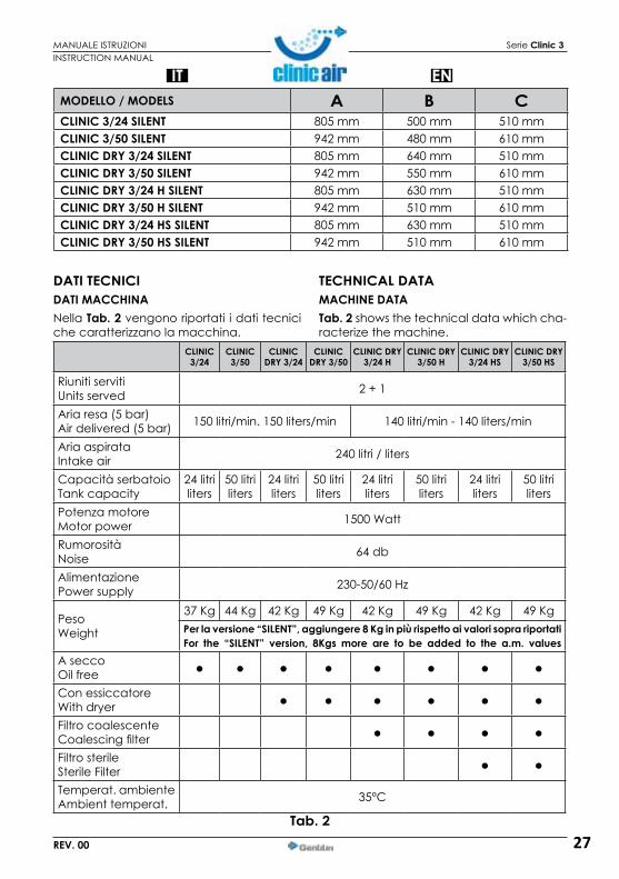
DATI TECNICIDATI MACCHINANella Tab. 2 vengono riportati i dati tecnici che caratterizzano la macchina.
INSTRUCTION MANUAL
EN
TECHNICAL DATAMACHINE DATATab. 2 shows the technical data which cha-racterize the machine.
CLINIC3/24
CLINIC3/50
CLINIC DRY 3/24
CLINIC DRY 3/50
CLINIC DRY 3/24 H
CLINIC DRY3/50 H
CLINIC DRY 3/24 HS
CLINIC DRY3/50 HS
Riuniti servitiUnits served 2 + 1
Aria resa (5 bar)Air delivered (5 bar) 150 litri/min. 150 liters/min 140 litri/min - 140 liters/min
Aria aspirataIntake air 240 litri / liters
Capacità serbatoioTank capacity
24 litriliters
50 litriliters
24 litriliters
50 litriliters
24 litriliters
50 litriliters
24 litriliters
50 litriliters
Potenza motoreMotor power 1500 Watt
RumorositàNoise 64 db
AlimentazionePower supply 230-50/60 Hz
PesoWeight
37 Kg 44 Kg 42 Kg 49 Kg 42 Kg 49 Kg 42 Kg 49 KgPerlaversione“SILENT”,aggiungere8Kginpiùrispettoaivalorisoprariportati For the “SILENT” version, 8Kgsmore are to be added to the a.m. values
A seccoOil freeCon essiccatoreWith dryerFiltro coalescenteCoalescing filterFiltro sterileSterile FilterTemperat. ambienteAmbient temperat. 35°C
MODELLO / MODELS A B CCLINIC 3/24 SILENT 805 mm 500 mm 510 mmCLINIC 3/50 SILENT 942 mm 480 mm 610 mmCLINIC DRY 3/24 SILENT 805 mm 640 mm 510 mmCLINIC DRY 3/50 SILENT 942 mm 550 mm 610 mmCLINIC DRY 3/24 H SILENT 805 mm 630 mm 510 mmCLINIC DRY 3/50 H SILENT 942 mm 510 mm 610 mmCLINIC DRY 3/24 HS SILENT 805 mm 630 mm 510 mmCLINIC DRY 3/50 HS SILENT 942 mm 510 mm 610 mm

28
IT
MANUALE ISTRUZIONI Serie Clinic 3
REV. 00
USO PREVISTO DELLA MACCHINALa macchina è stata progettata e realizza-ta per l’uso descritto in Tab. 1.
Tab. 1
INSTRUCTION MANUAL
ENINTENDED USE OF THE MACHINEThe machine was designed and built for the use described in Tab. 1.
CAMPO D’IMPIEGO Odontoiatria,laboratoriostudiodontoiatrici.
LUOGO DI UTILIZZO Luoghi al chiuso sufficientemente illuminati, ventilati, con aria ambiente avente le caratteristiche riportate al paragrafo “DATI TECNICI” e “PRODOTTI UTILIzzATI PER IL FUNZIONAMENTO”, idonei alle disposizioni legislative vigenti nel paese di utilizzazione in materia di sicurezza e salute nei luoghi di lavoro. La macchina deve essere appoggiata su di un piano che ne assicuri la stabilità in rapporto alle dimensioni di ingombro e al peso, rispet-tando le misure minime di posizionamento riportate al paragrafo “POSIZIONAMENTO DELLA MACCHINA”.
ATTENZIONE! È OBBLIGATORIO TENERE LA MACCHINA FUORI DALLA PORTATA DI PERSONE NON AUTORIZZATE.
USO PREVISTO Produzione di aria compressa per azionare gli utensili odontoiatrici.
OPERATORI ADDETTI ALL’UTILIZZO Un operatore autorizzato in possesso dei requisiti tecni-co professionali.
FIELD OF USE Dentistry,laboratoriesordentalcabinets.
PLACE OF USE Places indoors with sufficient lighting, ventilation, air en-vironment having the characteristics referred to under par. “MACHINE DATA” and “PRODUCT USED FOR OPE-RATION” appropriate to the laws in force in the country of use for safety and health in the workplace. The ma-chine must be placed on a plan that ensures stability in relation to the overall dimensions and weight, respec-ting the minimum position shown in par. “POSITIONING OF THE MACHINE”.
WARNING! YOU MUST kEEP THE MACHINE OUT OF REACH OF UNAUTHORIZED PERSONS.
INTENDED USE Compressed air production to operate dental tools.
OPERATORS IN CHARGE FOR USE
An authorized operator with the technical and profes-sional capacities meeting the requirements.

29
IT
MANUALE ISTRUZIONI Serie Clinic 3
REV. 00
FONTE ENERGETICA DI ALIMENTAZIONENella Tab. 2 viene elencata la fonte ener-getica di alimentazione della macchina.
PRODOTTI UTILIZZATI PER IL FUNZIONAMENTONella Tab. 3 viene riportato il prodotto utiliz-zato per il funzionamento.
FASI DI FUNZIONAMENTONella Tab. 4 vengono elencate le fasi di fun-zionamento della macchina (vedere relati-vi paragrafi).
Tab. 4
INSTRUCTION MANUAL
ENSOURCE OF ENERGY SUPPLYTab. 2 describes the source of energy sup-ply of the machine.
FONTE ENERGETICA / ENERGY SOURCE ALIMENTAZIONE / POWER SUPPLYELETTRICA
ELECTRIC
AC 230 V - 50/60 Hz - 8 ACollegamento tramite spina al quadro di di-stribuzione elettrica.
AC 230 V - 50/60 Hz - 8 AConnection via plug on electrical switchboard.
PRODUCTS USED FOR THE OPERATIONTab. 3 shows the product used for the ope-ration.
PHASES OF OPERATIONIn Tab. 4 are listed the steps of operation of the machine (please see the relative para-graphs).
PRODOTTO UTILIZZATO - PRODUCTS USED FOR THE OPERATION
Aria ambiente “pulita” (di buona qualità) priva di inquinanti nocivi per la salute.
Ambient air “clean” (good quality) free of pollutants harmful to health.
Filtri aspirazione aria (in carta)
Intake air filters (paper)
Essiccatore/filtri
Dryer /filters
FASE - PHASE LAVORAZIONE - OPERATION1 Accensione della macchina / Turning on the machine.
2 Regolazione della pressione in uscita / Adjusting the outlet pressure.
3 Se richiesto reset del termico ripristinabile If requested reset the resettable thermal.
4 Spegnimento della macchina / Turning off the machine.
Tab. 2
Tab. 3

30
IT
MANUALE ISTRUZIONI Serie Clinic 3
REV. 00
USO SCORRETTO RAGIONEVOLMENTE PREVEDIBILELa macchina è stata progettata e realizza-ta per l’uso previsto, pertanto è assoluta-mente vietato ogni altro tipo di impiego e utilizzo, al fine di garantire in ogni momento la sicurezza degli operatori autorizzati e l’ef-ficienza della macchina stessa.
PERICOLO DI SCOTTATURE PER CON-TATTO ACCIDENTALE CON GRUPPO POMPANTE BICILINDRICO E MOTORE
ELETTRICO. ATTENZIONE ESISTE UN RISCHIO RESIDUO.
È OBBLIGATORIO INSTALLARE LA MACCHINA IN UN LUOGO DI UTILIZZO AVENTE LE CARATTERISTICHE RIPOR-
TATE AL PAR. “USO PREVISTO DELLA MAC-CHINA”.
È OBBLIGATORIO UTILIZZARE LA MACCHINA NEL RISPETTO DELLA LEGISLAZIONE VIGENTE NEL PAESE DI UTILIZZAZIONE IN MATERIA DI IMMISSIONI(RUMORE).
È OBBLIGATORIO TENERE LA MACCHINA FUORI DALLA PORTATA DI PERSONE NON AUTORIZZATE.
È ASSOLUTAMENTE VIETATO L’IMPIE-GO E L’UTILIZZO DELLA MACCHINA PERUSIIMPROPRIEDIVERSIDAQUEL-
LO PREVISTO DAL FABBRICANTE.
È ASSOLUTAMENTE VIETATO L‘UTILIZZO DELLA MACCHINA ALL’APERTO.
È ASSOLUTAMENTE VIETATO L’IMPIEGO DI TUBIARIA(PROLUNGHE),RACCORDIEUTEN-SILI NON IDONEI E/O NON CONFORMI ALLE NORMATIVE VIGENTI.
È ASSOLUTAMENTE VIETATO SOLLEVARE LA MACCHINA CON GRU E/O CARRELLO ELE-VATORE.
È ASSOLUTAMENTE VIETATO DIRIGERE GETTI D’ARIA COMPRESSA CONTRO PERSONE E/O ANIMALI.
È ASSOLUTAMENTE VIETATO SALIRE SULLA MACCHINA.
INSTRUCTION MANUAL
ENREASONABLY FORESEEABLE MISUSEThe machine was designed and built for use provided, therefore it is absolutely prohibi-ted any other type of application and use, in order to ensure at all times the safety of the Authorized operators and the efficiency of the machine itself.
RISk OF BURNS DUE TO ACCIDENTAL CONTACT WITH THE PUMPING GROUP AND ELECTRIC MOTOR AND PUMP
UNIT. WARNING THERE IS A RESIDUAL RISk.
IT IS COMPULSORY TO INSTALL THE MACHINE IN A PLACE OF USE HA-VING THE CHARACTERISTICS INDICA-
TED ON PAR. “INTENDED USE OF THE MACHI-NE”.
IT IS COMPULSORY TO USE THE MACHINE IN THE RESPECT OF THE LEGISLATION IN FORCE IN THE COUNTRY OF USE CONCERNING IN-TRODUCTIONS(NOISE).
IT IS COMPULSORY TO kEEP THE MACHINE OUT OF REACH OF UNAUTHORIZED PERSONS.
IT IS STRICTLY PROHIBITED THE USE OF THE MACHINE FOR MISUSE AND DIFFE-RENT USES FROM THE ONE INTENDED
BY THE MANUFACTURER.
IT IS ABSOLUTELY FORBIDDEN TO USE THE MA-CHINE OUTDOORS.
IT IS STRICTLY PROHIBITED THE USE OF AIR TU-BES(EXTENSIONS),FITTINGSANDNOTSUITA-BLE TOOLS AND/OR NOT CONFORM TO THE STANDARDS IN FORCE.
IT IS ABSOLUTELY FORBIDDEN TO LIFT THE MA-CHINE WITH CRANE AND/OR FORkLIFT.
IT IS ABSOLUTELY FORBIDDEN TO LEAD AIR JETS AGAINST PERSONS AND/OR ANIMALS.
DO NOT CLIMB ONTO THE MACHINE.

31
IT
MANUALE ISTRUZIONI Serie Clinic 3
REV. 00
È ASSOLUTAMENTE VIETATA LA MESSA IN SERVIZIO DELLA MACCHINA IN AMBIENTI CON ATMOSFERA POTEN-
ZIALMENTE ESPLOSIVA E/O IN PRESENZA DI POLVERI COMBUSTIBILI (ES: POLVERE DI LE-GNO,FARINE,ZUCCHERIEGRANAGLIE).
INSTRUCTION MANUAL
ENIT IS STRICTLY PROHIBITED TO COM-MISSION THE MACHINE IN ENVI-RONMENTSWITHPOTENTIALLYEXPLO-
SIVE ATMOSPHERE AND/OR IN THE PRESENCE OF COMBUSTIBLE DUSTS (E.G.: WOODPOWDER,FLOUR,SUGARSANDGRAINS).
32
IT
MANUALE ISTRUZIONI Serie Clinic 3
REV. 00
TRASPORTO E MOVIMENTAZIONE
TRASPORTO DELLA MACCHINALa macchina viene trasportata pres-so il cliente tramite una “ditta di tra-sporti specializzata” o dal Fabbrican-te che, mediante proprio personale, mezzi idonei all’impiego e nel rispet-to delle normative vigenti, provvede
a garantire le operazioni d’imballo, solleva-mento, carico, trasporto e scarico relativa-mente alla tipologia di trasporto (via terra, via mare o via aerea).
TUTTE LE OPERAZIONI DI SOLLEVA-MENTO,CARICO,TRASPORTOESCA-RICO DELLA MACCHINA DEVONO
OBBLIGATORIAMENTE ESSERE ESEGUITE DA UNA “DITTA DI TRASPORTI SPECIALIZZATA” O DAL FABBRICANTE CON PERSONALE E MEZZI IDONEI ALL’IMPIEGO.
IMBALLOLa macchina viene fissata al pallet tramite regge e coperta con una sca-tola di cartone. L’imballo contiene:• N. 1 compressore• N. 1 manuale di istruzioni
Le caratteristiche dell’imballo sono riporta-te in Tab. 1.
Tab. 1
INSTRUCTION MANUAL
ENTRANSPORTATION
AND HANDLING TRANSPORTATION OF THE MACHINE
The machine is delivered to the cus-tomer through a “specialized trans-portation company” or by the man-ufacturer who, through its own personnel and appropriate means, in compliance with the regulations,
shall ensure the operations of packaging, lifting, loading, transport and unloading in relation to the type of transport (land, sea or air).
ALLOPERATIONSOF LIFTING, LOAD-ING, TRANSPORT AND UNLOADINGOFTHEMACHINEREQUIRETOBEPER-
FORMED BY A “SPECIALIZED TRANSPORT COMPANY” OR BY THE MANUFACTURER WITH PERSONNEL AND MEANS SUITABLE FOR USE.
PACkAGINGThe machine is fixed to the pallet by straps and covered with a cardboard box. The packaging contains:• No. 1 compressor• No. 1 instruction manual
The characteristics of the packaging are in-dicated in Tab. 1.
Mod. CLINIC3/24
CLINIC3/50
CLINIC DRY 3/24
CLINIC DRY3/50
CLINIC DRY
3/24 H
CLINIC DRY
3/50 H
CLINIC DRY
3/24 HS
CLINIC DRY
3/50 HS
Peso imballo kg
Packaging Weight40 Kg 47 Kg 45 Kg 52 Kg 45 Kg 52 Kg 45 Kg 52 Kg
Misure imballo(macchina + altezza bancale)
Pack measurement(machine + bed height)
H9566×55
H11066×55
H9566×55
H11066×55
H9566×55
H11066×55
H9566×55
H11066×55
Perlaversione“SILENT”,aggiungere8KginpiùrispettoaivalorisoprariportatiForthe“SILENT”version,8Kgsmorearetobeaddedtothea.m.values

33
IT
MANUALE ISTRUZIONI Serie Clinic 3
REV. 00
MOVIMENTAZIONE DELL’IMBALLO CONCARRELLO ELEVATORE O TRANSPALLET
È OBBLIGATORIO CHE, NEL RAGGIOD’AZIONE DELLE OPERAZIONI DI MOVI-MENTAZIONE,NONVISIANOPERSONE,ANIMALI E/O COSE LA CUI INCOLUMI-TÀ POSSA ESSERE ACCIDENTALMENTE COMPROMESSA.LA MOVIMENTAZIONE DELL’IMBALLO PUÒ ESSERE ESEGUITA SOLO CON L’UTI-LIZZO DI UN TRANSPALLET O DI UN CAR-RELLO ELEVATORE IDONEI ALL’IMPIEGO.
ÈOBBLIGATORIO,DURANTELEOPERAZIONIDISOLLEVAMENTO (SALITA/DISCESA), NON EF-FETTUARE BRUSCHE MANOVRE CHE COMPRO-METTANO LA STABILITÀ DEL CARICO.
1) Inserire le forche (2-Fig.1) sotto al pallet (1), mantenendole al centro di quest’ulti-mo.
2) Sollevare l’imballo (3) di qualche centi-metro per controllare che il carico sia ef-fettivamente centrato rispetto alle forche.
3) Con prudenza effettuare lo spostamen-to dell’imballo fino al luogo di posiziona-mento
SBALLAGGIODopo avere appoggiato l’imballo a terra procedere allo sballaggio come segue:
1) Con utensile idoneo, tagliare le regge (4) facendo attenzione a non essere colpiti dalle stesse per effetto dell’elasticità.
Fig. 11
2
34
INSTRUCTION MANUAL
ENHANDLING OF PACkAGING WITH A FORkLIFT OR TRANSPALLET
ITISMANDATORYTHAT,INTHERANGEOF HANDLING OPERATIONS, THEREARE NO PEOPLE, ANIMALS AND/ORTHINGS WHOSE SAFETY CAN BE COM-PROMISED ACCIDENTALLY.
THE HANDLING OF THE PACkAGE CAN BE PERFORMED ONLY BY THE USE OF A TRANSPALLET OR A FORkLIFT SU-ITABLE FOR USE.
ITISMANDATORY,DURINGTHELIFTINGOPE-RATIONS, (UP/DOWN), NOT TOMAKE SUD-DEN MANOEUVRES AFFECTING STABILITY OF LOAD.
1) Insert the forks (2-Fig.1) under the pallet (1), keeping them at the centre of the lat-ter.
2) Raise the packaging (3)a few centime-tres to make sure the load is actually cen-tred in the forks.
3) Carefully move the package to the posi-tioning area expected, therefore lowering the load until the full stability is reached.
UNPACkINGAfter laying the packaging on the ground do the unpacking as follows:
1) With a suitable tool, cut the straps (4) ta-king care not to be affected by the straps as a result.
LATOSXLEFT SIDE

34
IT
MANUALE ISTRUZIONI Serie Clinic 3
REV. 00
2) Sfilare la scatola di cartone.
SI RACCOMANDA DI SMALTIRE L’IMBALLO SECONDO LE DIVERSE TIPOLOGIE DI MATE-RIALE NELL’ASSOLUTO RISPETTO DELLA LEGI-SLAZIONE VIGENTE NEL PAESE DI UTILIZZA-ZIONE.
MOVIMENTAZIONE MANUALE DELLA MACCHINA
LA MOVIMENTAZIONE MANUALE DEL-LA MACCHINA DEVE ESSERE ESEGUI-TA DA ALMENO DUE OPERATORI AD-
DETTI,ODUTILIZZANDOUNMEZZO IDONEO(ES.:TRANSPALLET),NELRISPETTODELLENOR-MATIVE SULLA “MOVIMENTAZIONE MANUA-LEDEICARICHI”,ONDEEVITARECONDIZIO-NI ERGONOMICHE SFAVOREVOLI CHE COMPORTINO RISCHI DI LESIONI DORSO-LOMBARI.
La macchina può essere movimentata manualmente da due operatori addetti, tramite le maniglie (1-Fig.1) di cui è do-tata. Assicurarsi che la spina del cavo di ali-mentazione elettrica sia scollegata e che il cavo sia posizionato sopra il serbatoio.
MOD. 24 L MOD. 50 L
Fig. 1
INSTRUCTION MANUAL
EN2) Remove the cardboard box.
BE SURE TO DISPOSE THE PACkAGING MA-TERIAL ACCORDING TO THE DIFFERENT TYPES OF MATERIAL IN THE ABSOLUTE RESPECT OF THE LEGISLATION IN FORCE IN THE COUNTRY OF USE.
MANUAL HANDLING OF THEMACHINE
THE MANUAL HANDLING OF THE MA-CHINE MUST BE DONE BY AT LEAST TWO OPERATORS IN CHARGE, OR
USING A SUITABLE MEAN (E.G.: TRANSPAL-LET), IN ACCORDANCE WITH THE REGULA-TIONS ON THE “MANUAL HANDLING OF LO-ADS”, IN ORDER TO AVOID ADVERSECONDITIONS THAT INVOLVE RISk OF ERGO-NOMIC INJURIES TO THE BACk.
The machine can be moved manually by two operators in charge, using the handles (1-Fig.1) that are attached. Make sure the plug of the power supply cable is discon-nected and that the cord is positioned abo-ve the tank.
LATO POSTERIOREREAR SIDE
LATODXRH SIDE

35
IT
MANUALE ISTRUZIONI Serie Clinic 3
REV. 00
Fig. 2
POSIZIONAMENTO DELLA MACCHINALa macchina deve essere impiegata in un luogo di lavoro con le caratteri-stiche descritte al par. “USO PREVI-STO DELLA MACCHINA”, posizionata su di un pavimento piano che ne as-sicuri la stabilità in rapporto alle di-mensioni d‘ingombro e al peso.
PER ASSICURARE AGLI OPERATORI AU-TORIZZATI LA POSSIBILITÀ DI OCCUPARE I POSTI DI LAVORO PREVISTI, È OBBLI-
GATORIO GARANTIRE LE MISURE MINIME DI POSIZIONAMENTO RIPORTATE NELLA FIG. 2. SE LATEMPERATURAAMBIENTALE,DOVEÈSTATAPOSIZIONATALAMACCHINA,SUPERAIVALO-RIINDICATIALPARAGRAFO“DATITECNICI”,ÈOBBLIGATORIO INSTALLARE UN IDONEO E CONFORME IMPIANTO DI VENTILAZIONE AG-GIUNTIVO,COMEINDICATOINFIG.2.
INSTRUCTION MANUAL
EN
VISTA IN PIANTA / PLAN VIEW LATOSX/LHSIDE
POSITIONING OF THE MACHINEThe machine must be placed in a workplace with the characteristics described in par. “INTENDED USE OF THE MACHINE”, placed on a flat floor that ensures stability in relation to the overall dimensions and to the weight.
IN ORDER TO ENSURE THAT THE AU-THORIZED OPERATORS OCCUPY THE WORK POSITIONS EXPECTED, IT IS
MANDATORY TO ENSURE MINIMUM MEASU-RES OF POSITIONING AS SHOWN IN FIG. 2. IF THE ROOM TEMPERATURE, WHERE THE MA-CHINEHAS BEEN PLACED, EXCEEDS THE LI-MITS SPECIFIED IN PAR.“TECHNICAL SPECIFI-CATIONS”,ITISCOMPULSORYTOINSTALLASUITABLE ADDITIONAL FAN, AS SHOWN INFIG. 2.

36
IT
MANUALE ISTRUZIONI Serie Clinic 3
REV. 00
INSTALLAZIONEAVVERTENZE GENERALI
È OBBLIGATORIO RISPETTARE LE COR-RETTE PROCEDURE DI MONTAGGIO/SMONTAGGIO E COLLEGAMENTO DEI
COMPONENTI DESCRITTE NEL PRESENTE CA-PITOLO. LA MOVIMENTAZIONE MANUALE DEVE AVVENIRE NEL RISPETTO DELLE NOR-MATIVE VIGENTI SULLA “MOVIMENTAZIONE MANUALE DEI CARICHI” ONDE EVITARE CONDIZIONI ERGONOMICHE SFAVOREVOLI CHE COMPORTINO RISCHI DI LESIONI DOR-SO-LOMBARI.TUTTE LE OPERAZIONI DI SEGUITO DESCRITTE SERVONO A PREDISPORRE LA MACCHINA PRONTA PER IL FUNZIONAMENTO.
COLLEGAMENTO PNEUMATICOIL FABBRICANTE DECLINA OGNI RE-SPONSABILITÀPERDANNIAPERSONE,ANIMALIE/OCOSE,CAUSATIDALL’I-
NOSSERVANZA DELLE AVVERTENZE SOPRA-DESCRITTE.
È ASSOLUTAMENTE VIETATO L’IM-PIEGO DI TUBI ARIA (PROLUNGHE),RACCORDI E UTENSILI NON IDONEI E
NON CONFORMI ALLE NORMATIVE VIGENTI.
È OBBLIGATORIO UTILIZZARE TUBI ARIA (PROLUNGHE), RACCORDI EUTENSILI,CONFORMEMENTEAQUAN-
TO PREVISTO DAI “MANUALI DI ISTRUZIONI” FORNITI DAI RELATIVI FABBRICANTI.
La macchina deve essere collegata a monte di un impianto pneumatico per la produzione di aria sterilizzata (a cura del Cliente) allacciando all’uscita aria (20-Fig.1), il tubo aria di ingresso dell’impianto provvisto di apposito attacco.
INSTRUCTION MANUAL
ENINSTALLATION
GENERAL WARNINGSIT IS COMPULSORY TO COMPLY WITH THE CORRECT PROCEDURES OF AS-SEMBLY/DISASSEMBLY AND CON-
NECTION OF COMPONENTS DESCRIBED IN THIS CHAPTER.THE MANUAL HANDLING MUST BE IN COM-PLIANCE WITH THE REGULATIONS ON THE “MANUAL HANDLING OF LOADS” IN ORDER TO AVOID ADVERSE CONDITIONS THAT IN-VOLVE RISk OF INJURIES TO THE BACk.ALL OPERATIONS DESCRIBED BELOW ARE DONE TO PREPARE THE MACHINE READY FOR THE OPERATION.
PNEUMATIC CONNECTIONTHE MANUFACTURER HAS NO LIABILI-TYFORINJURYTOPERSONS,ANIMALSAND/OR THINGS, RESULTING FROM
FAILURE TO OBSERVE THE WARNINGS DE-SCRIBED ABOVE.
IT IS STRICTLY PROHIBITED THE USE OF AIR TUBES (EXTENSIONS), FITTINGSAND TOOLS NOT SUITABLE AND NOT
CONFORM TO THE REGULATIONS IN FORCE.
IT IS COMPULSORY TO USE AIR TUBES (EXTENSIONS), FITTINGS AND TOOLS,ACCORDING TO WHAT IS FORECAST
IN THE “INSTRUCTION MANUALS” PROVIDED BY THE MANUFACTURERS.
The machine must be connected upstream to a pneumatic system for the production sterilized air (by cu-stomer) connecting, to the air outlet (20 - Fig.1), the tube for air inlet of the system equipped with a special fitting.

37
MANUALE ISTRUZIONI Serie Clinic 3
REV. 00
Fig. 1
COLLEGAMENTO ELETTRICOIL FABBRICANTE DECLINA OGNI RE-SPONSABILITÀ PER GUASTI O ANO-MALIE DI FUNZIONAMENTO DELLA
MACCHINA CAUSATI DA SBALZI DI TENSIONE ELETTRICA CHE SUPERANO LE TOLLERANZE PREVISTEDALL’ENTEDISTRIBUTORE(TENSIONE±10%-FREQUENZA±2%).
LA RETE DI ALIMENTAZIONE ELETTRICA A CUI VIENE COLLEGATA LA MACCHI-NA DEVE ESSERE CONFORME AI RE-
QUISITIPREVISTIALLALEGISLAZIONEVIGENTENELPAESEDIUTILIZZAZIONE,SODDISFARELECARATTERISTICHE TECNICHE RIPORTATE NEL PAR. “DATI MACCHINA” ED ESSERE DOTATA DI UN IDONEO IMPIANTO DI “MESSA A TER-RA”. È OBBLIGATORIO INSTALLARE A MONTE DELLA LINEA DI ALIMENTAZIONE ELETTRICA UN IDONEO DISPOSITIVO DI SEZIONAMENTO CON PROTEZIONE DIFFERENZIALE COORDI-NATO CON L’IMPIANTO DI MESSA A TERRA.
20
20
INSTRUCTION MANUAL
ELECTRIC CONNECTIONTHE MANUFACTURER HAS NO LIABILI-TY FOR FAILURE OR MALFUNCTIONS OF OPERATION TO THE MACHINE
CAUSED BY VOLTAGE DROPS EXCEEDINGTHE TOLERANCES PROVIDED BY THE DISTRIBU-TINGBODY (± 10%POWER - FREQUENCY±2%).
THE MAINS TO WHICH THE MACHINE IS CONNECTED MUST BE IN ACCOR-DANCE WITH THE REQUIREMENTS OF
THELAWSOFTHECOUNTRYOFUSE,MEETTHESPECIFICATIONS CONTAINED IN PAR. “MA-CHINE DATA” AND BE PROVIDED WITH A SUI-TABLE GROUNDING SYSTEM.IT IS COMPULSORY TO INSTALL UPSTREAM OF THE POWER SUPPLY LINE AN ELECTRIC CUT-TING DEVICE WITH A SUITABLE DISCONNEC-TING PROTECTION COORDINATED WITH THE GROUNDING PLANT.

38
IT
MANUALE ISTRUZIONI Serie Clinic 3
REV. 00
QUALSIASITIPODIMATERIALEELETTRICOUTI-LIZZATO PER IL COLLEGAMENTO DEVE ESSERE IDONEO ALL’IMPIEGO, MARCATO “CE” SESOGGETTO ALLA DIRETTIVA BASSA TENSIO-NE 2006/95/CE E CONFORME AI REQUISITIRICHIESTI DALLE NORMATIVE VIGENTI NEL PAESE DI UTILIZZAZIONE DELLA MACCHINA. QUALORA SI RENDA NECESSARIO, È OB-BLIGATORIO COLLEGARE LA MACCHINA ESCLUSIVAMENTE A GENERATORI DI COR-RENTE ELETTRICA CON POTENZA MAGGIORE DELLAPOTENZAELETTRICA INSTALLATA, PERSOPPORTARE LO SPUNTO DI ASSORBIMENTO ALL’AVVIO.IL MANCATO RISPETTO DELLE AVVERTENZE SOPRA DESCRITTE PUÒ CAUSARE DANNI IR-REPARABILI ALL’APPARATO ELETTRICO DELLA MACCHINA E LA CONSEGUENTE DECADEN-ZA DELLA GARANZIA.
La macchina può essere collegata alla rete di alimentazione elettrica inserendo la spina del cavo di ali-mentazione elettrica (15)nella presa di alimentazione elettrica (a cura del Cliente).
15
INSTRUCTION MANUAL
ENANY TYPE OF ELECTRIC MATERIAL USED FOR THE CONNECTION MUST BE SUITABLE FOR USE,MARKED“CE”IFSUBJECTTOLOWVOL-TAGE DIRECTIVE 2006/95/EC AND COM-PLYINGWITHTHEREQUIREMENTSOFTHERE-GULATIONS IN FORCE IN THE COUNTRY OF USE OF THE MACHINE.IFNECESSARY,ITISCOMPULSORYTOCON-NECT THE MACHINE ONLY TO GENERATORS OF ELECTRICITY WITH A POWER GREATER THAN THE POWER SUPPLY INSTALLED, TOSUPPORT THE ABSORPTION CURRENT UPON STARTUP.
FAILURE TO FOLLOW THE WARNINGS ABOVE MAY CAUSE IRREVERSIBLE DAMAGE TO THE ELECTRICEQUIPMENTOFTHEMACHINEANDTHESUBSEQUENTVOIDOFTHEWARRANTY.
The machine can be connected to the mains by plugging the power cord (15) into the power outlet (by the Customer).
39
IT
MANUALE ISTRUZIONI Serie Clinic 3
REV. 00
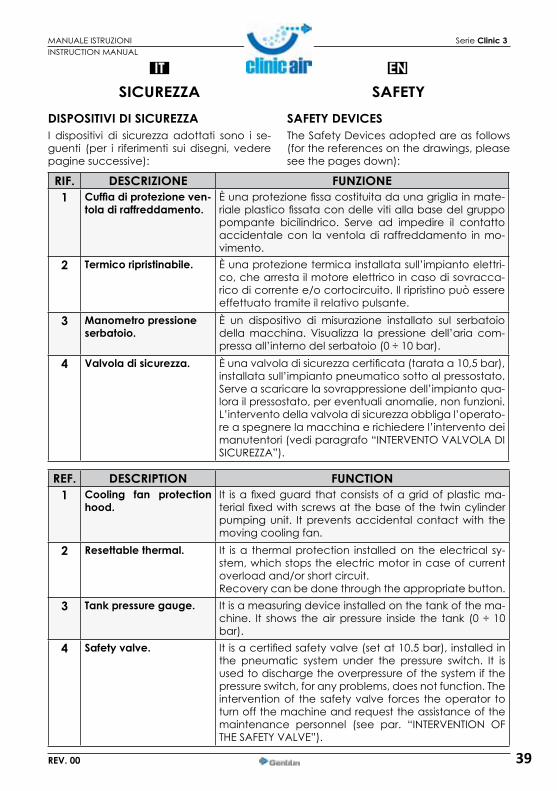
SICUREZZADISPOSITIVI DI SICUREZZAI dispositivi di sicurezza adottati sono i se-guenti (per i riferimenti sui disegni, vedere pagine successive):
RIF. DESCRIZIONE FUNZIONE1 Cuffiadiprotezioneven-
tola di raffreddamento.È una protezione fissa costituita da una griglia in mate-riale plastico fissata con delle viti alla base del gruppo pompante bicilindrico. Serve ad impedire il contatto accidentale con la ventola di raffreddamento in mo-vimento.
2 Termico ripristinabile. È una protezione termica installata sull’impianto elettri-co, che arresta il motore elettrico in caso di sovracca-rico di corrente e/o cortocircuito. Il ripristino può essere effettuato tramite il relativo pulsante.
3 Manometro pressione serbatoio.
È un dispositivo di misurazione installato sul serbatoio della macchina. Visualizza la pressione dell’aria com-pressa all’interno del serbatoio (0 ÷ 10 bar).
4 Valvola di sicurezza. È una valvola di sicurezza certificata (tarata a 10,5 bar), installata sull’impianto pneumatico sotto al pressostato. Serve a scaricare la sovrappressione dell’impianto qua-lora il pressostato, per eventuali anomalie, non funzioni. L’intervento della valvola di sicurezza obbliga l’operato-re a spegnere la macchina e richiedere l’intervento dei manutentori (vedi paragrafo “INTERVENTO VALVOLA DI SICUREZZA”).
INSTRUCTION MANUAL
ENSAFETY
SAFETY DEVICESThe Safety Devices adopted are as follows (for the references on the drawings, please see the pages down):
REF. DESCRIPTION FUNCTION1 Cooling fan protection
hood.It is a fixed guard that consists of a grid of plastic ma-terial fixed with screws at the base of the twin cylinder pumping unit. It prevents accidental contact with the moving cooling fan.
2 Resettablethermal. It is a thermal protection installed on the electrical sy-stem, which stops the electric motor in case of current overload and/or short circuit.Recovery can be done through the appropriate button.
3 Tank pressure gauge. It is a measuring device installed on the tank of the ma-chine. It shows the air pressure inside the tank (0 ÷ 10 bar).
4 Safetyvalve. It is a certified safety valve (set at 10.5 bar), installed in the pneumatic system under the pressure switch. It is used to discharge the overpressure of the system if the pressure switch, for any problems, does not function. The intervention of the safety valve forces the operator to turn off the machine and request the assistance of the maintenance personnel (see par. “INTERVENTION OF THE SAFETY VALVE”).

40
IT
MANUALE ISTRUZIONI Serie Clinic 3
REV. 00
È OBBLIGATORIO CONTROLLARE CO-STANTEMENTE IL BUON FUNZIONA-MENTO E L’EFFICIENZA DI TUTTI I DI-
SPOSITIVI DI SICUREZZA PRESENTI NELLA MACCHINA. È OBBLIGATORIO SOSTITUIRE TEMPESTIVA-MENTE EVENTUALI DISPOSITIVI DI SICUREZZA MALFUNZIONANTI E/O DANNEGGIATI.
È VIETATOMANOMETTERE, ESCLUDE-RE,RIMUOVEREE/OSOSTITUIREQUAL-SIASI DISPOSITIVO DI SICUREZZA PRE-
SENTE NELLA MACCHINA. È ASSOLUTAMENTE VIETATO SOSTITUIRE QUALUNQUEDISPOSITIVODISICUREZZAODUN SUO COMPONENTE CON RICAMBI NON ORIGINALI.
RIF. DESCRIZIONE FUNZIONE5 Pressostato. È un dispositivo elettro-pneumatico (tarato a min. 6 bar
max. 8 bar) installato sull’impianto pneumatico.Serve a comandare l’avvio automatico della macchi-na quando la pressione di esercizio scende a 6 bar e l’arresto automatico quando la pressione di esercizio raggiunge i 8 bar.
6 Manometro pressione in uscita.
È un dispositivo di misurazione installato sull’impianto pneumatico della macchina a monte del rubinetto ra-pido uscita aria. Visualizza la pressione in uscita, rego-labile tramite l’apposito regolatore di pressione (0 ÷ 10 bar).
INSTRUCTION MANUAL
EN
IT IS COMPULSORY TO CONSTANTLY CHECk THE GOOD FUNCTIONING AND THE EFFICIENCY OF ALL SAFETY
DEVICES IN THIS MACHINE.
IT IS COMPULSORY TO REPLACE ANY SAFETY DEVICES MALFUNCTIONING AND/OR DA-MAGED.
IT IS FORBIDDEN TO MANIPULATE,EXCLUDE,REMOVEAND/ORREPLACEANY SAFETY DEVICE IN THIS MACHI-
NE.IT IS ABSOLUTELY FORBIDDEN TO REPLACE ANY SAFETY DEVICE OR COMPONENT WITH NON ORIGINAL SPARE PARTS.
REF. DESCRIPTION FUNCTION5 Pressureswitch. It is an electro-pneumatic device (set at min. 6 bar, max.
8 bar) fitted onto the pneumatic plant.It is used to control the automatic start of the machine when the pressure drops to 6 bars and the automatic stop when the pressure reaches 8 bars.
6 Outlet pressure gauge. It is a measuring device installed on the pneumatic plant of the machine upstream of the fast valve of air outlet. It shows the outlet pressure, adjustable through the proper pressure regulator (0 ÷ 10 bar).
41
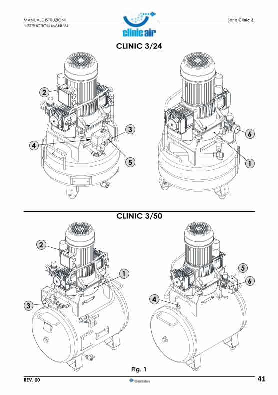
MANUALE ISTRUZIONI Serie Clinic 3
REV. 00
CLINIC 3/24
CLINIC 3/50
Fig. 1
3
5
2
6
1
3
2
5
6
4
1
4
INSTRUCTION MANUAL
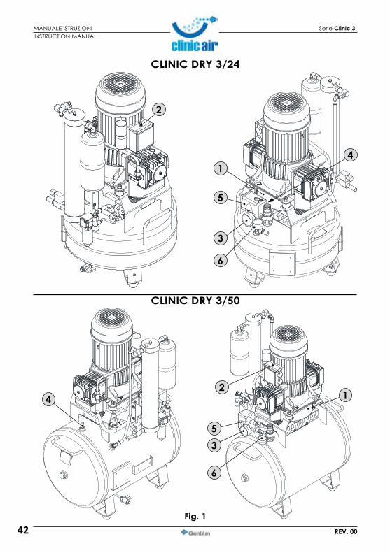
42
MANUALE ISTRUZIONI Serie Clinic 3
REV. 00
Fig. 1
CLINIC DRY 3/24
CLINIC DRY 3/50
2
1
5
3
6
3
21
5
6
4
4
INSTRUCTION MANUAL

43
MANUALE ISTRUZIONI Serie Clinic 3
REV. 00
CLINIC DRY 3/50 H-HS
Fig. 1
CLINIC DRY 3/24 H-HS
1
2
5
3
4
6
4
1
2
5
3
6
INSTRUCTION MANUAL
44
IT
MANUALE ISTRUZIONI Serie Clinic 3
REV. 00
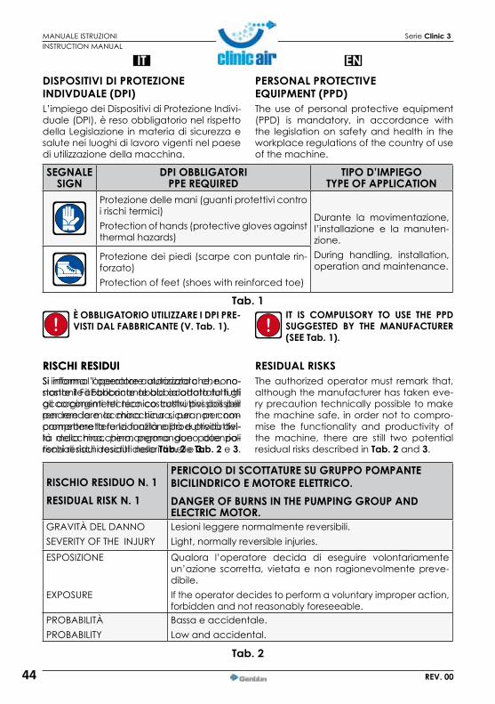
DISPOSITIVI DI PROTEZIONE INDIVDUALE(DPI)L’impiego dei Dispositivi di Protezione Indivi-duale (DPI), è reso obbligatorio nel rispetto della Legislazione in materia di sicurezza e salute nei luoghi di lavoro vigenti nel paese di utilizzazione della macchina.
È OBBLIGATORIO UTILIZZARE I DPI PRE-VISTIDALFABBRICANTE(V.Tab.1).
Tab. 1
Tab. 2
RISCHI RESIDUISi informa l’operatore autorizzato che, no-nostante il Fabbricante abbia adottato tutti gli accorgimenti tecnico costruttivi possibili per rendere la macchina sicura, per non compromettere la funzionalità e produttivi-tà della macchina, permangono due po-tenziali rischi residui descritti nelle Tab. 2 e 3.
INSTRUCTION MANUAL
ENPERSONAL PROTECTIVE EQUIPMENT(PPD)The use of personal protective equipment (PPD) is mandatory, in accordance with the legislation on safety and health in the workplace regulations of the country of use of the machine.
SEGNALESIGN
DPI OBBLIGATORIPPEREQUIRED
TIPO D’IMPIEGOTYPE OF APPLICATION
Protezione delle mani (guanti protettivi contro i rischi termici)Protection of hands (protective gloves against thermal hazards)
Durante la movimentazione, l’installazione e la manuten-zione.During handling, installation, operation and maintenance.
Protezione dei piedi (scarpe con puntale rin-forzato)Protection of feet (shoes with reinforced toe)
IT IS COMPULSORY TO USE THE PPD SUGGESTED BY THE MANUFACTURER (SEETab.1).
RISCHIO RESIDUO N. 1RESIDUAL RISk N. 1
PERICOLO DI SCOTTATURE SU GRUPPO POMPANTEBICILINDRICO E MOTORE ELETTRICO.DANGER OF BURNS IN THE PUMPING GROUP AND ELECTRIC MOTOR.
GRAVITÀ DEL DANNOSEVERITY OF THE INJURY
Lesioni leggere normalmente reversibili.Light, normally reversible injuries.
ESPOSIzIONE
EXPOSURE
Qualora l’operatore decida di eseguire volontariamente un’azione scorretta, vietata e non ragionevolmente preve-dibile.If the operator decides to perform a voluntary improper action, forbidden and not reasonably foreseeable.
PROBABILITÀPROBABILITY
Bassa e accidentale.Low and accidental.
RISCHI RESIDUISi informa l’operatore autorizzato che, nono-stante il Fabbricante abbia adottato tutti gli accorgimenti tecnico costruttivi possibili per rendere la macchina sicura, per non com-promettere la funzionalità e produttività del-la macchina, permangono due potenziali rischi residui descritti nelle Tab. 2 e 3.
RESIDUAL RISkSThe authorized operator must remark that, although the manufacturer has taken eve-ry precaution technically possible to make the machine safe, in order not to compro-mise the functionality and productivity of the machine, there are still two potential residual risks described in Tab. 2 and 3.

45
IT
MANUALE ISTRUZIONI Serie Clinic 3
REV. 00
Tab. 3
INSTRUCTION MANUAL
EN
RISCHIO RESIDUO N. 1RESIDUAL RISk N. 1
PERICOLO DI SCOTTATURE SU GRUPPO POMPAN-TE BICILINDRICO E MOTORE ELETTRICO.DANGER OF BURNS IN THE PUMPING GROUP AND ELECTRIC MOTOR.
FASE IN CUI È PRESENTE IL RISCHIOSTAGE WHERE THERE IS A RISK
Durante l’uso e il funzionamento.During use and operation.
PROVVEDIMENTI ADOTTATI
MEASURES TAKEN
Segnaletica di sicurezza. Obbligo dell’utilizzo dei di-spositivi di protezione individuali (DPI) e/o attendere il raffreddamento della macchina.Safety signs. Compulsory use of personal protective equipment (PPD) and/or wait for the cooling of the machine.
RISCHIO RESIDUO N. 2RESIDUAL RISk N. 2
PERICOLO SCHIACCIAMENTO DEI PIEDI PER CA-DUTA ACCIDENTALE DELLA MACCHINA.DANGER OF CRUSHING FOOT DUE TO ACCIDEN-TAL FALL FROM THE MACHINE.
GRAVITÀ DEL DANNO
SEVERITY OF THE INJURY
Lesioni gravi normalmente reversibili.
Serious injuries usually reversible.
ESPOSIzIONE
EXPOSURE
Qualora l’operatore decida di eseguire volontaria-mente un’azione scorretta, vietata e non ragionevol-mente prevedibile.
If the operator decides to perform a voluntary impro-per action, forbidden and not reasonably foreseea-ble.
PROBABILITÀ
PROBABILITY
Bassa.
Low.FASE IN CUI È PRESENTE IL RISCHIO
STAGE WHERE THERE IS A RISK
Durante la movimentazione e il posizionamento.
During handling and placement.PROVVEDIMENTI ADOTTATI
MEASURES TAKEN
Procedure di movimentazione dell’imballo e della macchina (vedi capitolo “TRASPORTO E MOVIMENTA-ZIONE”.
Procedures for handling of the packaging and machi-ne (see chap. “TRANSPORTATION AND HANDLING”).
Tab. 2

46
IT
MANUALE ISTRUZIONI Serie Clinic 3
REV. 00
Fig. 1
SEGNALETICA DI SICUREZZALa segnaletica di sicurezza impiegata è co-stituita da una etichetta adesiva, applicata esternamente alla macchina (Fig.1).
È ASSOLUTAMENTE VIETATO RIMUO-VERE E/O DANNEGGIARE LA SEGNA-LETICA DI SICUREZZA APPLICATA ALLA
MACCHINA.
È OBBLIGATORIO TENERE BEN PULITA LA SEGNALETICA DI SICUREZZA PER GARANTIRNE UNA BUONA VISIBILITÀ.
È OBBLIGATORIO SOSTITUIRE LA SEGNALETI-CADISICUREZZADETERIORATA,RICHIEDEN-DOLA AL FABBRICANTE E/O RIVENDITORE AUTORIZZATO.
INSTRUCTION MANUAL
ENSAFETY SIGNSThe Safety signs used are constituted by an adhesive label, applied externally to the machine (Fig.1).
IT IS ABSOLUTELY FORBIDDEN TO RE-MOVE AND/OR DAMAGE THE SAFETY SIGNS APPLIED TO THE MACHINE.
IT IS COMPULSORY TO kEEP WELL CLE-AN THE SIGNS IN ORDER TO ENSURE A GOOD VISIBILITY.
IT IS COMPULSORY TO REPLACE THE SAFETY SIGNSDETERIORATED,BYREQUESTINGTHEMTO THE MANUFACTURER AND/OR AUTHORI-ZED DEALER.
SEGNALESIGN
SIGNIFICATO/PRESCRIZIONEMEANING/PRESCRIPTION
SEGNALESIGN
SIGNIFICATO/PRESCRIZIONEMEANING/PRESCRIPTION
PERICOLO: Corrente elettricaDANGER: Electric Current
OBBLIGO: Leggere il manuale di istruzioni
REQUIREMENT: Read the in-struction manualPERICOLO: Avviamento
automaticoDANGER: Automatic start
OBBLIGO: Spegnere la mac-china prima di effettuare gli interventi manutentivi
REQUIREMENT: Turn off the machine before carrying out maintenance
PERICOLO: Temperature pericoloseDANGER: Dangerous Temperatures
24 LITRI/LITERS 50 LITRI/LITERS

47
IT
MANUALE ISTRUZIONI Serie Clinic 3
REV. 00
USO E FUNZIONAMENTOPOSTI OCCUPATI DAGLI OPERATORI AUTORIZZATIGli operatori autorizzati, a seconda del tipo d’intervento manuale richiesto, devono oc-cupare i posti riportati in Fig. 2.
GLI OPERATORI AUTORIZZATI, A SE-CONDADELPOSTOOCCUPATO,DE-VONO OBBLIGATORIAMENTE ED
ESCLUSIVAMENTE ESEGUIRE GLI INTERVENTI DESCRITTI NEI RELATIVI PARAGRAFI.
Fig. 2
INSTRUCTION MANUAL
ENUSE AND OPERATION
PLACES OCCUPIED BY AUTHORIZED OPERATORSThe Authorized operators, depending on the type of manual intervention required, must take the places shown in Fig. 2.
THE AUTHORIZED OPERATORS AC-CORDINGTO THEPLACEOCCUPIED,ARE OBLIGED TO PERFORM THE RE-
QUIREDACTIONSDESCRIBEDINTHERELATEDSECTIONS.
OPERAI AUTORIZZATIAUTHORIZED OPERATORS
POSTOPLACE
DESCRIZIONE INTERVENTODESCRIPTION OF INTERVENTION
TUTTI
ALL
Previo consenso del responsabile di servizio di pre-venzione e protezione (R.S.P.P) per eseguire sulla macchina le operazioni di sollevamento, gli inter-venti manutentivi. la movimentazione e l’utilizzo della macchina.
With the consent of the Supervisor, execute on the machine lifting operations, maintenance operations, handling and use of the machine.
24 LITRI/LITERS 50 LITRI/LITERS
VISTA IN PIANTA
PLAN VIEW
48
IT
MANUALE ISTRUZIONI Serie Clinic 3
REV. 00
Fig. 1
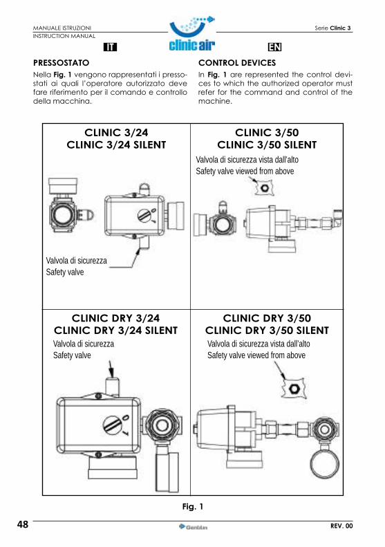
PRESSOSTATONella Fig. 1 vengono rappresentati i presso-stati ai quali l’operatore autorizzato deve fare riferimento per il comando e controllo della macchina.
CLINIC 3/24CLINIC 3/24 SILENT
CLINIC DRY 3/24CLINIC DRY 3/24 SILENT
CLINIC 3/50CLINIC 3/50 SILENT
CLINIC DRY 3/50CLINIC DRY 3/50 SILENT
INSTRUCTION MANUAL
ENCONTROL DEVICESIn Fig. 1 are represented the control devi-ces to which the authorized operator must refer for the command and control of the machine.
Valvola di sicurezzaSafety valve
Valvola di sicurezza vista dall’altoSafety valve viewed from above
Valvola di sicurezza vista dall’altoSafety valve viewed from above
Valvola di sicurezzaSafety valve

49
MANUALE ISTRUZIONI Serie Clinic 3
REV. 00
Fig. 1
CLINIC DRY 3/24 H-HSCLINIC DRY 3/24 H-HS SILENT
CLINIC DRY 3/50 H-HSCLINIC DRY 3/50 H-HS SILENT
INSTRUCTION MANUAL
Vista in piantaPlan view
Vista in piantaPlan view
Lato oppostoOpposite side
Valvola di sicurezzaSafety valve
50
IT
MANUALE ISTRUZIONI Serie Clinic 3
REV. 00
INSTRUCTION MANUAL
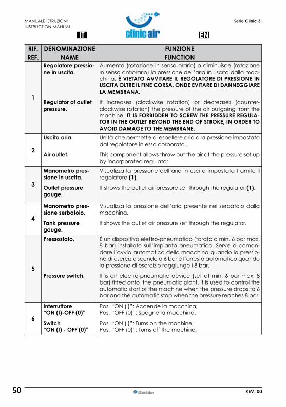
ENRIF.REF.
DENOMINAZIONENAME
FUNZIONEFUNCTION
1
Regolatore pressio-ne in uscita.
Regulator of outlet pressure.
Aumenta (rotazione in senso orario) o diminuisce (rotazione in senso antiorario) la pressione dell’aria in uscita dalla mac-china. È VIETATO AVVITARE IL REGOLATORE DI PRESSIONE IN USCITAOLTREILFINECORSA,ONDEEVITAREDIDANNEGGIARELA MEMBRANA.
It increases (clockwise rotation) or decreases (counter-clockwise rotation) the pressure of the air outgoing from the machine. IT IS FORBIDDEN TO SCREW THE PRESSURE REGULA-TORINTHEOUTLETBEYONDTHEENDOFSTROKE,INORDERTOAVOID DAMAGE TO THE MEMBRANE.
2
Uscita aria.
Air outlet.
Unità che permette di espellere aria alla pressione impostata dal regolatore in esso corporato.
This component allows throw out the air at the pressure set up by incorporated regulator.
3
Manometro pres-sione in uscita.
Outlet pressure gauge.
Visualizza la pressione dell’aria in uscita impostata tramite il regolatore(1).
It shows the outlet air pressure set through the regulator(1).
4
Manometro pres-sione serbatoio.
Tank pressure gauge.
Visualizza la pressione dell’aria presente nel serbatoio dalla macchina.
It shows the outlet air pressure set through the regulator.
5
Pressostato.
Pressureswitch.
È un dispositivo elettro-pneumatico (tarato a min. 6 bar max. 8 bar) installato sull’impianto pneumatico. Serve a coman-dare l’avvio automatico della macchina quando la pressio-ne di esercizio scende a 6 bar e l’arresto automatico quando la pressione di esercizio raggiunge i 8 bar.
It is an electro-pneumatic device (set at min. 6 bar max. 8 bar) fitted onto the pneumatic plant. It is used to control the automatic start of the machine when the pressure drops to 6 bar and the automatic stop when the pressure reaches 8 bar.
6
Interruttore“ON(I)-OFF(0)”
Switch“ON(I)-OFF(0)”
Pos. “ON (I)”: Accende la macchina;Pos. “OFF (0)”: Spegne la macchina.
Pos. “ON (I)”: Turns on the machine;Pos. “OFF (0)”: Turns off the machine.

51
IT
MANUALE ISTRUZIONI Serie Clinic 3
REV. 00
4
2
1
6
3
5
Fig. 1
7
6
5
4
3
1
2
7
INSTRUCTION MANUAL
ENRIF.REF.
DENOMINAZIONENAME
FUNZIONEFUNCTION
7
Valvola di sicurezza.
Safetyvalve.
È una valvola di sicurezza certificata (tarata a 10,5 bar), in-stallata sull’impianto pneumatico sotto al pressostato. Serve a scaricare la sovrappressione dell’impianto qualora il pres-sostato, per eventuali anomalie, non funzioni. L’intervento della valvola di sicurezza obbliga l’operatore a spegnere la macchina e richiedere l’intervento dei manutentori.ATTENZIONE! NEL MOD. CLINIC DRY 3/50 HS LA VALVOLA DI SI-CUREZZA È INSTALLATA NEL LATO OPPOSTO DEL PRESSOSTATO.
It is a certified safety valve (set at 10.5 bar), installed in the pneumatic system under the pressure switch. It is used to di-scharge the overpressure in the system if the pressure switch, for any problems, does not function.The intervention of the safety valve forces the operator to turn off the machine and request the assistance of the main-tenance technicians.ATTENTION! IN THE CLINIC DRY 3/50 HS MOD. THE SAFETY VAL-VE IS INSTALLED IN THE SIDE OPPOSITE THE PRESSURE SWITCH.

52
IT
MANUALE ISTRUZIONI Serie Clinic 3
REV. 00
CONTROLLI PRIMA DELL’ACCENSIONEPRIMA DI EFFETTUARE L’ACCENSIONE DELLA MACCHINA L’OPERATORE AD-DETTO DEVE ESEGUIRE I CONTROLLI RIPORTATI NELLA TAB. 1.
Tab. 1
12 12
2
INSTRUCTION MANUAL
ENPRIOR TO IGNITION
BEFORE TURNING ON THE MACHINE THE OPERATOR IN CHARGE MUST MAkE THE CHECkS INDICATED IN TAB. 1.
NUM.No.
CONTROLLOCONTROL
1 Assicurarsi che non vi siano persone non autorizzate nelle vicinanze della mac-china.
Make sure that no unauthorized persons are near the machine.2 Assicurarsi che la macchina sia correttamente posizionata.
Make sure the machine is properly positioned.3 Assicurarsi che tutti i collegamenti siano stati effettuati correttamente.
Make sure all connections are properly made.4 Assicurarsi che l’interruttore (2) sia in pos. “OFF (0)”.
Ensure that the switch (2) is in pos. “OFF (0)”.5 Assicurarsi che la valvola di scarico condensa sia chiusa (12).
Make sure the condensate drain valve is closed (12).6 Utilizzare i dispositivi di protezione individuale (DPI) obbligatori.
Use the Personal protective equipment (PPE) required.7 Assicurarsi di aver letto e compreso in tutte le sue parti il presente “Manuale di
Istruzioni”.
Make sure you have read and understood all parts of this “Instruction Manual”.8 Assicurarsi che dopo l’ultimo utilizzo sia stata effettuata la manutenzione ordinaria.
Make sure that after last use routine maintenance has been made.
24 LITRI/LITERS 50 LITRI/LITERS

53
IT
MANUALE ISTRUZIONI Serie Clinic 3
REV. 00
ACCENSIONE DELLA MACCHINAGLI OPERATORI AUTORIZZATI POSSO-NO ACCENDERE LA MACCHINA SOL-TANTO DOPO AVER OBBLIGATORIA-MENTE ESEGUITO I CONTROLLI DESCRITTI NELLA TABELLA DEI CON-TROLLI. PRIMA DI UTILIZZARE LA MAC-
CHINA IN OGGETTO È OBBLIGATORIO CHE GLI OPERATORI AUTORIZZATI LEGGANO E COMPRENDANO IN TUTTE LE SUE PARTI IL PRE-SENTE MANUALE. È OBBLIGATORIO TENERE LA MACCHINA FUORI DALLA PORTATA DI PERSONE NON AUTORIZZATE.
È VIETATO AGLI OPERATORI AUTORIZ-ZATI LASCIARE INCUSTODITA LA MACCHINA DURANTE GLI INTERVENTI
MANUTENTIVI.IL FABBRICANTE DECLINA OGNI RESPONSA-BILITÀPERDANNIAPERSONE,ANIMALIE/OCOSE,CAUSATIDALLAINOSSERVANZADEL-LE NORME E DELLE AVVERTENZE DESCRITTE NEL PRESENTE MANUALE.
Accendere la macchina portando l’inter-ruttore (2) in pos. “ON (I)” (la macchina fun-ziona fino a raggiungere la pressione max. di esercizio di 8 bar dopodiché si arresta automaticamente).
2
INSTRUCTION MANUAL
ENTURNING ON THE MACHINE
THE AUTHORIZED OPERATORS CAN TURN THE MACHINE ON ONLY AFTER THEY HAVE PERFORMED AS A COM-PULSORYOPERATION,THECONTROLSDESCRIBED IN THE CONTROLS TABLE BEFOREUSINGTHEMACHINEINQUE-
STION IT IS COMPULSORY THAT THE AUTHORI-ZED OPERATORS READ AND THOROUGHLY UNDERSTAND IN ALL PARTS THIS MANUAL. IT IS COMPULSORY TO kEEP THE MACHINE OUT OF REACH OF UNAUTHORIZED PERSONS.
IT IS FORBIDDEN TO THE AUTHORIZED OPERATORS TO LEAVE THE MACHINE WITHOUT SUPERVISION DURING THE
MAINTENANCE WORkS.THE MANUFACTURER HAS NO LIABILITY FOR INJURIES TO PERSONS, ANIMALS AND/ORTHINGS CAUSED BY THE INOBSERVANCE OF THE RULES AND INFORMATION DESCRIBED HEREIN.
Turn on the machine by moving the switch (2) in pos. “ON (I)” (the machine runs up to the max. operating pressure at 8 bar and then stops automatically).

54
IT
MANUALE ISTRUZIONI Serie Clinic 3
REV. 00
CLINIC 3/24CLINIC 3/24 SILENT
CLINIC DRY 3/24 H-HS CLINIC DRY 3/24 H-HS SILENT
CLINIC DRY 3/24CLINIC DRY 3/24 SILENT
CLINIC 3/50CLINIC 3/50 SILENT
CLINIC DRY 3/50 H-HSCLINIC DRY 3/50 H-HS SILENT
CLINIC DRY 3/50CLINIC DRY 3/50 SILENT
2
22 19
1922
22 22
19 19
19 22
22
19
7
REGOLAZIONE DELLA PRESSIONE IN USCITARegolare la pressione in uscita agendo sul regolatore (19) e controllando la pressione nel manometro (22).
È VIETATO AVVITARE IL REGOLATORE DIPRESSIONEINUSCITA(19)OLTREILFINECORSA,ONDEEVITAREDIDAN-
NEGGIARE LA MEMBRANA.
RESET DEL TERMICO RIPRISTINABILEQualora si verifichi un sovraccaricodi corrente e/o un cortocircuito nell’impiantoelettricodellamacchi-
na, il termico ripristinabile interviene arre-stando il motore elettrico.Pereffettuareilreset,procederecomese-gue:1)Portarel’interruttore(2)inpos.“OFF(0)”.2)Premereilpulsantedeltermicoripristina-bile(7).
3)Primadiriaccenderelamacchinaatten-derequalcheminuto.
SE DOPO AVER EFFETTUATO IL RESET LA MACCHINANONSIRIACCENDE,L’OPE-RATORE ADDETTO DEVE OBBLIGATO-
RIAMENTE RICHIEDERE L’INTERVENTO DEI MA-NUTENTORI E/O DEL RIVENDITORE AUTORIZZATO.
INSTRUCTION MANUAL
ENADJUSTING THE OUTLET PRESSUREAdjust the outlet pressure operating on the regulator (19) and by controlling the pressu-re in the pressure gauge (22).
IT IS FORBIDDEN TO TIGHTEN THE PRES-SUREREGULATORATTHEOUTLET(19)BEYONDTHEENDOFSTROKE,INOR-
DER NOT TO DAMAGE THE MEMBRANE.
RESETTABLE THERMALIfthereisanoverloadand/orashortcircuitintheelectricalsystemofthemachine,theoverloadprotectionin-
tervenesstoppingtheelectricmotor.Theresetwilloccurautomaticallywhenthetemperature returns within the parameterspresetbythemanufacturer:1)Settheswitch(2)inpos.“OFF(0)”.2)Pressthebuttonoftheresettablethermal(7).
3)Beforerestartingthemachinewaitafewminutes.
IF AFTER PERFORMING THE RESET THE MACHINE WILL NOT RESTART, THEOPERATOR IS REQUIRED TO OBTAIN
THE INTERVENTION OF MAINTENANCE TECH-NICIANS AND/OR THE AUTHORIZED DEALER.
Valvola di sicurezzaSafety valve
Vista in piantaPlan view
Vista in piantaPlan view
Lato oppostoOpposite side
Valvola di sicurezzaSafety valve
Valvola di sicurezza vista dall’altoSafety valve viewed from above
Valvola di sicurezza vista dall’altoSafety valve viewed from above

55
IT
MANUALE ISTRUZIONI Serie Clinic 3
REV. 00
SPEGNIMENTO DELLA MACCHINAA fine ciclo di lavoro effettuare lospegnimentodellamacchinacomesegue:1) Portare l’interruttore (2) in pos.
“OFF(0)”.2)Disinserire la spina del cavo di
alimentazioneelettrica(15)dallapresa e posizionarla vicino alla macchina.
3) Soloincasodifineciclolavoroeseguireloscaricocondensadalserbatoio,agen-dosullavalvoladiscaricocondensa(12).
ARRESTO EMERGENZAL’arresto di emergenza della mac-chinapuòessereeffettuatoportandoin pos. “OFF (0)” l’interruttore (2).Onde evitare situazioni di pericolo imminente o prossimo, gli operatoriautorizzati devono obbligatoriamen-
te eseguire le seguenti operazioni:
15
12 12
2
INSTRUCTION MANUAL
ENTURNING OFF THE MACHINE
Attheendoftheworkcycleperformtheturningoffofthemachineasfol-lows:1) Settheswitch(2)inpos.“OFF(0)”.
2)Unplug thepowercord (15) fromthesocketandplaceitnexttothemachine.
3) Only incaseofworkcycleendperformthecondensatedischargefromthetank,actingonthecondensatedrainvalve(12).
EMERGENCY STOPTheEmergencyStopofthemachinecanbedonebybringinginpos.“OFF(0)”theswitch(2).Toavoidsituationsof imminent danger, theAuthorizedOperatorsareobligedtoperformthefollowingoperations:
1
ESEGUIRE TEMPESTIVAMENTE LO SPEGNIMENTO DELLA MACCHINA COME DESCRIT-TO AL PARAGRAFO “SPEGNIMENTO DELLA MACCHINA”.
RUN IMMEDIATELY THE TURNING OFF OF THE MACHINE AS DESCRIBED IN PAR. “TUR-NING OFF THE MACHINE”.
2SEGNALARE IMMEDIATAMENTE L’EMERGENZA AL RESPONSABILE DEL SERVIZIO DI PREVENZIONE E PROTEZIONE (R.S.P.P.).
REPORT IMMEDIATELY THE EMERGENCY TO THE SUPERVISOR IN CHARGE.
24 LITRI/LITERS 50 LITRI/LITERS

56
IT
MANUALE ISTRUZIONI Serie Clinic 3
REV. 00
ACCENSIONE DOPO UN ARRESTO DI EMERGENZA
Solo ed esclusivamente dopo aver rimosso la causa dell’emergenza ed aver attentamente valutato che lastessa non abbia provocato danni e/oanomalieallamacchina,conilconsenso del Responsabile del ser-
viziodiprevenzioneeprotezione(R.S.P.P.)ripristinarelamacchinacomesegue:
1)Portarel’interruttore(2)inpos.“OFF(0)”.
2)Senecessario, ripetere leoperazionide-scritte al par. “ACCENSIONE MACCHINA”.
INTERVENTO VALVOLA DI SICUREZZANelcasosiverifichiunmalfunziona-mento del pressostato e la pressione all’internodelserbatoiosuperii10,5
bar, la valvola di sicurezza intervieneaprendosi meccanicamente per sfiatareall’esterno l’aria compressa e riportare la pressione al valore di sicurezza.
ALL’INTERVENTO DELLA VALVOLA DI SICUREZZA È OBBLIGATORIO SPEGNE-RE LA MACCHINA ED AVVISARE IL RE-
SPONSABILE DEL SERVIZIO DI PREVENZIONE E PROTEZIONE (R.S.P.P.) E RICHIEDERE L’ASSI-STENZA DEI MANUTENTORI O DEL RIVENDITO-RE AUTORIZZATO PER EFFETTUARE IL CON-TROLLO DEL PRESSOSTATO.
TEC3-50E
2
INSTRUCTION MANUAL
ENACTIVATION AFTER AN EMERGENCY STOP
Only after removing the cause oftheemergencyandhavingcareful-ly evaluated that the decision hasnot caused any damage and/orproblems to themachine, with theconsentoftheSupervisorincharge
restore the machine as described in thefollowingparagraph:
1)Settheswitch(2)inpos.“OFF(0)”.
2)If necessary, repeat the operations de-scribed in par. “TURNING ON THE MACHI-NE”.
INTERVENTION ON THE SAFETY VALVEIn theeventofamalfunctionof thepressureswitchandthepressureinsi-de the tank exceeds 10,5 bar, the
safety valve operates mechanically byopening for venting outside the compres-sedairandreturnthepressuretothesafetyvalue.
UPON THE INTERVENTION OF THE SA-FETY VALVE IT IS COMPULSORY TO TURNOFFTHEMACHINE,NOTIFYTHE
SUPERVISOR AND REQUEST ASSISTANCE OFMAINTENANCE TECHNICIANS OR AUTHORI-ZED DEALER TO MAkE THE CONTROL OF PRESSURE SWITCH.
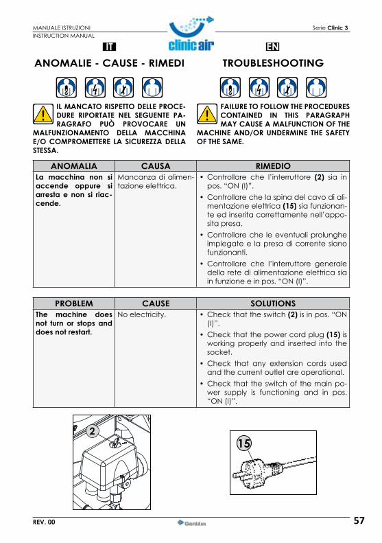
57
IT
MANUALE ISTRUZIONI Serie Clinic 3
REV. 00
ANOMALIE - CAUSE - RIMEDI
IL MANCATO RISPETTO DELLE PROCE-DURE RIPORTATE NEL SEGUENTE PA-RAGRAFO PUÒ PROVOCARE UN
MALFUNZIONAMENTO DELLA MACCHINA E/O COMPROMETTERE LA SICUREZZA DELLA STESSA.
152
ANOMALIA CAUSA RIMEDIOLa macchina non siaccende oppure si arresta e non si riac-cende.
Mancanza di alimen-tazione elettrica.
• Controllare che l’interruttore (2) sia in pos. “ON (I)”.
• Controllare che la spina del cavo di ali-mentazione elettrica(15) sia funzionan-te ed inserita correttamente nell’appo-sita presa.
• Controllare che le eventuali prolunghe impiegate e la presa di corrente siano funzionanti.
• Controllare che l’interruttore generale della rete di alimentazione elettrica sia in funzione e in pos. “ON (I)”.
INSTRUCTION MANUAL
ENTROUBLESHOOTING
FAILURE TO FOLLOW THE PROCEDURES CONTAINED IN THIS PARAGRAPH MAY CAUSE A MALFUNCTION OF THE
MACHINE AND/OR UNDERMINE THE SAFETY OF THE SAME.
PROBLEM CAUSE SOLUTIONSThe machine doesnot turn or stops and does not restart.
No electricity. • Check that the switch (2) is in pos. “ON (I)”.
• Check that the power cord plug (15) is working properly and inserted into the socket.
• Check that any extension cords used and the current outlet are operational.
• Check that the switch of the main po-wer supply is functioning and in pos. “ON (I)”.

58
IT
MANUALE ISTRUZIONI Serie Clinic 3
REV. 00
ANOMALIA CAUSA RIMEDIOLa macchina non siaccende oppure si ar-resta e non si riaccen-de.
Intervento del termico ripristinabile per so-vraccarico di corrente e/o cortocircuito.
• Eseguire la procedura descritta al par. “RESET DEL TERMICO RIPRISTINA-BILE”.
Lamacchinasi riavviapiù volte senza chel’impianto pneumatico sia in funzione.
Perdite dal tubo aria o dall’impianto pneuma-tico.
• Controllare che l’impianto pneuma-tico non abbia subito danni.
• Controllare l’integrità e i collega-menti del tubo aria e dell’impianto.
Non esce aria dal rubi-netto rapido di uscita aria.
Il serbatoio non è in pressione.
• Accendere la macchina e atten-dere il caricamento del serbatoio verificando la pressione sull’apposito manometro.
Regolazione errata della pressione in usci-ta.
• Controllare che il valore indicato nel manometro pressione in uscita (22) sia maggiore di 0 (zero) bar.
Intervento della valvo-la di sicurezza.
Pressostato guasto. Richiedere l’intervento dei manutentori o rivolgersi ad un
Rivenditore autorizzato.Perdita d’aria dallavalvola del pressostato amacchinaferma.
Valvola di ritegno spor-ca o usurata.
INSTRUCTION MANUAL
EN
PROBLEM CAUSE SOLUTIONSThemachinedoes notturn or stops and does not restart.
Intervention of the re-settable thermal due to current overload and/or short circuit.
• Follow the procedure described in par. “RESETTABLE THERMAL”.
The machine oftenstartsagainwithoutthepneumatic plant is op-erating.
Air leaks from the pipe or its pneumatic plant.
• Check that the pneumatic system is not damaged.
• Check the integrity of the pipe con-nections and air system.
Air does not flow fromthe fast valve of airoutlet.
The tank is not pressu-rized.
• Turn on the machine and wait until the tank is loaded, verifying the pres-sure on the suitable pressure gauge.
Improper adjustment of outlet pressure.
• Check that the value indicated in the pressure gauge of the output pressure (22) is greater than 0 (zero) bar.
Intervention of the sa-fetyvalve.
Faulty pressure switch. Seek the maintenance technicians or contact an Authorized Reseller.
Airleakfromthevalveof the pressure switchwithmachinestopped.
Check valve is dirty or worn.

59
IT
MANUALE ISTRUZIONI Serie Clinic 3
REV. 00
22
22
22
22
22
ANOMALIA CAUSA RIMEDIOLamacchinavibrae/o emette moltorumore.
Rottura meccanica. Richiedere l’intervento dei manutentori o rivolgersi ad un
Rivenditore autorizzato.Avviamenti frequenti ebasso rendimento.
Filtri aria sporchi.
INSTRUCTION MANUAL
EN
PROBLEM CAUSE SOLUTIONSThe machine vibratesand/or makes a lot of noise.
Mechanical failure. Seek the maintenance technicians or contact an Authorized Reseller.
Frequentstartsandlowefficiency.
Dirty air filters.

60
IT
MANUALE ISTRUZIONI Serie Clinic 3
REV. 00
È l’insieme delle attività atte a man-tenere le condizioni d’uso e funzio-namentodellamacchina,attraversovari tipi di intervento (regolazioni,controllo visivo, ripristino livelli,ecc...) eseguiti dal manutentore odal tecnico del fabbricante alla fre-quenzastabilita.
GLI OPERATORI AUTORIZZATI DEVO-NO ESEGUIRE ESCLUSIVAMENTE GLI INTERVENTI MANUTENTIVI RICHIESTI IN
BASE ALLA LORO SPECIFICA COMPETENZA PROFESSIONALE E SU CONSENSO DEL RE-SPONSABILE DEL SERVIZIO DI PREVENZIONE E PROTEZIONE .
È VIETATO AGLI OPERATORI AUTORIZ-ZATI LASCIARE INCUSTODITA LA MAC-CHINA DURANTE GLI INTERVENTI MA-
NUTENTIVI. INOLTRE DEVONO PROTEGGERE IL LUOGO DI LAVORO CON UNA CATENA BIAN-CA/ROSSA ED ESPORRE ADEGUATI AVVISI DI PERICOLO E DIVIETO PER LAVORI IN CORSO.
MANUTENZIONE
SMONTAGGIO CAPPOTTINAQualora si rendesse necessario smontare la cappottina per effettuare interventi di ispe-zione o manutenzione è sufficiente togliere le viti (A)da ambo i lati e sfilarla.
SILENT 24 SILENT 50
AA
INSTRUCTION MANUAL
EN
Thisisthesetofactivitiesdesignedtomaintain the conditions of use andoperation of the machine, throughvarioustypesofintervention(adjust-ments, visual inspection, recoverylevels,etc.)performedbythemain-tenancetechnicianorbythemanu-facturer’stechnicianatthefrequen-cyforecast.THE AUTHORIZED OPERATORS SHOULD PERFORM ONLY THE MAINTENANCE WORKS REQUIRED IN ACCORDANCE
WITH THEIR SPECIFIC PROFESSIONAL COMPE-TENCE AND UPON CONSENT OF THE SUPER-VISOR IN CHARGE.
IT IS FORBIDDEN TO AUTHORIZED OPE-RATORS TO LEAVE THE MACHINE WI-THOUT SUPERVISION DURING THE MAIN-
TENANCE WORkS. THEY SHOULD ALSO PROTECT THE PLACE OF WORk WITH A WHITE/RED CHAIN ANDEXPOSEADEQUATENOTICEOFDANGERAND PROHIBITION FOR WORkS IN PROGRESS.
MAINTENANCE
SILENT COVER DISASSEMBLYIf you need to disassemble the silent cover to do the inspection or maintenance ser-vices, you have to take out the screws (A)from both sides and remove the cover.

61
IT
MANUALE ISTRUZIONI Serie Clinic 3
REV. 00
OGNI SETTIMANA
Alterminedellagiornatalavorativa,eseguire lo scarico condensa del serbatoio, seguendo la proceduradescritta di seguito:
1)Posizionare, sotto la valvola di scaricocondensa, un contenitore di raccoltaidoneo all’uso.
2)Aprire lentamente la valvola di scaricocondensa(12)edattenderelacompletafuoriuscita di aria compressa e della con-densa.
3)Chiuderelavalvoladiscarico.
4)Riportarel’interventosullaschedadima-nutenzione.
È OBBLIGATORIO SMALTIRE IL LIQUI-DO DI CONDENSA NEL RISPETTO DELLE NORMATIVE VIGENTI NEL PAESE DI
UTILIZZAZIONE.
12 12
INSTRUCTION MANUAL
EN
PUNTO D’INTERVENTO
POINT OF INTERVENTION
SERBATOIO
TANk
TIPO D’INTERVENTO
TYPE OF INTERVENTION
SCARICO CONDENSA
CONDENSATE DRAIN
EVERY WEEk
At the end of theworkday, run thecondensate drain of the tank, fol-lowingthestepsbelow:
1)Placeunderthecondensatedrainvalve,acollectioncontainerfitforuse.
2)Slowly open the valve of condensatedrain(12)andwaitforacompleteexitofcompressed air and condensate.
3)Closethedrainvalve.
4)Indicate theactionon themaintenancecard.
YOU MUST DISPOSE OF THE CONDEN-SATIONLIQUIDINCOMPLIANCEWITHTHE REGULATIONS IN FORCE IN THE
COUNTRY OF USE.
24 LITRI/LITERS 50 LITRI/LITERS
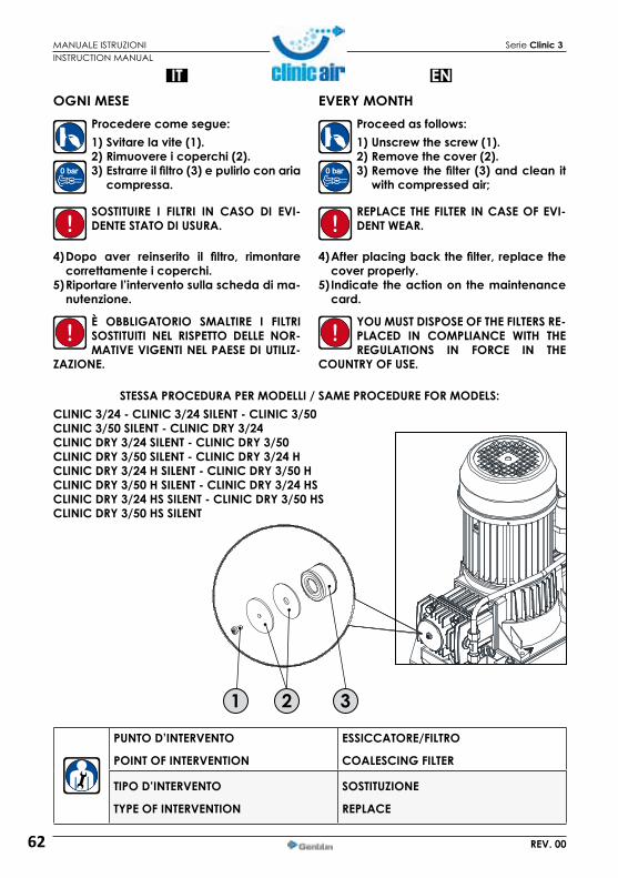
62
IT
MANUALE ISTRUZIONI Serie Clinic 3
REV. 00
1
OGNI MESEProcedere come segue:1)Svitarelavite(1).2)Rimuovereicoperchi(2).3)Estrarreilfiltro(3)epulirloconaria compressa.
SOSTITUIRE I FILTRI IN CASO DI EVI-DENTE STATO DI USURA.
4)Dopo aver reinserito il filtro, rimontarecorrettamenteicoperchi.
5)Riportarel’interventosullaschedadima-nutenzione.
È OBBLIGATORIO SMALTIRE I FILTRI SOSTITUITI NEL RISPETTO DELLE NOR-MATIVE VIGENTI NEL PAESE DI UTILIZ-
ZAZIONE.
1 2 3
INSTRUCTION MANUAL
ENEVERY MONTH
Proceedasfollows:1)Unscrewthescrew(1).2)Removethecover(2).3)Removethefilter (3)andclean it withcompressedair;
REPLACE THE FILTER IN CASE OF EVI-DENT WEAR.
4)Afterplacingbackthefilter,replacethecoverproperly.
5)Indicate theactionon themaintenancecard.
YOU MUST DISPOSE OF THE FILTERS RE-PLACED IN COMPLIANCE WITH THE REGULATIONS IN FORCE IN THE
COUNTRY OF USE.
PUNTO D’INTERVENTO
POINT OF INTERVENTION
ESSICCATORE/FILTRO
COALESCING FILTER
TIPO D’INTERVENTO
TYPE OF INTERVENTION
SOSTITUZIONE
REPLACE
STESSA PROCEDURA PER MODELLI / SAME PROCEDURE FOR MODELS:CLINIC 3/24 - CLINIC 3/24 SILENT - CLINIC 3/50 CLINIC 3/50 SILENT - CLINIC DRY 3/24 CLINIC DRY 3/24 SILENT - CLINIC DRY 3/50CLINIC DRY 3/50 SILENT - CLINIC DRY 3/24 H CLINIC DRY 3/24 H SILENT - CLINIC DRY 3/50 H CLINIC DRY 3/50 H SILENT - CLINIC DRY 3/24 HS CLINIC DRY 3/24 HS SILENT - CLINIC DRY 3/50 HS CLINIC DRY 3/50 HS SILENT

63
IT
MANUALE ISTRUZIONI Serie Clinic 3
REV. 00
CONTROLLI E MANUTENZIONE ESSICCATORE
Gli interventi di manutenzione de-vono essere eseguiti da personale qualificato.Primadiqualsiasiinter-ventoassicurarsiche:•L’essiccatorenonpresentipartiin
tensione e non possa essere ricol-legato alla rete di alimentazione elettrica.
• L’essiccatore non presenti parti in pres-sione e non possa essere ricollegato all’impianto dell’aria.
OGNI MESE• Accertare il corretto funzionamento del
sistema di scarico condensa.• Verificare il corretto funzionamento del-
l’essiccatore.
OGNI 2000 ORE• Sostituzione dei PELLETS -
KIT RIGENERANTE.• Svitare il dado (1) tenen-
do bloccato il dado (2).• Posizionare sotto l’essicca-
tore un recipiente per con-tenere i pellets da sostituire.
• Sfilare la testa superiore (3) ed estrarre il corpo (4) dalla testa inferiore (5).
• Svuotare completamente l’essiccatore dai pellets esauriti.
• Sfilare il tirante interno al corpo (4).
• Soffiare con aria com-pressa pulita corpo (4), teste (3-5), e i filtri interni all’essiccatore.
• Sostituire gli O-Ring di te-nuta sulle teste dell’essic-catore.
• Sostituire la rosetta piana in rame sul tirante dell’essic-catore e riposizionarlo in te-nuta sulla testa inferiore (5).
• Riempire il corpo (4) con i nuovi pellets.
1 3
4
25
CLINIC DRY 3/24 - CLINIC DRY 3/24 SILENT- CLINIC DRY 3/50 - CLINIC DRY 3/50 SILENT
INSTRUCTION MANUAL
EN
The maintenance interventionsmust be carried out by qualifiedstaff.Beforeanyintervention,makesurethat:•The dryer has no live parts andcannot be re-connected to themainselectricity.
• The dryer has no pressurised parts andcannotbereconnectedtotheairsystem.
EVERY MONTH• Check the correct operation of the con-
densate drain system.• Check correct operation of thedryer.
CONTROLS AND MAINTENANCE OF THE DRYER
EVERY 2000 HOURS• Replacing the PELLETS –RE-
GENERATING KIT.• Unscrew the nut (1) while
blocking the nut in (2).• Position a container under
the dryer for the pellets to be replaced.
• Slide out the upper head (3) and extract the body (4) from the lower head (5).
• Empty all waste pellets from the dryer.
• Slide out the tie-rod inside the body (4).
• Blow the body (4) heads, (3-5) and the filters inside the dryer with clean com-pressed air.
• Replace the sealing O-Rings on the dryer heads.
• Replace the flat copper washer on the dryer tie-rod and re-position it sealed on the lower head pos.5.
• Fill the body (4) with new pellets.

64
IT
MANUALE ISTRUZIONI Serie Clinic 3
REV. 00
• Riposizionare la testa superiore (3), sosti-tuire la rosetta in rame e avvitare a fondo il dado (1) tenendo bloccato il dado (2).
• Ricollegare l’ impianto.• Verificarne il corretto funzionamento, fa-
cendo attenzione alla tenuta sulle teste (3-5) sul corpo (4) dell’essiccatore.
♦ Parte di ricambio consigliata.
DFA3
1 3
4
25
RICAMBI CONSIGLIATI
INSTRUCTION MANUAL
EN• Re-position the upper head (3), replace
the copper washer and screw the nut ful-ly home (1) holding the nut (2)blocked.
• Re-connect the system.• Check the correct operation, paying at-
tention the heads are sealed (3-5) on the body (4) of the dryer.
RECOMMENDED SPARE PARTS
DESCRIZIONE DELLA PARTEDESCRIPTION OF THE PART
CODICECODE DFA3
Filtrosilenziatore/Silencerfilter 84038/1 1kit rigenerazione / Regeneration kit 84204 1♦
♦ Recommended spare parts.

65
IT
MANUALE ISTRUZIONI Serie Clinic 3
REV. 00
CLINIC DRY 3/24 HS - CLINIC DRY 3/24 HS SILENT - CLINIC DRY 3/50 HS - CLINIC DRY 3/50 HS SILENT
SerieH
SerieHS
1
2
3
4
6
9
10
8
7
5
6
9
10
8
7
5
INSTRUCTION MANUAL
EN
SOSTITUZIONE FILTRIProcedere come segue:1)Svitareidadidifissaggioallastaffa(10).
2)Sfilare l’essiccatore/filtro dallastaffa(9)esvitareipiedini(8)dalcoperchioinferiore(6).
3)Con un attrezzo idoneo, svitare le viti(1-7)edaprire i coperchi inferiore (6)esuperiore (2) dell’essiccatore/filtro (4) esostituire il filtro separatore (5)ed il filtrosterile(3).
4)Chiudereicoperchi(2-6)dell’essiccato-re/filtro(4),fissandoliconleappositeviti(Rif.1-7).
5)Avvitareipiedini(8)alcoperchioinferio-re(6)dell’essiccatore/filtro(4)edinfilarlonellastaffa(9).
6)Avvitareidadidifissaggioallastaffa(10).7)Riportarel’interventosullaschedadima-
nutenzione.
È OBBLIGATORIO SMALTIRE I FILTRI SOSTITUITI NEL RISPETTO DELLE NOR-MATIVE VIGENTI NEL PAESE DI UTILIZ-
ZAZIONE.
FILTERS REPLACEMENTProceedasfollow:1)Loosenthefixingnutsfromthebra-cket(10).
2)Slide the dryer/filter from thebra-cket (9)andunscrew the feet (8)fromthelowercover(6).
3)Usea suitable tool to loosen the screws(1-7)andopen the lowercover (6)anduppercover(2)ofthedryer/filter(4)andreplace the separator filter (5) and thesterilefilter(3).
4)Close the covers (2-6) on the dryer/fil-ter(4),fixingthemusingtheappropriatescrews(1-7).
5)Tightenthefeet(8)tothelowercover(6)ofthedryer/filter(4)andinsertitintothe-bracket(9).
6)Tightenthefixingnutstothebracket(10).7)Report the intervention on the mainte-
nance card.
IT IS MANDATORY TO DISPOSE OF THE FILTERS REPLACED IN COMPLIANCE WITH THE STANDARDS IN FORCE IN
THE COUNTRY OF USE.
Per garantire la corretta steriliz-zazionedelflussod’aria si racco-manda di sosti-tuireilfiltrosterileogni 6 mesi.Toguarantee thecorrect sterilisa-tionoftheairflow,it is recommend-edtoreplacethesterile filter every6months.
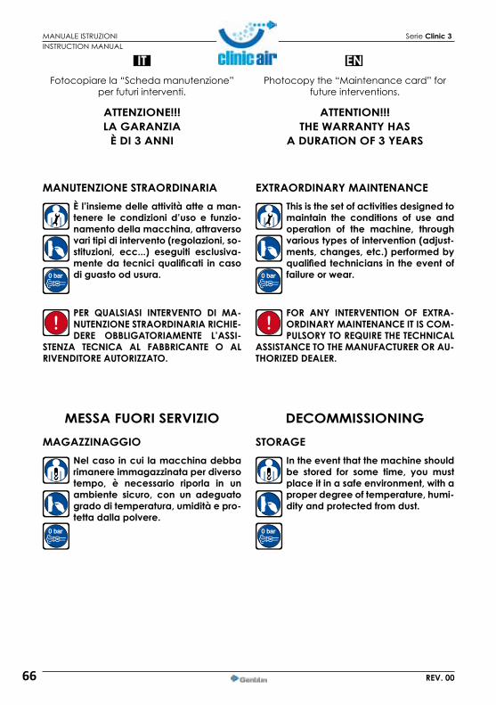
66
IT
MANUALE ISTRUZIONI Serie Clinic 3
REV. 00
Fotocopiare la “Scheda manutenzione” per futuri interventi.
ATTENZIONE!!! LA GARANZIA
È DI 3 ANNI
MANUTENZIONE STRAORDINARIAÈ l’insieme delle attività atte a man-tenere le condizioni d’uso e funzio-namentodellamacchina,attraversovaritipidiintervento(regolazioni,so-stituzioni, ecc...) eseguiti esclusiva-menteda tecniciqualificati incasodi guasto od usura.
PER QUALSIASI INTERVENTO DI MA-NUTENZIONE STRAORDINARIA RICHIE-DERE OBBLIGATORIAMENTE L’ASSI-
STENZA TECNICA AL FABBRICANTE O AL RIVENDITORE AUTORIZZATO.
MESSA FUORI SERVIZIOMAGAZZINAGGIO
Nelcasoincui lamacchinadebbarimanere immagazzinata per diverso tempo, è necessario riporla in unambiente sicuro, con un adeguatogradoditemperatura,umiditàepro-tetta dalla polvere.
INSTRUCTION MANUAL
ENPhotocopy the “Maintenance card” for
future interventions.
ATTENTION!!! THE WARRANTY HAS
A DURATION OF 3 YEARS
EXTRAORDINARYMAINTENANCEThisisthesetofactivitiesdesignedtomaintain the conditions of use andoperation of the machine, throughvarioustypesofintervention(adjust-ments,changes,etc.)performedbyqualifiedtechniciansintheeventoffailureorwear.
FOR ANY INTERVENTION OF EXTRA-ORDINARY MAINTENANCE IT IS COM-PULSORYTOREQUIRETHETECHNICAL
ASSISTANCE TO THE MANUFACTURER OR AU-THORIZED DEALER.
DECOMMISSIONINGSTORAGE
Intheeventthatthemachineshouldbe stored for some time, you mustplaceitinasafeenvironment,withaproperdegreeoftemperature,humi-dityandprotectedfromdust.

67
IT
MANUALE ISTRUZIONI Serie Clinic 3
REV. 00
DEMOLIZIONEAll’atto della demolizione della macchina, attenersi obbligatoria-mente alle prescrizioni vigenti nel paese di demolizione. Procedere alla differenziazione delle parti checostituisconolamacchinasecondoidiversi tipi di materiali di costruzione (plastica,rame,ferro,ecc…).
Questiprodotticonsideratiinquinantie pericolosi vanno obbligatoriamen-te smaltiti incaricando ditte autoriz-
zate e specializzate per le differenti tipolo-gie di prodotto.
TUTTI I COMPONENTI DELLA MACCHI-NA VANNO OBBLIGATORIAMENTE IDENTIFICATI SECONDO LE DEFINIZIO-
NIDEI“CODICICER”(CATALOGOEUROPEORIFIUTI)ESMALTITIINCARICANDODITTEAU-TORIZZATEESPECIALIZZATE,NELL’ASSOLUTORISPETTO DELLE NORMATIVE VIGENTI NEL PA-ESE DI DEMOLIZIONE DELLA MACCHINA.
I RIFIUTI DI APPARECCHIATURE ELET-TRICHE ED ELETTRONICHE (RAEE)VANNO SMALTITI NELL’ASSOLUTO RI-SPETTO DELLE NORMATIVE VIGENTI
NEL PAESE DI DEMOLIZIONE DELLA MACCHI-NA.
RICAMBII RICAMBI ORIGINALI PER EVENTUALI SOSTITUZIONI VANNO RICHIESTI ESCLUSIVAMENTE AL FABBRICANTE.È ASSOLUTAMENTE VIETATO L’UTILIZZO DI RICAMBI NON ORIGINALI.
ALLEGATISCHEDE TECNICHE DELL’ESSICCATORE/FILTRONelle pagine seguenti vengono riportate le schede tecniche relative all’essiccatore/filtro.
INSTRUCTION MANUAL
ENDEMOLITION
Upon demolition of the machine,strictly follow the requirements inforceinthecountryofdemolition.Proceed to thedifferentiationof thepartsthatmakeupthemachineac-cordingtothedifferenttypesofcon-structionmaterials(plastics,copper,iron,etc....).
Theseproductsmustbeconsideredpollutants and hazardous charginglicensed contractors and disposed
ofbyappointingspecializedcompaniesfordifferenttypesofproducts.
ALL PARTS OF THE MACHINE MUST BE IDENTIFIED ACCORDING TO THE DEFI-NITIONS OF “CER CODES” (EUROPE-
ANWASTECATALOGUE)ANDDISPOSEDOFBY INSTRUCTING AUTHORIZED AND SPECIALI-ZED COMPANIES, IN STRICT COMPLIANCEWITH THE REGULATIONS IN FORCE IN THE COUNTRY OF DEMOLITION OF THE MACHINE.
WASTES OF ELECTRICAL AND ELEC-TRONIC EQUIPMENT (RAEE) MUST BEDISPOSED OF IN STRICT COMPLIANCE WITH THE REGULATIONS IN FORCE IN
THE COUNTRY FOR THE DEMOLITION OF THE MACHINE.
SPARE PARTS GENUINE PARTS FOR ANY SUBSTITU-TIONS MUST BE REQUIRED ONLY TOTHE MANUFACTURER.IT IS STRICTLY PROHIBITED THE USE OF NON ORIGINAL SPARE PARTS.
ATTACHMENTSDRYER/FILTER TECHNICAL SHEETSThe following pages will give the technical she-ets relative to the dryer/filter.

68
IT
MANUALE ISTRUZIONI Serie Clinic 3
REV. 00
SCHEDA TECNICA DRYTECL’essicatore a membrana DRY TEC raggruppa in un unico blocco tutti i seguenti organi:• Elemento filtrante ÷ separatore di condensa,
alloggiato nella testata inferiore d’ingresso aria compressa. La sua funzione è quella di sepa-rare la fase liquida di condensa, per così con-vogliare la sola fase di vapore acqueo verso il nucleo delle membrane a fibre cave.
• Dispositivo antipulsatorio: questo è intelligen-temente alloggiato all’interno del filtro stesso e ha per funzione quella di smorzare il flusso pulsatorio pertinente al moto dei compressori a pistoni, salvaguardando così le fibre da uno stress indesiderabile.
• Scaricatore automatico della condensa: nes-sun compromesso è concesso: trattasi di un vero scaricatore a galleggiante che scarica in funzione dell’innalzamento del livello della condensa e non di un dispositivo parziale che possa scaricare solo a fine pompata.
• Nucleo disidratatore: questo è costituito da una fascio di membrane a fibre cave, la cui carat-teristica è quella di diffondere, ovvero cedere l’umidità verso l’esterno, attraverso una parete porosa caratterizzata da un cosiddetto taglio molecolare selettivo che consente la migrazio-ne della sola molecola di vapor acqueo, men-tre le molecole di azoto e ossigeno costituenti il flusso d’aria rimangono all’interno del tubo capillare.
• Ugello di rigenerazione intercettato: al fine di fa-vorire l’estrazione dell’umidità “pompata” attra-verso la parete porosa, una percentuale (~10%) d’aria secca viene espansa attraverso un ugello che fa defluire questa corrente di rigenerazione in contro-flusso sul lato esterno delle membrane a fibre intrecciate. Flessibile e razionale: in fun-zione della grandezza del compressore, l’ugello può essere cambiato in modo che una unica membrana copra l’intera gamma di portate (nominalmente da 100 e 150 NI/min), ad ogni modo ottimizzabile in funzione delle proprie esi-genze del Costruttore).
• Filtrobattericida(opzione): la testata di uscita è già predisposta per alloggiare un elemento filtrante asettico. Lo si propone in opzione in modo da non aggravare il costo primo delle apparecchiature destinate a mercati più po-veri, cosicché altrettanto soddisfare senza ul-teriori trasformazioni le esigenze della clientela più rigorosa. I componenti di questo elemento sterile sono in accordo a quanto regolamenta-to dalla normativa FDA (Food Drug Administra-tion) ed è sterilizzabile in autoclave secondo criteri convenzionali.
GENTILINSRLTechnicaldept.
INSTRUCTION MANUAL
ENDRYTEC TECHNICAL SHEETTheDRY TECmembranedryercollectsall of thefollowingpartsinauniqueblock:• Filteringelement÷condensateseparator, hou-
sed in thelower compressed air input head. Its function is to separate the condensate liquid phase and then convey just the water vapour phase towards the cores of the hollow fibre membranes.
• Anti-pulse device: this is intelligently housed in-side the filter itself and dampens the pulse flow pertinent to the movement of the piston com-pressors, thus protecting the fibres from undesi-rable stress.
• Automatic condensate drain: no compro-mise is allowed: it is a real float drain that operates depending on the rising level of condensate and not of a partial device that can only drain at the end of pumping.
• Coredehydrator:this is made up from a bundle of hollow fibre membranes, whose characte-ristic is that of distributing, i.e. transferring the humidity towards the outside, through a porous wall characterised by a so-called selective mo-lecular size, which allows migration just of the water vapour molecule, while the molecules of nitrogen and oxygen making up the air flow re-main inside the capillary tube.
• Regeneration nozzle cut-off: in order to favour the extraction of the humidity “pumped” throu-gh theporous wall, a percentage (~10 %) of dry air is expanded through a nozzle, which ma-kes this regeneration current flow in backflow mode on the external side of the intertwined fibre membranes. Flexible and rational: depen-ding on the size of the compressor, the nozzle can be changed so that a unique membrane covers the entire range of flow rates (nominally from 100 and 150 NI/min, which can be opti-mised depending on customer requirements).
• Anti-bacterialfilter(option):the output head is already set-up to house an anti-septic filtering element. It is offered as an optional so as not to increase the purchase cost of the equipment is not needed, so as to satisfy the more deman-ding customer without further transformations. The components of this sterile element are in compliance with that governed by the FDA Standard (Food and Drug Administration) and can be sterilised in autoclave according to conventional criteria.
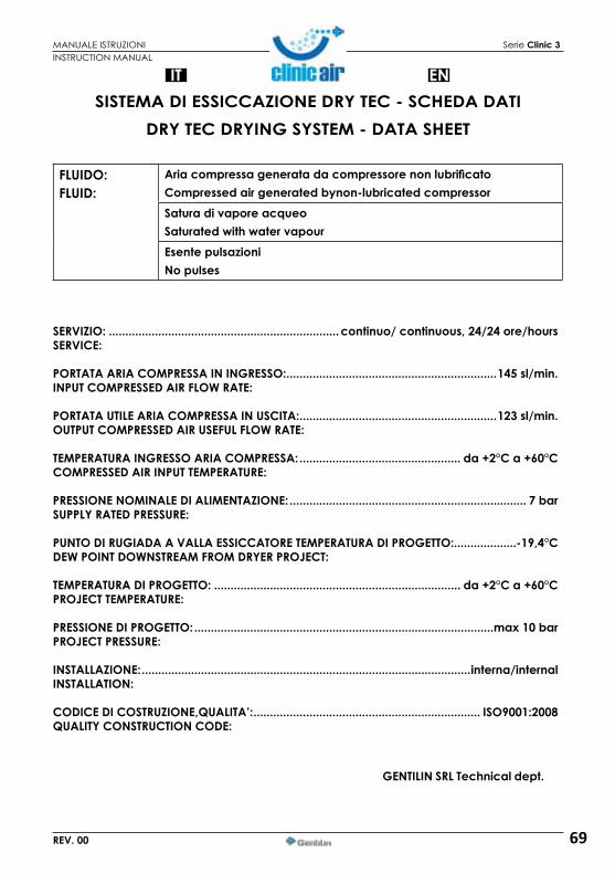
69
IT
MANUALE ISTRUZIONI Serie Clinic 3
REV. 00
INSTRUCTION MANUAL
ENSISTEMA DI ESSICCAZIONE DRY TEC - SCHEDA DATI
DRY TEC DRYING SYSTEM - DATA SHEET
SERVIZIO: ......................................................................continuo/continuous,24/24ore/hoursSERVICE:
PORTATA ARIA COMPRESSA IN INGRESSO: ................................................................145 sl/min.INPUT COMPRESSED AIR FLOW RATE:
PORTATA UTILE ARIA COMPRESSA IN USCITA: ............................................................123 sl/min.OUTPUT COMPRESSED AIR USEFUL FLOW RATE:
TEMPERATURA INGRESSO ARIA COMPRESSA: ................................................. da +2°C a +60°CCOMPRESSED AIR INPUT TEMPERATURE:
PRESSIONE NOMINALE DI ALIMENTAZIONE: ........................................................................ 7 barSUPPLY RATED PRESSURE:
PUNTO DI RUGIADA A VALLA ESSICCATORE TEMPERATURA DI PROGETTO:...................-19,4°CDEW POINT DOWNSTREAM FROM DRYER PROJECT:
TEMPERATURA DI PROGETTO: ........................................................................... da +2°C a +60°CPROJECT TEMPERATURE:
PRESSIONE DI PROGETTO: ...........................................................................................max10barPROJECT PRESSURE:
INSTALLAZIONE: ....................................................................................................interna/internalINSTALLATION:
CODICEDICOSTRUZIONE,QUALITA’: ..................................................................... ISO9001:2008QUALITYCONSTRUCTIONCODE:
FLUIDO:FLUID:
AriacompressageneratadacompressorenonlubrificatoCompressedairgeneratedbynon-lubricatedcompressorSaturadivaporeacqueoSaturatedwithwatervapourEsente pulsazioniNo pulses
GENTILINSRLTechnicaldept.

70
MANUALE ISTRUZIONI Serie Clinic 3
REV. 00
TECNOLOGIA INNOVATIVA PULITA
ETHAFILTER s.r.l. Via Dell’Artigianato, 16/18 I-36050 Sovizzo (Vicenza) Italia Tel. + 39 / 0444 376402 Fax +39 / 0444 376415 e-mail: [email protected]
CERTIFICATO di CONFORMITÀ ELEMENTO FILTRANTE
Modello: EDT 4869 FF3
Questi elementi filtranti sono prodotti d’altissima qualità ed assicurano il grado di filtrazione richiesto per aria e gas tecnici compressi. I materiali con i quali è costruito l’elemento filtrante sono:
Testate: POM / Acciaio Inox / Alluminio / PETP ( a seconda modello) Cilindro interno/esterno: lamiera d'acciaio inossidabile stirata e spianata Strato protettivo interno/esterno: superbonded PES / fibra di vetro Strato filtrante ad alta efficienza: “sandwich" di profondità in micro fibra di vetro borosilicato
(per CA-CAS: sandwich micro fibra di vetro borosilicato impregnato di carbone attivo) Calza drenante (se presente; non per RD) feltro di poliestere agugliato / schiumato colorato Sigillante: poliuretano bi-componente
PRESTAZIONI DELL’ELEMENTO FILTRANTE:
L’elemento filtrante grarantisce le seguenti prestazioni, in base al suo il grado di filtrazione:
ATTENZIONE !!
- Non utilizzare l’elemento al di fuori dei limiti consentiti imposti dalla tabella. - Sostituire l’elemento filtrante quando siano raggiunti i limiti di pressione differenziale e/o di ore di utilizzo. - Solo personale competente ed addestrato può svolgere operazioni di installazione, manutenzione, sostituzione
degli elementi filtranti. - Non togliete o sostituite alcun elemento dal contenitore quando questo si trova in pressione.
GRADO FILTRAZIONE WS VF25
RD 25 FF5 RD5
FF3 VF3 RD3
MFO FF1 RD1
SMA SMFO RDA
SMAA CA CAS
Rimozione particellare n.a. 25 µ 5 µ 3 µ 1 µ 0,01 µ 0,01 µ 0,01 µ
Residuo di olio (a 20°C) 30 mg/m3 10 mg/m3 5 mg/m3 3 mg/m3 0,1 mg/m3 0,01 mg/m3 0,001 mg/m3 0,005 mg/m3
Classe qualità ISO 8573-1 per max particelle solide n.a. 4 3 3 2 1 1 1
Classe qualità ISO 8573-1 per max contenuto olio n.a. n.a. 4 4 2 1 1 1
∆p iniziale ⇒ pulito, asciutto n.a. 30 mbar 40 mbar 50 mbar 75 mbar 100 mbar 100 mbar 75/150 mbar
∆p iniziale ⇒ “saturo” (non per RD)
70 mbar 50 mbar 75 mbar 100 mbar 150 mbar 300 mbar 300 mbar n.a.
∆p max. ⇒ cambio elemento n.a. 350 mbar 4-6 mesi
Max temperatura ammissibile ≤ 70°C 120° C ( ≤60 °C se con calza drenante schiumata) ≤ 50°C ≤ 25°C
per i gradi WS, VF, FF, MFO, SMFO, SMA, CA, CAS ⇒ dall'interno verso l'esterno Direzione del flusso
per tutti i gradi RD ⇒ dall'esterno verso l'interno
ITINSTRUCTION MANUAL

71
MANUALE ISTRUZIONI Serie Clinic 3
REV. 00
INNOVATIVE CLEAN TECHNOLOGY
ETHAFILTER s.r.l. Via Dell’Artigianato, 16/18 I-36050 Sovizzo (Vicenza) Italia Tel. + 39 / 0444 376402 Fax +39 / 0444 376415 e-mail: [email protected]
CERTIFICATE of CONFORMITY FILTER ELEMENT
Model: EDT 4869 FF3
These filter elements are manufactured to the highest quality standards to ensure the best performance and reliability. Materials of construction are as follows:
End Caps POM / Stainless steel / Alluminum / PETP Inner and outer cylinder: stretched perforated stainless steel First / Final Filtration Layer: superbonded PES or fiber glass High Efficiency Filtration layer: borosilicate glass microfibre depth “sandwich”
(CA-CAS: depth “sandwich” made of borosilicate glassmicrofibreimpregnated by sinter activated carbon ) Drainage Layer (if fitted; not for RD) polyester needle felt or coloured foam Potting two part polyurethane
FILTER ELEMENT PERFORMANCE:
The filter element guarantees following performances based on its filtering grade:
IMPORTANT NOTE:
- Do not use the element out of the limits declared in the above table. - Once differential pressure limits/or usage hours would be achived,filter element should be replaced. - Only competent personnel is allowed to install,make maintenance or replace filter elements - It’s forbidden to move or to replace any filter element from the filter housing under pressure.
FILTER GRADE WS VF25 RD 25
FF5 RD5
FF3 VF3 RD3
MFO FF1 RD1
SMA SMFO RDA
SMAA CA CAS
Max particle size n.a. 25 µ 5 µ 3 µ 1 µ 0,01 µ 0,01 µ 0,01 µ
Max oil content (@20°C) 30 mg/m3 10 mg/m3 5 mg/m3 3 mg/m3 0,1 mg/m3 0,01 mg/m3 0,001 mg/m3 0,005 mg/m3
ISO 8573-1 Class Solid particles
n.a. 4 3 3 2 1 1 1
ISO 8573-1 Class Max oil content
n.a. n.a. 4 4 2 1 1 1
Initial ∆p ⇒ clean and dry n.a. 30 mbar 40 mbar 50 mbar 75 mbar 100 mbar 100 mbar 75/150 mbar
Initial ∆p ⇒ saturated (not for RD grade)
70 mbar 50 mbar 75 mbar 100 mbar 150 mbar 300 mbar 300 mbar n.a.
∆p max. ⇒ change of element n.a. 350 mbar 4-6 month
Max allowable temperature ≤ 70°C 120° C ( ≤60 °C with foam drainage layer) ≤ 50°C ≤ 25°C
grades WS, VF, FF, MFO, SMFO, SMA, CA, CAS ⇒ from inside to outside Flow direction
for every RD grade ⇒ from outside to inside
INSTRUCTION MANUAL
EN

72
MANUALE ISTRUZIONI Serie Clinic 3
REV. 00
TECNOLOGIA INNOVATIVA PULITA
ETHAFILTER s.r.l. Via Dell’Artigianato, 16/18 I-36050 Sovizzo (Vicenza) Italia Tel. + 39 / 0444 376402 Fax +39 / 0444 376415 e-mail: [email protected]
CERTIFICATO di CONFORMITÀ ELEMENTO FILTRANTE STERILE
Modello: EDT 5635ST
Questi elementi filtranti asettici sono prodotti d’altissima qualità ed assicurano il grado sterile richiesto nell’alimentazione d’aria e gas compressi.
I materiali con i quali è costruito l’elemento filtrante sono: Testate: acciaio inox AISI 304 oppure PETP (materiale sintentico conforme F.D.A.) Cilindro interno/esterno: acciaio inox AISI 304 Strato protettivo interno/esterno: tessuto di vetro Strato filtrante ad alta efficienza: “sandwich" di profondità in micro fibra di vetro borosilicato Sigillante: composto siliconico, per alte temperature, composizione secondo norme F.D.A. O-ring: composto siliconico per alte temperature, composizione secondo norme F.D.A.
Il media filtrante ad alta efficienza è composto da micro fibre di vetro borosilicato grado HEPA certificato, avente una penetrazione inferiore a 0.0001 % @ 0.3 µ, equivalente ad un’efficienza assoluta di > 0.3 µ se testato con aerosol DOP e misurato con contatore di particelle. Il sigillante, se riscaldato, rimane flessibile, in modo da permettere un’espansione delle parti metalliche durante la sterilizzazione. N.B.: Chi utilizza l’elemento filtrante è responsabile nell’assicurare che sia rispettato il corretto processo d’inibizione della
crescita dei batteri e dei virus fermati dall’elemento. È comunque consigliato sterilizzare il filtro prima di ogni sequenza di lavoro asettico. Questi elementi possono essere sterilizzati a 120 °C in autoclave per 20/30 minuti (50 fasi massimo eseguibili).. Per una sterilizzazione a vapore “in situ”, è necessario bilanciare la condizione del vapore tramite un piccolo orifizio direzionato dall’esterno all’interno del filtro. Dopo la sterilizzazione a vapore, e prima di iniziare il processo in gas, è necessario lasciare ad asciugare il filtro. Al fine di garantire una maggiore durata del filtro, è consigliato verificarne occasionalmente l’integrità. Nel caso in cui non siano disponibili le attrezzature per la verifica, è consigliato sostituire l’elemento filtrante ogni 6 mesi.
PRESTAZIONI DELL’ELEMENTO FILTRANTE: Grado di filtrazione 0,01 µ
Temperatura max. 200 °C Temperatura max. di sterilizzazione: 138 °C (secondo BS3970, part 3, cycle A) Caduta di pressione iniziale 150 mbar Cambio elemento filtrante 400 mbar
ATTENZIONE !! - Prima di installare l’elemento filtrante, assicurarsi che l’o-ring ed il contenitore siano puliti e lubrificati con
olio siliconico approvato dal F.D.A. (Food and Drug Administration). - Sostituire l’elemento filtrante quando siano raggiunti i limiti di pressione differenziale e/o di ore di utilizzo. - Solo personale competente ed addestrato può svolgere operazioni di installazione, manutenzione, sostituzione
degli elementi filtranti. - Non togliete o sostituite alcun elemento dal contenitore quando questo si trova in pressione.
ITINSTRUCTION MANUAL

73
MANUALE ISTRUZIONI Serie Clinic 3
REV. 00
INNOVATIVE CLEAN TECHNOLOGY
ETHAFILTER s.r.l. Via Dell’Artigianato, 16/18 I-36050 Sovizzo (Vicenza) Italia Tel. + 39 / 0444 376402 Fax +39 / 0444 376415 e-mail: [email protected]
CERTIFICATE of CONFORMITY STERILE FILTER ELEMENT
Model: EDT 5635SR
These aseptic class filter elements are produced to the highest quality standards to ensure the requirements of sterile degree in compressed air and gas feed.
Materials of construction are as follows: Endcaps: AISI 304 grade stainless steel or FDA allowed white sintetic material Inner and outer cylinder: expanded AISI 304 grade stainless steel High Efficiency Filtration layer: "depth sandwich" of borosilicate glass micro fibre Sealant: white silicone compound, selected for resistance to high temperature, composition in accordance with F.D.A. recommendations. O-ring: high temperature silicone compound, composition in accordance with F.D.A. recommendations.
The high efficiency filter media is made of certified HEPA grade borosilicate glass microfibre, having a penetration of less than 0.0001% at 0.3 µ., equivalent to an overall efficiency ≥ 0.3 µ when tested with a DOP aerosol and measured with a nucleus condensate particle counter. Sealant remains flexible when warming-up, in order to compensate for metal parts expansion during sterilisation. N.B.: It is User's responsibility to ensure that a suitable process for inhibiting growth of trapped bacteria and virus is respected. It
is therefore recommended to sterilise the filter prior commencement of each sequence of aseptic duty. These elements are capable of withstanding sterilisation phases of 20 ÷ 30 minutes in autoclave at 120 °C (50 steps maximum executable). For "in situ" steam sterilisation, conventional steam condition for this purpose should be balanced across filter element with a small flow orifice directed from outside to in. After steam sterilisation, the element should be allowed to flash dry before the process gas is turned on. For maximum service life, it is recommended to check from time to time filter integrity. In case testing equipment is not available, it is suggested to replace the filter element every six calendar months.
FILTER ELEMENT SPECIFICATION: Filter grade 0.01 µ
Max. temperature 200 °C Max. sterilising temperature 138 °C (as per BS3970, part 3, cycle A) Initial pressure drop, clean and dry 150 mbar Change filter element 400 mbar
IMPORTANT NOTE:
- Before replacing the filter element, make sure that the o-ring and the housing are clean and lubricated with silicon compatible oil approved by F.D.A. (Food and Drug Administration)
- Once differential pressure limits or working hours are reached, filter element must be replaced. - Only competent Personnel is allowed to install, perform maintenance or replace filter elements. - It’s forbidden to move or to replace any filter element from the filter housing under pressure.
INSTRUCTION MANUAL
EN

74
IT
MANUALE ISTRUZIONI Serie Clinic 3
REV. 00
SCHEDA MANUTENZIONE
INSTRUCTION MANUAL
ENMAINTENANCE SCHEDULE
CLINIC 3/24 - CLINIC 3/50 - CLINIC 3/24 SILENT - CLINIC 3/50 SILENT
Descrizione/Description Codice/CodeGTAF 20-X83045/18403984053/183200
500
1000
1500
2000
2500
3000
3500
4000
4500
5000

75
IT
MANUALE ISTRUZIONI Serie Clinic 3
REV. 00
SCHEDA MANUTENZIONE
INSTRUCTION MANUAL
ENMAINTENANCE SCHEDULE
CLINIC DRY 3/24 - CLINIC DRY 3/50 - CLINIC DRY 3/24 SILENT - CLINIC DRY 3/50 SILENT
Descrizione/Description Codice/CodeGTAF 20-X83045/18403984053/183200
500
1000
1500
2000
2500
3000
3500
4000
4500
5000

76
IT
MANUALE ISTRUZIONI Serie Clinic 3
REV. 00
SCHEDA MANUTENZIONE
INSTRUCTION MANUAL
ENMAINTENANCE SCHEDULE
Pergarantirelacorrettasterilizzazionedelflussod’ariasiraccomandadisostituire ilfiltrosterileogni6mesi(Cod.84023).
Toguaranteethecorrectsterilisationoftheairflow,itisrecommendedtoreplacethe sterilefilterevery6months(Cod.84023).
CLINIC DRY 3/24 H e HS - CLINIC DRY 3/50 H e HS - CLINIC DRY 3/24 H e HS SILENT - CLINIC DRY 3/50 H e HS SILENT
Descrizione/Description Codice/CodeGTAF 20-X83045/18403984053/183200
500
1000
1500
2000
2500
3000
3500
4000
4500
5000


GENTILIN SRLVia delle Tezze, 20/22
36070 Trissino (VI) ITALYTel. +39 0445 962000Fax+390445491412
CLINIC AIR [email protected]
MA
N.C
LIN
IC3
IT-E
N R
ev.0
0