Embed Size (px)
Citation preview

599 | P a g e
TRANSIENT STRUCTURAL ANALYSIS OF A SINGLE
CYLINDER 4 STROKE PETROL ENGINE
CRANKSHAFT
R. Jagadeesh Kumar1, K. Phaniteja
2, K. Sambasiva Rao
3
1P.G Student,
2P.G Student, Assistant professor and Project guide
3
Department of Mechanical Engineering, Swamy Vivekananda Engineering College, (India)
ABSTRACT
The crankshaft is a machine member which converts the reciprocating motion into rotating motion or vice
versa. The fatigue strength of the crankshafts is increased by changing the radius at the ends of each main and
crankpin bearing. The radius itself reduces the stress in these critical areas (generally at weak cross sections
like crank pin). The shaft is subjected to various forces but usually needs to be analyzed in two cases. The first
reason is failure occurs at the crank pin where the maximum bending due to maximum gas pressure. Second
reason, crank may fail due to twisting moment. In the current paper, the strength of a single cylinder crankshaft
is evaluated for the various crank pin radii and for the two different alternative materials is evaluated. The 3D
CAD model will be generated by using commercial modeling software such as CATIA v5 and the numerical
models will be prepared using HYPERMESHv11. These models will be solved using ANSYS v16.1.
Keywords: ANASYS v16.1, CATIA V5, HYPERMESH v11, Maximum Bending and Maximum
Twisting etc.
I. INTRODUCTION
The crankshaft must oppose the bending stresses caused by connecting rod thrust when the engine piston is at
the top dead centre position. Then the maximum gas pressure acts directly on the crank pin and tends to deform
the shaft and its adjacent bearings. The crankshaft have to be withstand the torsional forces which produced by
change of speed with respect to the time.
The development of design mainly depends on the bending load, shear load and combined loads. This
consideration may be differs for different materials because of difference in material density that means varies
with respect to the weight of the crankshaft. In this paper the change of weight can be varies in two ways one is
by altering the radius of the crank pin and second one is changing the material, in order to produce a less
expensive component with the lowest amount of weight possible and the proper fatigue strength and other
functional requirements. These improvements gives better results like lighter and smaller engines with better
analysis before starts the working of the engine where loads acting on the engine while altering the time that
means transient loads.

600 | P a g e
The main objective of this project is to comparative study of the structural steel and ductile cast iron crankshafts
from similar engines were studied in this paper. The finite element analysis was performed in number of
iterations by altering different materials under different crank pin radius of crankshaft. The Stresses from these
analyses were used for analyzing the optimized crank shaft regards to dynamic loading. By changing the
material we can obtain optimized material to prepare crankshaft that means lesser in cost without affecting the
structural properties.
II. LITERATURE REVIEW
This survey used to enhance the project, where we can compare this paper work with already existing one. I was
studied no of papers , this survey gives me an idea to start working on the transient structural analysis on the
four stroke petrol engine crankshaft. The following report shows that different theories or papers which already
done on crankshaft analysis.
2.1 Operating Conditions & Failures of Crankshafts
A broad review on crankshafts was done by Zoroufi and Fatemi in the year 2015. Their study explains or
focused on fatigue performance evaluation and comparisons of crankshafts (forged steel and ductile cast iron).
Also they study the crankshaft specifications, various failures and causes of failure and the operating
conditions.In 2003, a publisher named as Silva classifies the causes of journal bearing failures into three
possible sources. (i) Operated sources like lack of sufficient oil, improper lubrication of journal bearing, high oil
temperature and improper usage of engine. (ii) Mechanical related sources such as misalignment of the
crankshaft assembly, inappropriate journal bearings may be wrong in size, lack proper clearance or lack of
minimum oil film thickness (ho) between journal and bearing (may be improper finishing process such as
grinding), vibrations in crankshaft etc. (iii) misalignment sources such as improper alignment of the crankshaft
due to improper misalignment assembly of the crankshaft , high stress concentration factor, more surface
roughness (improper production process), miss alignment due to wear and tear, strengthening operation etc are
discussed by Silva.
2.2. Determination of dynamic loading and Analysis Techniques
In the year 1970, Jenson conducted an experimental study to determine the loads applied on crankshaft. The
determination of the load in this study started with the selection of the crankshaft sections to be investigated. In
the year 1992, Henry et al. developed the dynamic load in their Finite Elements Methods (FEM) model by
considering the external bearing loads, torsional dynamic loads and internal centrifugal loads. In their study,
internal loads (centrifugal effect) were calculated by assuming constant mass matrix. Therefore for any speed of
the engine, the resulting displacements were calculated only once. They also consider external bearing loads like
gas pressure and inertial forces on the bearing. In the year 1998 Prakash et al. used the both advantages of the
traditional method and finite element methods techniques in their studies to design crankshafts. They used the
traditional or classical method in order to determine the initial and the approximate results, based on this results

601 | P a g e
they were developed a program TVAL, which is used to know the natural frequencies quickly. Also to know the
critical modes, displacement, stresses and strain energy.
2.3. Finite Element Methods
In the year 1984, Uchida and Hara used a single throw FEM model to extrapolation of the experimental equation
in their investigation. Also they study the crank web thickness of 600 V6 crankshaft was reduced while
maintaining its fatigue performance and durability under turbo charged gas pressure. Also they studied about
engine crankshaft dimensions, the vol mises stress elevation of the crankpin fillet radius at extremely critical
stage, to reduce the crank shaft length, it was necessary to reduce the thickness of the web between journal and
crankpin to reduce failure correspondingly increased the overall strength of the assembly. There are no of
theoretical studies also conducted through experiments results on the Guagliano (1993) was conducted few
experiments to calculate the stress concentrate factor for a diesel engine crankshaft. They also conducted no of
experimental tests by mounting strain gauges where high stress concentration occurs in the geometry of the
engine crankshaft i.e at crank fillets.
III. SELECTION OF SUITABLE ANALYSIS TECHNIQUE
In any production industries there is a need of quality and desired standards for every type of component that
means output production. To know the performance or standards of the component it is required to do some
destruction and non destruction tests. Now days it is necessary to know the standards and failure criteria of the
components before starting the production. For that there are several analysis techniques are available to
understand the concept or behavior of the components under several boundary conditions.
3.1 Structural Analysis
It is the most probable and common application of the finite element method. The term structural not only
related to the civil engineering applications such buildings, bridges. Also it can be applicable in navel,
aeronautical and other mechanical structures such as machine parts (pistons, cylinders, crankshaft, gearbox etc)
and other machine tools. There are so many types of analysis techniques available such as static analysis, modal
analysis, harmonic analysis, transient dynamic analysis, spectrum analysis and buckling analysis. Among all
structural analysis the transient analysis is suitable technique to analyze the given crankshaft because the loads
acting on the crankshaft varies with effect of the time. The mass of the component is to be considered while
accelerating forces are acting the crankshaft. Because of the load acting on the engine crankshaft also causes
vibrations such that it is necessary to consider damping effect along with time.’
3.2. Transient Analysis
The transient analysis is a techniques used to find out the dynamic reaction of the entire structure under the
action of loads or forces by time dependent factor. So it is also known as time history analysis.

602 | P a g e
Using this technique we can find displacements, stresses, strains, and other forces within the structure under the
action of time dependent force vector. It is a combined effect of damped loads, mass effect on the structure also
displacement vector on the given body. Sometimes it is a derived application of modal analysis.
The basic equitation for transient analysis is
(1)
Where,
[M] is the non linear mass matrix,
[D] is the non linear damping matrix,
[C] is the stiffness matrix,
is the accelerating vector,
is the velocity vector,
is the displacement vector and
F(t) is the force vector with respect of time.
3.2.1. There Are Mainly Two Types of Transient Analysis
Implicit Analysis - Implicit method is more efficient for relatively slow running events.
Explicit Analysis - Explicit method is more efficient and capable for very fast events, such as impact and
explosion forces.
IV. METHODOLOGY
In this chapter, the procedure or experimentation can be explained to determine the various unknown parameters
for the given petrol engine crankshaft. For that, taking one case of solving the problem (that means taking
structural steel at 5mm crankpin radius). The following are the basic steps needed to obtain the solution or
results.
The following are the main important steps to determine the unknown parameters such as deformation, Von
Mises Stress, 1st principal stress, 3rd principal stress for different materials and different geometrical shapes
(Crankpin radius).

603 | P a g e
4.1. Identifying the Problem
This is the basic important step for solving or determining or designing the any problem in the engineering field.
It is necessary to identify the problems in the given structure to develop the new design by minimizing those
problems. In this project the following explanation will gives us the problem identification.
It is typically connected to a flywheel to reduce the thump characteristic of the 4-stroke cycle, and sometimes a
torsional or vibrational damper at the opposite end, to reduce the torsional vibrations often caused along the
length of the crankshaft by the cylinders furthest from the output end acting on the torsional flexibility of the
material.
The shaft is subjected to various forces but generally needs to be analyzed in two positions.
1. At first, the failure may occur at the position of maximum bending; this may be at the centre of the crank or
at both ends. In such a condition the failure is due to bending and the pressure in the cylinder is maximal.
2. Second, the crank may be fail due to twisting, so the connecting rod needs to be checked for shear at the
position of maximal twisting.
4.2. Creating the 3D model:
In this step, a CAD model was generated using the commercial software like CATIA V5 as shown in Fig.1
(Computer-Aided Three-Dimensional Interactive Application Version 5) according to the engine requirements
as shown below.
Cylinder bore diameter = D
Cylinder Centre distance = 1.1 D to 1.2D
Big-end journals diameter = 0.6 D TO 0.7D
Main-end journal diameter = 0.7 D to 0.8D
Big-end journal width = 0.3 D to 0.4D

604 | P a g e
Main-end journal width = 0.4 D
Web thickness = 0.25 D
Fillet radius of journal and webs = 0.035 D
Fig.1 Modeling of Crankshaft by CATIA V5
4.3. Meshing Tool
The CAD model will be meshed with 10 noded tetrahedron (SOLID187) elements.
1. Preprocessing done by Hypermesh 11. (Meshing tool).
2. Post processing done by ANSYS 16.2 (recently released software).
Hypermesh is the effective software to mesh the given crankshaft without any errors such as contact
dissimilarities. The mesh interface surface should be matched and it is very important for correct meshing. If we
are not perfectly modeled the given figure it leads to singularities which causes following effects. The design of
proper geometry also very important to do meshing in Hypermesh software. Hypermesh software also gives
proper flexibility to discretize the given model (Mesh convergence).
The following Fig.2. Shows the meshing model of the crankshaft using the HYPERMESH software. The 3D
CAD model is meshed in HYPERMESH using 2nd order tetrahedron elements (SOLID187) and is imported
into ANSYS WB.
Fig2.Sghows the 3D CAD (CATIA) Model is Meshed in HYPERMESH

605 | P a g e
4.5. Boundary Conditions
This is the very important step, where we are going to constrain the crankshaft by the applying of the loads
under the given circumstances.
The following tables show that general operating conditions of the crankshaft.
Radius of the
crankshaft Nodes Elements
Weight(kg)
Steel
Weight(kg)
CI
Volume
mm3
5mm 158530 100858 0.25181 0.23096 32077
6mm 158116 100689 0.25454 0.23347 32426
7mm 158519 100974 0.25777 0.23643 32837
Table 1. Shows The Number of Nodes, Elements, Volume and Weight of the Crank Shaft.
Maximum pressure 3.6 MPa
Maximum load 30 – 40 KN
Engine bore 105 mm
Width of crank web 9.5 mm
Length of crankpin (L) 10
No cylinders 1
Table2. Operating Conditions of the Crankshaft.
One side of the crankshaft having flywheel mounting hub so at the holes of the fixing mounting should
be constrain. (That means all the DOF’s will be fixed.) And the gas pressure should be applied at the crankpin.
Fig.3. The Bearing End and the Flange Holes are Fixed in all DOF of the Crankshaft.

606 | P a g e
cylinder pressure vs crank angle
The following table 3. Shows that the change of pressure with respective of the time in all directions on the
crankshaft:
Table 3. Change of the Gas Pressure with an Effect of Crank Rotation (Time)
The following table 4. shows the sample of the material properties of the crankshaft. We can alter the
materials from the material library or either manual from the ANSYS software.
Table 4. Sample of Material Properties to Apply on the Crankshaft.
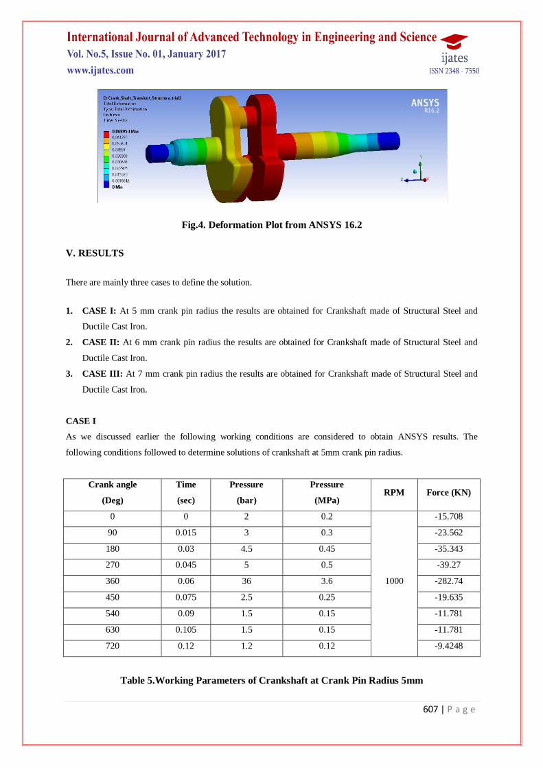
4.6 Sample Results
In the previous step we can apply the boundary conditions in latest version of ANSYS 16.2. We can import the
crankshaft 3D model from the HYPERMESH 13. software. After applying the boundary conditions we can
solve the crankshaft model using the ANSYS software. The following Fig 4. shows a sample.
607 | P a g e
Fig.4. Deformation Plot from ANSYS 16.2
V. RESULTS
There are mainly three cases to define the solution.
1. CASE I: At 5 mm crank pin radius the results are obtained for Crankshaft made of Structural Steel and
Ductile Cast Iron.
2. CASE II: At 6 mm crank pin radius the results are obtained for Crankshaft made of Structural Steel and
Ductile Cast Iron.
3. CASE III: At 7 mm crank pin radius the results are obtained for Crankshaft made of Structural Steel and
Ductile Cast Iron.
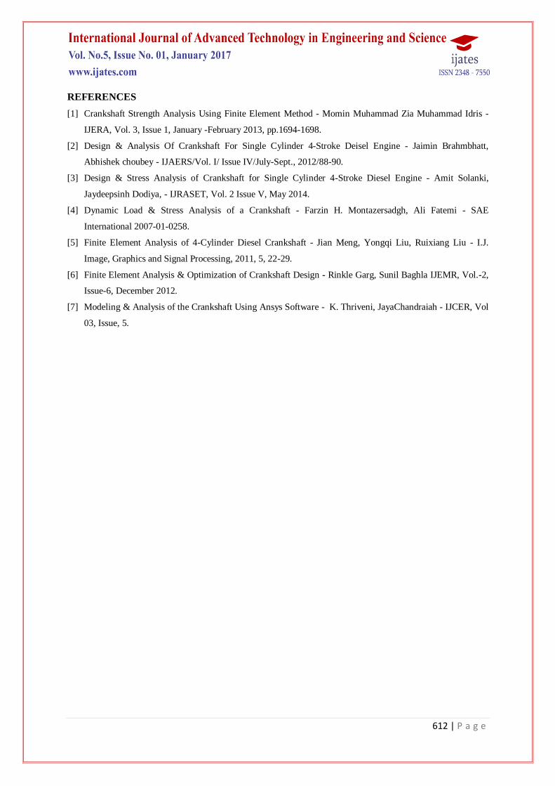
CASE I
As we discussed earlier the following working conditions are considered to obtain ANSYS results. The
following conditions followed to determine solutions of crankshaft at 5mm crank pin radius.
Crank angle
(Deg)
Time
(sec)
Pressure
(bar)
Pressure
(MPa) RPM Force (KN)
0 0 2 0.2
1000
-15.708
90 0.015 3 0.3 -23.562
180 0.03 4.5 0.45 -35.343
270 0.045 5 0.5 -39.27
360 0.06 36 3.6 -282.74
450 0.075 2.5 0.25 -19.635
540 0.09 1.5 0.15 -11.781
630 0.105 1.5 0.15 -11.781
720 0.12 1.2 0.12 -9.4248
Table 5.Working Parameters of Crankshaft at Crank Pin Radius 5mm

608 | P a g e
A. Structural Steel
1. Total Deformation Plot.
Fig.5.Total Deformation Plot
The Maximum deformation observed is 0.023657 mm at 0.06 s or at 360 deg crank angle (at 36 bar pressure).
2. Von Mises Stress Plot
Fig. 6.Von Mises Stress
The Maximum Von-Mises stress observed is 73.898 MPa at 0.06 s or at 360 deg crank angle (at 36 bar
pressure).
3. 1st Principal Stress Plot (Tension)
Fig.7.1st Principal Stress Plot
The Maximum 1st Principal stress observed is 77.06 MPa (tension) at 0.06 s or at 360 deg crank angle (at 36 bar
pressure).

609 | P a g e
4. 3rd
Principal Stress Plot (Compression)
Fig.8. 3rd
Principal Stress Plot
The Maximum 3rd Principal stress observed is 98.948 MPa (compression) at 0.06 s or at 360 deg crank angle (at
36 bar pressure).
B. Ductile Cast Iron
1. Total Deformation Plot
Fig.9.Total Deformation
The Maximum deformation observed is 0.026273 mm at 0.06 s or at 360 deg crank angle (at 36 bar pressure).
2. Von Mises Stress Plot
Fig.10. Von Mises Stress

610 | P a g e
The Maximum Von-Mises stress observed is 73.861 MPa at 0.06 s or at 360 deg crank angle (at 36 bar
pressure).
3. 1st Principal Stress Plot
Figure11. 1st Principal Stress
The Maximum 1st Principal stress observed is 77.021 MPa (tension) at 0.06 s or at 360 deg crank angle (at 36
bar pressure).
4. 3rd
Principal Stress Plot
Figure 6.8 3rd Principal Stress
The Maximum 3rd Principal stress observed is 98.898 MPa (compression) at 0.06 s or at 360 deg crank angle (at
36 bar pressure).
VI. RESULTS SUMMARY
Similarly, by solving Case II and Case III the following results were obtained. The following table shows the
results summary of the Case I, Case II and Case III. This summary will clarify the different result comparisons
of different parameters such as deformation, Von – Mises Stress, 1st Principal Stress and 3rd Principal Stress.

611 | P a g e
These results are obtained for different materials such as Structural steel (SS) and Ductile Cast Iron (Ductile CI)
with respect to the different crank pin radius. (5mm, 6mm and 7mm).
Table6. Results Summary
VII. CONCLUSION
1. The results of displacements, stresses will be presented and the conclusions about the impact of the material
change and impact of the crank pin radius on the fatigue strength of the crank shaft will be presented.
2. From the Preliminary transient structural analysis performed on the crank shaft it is observed that the given
crank shaft is close to the yielding and requires some design changes to have sufficient FOS (considering
the Yield stress of steel as 240 MPa). Finally I would like to conclude that at 5mm, 6mm, and 7mm crank
pin radius will gives satisfactory results while choosing the structural steel as crankshaft material while
considering stress by maintaining enough structural strength and stability.
3. But at 5 mm crank pin radius I got 2.356% reduction in weight while comparing other cases. This reduction
is very important in case of mass production. Also the deformation or displacement at 5mm crank radius, I
got 51.711% reduction while compare with other cases. So for structural steel at 5 mm radius I got more
satisfied results comparing with other cases.
4. The stress and displacements were extracted from the ANSYS Transient Structural analysis simulation as
reported. The above results were calculated for at least 2 different crankshaft materials and comparison had
made.
5. I was concluded that the failure of crank shaft is reduced by changing the radius of crank pin by altering
different materials.
6. Also the structural integrity of the crankshaft will be evaluated by applying pressure using the P-theta
diagram.
7. The 3D CAD model will be created by using commercial modeling software CATIA v5 and the numerical
models will be prepared using HYPERMESHv11. These models will be solved using ANSYS v16.2.
Result--> Displacement
(mm)
Von-Mises Stress
(MPa)
1st Principal Stress
(MPa)
3rd Principal Stress
(MPa)
Material-
-> SS Ductile CI SS Ductile CI SS Ductile CI SS Ductile CI
5mm 0.023657 0.02673 73.898 73.861 77.06 77.021 98.948 98.898
6mm 0.033804 0.037553 108.32 108.29 108.1 108.1 145.42 145.38
7mm 0.045748 0.050831 135.36 135.34 150.4 150.4 184.79 184.76
612 | P a g e
REFERENCES
[1] Crankshaft Strength Analysis Using Finite Element Method - Momin Muhammad Zia Muhammad Idris -
IJERA, Vol. 3, Issue 1, January -February 2013, pp.1694-1698.
[2] Design & Analysis Of Crankshaft For Single Cylinder 4-Stroke Deisel Engine - Jaimin Brahmbhatt,
Abhishek choubey - IJAERS/Vol. I/ Issue IV/July-Sept., 2012/88-90.
[3] Design & Stress Analysis of Crankshaft for Single Cylinder 4-Stroke Diesel Engine - Amit Solanki,
Jaydeepsinh Dodiya, - IJRASET, Vol. 2 Issue V, May 2014.
[4] Dynamic Load & Stress Analysis of a Crankshaft - Farzin H. Montazersadgh, Ali Fatemi - SAE
International 2007-01-0258.
[5] Finite Element Analysis of 4-Cylinder Diesel Crankshaft - Jian Meng, Yongqi Liu, Ruixiang Liu - I.J.
Image, Graphics and Signal Processing, 2011, 5, 22-29.
[6] Finite Element Analysis & Optimization of Crankshaft Design - Rinkle Garg, Sunil Baghla IJEMR, Vol.-2,
Issue-6, December 2012.
[7] Modeling & Analysis of the Crankshaft Using Ansys Software - K. Thriveni, JayaChandraiah - IJCER, Vol
03, Issue, 5.