Embed Size (px)
Citation preview

Transient Electromagnetic-Thermal FE-Model of a SPICE-Coupled Transformer Including Eddy Currents
Holger Neubert*,1, Thomas Bödrich1 and Rolf Disselnkötter2
1 Technische Universität Dresden, Institute of Electromechanical and Electronic Design, Germany, 2 ABB AG, Corporate Research Center Germany, Ladenburg, Germany
* Corresponding author: D-01069 Dresden, Germany, [email protected]
Faculty of Electrical and Computer Engineering Institute of Electromechanical and Electronic Design

H. Neubert, T. Bödrich, R. Disselnkötter: Electromagnetic-Thermal Model of a TransformerCOMSOL Conference Stuttgart 2011, October 26 – 28
2/24
Outline
1. Introduction2. Modelling Approach3. Electromagnetic FE Model4. Thermal Model5. Coupled Time-dependent Simulation6. Summary
H. Neubert, T. Bödrich, R. Disselnkötter: Electromagnetic-Thermal Model of a TransformerCOMSOL Conference Stuttgart 2011, October 26 – 28
3/24
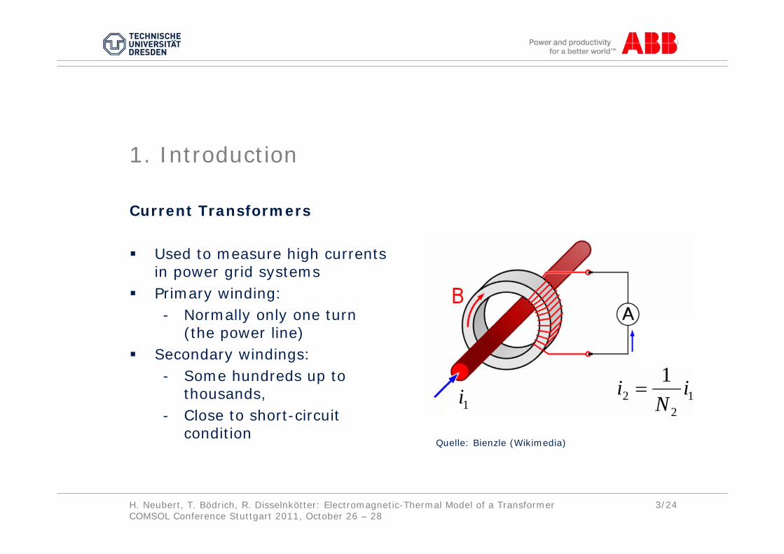
Current Transformers
Used to measure high currents in power grid systemsPrimary winding:- Normally only one turn
(the power line)Secondary windings:- Some hundreds up to
thousands, - Close to short-circuit
condition
1. Introduction
Quelle: Bienzle (Wikimedia)
1i 12
21 i
Ni =

H. Neubert, T. Bödrich, R. Disselnkötter: Electromagnetic-Thermal Model of a TransformerCOMSOL Conference Stuttgart 2011, October 26 – 28
4/24
Bar-typeCurrent Transformer(Low Voltage)
Quelle: ABB Stotz S&J Quelle: ABB
Pole mountedCurrent Transformer(High Voltage)

H. Neubert, T. Bödrich, R. Disselnkötter: Electromagnetic-Thermal Model of a TransformerCOMSOL Conference Stuttgart 2011, October 26 – 28
5/24
2. Modelling Approach
Coupled ModelElectromagnetic FE model of the transformer Network models of the primary and secondary circuitry Thermal FE model of the transformer

H. Neubert, T. Bödrich, R. Disselnkötter: Electromagnetic-Thermal Model of a TransformerCOMSOL Conference Stuttgart 2011, October 26 – 28
6/24
( )rq( )rT
Electromagnetic FE model
Thermal FE model
H. Neubert, T. Bödrich, R. Disselnkötter: Electromagnetic-Thermal Model of a TransformerCOMSOL Conference Stuttgart 2011, October 26 – 28
7/24
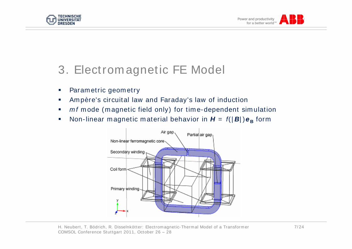
3. Electromagnetic FE Model
Parametric geometryAmpère's circuital law and Faraday's law of inductionmf mode (magnetic field only) for time-dependent simulationNon-linear magnetic material behavior in H = f(|B|)eB form

H. Neubert, T. Bödrich, R. Disselnkötter: Electromagnetic-Thermal Model of a TransformerCOMSOL Conference Stuttgart 2011, October 26 – 28
8/24
Modelling of Eddy Currents
Power Line (Primary winding):- Sinusoidal primary current i1(t) is modeled as a total current
density Jz(r,t) inside of the bus bar- Jz(r,t) can not be imposed directly as an external current
density
- A global equation (ge mode) determines Jez inside of the bus bar by
- Jz(r,t) in the primary conductor is calculated from
( ) ( ) ( )tJtJtJ ,,, izezz rrr +=
0prim1 =− Ii
( )∫=prim
zprim
prim1
V
dVJL
I

H. Neubert, T. Bödrich, R. Disselnkötter: Electromagnetic-Thermal Model of a TransformerCOMSOL Conference Stuttgart 2011, October 26 – 28
9/24
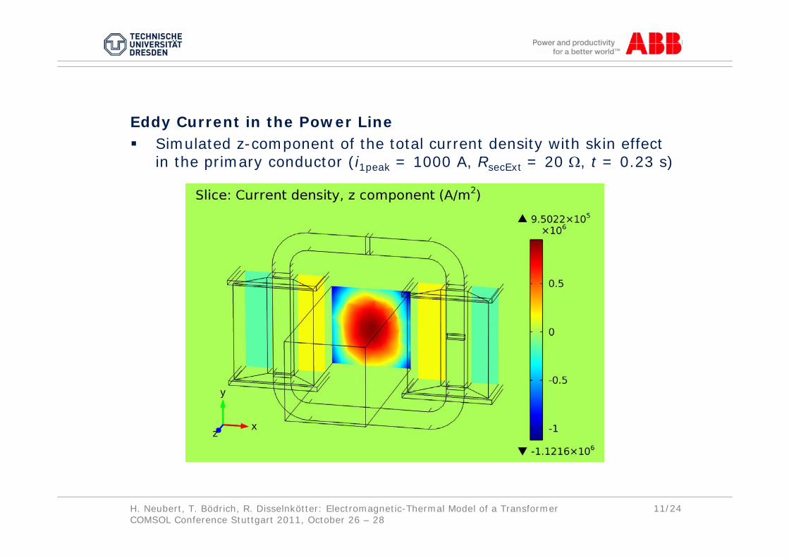
Eddy Current in the Power LineSimulated z-component of the total current density with skin effect in the primary conductor (i1peak = 1000 A, RsecExt = 20 Ω, t = 0.23 s)

H. Neubert, T. Bödrich, R. Disselnkötter: Electromagnetic-Thermal Model of a TransformerCOMSOL Conference Stuttgart 2011, October 26 – 28
10/24
Modelling of Eddy Currents
Secondary windings:- Modeled as bulk material (eight prismatic bodies)- Conductivity is set to 10 S/m to supress eddy current effects- Secondary current i2(t) is modeled as an external current
density, derived from the induced voltage
H. Neubert, T. Bödrich, R. Disselnkötter: Electromagnetic-Thermal Model of a TransformerCOMSOL Conference Stuttgart 2011, October 26 – 28
11/24
Eddy Current in the Power LineSimulated z-component of the total current density with skin effect in the primary conductor (i1peak = 1000 A, RsecExt = 20 Ω, t = 0.23 s)

H. Neubert, T. Bödrich, R. Disselnkötter: Electromagnetic-Thermal Model of a TransformerCOMSOL Conference Stuttgart 2011, October 26 – 28
12/24
Non-linear Magnetic Behavior
H = f(|B|)eB form avoids circular variable definitions in constitutiverelationsSeveral approximation approaches with remarkable influence on solution time
no convergenceNearest neighbour
≈ 100Cubic spline interpolation
4.0Linear interpolation
1.3Global rational function
1.0Piecewise cubic interpolation
Relative solution timeApproximation approach
H. Neubert, T. Bödrich, R. Disselnkötter: Electromagnetic-Thermal Model of a TransformerCOMSOL Conference Stuttgart 2011, October 26 – 28
13/24
Non-linear Magnetic Behavior
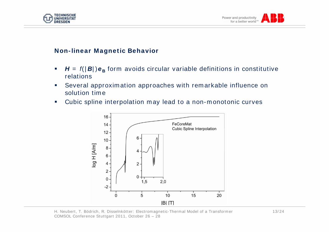
H = f(|B|)eB form avoids circular variable definitions in constitutiverelationsSeveral approximation approaches with remarkable influence on solution time Cubic spline interpolation may lead to a non-monotonic curves

H. Neubert, T. Bödrich, R. Disselnkötter: Electromagnetic-Thermal Model of a TransformerCOMSOL Conference Stuttgart 2011, October 26 – 28
14/24
Coupling with SPICE Components
cir mode Sinusoidal current source at the primary side External load resistor at the secondary side coupled to the secondary windings (External I vs. U element)Variable
i2coilsec ViRV −=sec
8212i
)(A
VVVNV
+++=
K

H. Neubert, T. Bödrich, R. Disselnkötter: Electromagnetic-Thermal Model of a TransformerCOMSOL Conference Stuttgart 2011, October 26 – 28
15/24
4. Thermal Model
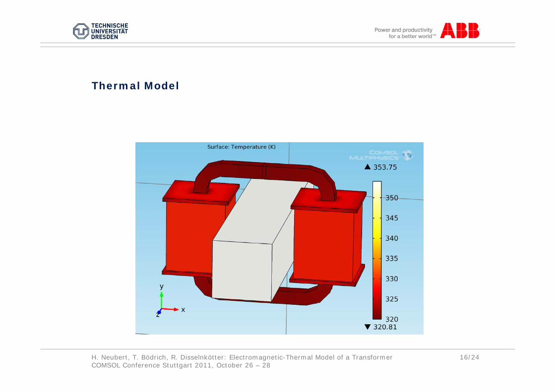
Temperature-dependent electrical conductivity of the conductorsHeat conduction in solids applying the ht mode- Heat sources (mean value over a period of the losses field)- Heat conduction in solids and narrow air gaps,- Thermal contact resistances between solids which are in
mechanical contact- External convection on solid-air interfaces applying empirical
correlationsTime-average of the local power loss density in the time interval [0, ti]
( ) ( )[ ] τστ
dJ
ttq
t
i∫=i
0
2
i,1
,r
r
H. Neubert, T. Bödrich, R. Disselnkötter: Electromagnetic-Thermal Model of a TransformerCOMSOL Conference Stuttgart 2011, October 26 – 28
16/24
Thermal Model
H. Neubert, T. Bödrich, R. Disselnkötter: Electromagnetic-Thermal Model of a TransformerCOMSOL Conference Stuttgart 2011, October 26 – 28
17/24
5. Coupled Time-dependent Simulation
Time-dependent simulationTime scales of the electromagnetic and the thermal model are very different Bi-directionally coupling of the electromagnetic and the thermal modelIterating alternate solutions: - Stationary study steps of the thermal model - Time-dependent study steps of the electromagnetic and circuit
model

H. Neubert, T. Bödrich, R. Disselnkötter: Electromagnetic-Thermal Model of a TransformerCOMSOL Conference Stuttgart 2011, October 26 – 28
18/24
Convergence
H. Neubert, T. Bödrich, R. Disselnkötter: Electromagnetic-Thermal Model of a TransformerCOMSOL Conference Stuttgart 2011, October 26 – 28
19/24
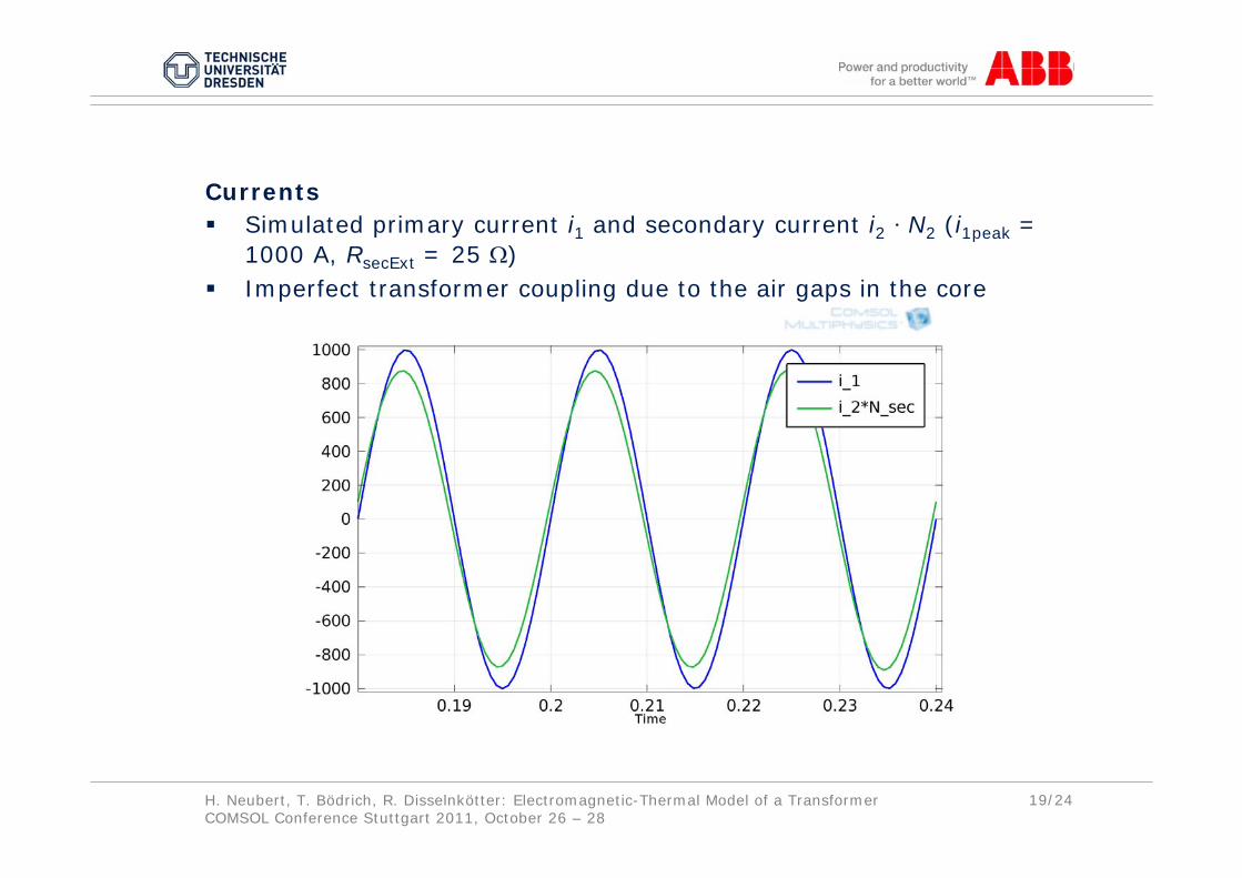
CurrentsSimulated primary current i1 and secondary current i2 ⋅ N2 (i1peak = 1000 A, RsecExt = 25 Ω)Imperfect transformer coupling due to the air gaps in the core
H. Neubert, T. Bödrich, R. Disselnkötter: Electromagnetic-Thermal Model of a TransformerCOMSOL Conference Stuttgart 2011, October 26 – 28
20/24
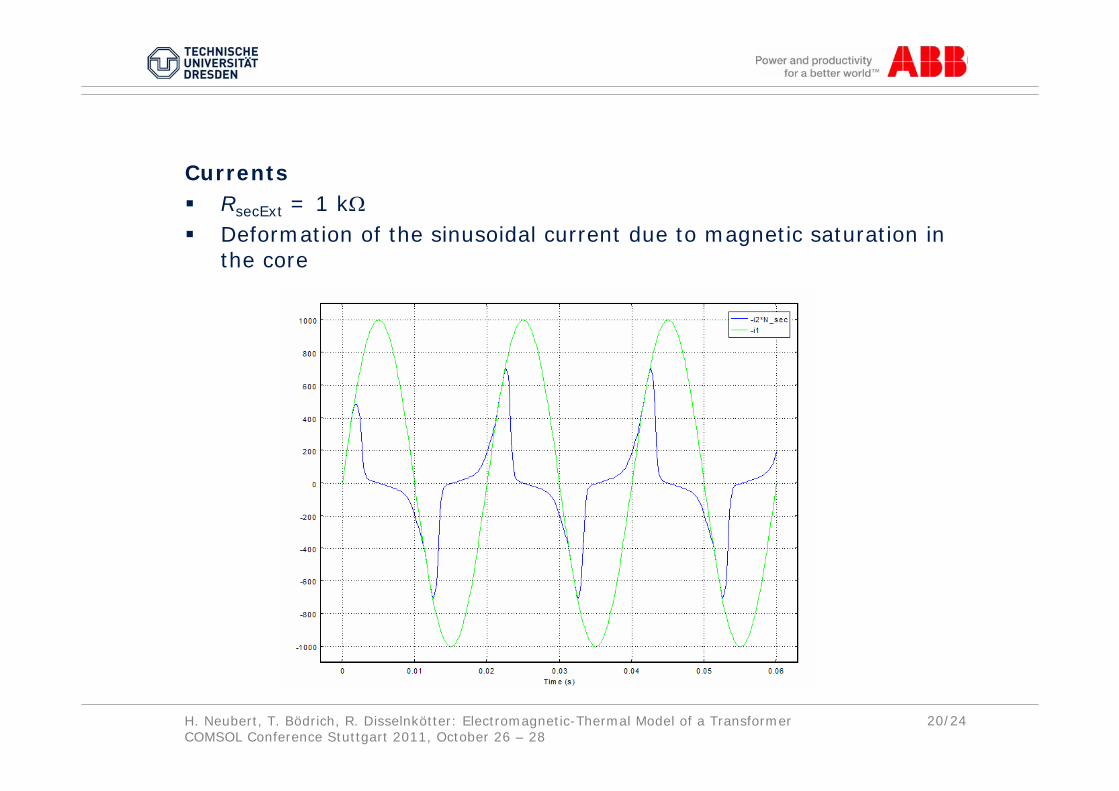
CurrentsRsecExt = 1 kΩDeformation of the sinusoidal current due to magnetic saturation in the core

H. Neubert, T. Bödrich, R. Disselnkötter: Electromagnetic-Thermal Model of a TransformerCOMSOL Conference Stuttgart 2011, October 26 – 28
21/24
Current densityi1peak = 1000 A, RsecExt = 25 Ω

H. Neubert, T. Bödrich, R. Disselnkötter: Electromagnetic-Thermal Model of a TransformerCOMSOL Conference Stuttgart 2011, October 26 – 28
22/24
Flux densityi1peak = 1000 A, RsecExt = 25 Ω
H. Neubert, T. Bödrich, R. Disselnkötter: Electromagnetic-Thermal Model of a TransformerCOMSOL Conference Stuttgart 2011, October 26 – 28
23/24
6. Summary
Transient Electromagnetic-Thermal FE-Model of a SPICE-Coupled Transformer Including Eddy Currents
Time-dependent simulation of a transformer coupled to an externalcircuitryNon-linear magnetic material properties based on experimental dataEddy current effects are included using a global equationTime-averaged power loss density distributionThe bi-directionally coupled thermal model considers the influenceof the temperature on electrical material propertiesFuture work will focus on- consideration of the transformer core lamination, - the anisotropic material behaviour inside of the coils
H. Neubert, T. Bödrich, R. Disselnkötter: Electromagnetic-Thermal Model of a TransformerCOMSOL Conference Stuttgart 2011, October 26 – 28
24/24
Thank you very muchfor your attention.