Embed Size (px)
Citation preview
© 2016 Transceiver – QSG 1.0 1 / 14
Transceiver
Quick Start Guide
What is in the box ................................................................................................. 3
What does it do ..................................................................................................... 5
How to build a setup ............................................................................................ 6
Verification of the setup ..................................................................................... 10
Help and troubleshooting .................................................................................. 11
Technical specifications .................................................................................... 12
Declaration of conformity .................................................................................. 14
© 2016 Transceiver – QSG 1.0 2 / 14
Disclaimer
Every effort has been made to make this document as a complete and as
accurate as possible, but no warranty of fitness is implied. The information is
provided on an as-is basis. Riscure shall have neither liability nor responsibility to
any person or entity with respect to any loss or damage arising from the
information contained in this document.
The information contained in this document is subject to change without notice.
This tool must be used according to the user guide. Any operation related to
maintenance, repair or calibration must be carried out by qualified personnel.
Consequently, in case of failure, contact Riscure about the procedure to follow.
Copyright
Copyright (c) 2015-2016 Riscure BV. All rights reserved. No part of this document
may be reproduced nor translated by any means without the written consent of
Riscure.
Manufactured by
Riscure BV
Delftechpark 49, 2628 XJ Delft, The Netherlands
Phone: +31 15 251 40 90, Fax: +31 15 251 40 99
Email: [email protected]
Web: www.riscure.com
© 2016 Transceiver – QSG 1.0 3 / 14
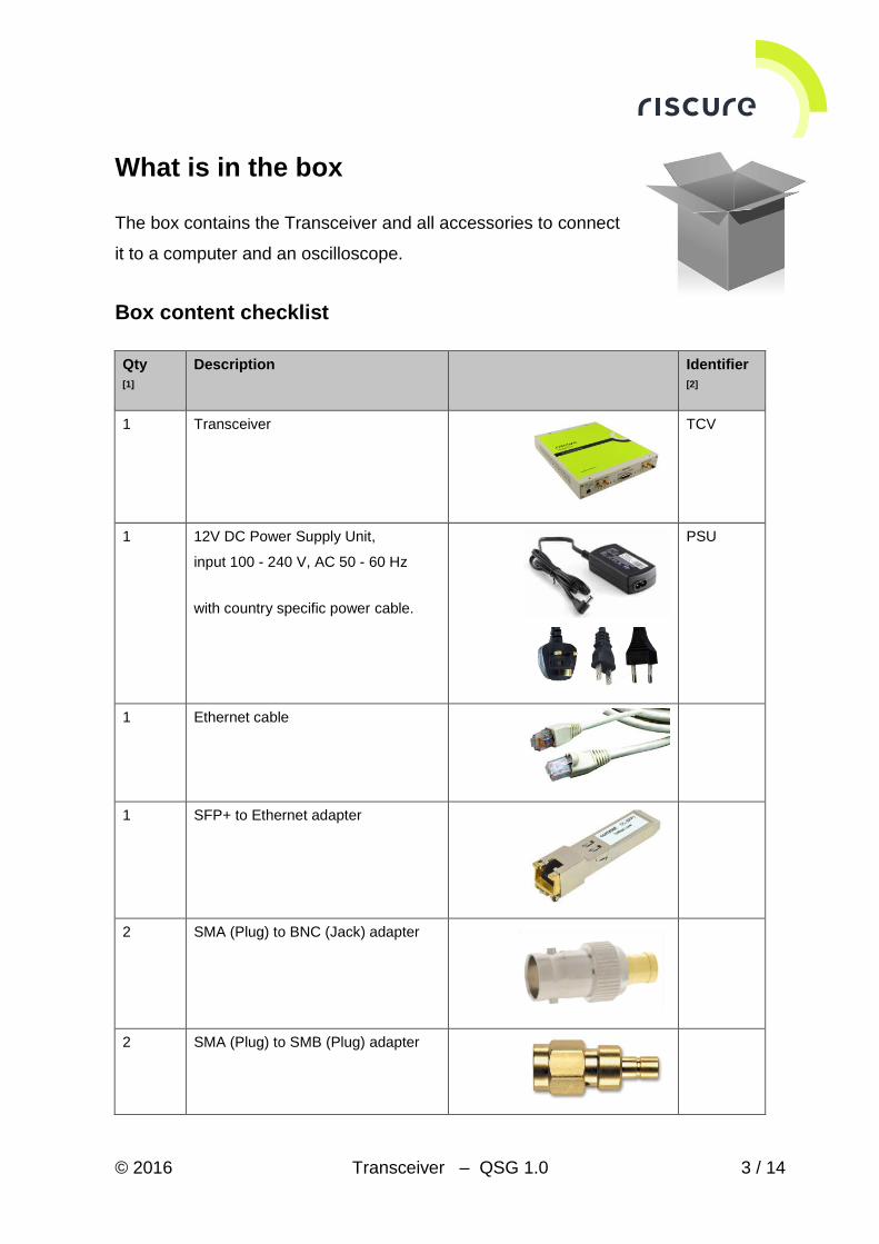
What is in the box
The box contains the Transceiver and all accessories to connect
it to a computer and an oscilloscope.
Box content checklist
Qty
[1]
Description Identifier
[2]
1 Transceiver
TCV
1 12V DC Power Supply Unit,
input 100 - 240 V, AC 50 - 60 Hz
with country specific power cable.
PSU
1 Ethernet cable
1 SFP+ to Ethernet adapter
2 SMA (Plug) to BNC (Jack) adapter
2 SMA (Plug) to SMB (Plug) adapter
© 2016 Transceiver – QSG 1.0 4 / 14
Qty
[1]
Description Identifier
[2]
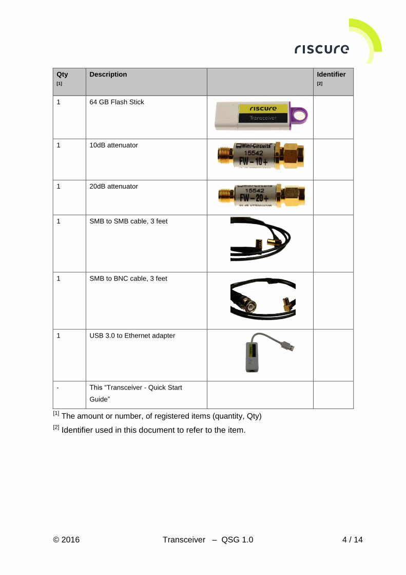
1 64 GB Flash Stick
1 10dB attenuator
1 20dB attenuator
1 SMB to SMB cable, 3 feet
1 SMB to BNC cable, 3 feet
1 USB 3.0 to Ethernet adapter
- This “Transceiver - Quick Start
Guide”
[1] The amount or number, of registered items (quantity, Qty)
[2] Identifier used in this document to refer to the item.
© 2016 Transceiver – QSG 1.0 5 / 14
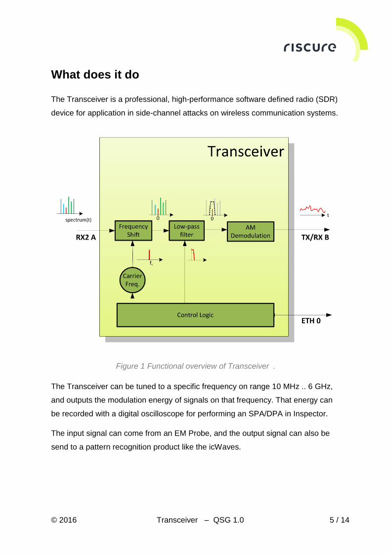
What does it do
The Transceiver is a professional, high-performance software defined radio (SDR)
device for application in side-channel attacks on wireless communication systems.
Figure 1 Functional overview of Transceiver .
The Transceiver can be tuned to a specific frequency on range 10 MHz .. 6 GHz,
and outputs the modulation energy of signals on that frequency. That energy can
be recorded with a digital oscilloscope for performing an SPA/DPA in Inspector.
The input signal can come from an EM Probe, and the output signal can also be
send to a pattern recognition product like the icWaves.
© 2016 Transceiver – QSG 1.0 6 / 14
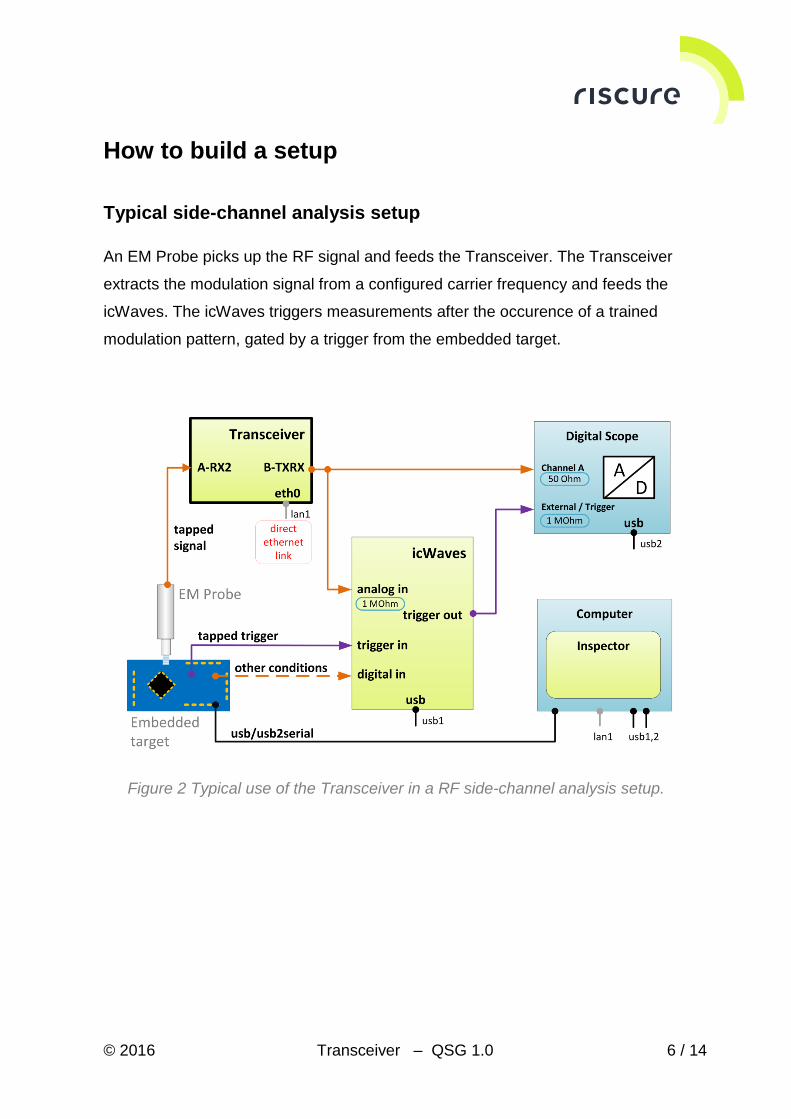
How to build a setup
Typical side-channel analysis setup
An EM Probe picks up the RF signal and feeds the Transceiver. The Transceiver
extracts the modulation signal from a configured carrier frequency and feeds the
icWaves. The icWaves triggers measurements after the occurence of a trained
modulation pattern, gated by a trigger from the embedded target.
Figure 2 Typical use of the Transceiver in a RF side-channel analysis setup.
© 2016 Transceiver – QSG 1.0 7 / 14
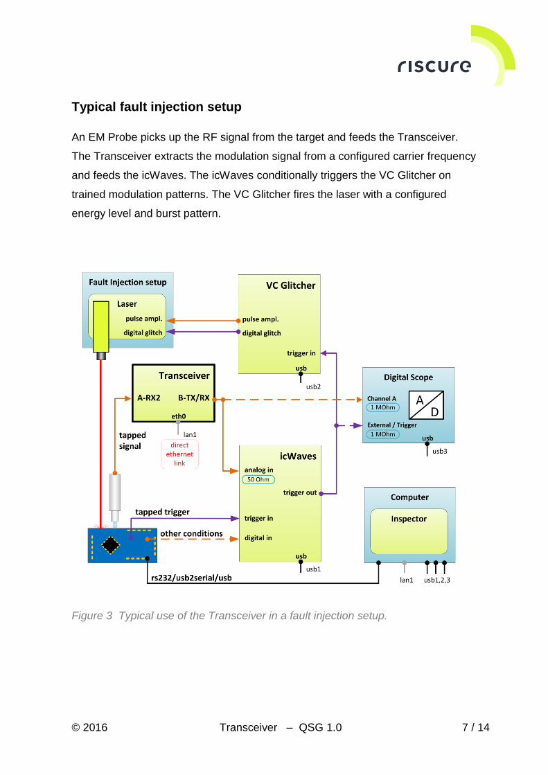
Typical fault injection setup
An EM Probe picks up the RF signal from the target and feeds the Transceiver.
The Transceiver extracts the modulation signal from a configured carrier frequency
and feeds the icWaves. The icWaves conditionally triggers the VC Glitcher on
trained modulation patterns. The VC Glitcher fires the laser with a configured
energy level and burst pattern.
Figure 3 Typical use of the Transceiver in a fault injection setup.
© 2016 Transceiver – QSG 1.0 8 / 14
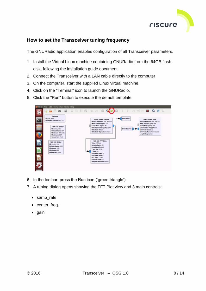
How to set the Transceiver tuning frequency
The GNURadio application enables configuration of all Transceiver parameters.
1. Install the Virtual Linux machine containing GNURadio from the 64GB flash
disk, following the installation guide document.
2. Connect the Transceiver with a LAN cable directly to the computer
3. On the computer, start the supplied Linux virtual machine.
4. Click on the "Teminal" icon to launch the GNURadio.
5. Click the "Run" button to execute the default template.
6. In the toolbar, press the Run icon (‘green triangle’)
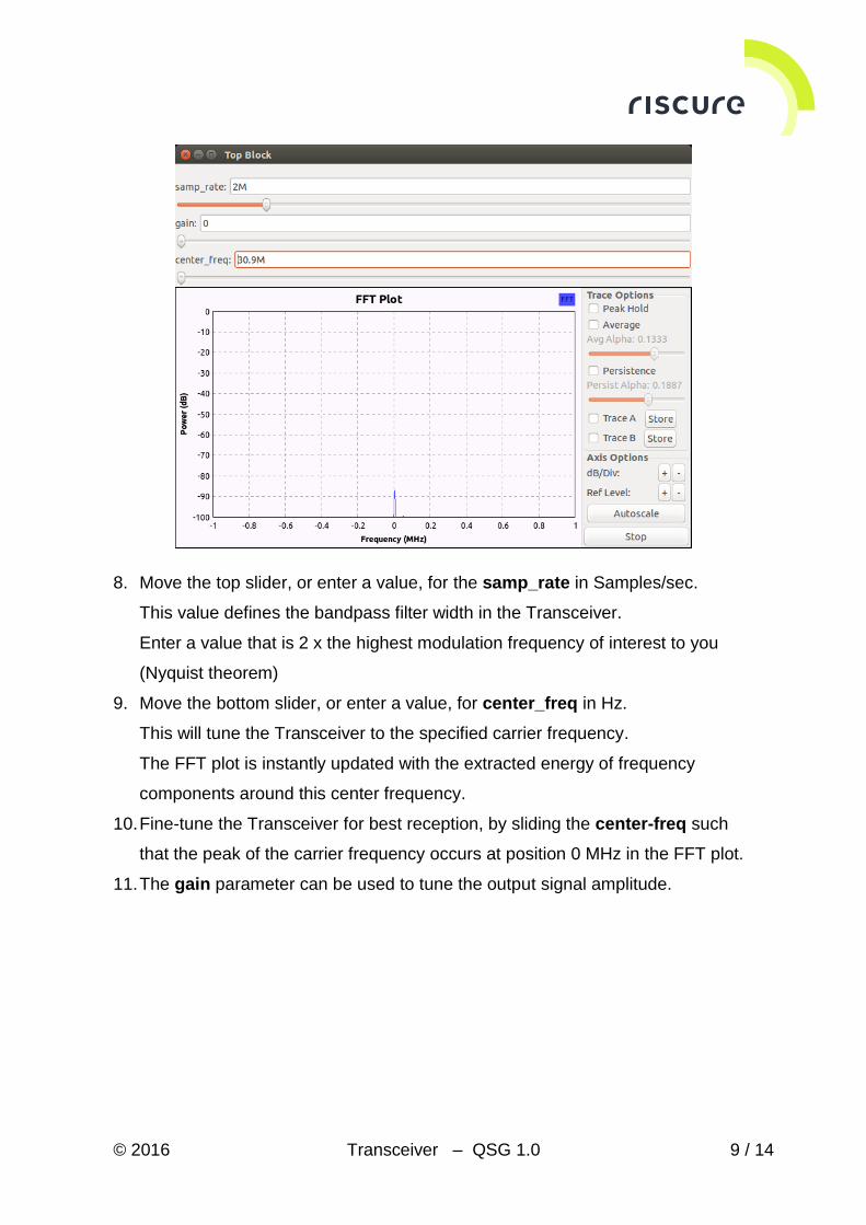
7. A tuning dialog opens showing the FFT Plot view and 3 main controls:
samp_rate
center_freq.
gain
© 2016 Transceiver – QSG 1.0 9 / 14
8. Move the top slider, or enter a value, for the samp_rate in Samples/sec.
This value defines the bandpass filter width in the Transceiver.
Enter a value that is 2 x the highest modulation frequency of interest to you
(Nyquist theorem)
9. Move the bottom slider, or enter a value, for center_freq in Hz.
This will tune the Transceiver to the specified carrier frequency.
The FFT plot is instantly updated with the extracted energy of frequency
components around this center frequency.
10. Fine-tune the Transceiver for best reception, by sliding the center-freq such
that the peak of the carrier frequency occurs at position 0 MHz in the FFT plot.
11. The gain parameter can be used to tune the output signal amplitude.
© 2016 Transceiver – QSG 1.0 10 / 14
Verification of the setup
Follow the next checks to verify a correct setup:
1. Is the Transceiver powered?
2. Is the Transceiver recognized?
3. Is the Transceiver responding to commands?
Please ensure that a check is successful, before going to the next one. If a check
is not successful, refer to page 11 for solutions.
Check 1 - Is the Transceiver powered?
The Transceiver is powered when the LED in the PWR button is ON.
Check 2 - Is the Transceiver recognized?
1. Connect the Transceiver with a LAN cable directly to a computer.
2. Switch the Transceiver ON.
3. Set the host machine IP to 192.168.10.1, with subnet mask of 255.255.255.0
4. Open any terminal.
5. Type: ping 192.168.10.2
The Transceiver is reachable and recognized when ping reports low response time
values (typically < 5 ms).
Check 3- Is the Transceiver responding to commands?
Preparation: Start the Linux virtual machine with the GnuRadio application.
1. Use the shortcut on the desktop to start GNURadio.
2. On the toolbar, press Run-icon.
3. Set samp_rate to 2M
4. Move the center_freq slider
If a clear peak can be found in the FFT Plot, then the Transceiver is working.
© 2016 Transceiver – QSG 1.0 11 / 14
Help and troubleshooting
Common problems
The Output
Signal is too weak
Configure the gain parameter with a higher value.
Still have questions?
Visit the Riscure Support Portal: https://support.riscure.com

© 2016 Transceiver – QSG 1.0 12 / 14
Technical specifications
The Transceiver is a software customized version of the high-end Ettus Research
USRP X310 product. For hardware specifications, refer to Ettus X300/X310
Specification Sheet.
The Transceiver is configured with the GNURadio application, provided as a
ready-to-run Linux virtual machine.
Operational conditions
Room temperature 20 – 30 °C, (68 – 86 °F).
Do not block the ventilation holes. A blocked air flow may cause
malfunction or break down.
Maintain stable environmental conditions (temperature, humidity, airflow
etc.) in order to reliably repeat tests and compare test results.
Power supply input
12 V DC, max 45 W.
Networking
RJ45, LAN
Fixed static IP-address, 192.168.10.2
For direct connection to client computer.
Tuning characteristics
Carrier frequency, software adjustable, 10 MHz .. 6000 MHz
Filter bandwidth, software adjustable, 0.4 MHz .. 160 MHz
© 2016 Transceiver – QSG 1.0 13 / 14
Product case
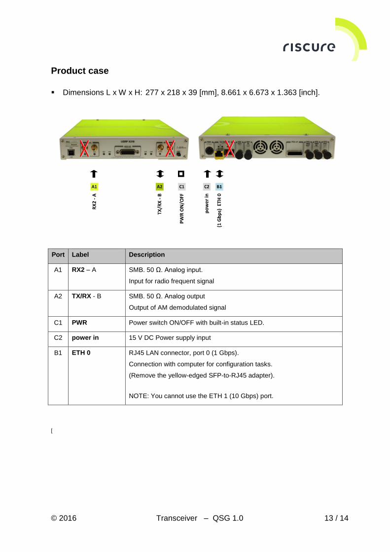
Dimensions L x W x H: 277 x 218 x 39 [mm], 8.661 x 6.673 x 1.363 [inch].
Port Label Description
A1 RX2 – A SMB. 50 Ω. Analog input.
Input for radio frequent signal
A2 TX/RX - B SMB. 50 Ω. Analog output
Output of AM demodulated signal
C1 PWR Power switch ON/OFF with built-in status LED.
C2 power in 15 V DC Power supply input
B1 ETH 0 RJ45 LAN connector, port 0 (1 Gbps).
Connection with computer for configuration tasks.
(Remove the yellow-edged SFP-to-RJ45 adapter).
NOTE: You cannot use the ETH 1 (10 Gbps) port.
[
© 2016 Transceiver – QSG 1.0 14 / 14
Declaration of conformity