Embed Size (px)
Citation preview

electric chain hoiststralift® TE
Operation & Maintenance Manualfor Electric Powered Chain Hoists
For 1/8 to 2 toncapacity hoists:
TE 125
TE 250
TE 500
TE 1000
TE 2000meets or exceedsANSI/ASME B 30.16equipment in accordance with CE directivesOVERHEAD HOISTS
Version: 2005
Date:____________________Issued By:________________Serial Number:_____________

2
Our tralift TE electric chain hoist is built in accordance with the specifications contained inthis operating, maintenance, and parts manual and complies with:
• Applicable sections of the "ANSI/ASME B30.16 "Overhead hoists" and ASME HST-IM standard.
• The National Electrical Code (ANSI/NFPA 70)• The Occupational Safety and Health Act (OSHA) 29 CFR1910, 1926
ADDITIONAL RELATED STANDARDS
The latest revision approved by the American National Standards Institute applies:
• ANSI Z244.1 Safety Requirements for the lockout/ tag out of energy sources• ANSI/ASME B30.9 Slings• ANSI/ASME B30.20 Below-the-Hook lifting devices• ANSI/ASME B30.10 Hooks• ANSI Z241.2 Safety Requirements for Melting and Pouring of Metals in the
Metalcasting Industry• References for CSA codes Canadian Electrical Standards• CE Certified
As stated by OSHA, the National Electrical Code shall apply to electric chain hoists so endusers or their installers are required to provide current overload protection and groundingon the circuit section. To comply with the application sections of these articles, all theinstallations have to be checked.
Symbol Code Word Definition Possible consequence ofnon-compliance
WARNING IMMEDIATE or possible imminentdanger Fatal or serious injury!
CAUTION Possible danger situation Minor injuries to persons!
NOTE Possible danger situation Damage to equipment orit's surroundings
N/A Instruction for documentation inwriting (i.e record keeping) N/A
Explanation of Symbols used in this manual
Table 001

GENERAL WARNING
READ THIS GENERAL WARNING FIRST
IN HOISTING OPERATIONS, SAFETY AND PROPER OPERATION IS A MATTER OF LIFE ORDEATH FOR RIGGERS, OPERATORS AND BY-STANDARDS.
THIS WARNING IS YOUR SHARE OF DUTIES FOR ACHIEVING SAFETY.
YOUR DUTY TO UNDERSTAND AND COMPLY
1) It is the rigger’s, operator’s and their employer’s responsibility(if they operate under an employer’s control) to strictly conform to the following warnings.
2) It is imperative for safety and efficiency of the operations that this manual be read and FULLYUNDERSTOOD by the rigger and the operator before rigging or operating the tralift TE. ALLINSTRUCTIONS contained herein must be carefully and strictly FOLLOWED, including applicable guidelines for safe practice.
3) Should you hand over a tralift TE, under whatever conditions, to any party operating out of your control, you must join a clean copy of this manual and draw the other party’s attention that strictly following all the instructions therein is a matter of life or death.
4) Before rigging and operating this tralift TE hoist, the rigger and the operator must become aware of all the requirements of federal, state, provincial and local safety regulations not only applicable to the tralift TE hoist but also to the entire suspended system and any component ofit.
5) Tralift TE may be used in the design and manufacture of cranes or monorails. Additional equipment or devices may be required for crane and monorail to comply with applicable cranedesign and safety standards. The crane designer, crane manufacturer, or user is responsible for furnishing these additional items for compliance. Refer to ANSI/ASME B30.17, “Safety Standard For Top-Running Single Girder Cranes”, ANSI/ASME B30.2 “Safety Standard For Top-Running Double Girder Cranes”, and ANSI/ASME B30.11 “Safety Standard For UnderhungCranes and Monorails.”
6) Never use the tralift TE hoist for any job other than lifting materials according to the instructionsof this manual.
7) Never lift people or near people. Warn people of an approaching load.
8) Never use a tralift TE hoist which has been modified.
9) Never lift more than the rated load capacity of the hoist.
10) The tralift TE hoist is for lifting loads in a vertical direction. The hoist must not be used for pulling or tensioning applications.
3

4
YOUR DUTY TO INSPECT AND MAINTAIN
11) Keep this manual available at all times for easy reference whenever required. Extra copies are available from the supplier.
12) Carefully take notice of all the labels affixed to the tralift TE. Never rig or operate the hoist if anylabel(normally fixed on the hoist) is obscured or missing. The supplier will provide extra labels percustomer’s request.
13) Every time the hoist is to be rigged or used, check that the hoist, load chain and other componentsof the suspended system are complete and in good working condition prior to proceeding.
14) A careful and regular inspection of the tralift TE hoist, its load chain and other components of the installation is part of the safety requirements. If you have any questions, call the supplier.
15) Do not use a hoist with twisted, kinked, damaged or worn load chain.
16) Shut down a hoist that malfunctions or performs unusually. Report such malfunctions.
17) Do not attempt to lengthen or repair load chain.
18) Make sure hoist limit switches function properly.
YOUR DUTY TO TRAIN AND CONTROL THE OPERATOR
19) An operator must not be assigned to a hoisting job or to rigging for a job, if that person is not...a) ...mentally or physically fit for that job.b) ...trained for the job to be performed.c) ...familiar with all applicable safety rules and requirements.d) ...familiar with the scaffold equipment as rigged.e) ...trained for working under the above requirements.
20) Never disassemble the tralift TE. Except for the operations described in this manual, the maintenance, disassembly and repair of the tralift TE hoists must be performed exclusively by qualified technicians authorized in writing by the supplier. Tralift TE spare parts in accordance withthe serial number of each machine must be exclusively utilized. No substitutions are allowed.
21) Never let the tralift TE hoist and other equipment of a suspended system be managed or operated by a person other than those authorized and assigned to the job.
22) Training operators must be set up by a trained person of the user or of its technical consultant according to the working conditions. Prior to putting the equipment into operation, contact TRACTELInc.
23) Every suspended job must be placed under the control of a person having the required competence and the authority for checking that all the instructions described by this manual be regularly and efficiently carried out.

5
YOUR DUTY OF SAFETY BEYOND THE TRALIFT TE
As being only one piece of the system, the tralift TE hoist can contribute to the required SAFETY ONLY,IF …
24) ...it is fitted on compatible equipment.
25) ...other components meet the requirements of the applicable safety regulations and are of the proper quality and assembled to form a safe system.
26) ...every upper support is stable and sufficiently strong according to the load(either static or dynamic).
27) ...the supporting structure provides the requested resistance to every load to be applied(either static or dynamic) during operating the equipment.
28) ...all the requirements in strength and resistance are obtained with the necessary safety factor (see regulations and professional standards).
29) ...all the calculations, design and subsequent work necessary to the above requirements have been made by a competent person on the basis of proper technical information regarding the site.
YOUR DUTY TO AVOID TAKING RISKS
30) Do not leave a load supported by the hoist unattended unless specific precautions have been taken.
31) Should you decide that the tralift TE hoist is no longer able to be used, take precautions in disposing of it properly so that it cannot be used anymore.
32) Tralift TE hoist MUST NOT be used in explosive atmospheres. It has not been designed for such anapplication.
33) Do not operate unless the load is centered under the hoist.34) Protect the hoists load chain from weld splatter or other damaging contaminants.35) Do not operate the hoist when it is restricted from forming a straight line from hook to hook(or lug to
hook) in the direction of loading.36) Do not use the load chain as a sling.37) Do not apply the load to the tip of the hook or to the hook latch.38) Never operate a hoist unless load slings or any other approved attachments are properly sized and
seated in the hook saddle.39) Do not apply load unless load chain is properly seated in the chain wheel(s) or sprocket(s).40) Do not operate beyond the limits of the load chain travel.41) Do not allow the load chain or hook to be touched by a live welding electrode or be used as a
electrical or welding ground.42) Do not use the hoist for lifting loads that are not freely suspended or loads that are guided.43) Do not wrap the load chain around a load.
LIFTING PEOPLE OR OTHER APPLICATIONS CONTACT:
Tractel Inc., Griphoist Division
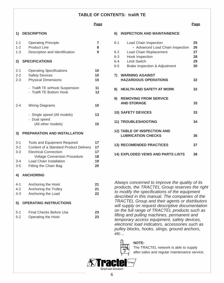
1) DESCRIPTION
1-1 Operating Principle 71-2 Product Line 81-3 Description and Identification 9
2) SPECIFICATIONS
2-1 Operating Specifications 102-2 Safety Devices 102-3 Physical Dimensions 10
- Tralift TE w/Hook Suspension 11- Tralift TE Bottom Hook 12
2-4 Wiring Diagrams 10
- Single speed (All models) 13- Dual speed
(All other models) 15
3) PREPARATION AND INSTALLATION
3-1 Tools and Equipment Required 173-2 Content of a Standard Product Delivery 173-3 Electrical Connection 17
Voltage Conversion Procedure 183-4 Load Chain Installation 193-5 Fitting the Chain Bag 20
4) ANCHORING
4-1 Anchoring the Hoist 214-2 Anchoring the Trolley 214-3 Anchoring the Load 22
5) OPERATING INSTRUCTIONS
5-1 Final Checks Before Use 235-2 Operating the Hoist 23
6) INSPECTION AND MAINTAINENCE
6-1 Load Chain Inspection 25- Advanced Load Chain Inspection 26
6-2 Load Chain Replacement 276-3 Hook Inspection 286-4 Limit Switch 296-5 Brake Inspection & Adjustment 30
7) WARNING AGAINST HAZARDOUS OPERATIONS 32
8) HEALTH AND SAFETY AT WORK 32
9) REMOVING FROM SERVICEAND STORAGE 33
10) SAFETY DEVICES 33
11) TROUBLESHOOTING 34
12) TABLE OF INSPECTION AND LUBRICATION CHECKS 36
13) RECOMENDED PRACTICES 37
14) EXPLODED VEWS AND PARTS LISTS 38
TABLE OF CONTENTS: tralift TE
Page
Always concerned to improve the quality of itsproducts, the TRACTEL Group reserves the rightto modify the specifications of the equipmentdescribed in this manual. The companies of theTRACTEL Group and their agents or distributorswill supply on request descriptive documentationon the full range of TRACTEL products such aslifting and pulling machines, permanent andtemporary access equipment, safety devices,electronic load indicators, accessories such aspulley blocks, hooks, slings, ground anchors,etc…
6
Page
NOTE:The TRACTEL network is able to supply after-sales and regular maintenance service.

7
1) DESCRIPTION
1-1 Operating Principle
The tralift TE is an electric chain hoist powered by a motor driving through a gearbox. The gearboxturns a load wheel which in turn moves the chain. One end of the chain is fitted with a load hook andthe other end is fitted with an end stop. The loose chain is stored in a chain bag.
The hoist is activated by a low voltage pendant control with three buttons: lifting, lowering andemergency stop. The hoist body includes a rigid or swivel hook to fit the hoist onto a support structure.The load is connected to the load hook directly or through an accessory such as a sling.
The hoist is equipped with an electromagnetic disc brake connected to the motor shaft. The brakeholds the suspended load when the pendant control is not activated or in case of power failure.Safety devices ensure that the hoist conforms to safety regulations.
Figure 101 displays the basic components of the tralift TE.
Figure 101
1. Hoisting motor2. Electrical controls3. Suspension hook4. Load wheel with chain guide5. Gearbox6. Load hook
7. Chain bag8. Pendant control9. Overload friction clutch10. Electromagnetic disc brake11. Paddle Limit Switches
8
76
2
1
4
9
3
510
11

8
1-2 Product Line
The tralift TE product line is composed of 7 different models outlined in Table 101. The rated loadrange of 1/8 ton to 2 ton in one or two lifting speeds is available depending on the model. On request,the hoist may be delivered with different lifting heights or pendant control cable lengths. The hoistcan be fitted with push, geared or electric drive trolley available for any model(as shown in Figure102, 103, and 104.
Model Rated Loadton (kg)
Number ofChain Falls
Load Chain Sizeφ x pitch, mm
Lifting Speedft/min. (m/min)
Lifting MotorPower
hp
Hoist Weightw/10ft (3m) of lift
lbs. (kg)
TE 125 1/8 (125) 1 4 x 12 39 (12) 39/12 (12/3.6)
0.4 0.4/0.13 55 (25)
TE 250 1/4 (250) 1 5 x 15 33 (10) 33/10 (10/3.2)
0.55 0.55/0.17 68 (31)
TE 500 1/2 (500) 2 5 x 15 16 (5) 16/5 (5/1.6)
0.55 0.55/0.17 73 (33)
TE 500 1/2 (500) 1 6.3 x 19 33 (10) 33/10 (10/3.2)
1.2 1.2/0.17 84 (38)
TE 1000 1 (1000) 2 6.3 x 19 16 (5) 16/5 (5/1.6)
1.2 1.2/0.17 95 (43)
TE 1000 1 (1000) 1 8 x 24 23 (7) 23/7 (7/2.3)
2.1 2.1/0.75 124 (56)
TE 2000 2 (2000) 2 8 x 24 13 (4) 13/3 (4/1)
2.1 2.1/0.75 141 (64)
Push Travel Trolley Geared Trolley Electric Drive TrolleyTable 101
Figure 102 Figure 103 Figure 104

1-3 Description and Identification
The tralift TE is available in one or two fallsversions(as shown in Figure 105). The tralift TE is acompact electric chain hoist consisting of:
• A rigid suspension hook or lug.
• A cast aluminum frame made of boltedmodular parts.
• A motor mounted in the hoist frame and fittedwith thermal protection.
• A lifting sub-assembly with a chain sprocketwheel, chain guide, grade 80 case hardened load chain, swiveling load hook mounted on ball bearings (with return sheave for two fallsmodels) and chain bag.
• A double gear train gearbox sub-assembly with with a friction clutch load limiting device.
• A separate asbestos-free electromagneticbrake.
• Low voltage electrical control equipment(48V).
• A set of upper and lower paddle limit switches.
• A pendant control with an emergency stopbutton.
• A phase protector.
The tralift TE range is delivered with twoidentification labels mounted on the two hoistcovers. See Figures 106 and 107.
The first label includes:
• The name of the hoist• The capacity
The second label includes:
• The specifications of the hoist.
9
CAUTION
Both hoist labels must always remain on the hoist and bereadable before using the hoist (see Figure 101 position12 page 7).
1 Fall Hoist
2 FallHoist
Figure 105
Figure 106
Figure 107
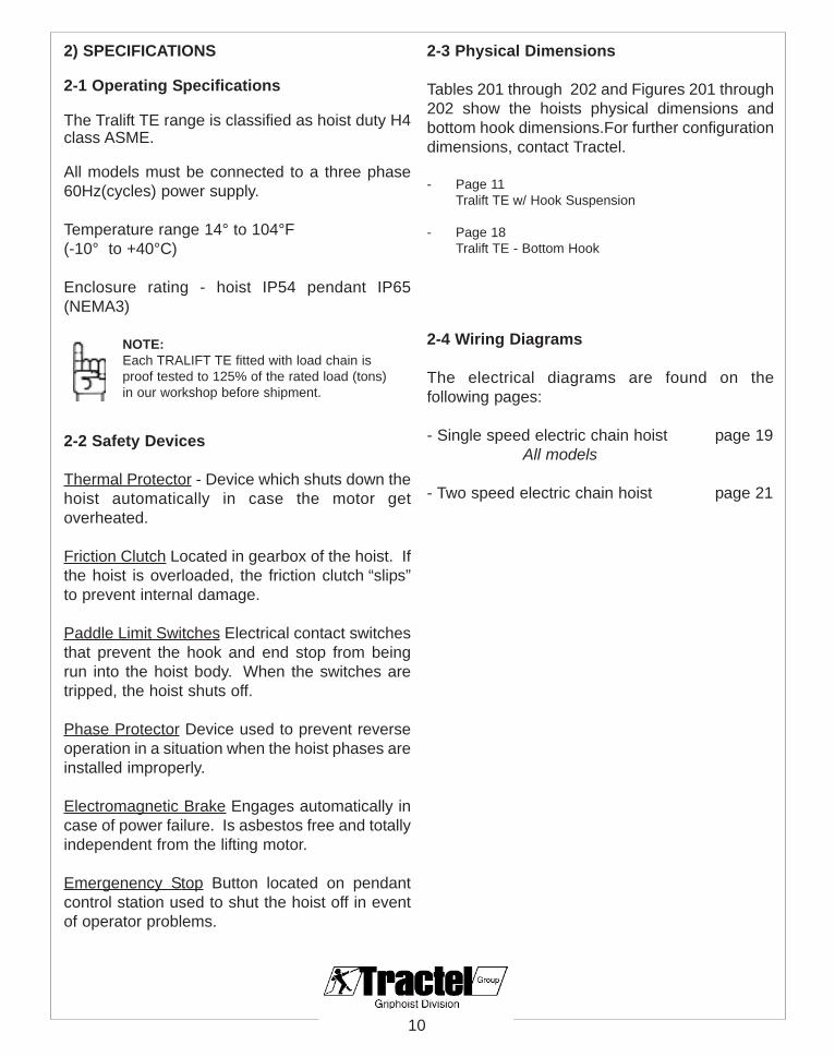
2) SPECIFICATIONS
2-1 Operating Specifications
The Tralift TE range is classified as hoist duty H4class ASME.
All models must be connected to a three phase60Hz(cycles) power supply.
Temperature range 14° to 104°F (-10° to +40°C)
Enclosure rating - hoist IP54 pendant IP65(NEMA3)
2-2 Safety Devices
Thermal Protector - Device which shuts down thehoist automatically in case the motor getoverheated.
Friction Clutch Located in gearbox of the hoist. Ifthe hoist is overloaded, the friction clutch “slips”to prevent internal damage.
Paddle Limit Switches Electrical contact switchesthat prevent the hook and end stop from beingrun into the hoist body. When the switches aretripped, the hoist shuts off.
Phase Protector Device used to prevent reverseoperation in a situation when the hoist phases areinstalled improperly.
Electromagnetic Brake Engages automatically incase of power failure. Is asbestos free and totallyindependent from the lifting motor.
Emergenency Stop Button located on pendantcontrol station used to shut the hoist off in eventof operator problems.
2-3 Physical Dimensions
Tables 201 through 202 and Figures 201 through202 show the hoists physical dimensions andbottom hook dimensions.For further configurationdimensions, contact Tractel.
- Page 11Tralift TE w/ Hook Suspension
- Page 18Tralift TE - Bottom Hook
2-4 Wiring Diagrams
The electrical diagrams are found on thefollowing pages:
- Single speed electric chain hoist page 19All models
- Two speed electric chain hoist page 21
10
NOTE:Each TRALIFT TE fitted with load chain isproof tested to 125% of the rated load (tons)in our workshop before shipment.

11
Model Number ofChain Falls L L1 E F G H J K P R
TE125 1 19.3 7.9 6.9 11.8 7.5 13 11.8 7.5 3 0.9
TE250 1 20 8.7 7.5 12.2 7.9 13.4 12.2 7.9 3 0.9
TE500 2 20 8.7 7.5 12.2 7.9 16.9 12.2 7.9 3.3 0.9
TE500 1 20.9 9 7.9 13 7.9 15.7 13 7.9 3.6 0.9
TE1000 2 20.9 9 7.9 13 7.9 18.9 13 7.9 4.1 1.2
TE1000 1 23 11.4 7.3 13.8 9.3 19.3 13.8 9.3 4.1 1.2
TE2000 2 23 11.4 7.3 13.8 9.3 22.8 13.8 9.3 4.3 1.5
Tralift TE w/ Hook Suspension
Figure 201
Table 201
NOTE:Dimensions in inches.

12
NOTE:Dimensions in mm.
Figure 202
Tabl
e 20
2

12
34
56
78
910
1112
1314
1516
1718
1920
CO
DE
FOLI
O
Mai
n po
wer
sup
ply
circ
uit
DES
IGN
ED B
Y :
APPR
OVE
D B
Y :
CR
EATI
ON
DAT
E :
S.T
IND
EXD
ATE
MO
DIF
ICAT
ION
DES
.Lo
gici
el S
EEv.
08-0
1-20
04E
D00
132.
20302
TR
AL
IFT
TE
US
1 sp
d0001
04-0
2-20
0426
-11-
2004
Laun
chph
ase
outa
ge p
rote
ctio
nS.
TS.
T
1 2 3
2A gL
0V48
V
46 R
D
47 R
D
48 R
D
5
3
1
6
4
2
1
3
5
2
4
62
4
6
1
3
5
38 B
K37 R
D 36 W
H
T1T2T3
40
42 BL
45 B
L
43 B
R
44 R
D
BR41
39 RD
21 T
Q
49 B
K
50 B
K
22 T
Q
20 B
K
WH
x3(4
P:T
4,T
7,T
5,T
8,T
6,T
9)
WHx3(4P:T1,T2,T3)
RD
230V
460
1
2
3
4
5
6
7
8
9
10
1
1
12
1
3
14
230V
460V
xs1
xs2
xs3
xs4
xp1
xp2
xs5
xs6
X3X4
Vol
tage
con
vers
ion
boar
d
23
24 D
R
25 L
B26DR LB
27 28BK BK
29 30
29 B
K
30 B
K
31 B
K
32 B
K
BR
BR
POW
ER
SU
PPLY
To
conv
ert v
olta
ge fr
om 4
60V
to 2
30V
on th
e vo
ltage
con
vers
ion
boar
d :
- mov
e th
e pl
ug x
p2 fr
om x
s6 to
xs5
.- o
n th
e ph
ase
prot
ecto
r, m
ove
the
switc
h ha
ndle
S1
from
460
V to
230
V.
- mov
e th
e pl
ug x
p1 fr
om x
s2 to
xs1
,
RD
: R
ED
BK
: B
LAC
K
BL
: BLU
E
DR
: D
AR
K R
ED
LB :
LIG
HT
BLU
E
KP1
: PH
ASE
PR
OT
EC
TO
RR
D1
: RE
CT
IFIE
R
WH
: W
HIT
E
BR
: B
RO
WN
FR1
: BR
AK
E
T1
: TR
AN
SFO
RM
ER
F1 :
FUSE
TQ
: T
UR
QU
OIS
E
K1
: MA
IN R
ELA
YK
2 : U
P R
ELA
YK
3 : D
OW
N R
ELA
Y
M1
: HO
IST
MO
TO
RP1
: T
RO
LLE
Y 6
CO
NT
AC
TS
PLU
G
X1
: TE
RM
INA
L B
OA
RD
ON
TH
E H
OIS
T M
OT
OR
SID
EX
2 : T
ER
MIN
AL
BO
AR
D O
N T
HE
HO
IST
BR
EA
K S
IDE
1t 1
fall,
2t 2
falls
: 22
7 oh
ms
1/2t
1 fa
ll, 1
t 2 fa
lls :
391
ohm
s1/
4t 1
fall,
1/2
t 2 fa
lls :
329
ohm
s1/
8t 1
fall
: 336
ohm
sB
rake
:
1t 1
fall,
2t 2
falls
: 3.
6 oh
ms
1/2t
1 fa
ll, 1
t 2 fa
lls :
6.9
ohm
s1/
4t 1
fall,
1/2
t 2 fa
lls :
15.4
ohm
s1/
8t 1
fall
: 20.
8 oh
ms
L1 L2 L3 PE
jL1
L2L3
+ -~2
20V
~220
V
13 14 1314
13 14
T1
T7T2
T8
T9 T34P
T4T5
T6
48V
0V
3X12X11X1
1
2
3
86 7 9
2
S1
X2
3
K3
4 5
6
7
8
1
K2KP
1R
D1
FR1
K2K3
K1
K1
X2
X2
X2 X2
X2
X2
X2
M1
F1
T1
1
2
3
4
5
6
7
8
9
10
11
12

12
34
56
78
910
1112
1314
1516
1718
1920
CO
DE
FOLI
O
Con
trol
48V
cir
cuit
DES
IGN
ED B
Y :
APPR
OVE
D B
Y :
CR
EATI
ON
DAT
E :
S.T
IND
EXD
ATE
MO
DIF
ICAT
ION
DES
.Lo
gici
el S
EEv.
08-0
1-20
04E
D00
132.
20303
TR
AL
IFT
TE
US
1 sp
d00
04-0
2-20
04La
unch
S.T
TR
ALI
FT T
E U
S
PEN
DA
NT
CO
NT
RO
L B
OX
12 B
K10
BK
13 G
R
11 G
R
BK BK
SQ1
SQ2
50 20
4 5
19 B
K
18 B
K
4 B
K5
BK
6 B
K7
BK
32
14
BK51
9 BK
15 G
R
14 G
R
HO
IST
SQ3
: RIG
HT
LIM
IT S
WIT
CH
SQ4
: LE
FT L
IMIT
SW
ITC
H
SQ1
: UPP
ER
LIM
IT S
WIT
CH
SQ2
: LO
WE
R L
IMIT
SW
ITC
H
FR :
TH
ER
MA
L PR
OT
EC
TO
RF6
: PH
ASE
PR
OT
EC
TO
R S
WIT
CH
BK
: B
LAC
KG
R :
GR
EY
S0 :
EM
ER
GE
NC
Y S
TO
PS2
: U
P PU
SH B
UT
TO
NS3
: D
OW
N P
USH
BU
TT
ON
K1
: MA
IN R
ELA
YK
2 : U
P R
ELA
YK
3 : D
OW
N R
ELA
Y
X1
: TE
RM
INA
L B
OA
RD
ON
TH
E H
OIS
T M
OT
OR
SID
EX
S7 :
HO
IST
6 C
ON
TA
CT
S C
ON
NE
CT
OR
11 12 A1 A2
11 12 A1 A2
�
A1 A2
61
10
2
3 4 5
9
3 4 4
X1
S0S2 K2
X1
xs7-
2
X1
X1
S3
xs7-
3
K3X1
F6 K1
7X1
xs7-
4
xs7-
6
xs7-
1
FR

12
34
56
78
910
1112
1314
1516
1718
1920
CO
DE
FOLI
O
Mai
n po
wer
sup
ply
circ
uit
DES
IGN
ED B
Y :
APPR
OVE
D B
Y :
CR
EATI
ON
DAT
E :
S.T
IND
EXD
ATE
MO
DIF
ICAT
ION
DES
.Lo
gici
el S
EEv.
08-0
1-20
04E
D00
142.
20302
TR
AL
IFT
TE
US
2 sp
d0001
04-0
2-20
0426
-11-
2004
Laun
chph
ase
outa
ge p
rote
ctio
nS.
TS.
T
1 2 3
2A Gi
0V48
V
46 R
D47
RD
48 R
D
1
3
5
2
4
6
38 B
K 37 R
D
T1T2T3
40
42BL
45 B
L
43 B
R
44 R
D
BR41
39 RD
21 T
Q
49 B
K
50 B
K
22 T
Q
20 B
K
WHx3(4P:T1,T2,T3)
RD
230V
460V
5
3
1
6
4
26
4
2
5
3
1
T1T2T3
BKx3(12P:T1,T2,T3)
35 B
K
34 R
D
WH
x3(4
P:T
4,T
7,T
5,T
8,T
6,T
9)
1
2
3
4
5
6
7
8
9
10
1
1
12
1
3
14
xs1
xs2
xs3
xs4
xp1
xp2
xs5
xs6
X4
Vol
tage
con
vers
ion
boar
d
2930
X3
230V
460V
BK
x3(1
2P:T
4,T
7,T
5,T
8,T
6,T
9)
xp3
5
3
1
6
4
2
33 W
H36
WH
29 BK 30 BK 28 BK27 BK
26 L
B25 L
B
24 D
R23 DR
31 BK32 BK
BR
BR
5
3
1
6
4
2
To
conv
ert v
olta
ge fr
om 4
60V
to 2
30V
,on
the
volta
ge c
onve
rsio
n bo
ard
:
- mov
e th
e pl
ug x
p2 fr
om x
s6 to
xs5
.
- on
the
phas
e pr
otec
tor,
push
the
switc
h ha
ndle
S1
from
460
V to
230
V.
- mov
e th
e pl
ug x
p1 fr
om x
s2 to
xs1
,
- mov
e th
e pl
ug x
p3 fr
om x
s4 to
xs3
.
RD
: R
ED
BK
: B
LAC
K
BL
: BLU
E
DR
: D
AR
K R
ED
LB :
LIG
HT
BLU
E
KP1
: PH
ASE
PR
OT
EC
TO
RR
D1
: RE
CT
IFIE
R
WH
: W
HIT
E
BR
: B
RO
WN
FR1
: BR
AK
E
T1
: TR
AN
SFO
RM
ER
F1 :
FUSE
TQ
: T
UR
QU
OIS
E
K1
: MA
IN R
ELA
YK
2 : U
P R
ELA
YK
3 : D
OW
N R
ELA
Y
M1
: HO
IST
MO
TO
RP1
: T
RO
LLE
Y 6
CO
NT
AC
TS
PLU
G
X1
: TE
RM
INA
L B
OA
RD
ON
TH
E H
OIS
T M
OT
OR
SID
E
K4
: LO
W S
PEE
D R
ELA
YK
5 : H
IGH
SPE
ED
RE
LAY
X2
: TE
RM
INA
L B
OA
RD
ON
TH
E H
OIS
T B
RE
AK
SID
E
Bra
ke :
1/8t
1 fa
ll : 3
36 o
hms
1/4t
1 fa
ll, 1
/2t 2
falls
: 32
9 oh
ms
1/2t
1 fa
ll, 1
t 2 fa
lls :
391
ohm
s1t
1 fa
ll, 2
t 2 fa
lls :
227
ohm
s
1/8t
1 fa
ll 12
pol
e : 2
7.52
ohm
s
1/4t
1 fa
ll, 1
/2t 2
falls
12
pole
: 24
.09
ohm
s4
pole
: 13
.35
ohm
s
4 po
le :
4.81
ohm
s
4 po
le :
10.9
9 oh
ms
1/2t
1 fa
ll, 1
t 2 fa
lls 1
2 po
le :
11.7
8 oh
ms
1/2t
1 fa
ll, 1
t 2 fa
lls 1
2 po
le :
11.7
8 oh
ms
1t 1
fall,
2t 2
falls
12
pole
: 6.
12 o
hms
4 po
le :
2.61
Ohm
s
L1 L2 L3 PE
jL1
L2L3
+ -~2
20V
~220
V
13 14 1314
13 14
T1T4
T2T5
T9 T34P
T7
T8
T6
T1T4
T2T5
T9 T312
P
T7
T8
T6
48V
0VKP
1R
D1
FR1K2
32 X11
1
2
3
6 7 9
X1X1
S1
87
8
1
K1
X2
2
3
4
5
6
7
8
9
K1
53 4 6
1
2
X2
K3K2
M1
K4K5
10
11
K3
12
X2X2 X2 X2
X2
T1
F1
X2

12
34
56
78
910
1112
1314
1516
1718
1920
CO
DE
FOLI
O
Con
trol
48V
cir
cuit
DES
IGN
ED B
Y :
APPR
OVE
D B
Y :
CR
EATI
ON
DAT
E :
S.T
IND
EXD
ATE
MO
DIF
ICAT
ION
DES
.Lo
gici
el S
EEv.
08-0
1-20
04E
D00
142.
20303
TR
AL
IFT
TE
US
2 sp
d00
04-0
2-20
04La
unch
S.T
TR
ALI
FT T
E U
S
PEN
DA
NT
CO
NT
RO
L B
OX
12 B
K10
BK
13 G
R
11 G
R
BK BK
SQ1
SQ2
50 20
4 B
K5
BK
6 B
K
BK51
9
15 G
R
4 5
19 B
K
18 B
K
14 G
R
7 B
K
16 B
K
8 B
K
17 B
K
BK
32
14
5
SQ3
: RIG
HT
LIM
IT S
WIT
CH
SQ4
: LE
FT L
IMIT
SW
ITC
H
SQ1
: UPP
ER
LIM
IT S
WIT
CH
SQ2
: LO
WE
R L
IMIT
SW
ITC
H
FR :
TH
ER
MA
L PR
OT
EC
TO
RF6
: PH
ASE
PR
OT
EC
TO
R S
WIT
CH
BK
: B
LAC
KG
R :
GR
EY
S0 :
EM
ER
GE
NC
Y S
TO
PS2
: U
P PU
SH B
UT
TO
NS3
: D
OW
N P
USH
BU
TT
ON
K1
: MA
IN R
ELA
YK
2 : U
P R
ELA
YK
3 : D
OW
N R
ELA
Y
X1
: TE
RM
INA
L B
OA
RD
ON
TH
E H
OIS
T M
OT
OR
SID
EX
S7 :
HO
IST
6 C
ON
TA
CT
S C
ON
NE
CT
OR
K4
: LO
W S
PEE
D R
ELA
YK
5 : H
IGH
SPE
ED
RE
LAY
HO
IST
11 12 A1 A2
A1 A211 12
3 4
A1 A2
2122 A1 A2
3 4
�
A1 A2
4X1
5X1
6X1
7X1
8
9
X1
X1
K1
K4
S0
K2S2
1 2
3 4
K3
3
S3
4
K4K5
F6
xs7-1
FR
xs7-2
xs7-3
xs7-5
xs7-4
xs7-
6
10X1

3) PREPARATION AND INSTALLATION
3-1 Tools and Equipment Required
Obtain the following tools and equipment belowin order to prepare a hoist (sent from thefactory) for operation.
- 5 mm allen key- Screwdriver (phillips)- Power plug (male, 3 phase)- Power plug boot (male)- Load chain- Chain bag
3-2 Content of a Standard Product Delivery
Open the hoist packaging and examine thecontents. Our hoists are delivered in a cardboardbox with internal packing and includes thefollowing:
• A Tralift TE hoist.
• A pendant control(single or dual speed depending on the model).
• A load hook
• An end stop attachment
• Limit switch attachments
• The Electric Chain Hoist instructions manual.
• Quality Assurance / Test Certificate statement.
As an option, the hoist may be delivered with:
• Various chain or pendant control cable lengths.
• A five button pendant control when the hoist is fitted to an electric drive trolley.
• Non-swivel suspension hook (fitted with a latch) or a lug assembly kit.
3-3 Electrical Connections
1) Convert the operating voltage to the required voltage if necessary (460V is thefactory default, refer to the “Voltage Conversion Procedure” on the next page).
17
NOTE:Equipment requirements will vary depending onthe hoist model and application.
WARNING
The branch circuit which supplies power to the hoistshall comply with the requirements of the NationalElectric Code NEC/NFPA 70 provincial and localcodes.
WARNING
Electrical connections must be performed by aqualified electrician and comply with the NationalElectrical Code and any relevant regulations.
WARNING
Working in or around electrical equipment presentsthe danger of electric shock. Disconnect power andlockout/tag-out according to ANSI Z244.1 proceduresbefore removing cover or servicing this equipment.
WARNING
Failure to properly ground the hoist or provide aproper power supply presents the danger of electricshock or fire. Permanently ground electric equipmentand provide a minimum 20A overcurrent protectedpower supply per NEC/NFPA70.
WARNING
Our hoists with dual voltage motors 230/460 volts arealways supplied from our workshop for connection460V except by special request from our customer.
CAUTION
Operating a hoist that is set to 460V with 230V will causethe hoist to run slowly or not at all.
1) Remove the protective cover on the power supply side.
2) Locate the phase protector and rectifier box (Figure 301) and remove the two casing screws.
3) Move the black switch to the right (Figure 302) and replace the orange cover.
18
Figure 301 Figure 302
Figure 303 Figure 304
VOLTAGE CONVERSION PROCEDURE (460V TO 230V)
Figure 306Figure 305
WARNING
Our hoists with dual voltage motors 230/460 volts arealways supplied from our workshop for 460Vconnection except by special request from ourcustomer.
Figures 303 & 304 - Single speed Tralift TE models:
5a) Move the two insulated plugs (XP1 and XP2) shown in Figure 303 to Figure 304.
Figures 305 & 306 - Dual speed Tralift TE models:
5b) Move the three insulated plugs (XP1,XP2 and XP3) shown in Figure 305 to Figure 306.
6)Replace the metal rails (4 screws) and protective cover.
4) Remove the metal rails (4 screws) holding the relays, rectifier, and phase protector to the hoist.

7) Attach a male power plug and boot to thepower cord of the hoist.
8) Attach the pendant control (single or 2-speed according to the model) to the hoist.
9) Connect the hoist power cord into the appropriate power supply.
The power supply must be provided via a flexiblecable of a suitable size. In case of a hoistsupplied with an electric drive trolley, the mainpower supply must be connected to the electricalpanel located on the trolley(refer to Figure 307).The trolley supplies power to the hoist.
Connecting procedure of the Tralift TE with theelectric drive trolley:
1) Remove the protective cover of the controlpanel located on the trolley frame.
2) Insert the power supply cable through thecable bushing.
3) Connect the three phases and the ground wire to the terminal block ( Refer to Corso TEManual - wiring diagrams).
4) Check that the electrical terminals are correctlytightened.
5) Replace the protective cover.
3-4 Load Chain Installation
1) Cut the new load chain to the length required.2) Fit an open chain link to one end of the
factory load chain on the hoist load wheel. Ifan open chain link is not available, one may be created by filing a single chain link.
19
CAUTION
To avoid possible malfunction always check that thepower supply agrees with that of the hoist and the type ofcurrent maximum voltage variation does not exceed ± 10% of rated motor voltage. When connecting the powersupply to the hoist, the terminal block must be used(Refer to wiring diagrams).
To trolleymotor
To hoistmotor
Trolley powersupply
To hoist plug connection
Operator pendantcontrol connection
Figure 307
WARNING
Using other than Tractel supplied load chain maycause chain to jam in hoist or chain breakage. Forproper size and physical properties use only Tractelsupplied chain. Tractel declines all responsibility forhoists used with chain supplied by others.
NOTE:Two fall hoists require twice as much load chainfor a desired lifting height than single fall hoists.
NOTE:The open chain link opening shall be positionedoutside from the load wheel axle.
3) Hook one end of the new chain end onto theopen link. The new load chain links weld shallbe oriented outside from the load wheel axle(refer to page 24, Section 5-1).
4) Operate the hoist to allow the reeving of the new load chain around the wheel.
9) Remove the factory load chain and open link.
10) For single fall hoists -
Fit the working end of the new load chain to the load hook.
For two fall hoists -
Fit the working end of the new load chain intothe bottom hook block sheave ensuring that the chain is not twisted. Rotate manually theblock sheave to reeve completely the chainaround the sheave sprocket wheel.
Fit the new chain end to the anchor part located on the hoist body checking that the chain is not twisted.
11) On the end of the new load chain going to thechain bag, fit the end stop with its buffer bushing.
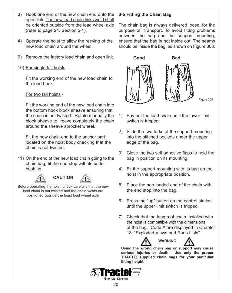
3-5 Fitting the Chain Bag
The chain bag is always delivered loose, for thepurpose of transport. To avoid fitting problemsbetween the bag and the support mounting,ensure that the bag in not inside out. The seamsshould be inside the bag as shown on Figure 308.
1) Pay out the load chain until the lower limitswitch is tripped.
2) Slide the two forks of the support mountinginto the stitched pockets under the upperedge of the bag.
3) Close the two self adhesive flaps to hold the bag in position on its mounting.
4) Fit the support mounting with its bag on thehoist in the appropriate position.
5) Place the non loaded end of the chain with the end stop into the bag.
6) Press the "up" button on the control stationuntil the upper limit switch is tripped.
7) Check that the length of chain installed withthe hoist is compatible with the dimensionsof the bag. Code # are displayed in Chapter13, “Exploded Views and Parts Lists”.
20
Good Bad
Figure 308
CAUTION
Before operating the hoist, check carefully that the newload chain is not twisted and the chain welds are
positioned outside the hoist load wheel axle.
WARNING
Using the wrong chain bag or support may causeserious injuries or death! Use only the properTRACTEL supplied chain bags for your particularlifting height.

4) ANCHORING
4-1 Anchoring the Hoist
Before proceeding to any electrical connections,a trained person must check that the supportingstructure and anchor point is strong enough forthe rated load of the hoist. If the hoist has to befitted in a location which is dangerous for theoperator, the safety precautions laid down in thelabor regulations must be implemented toremove all risks not covered in this manual.
The hoist must only be anchored using itssuspension hook or lug (optional, see Figure401). The load shall only be anchored to the loadhook. The suspension hook must be placed on afixed anchor point, such that this device engagesfully on the hook. The safety latch must closecompletely. If there is any problem with fitting thehook onto the anchor point, a sling or shackle ofthe appropriate load capacity must be placedbetween the anchor point and the hook.
Additional checks:
• The load chain length shall be sufficient forthe lifting height.
• The pendant control cable length shall be sufficient to cover the distance between the hoist and the operator position.
• Do not shorten the pendant control cable bytying knots in it.
• The load chain shall be in a good condition and not twisted particularly for the two fall version (refer to the Figure 402 and 403).
4-2 Anchoring the Trolley
If the hoist is used with a manual or electricaldrive trolley, you must check that the loadcapacity of the trolley is equal to or greater thanthe rated load of the hoist and that the beamprofile and supporting structure is strong enoughfor the rated load of the hoist.
When fitting the trolley to the beam, thesuspension yoke for hook suspension shall bealigned as shown in Figure 404(on the nextpage).
21
CAUTION
Ensure that the load chain is free of any twists such asthose caused by rolling the bottom hook through thechain. Once a 2 fall hoist is anchored and the lower hookis hanging reinspect to insure welds on chain are alignedand no twist exits.
Figure 401
Figure 403
Figure 402

Procedure for mounting the trolley on thetraversing beam (Refer to Figure 405)
1) Hold the pre-assembled trolley assembly beneath the beam, keeping a wide enough gap between the running wheels to enablethe trolley to be positioned on the beam.
2) Place two running wheels on one of the sideplates in contact with the lower flange of thetraversing beam.
3) Place the two wheels on the opposite side plate in contact with the traversing beam andturn the crossbar to bring the two side platescloser together. This will bring the four running wheels to rest on the lower flange ofthe beam. *Handles may be ordered for this process.
4) Adjust the clearance between the wheels andbeam to 1/8 in. as shown on Figure 406.
5) Tighten the securing screws on the fixing rod to prevent the assembly from moving.
6) Secure the assembly.
4-3 Anchoring the Load
• Never use the load chain of the hoist as a sling by wrapping it around the load and attaching it to the hook.
• Never mount a load on the dead end chain.• Never remove or modify the hooks’ latches.• Do not apply the load to the tip of the hook or
hook latch.• Never operate a hoist unless load slings or
other approved attachments are properly sizedand seated in the hook saddle.
• Never load the tralift TE hoist above its ratedload capacity.
Suspension yoke
beam centerline
Hook Suspension
1/8 in. (4 mm)
WARNING
The beam should be fitted with rail stops to preventthe trolley from falling off the beam.
WARNING
An excessively worn beam flange may fail. Inspectflange regularly for wear and replace if worn.
WARNING
The trolley must be properly adjusted to fit the beamflange to prevent the trolley from falling off the beam.Consult installation instructions provided bymanufacturer with trolley and take notice of anylimitations such as curve radius, etc.
Figure 404
Figure 405
Figure 406
22

5) OPERATING INSTRUCTIONS
5-1 Final Checks Before Use
• Lightly oil the load chain with SAE 120 typeoil or equivalent.
• Operate the hoist without load to run in thechain, checking it is not twisted.
• The welds on the links of the chain must always be positioned facing outside in relation to the axis of the chain sprocketwheel (Refer to Figure 501).
• Check that the paddle limit switches work correctly.
• Check that the lifting brake works correctlyby positioning a load at a short distance from the floor level and check that this loaddoes not slip.
5-2 Operating the Hoist
• Maintain a firm footing when operating the hoist.
• Check that the load is correctly secured onthe load hook and the latch closes correctly. Hook latches must be in proper condition to retain slings, chains, etc. during slack conditions.
• When moving a load, check that it is notlikely to collide with any obstacles in the surrounding area.
• The hoist must be always perpendicular to the load.
• The load must always be correctly balanced.
• Any hoist used outdoors must be appropriatelyprotected against adverse weather conditions. In outdoor use, it is essential to check daily the good condition of the electrical equipment.Also, lightly oil the load chain at least every week.
23
WARNING
It is prohibited to stand or pass beneath a suspendedload. If necessary, place a safety barrier on theground around the load area. Only unhook the loadwhen it is either on the ground floor or on anadequate strong fixed support.
CAUTION
The following precautions must be taken when performingthe various hoist operations:
Figure 501

• Do not use the load limiting device to measure a load.
• Never allow the end of the loaded chain to become slack if the load is not on a supportwhich is sufficiently strong.
• Avoid jogging operation and shock loads.
• If the hoist behaves abnormally or makesany unusual noises, the user must stop operation and inform a trained person.
As soon as the operator stops pressing thedirectional buttons, the hoist stops. If the liftingoperation is over a considerable height, it isrecommended that the stopping time is observedwhich corresponds to the duty cycle of the hoist.A red emergency stop button may be used tostop the hoist if it malfunctions.
24
NOTE:Accidental impacts to the suspended load orcatching the suspended load on fixed structuresin the working area may cause overloads.

6) INSPECTION AND MAINTENANCE
Use only TRACTEL replacement parts. Thereplacement of any part with anything other thana TRACTEL authorized replacement part mayadversely affect the function and safety of thishoist and voids the warranty. Tractel disclaimsliability for any claims of damages, whetherwarranty, property damage, personal injury ordeath arising from the use of unauthorized parts.
6-1 Load Chain Inspection
Tralift TE hoist is supplied with a case hardenedload chain, grade 80 or better suited to use onelectric chain hoists.
1) Place the hoist in it’s operating position with the load chain hanging down.
2) Count 11 links(Figure 601) and mark them.
3) Clean the links with a non-caustic solvent which is neither acidic or caustic (a white spirit type solvent is recommended).
4) Measure the 11 links and compare the measurements to Table 601.
5) Examine the load chain. The load chain mustbe replaced if any of the following is found:
• Corroded or cracked links.
• Distorted or twisted links.
• Stretched or particularly worn links.
Do not expose the chain to temperatures greaterthan 212° F (100° C) or to abuse frommechanical or chemical agents. If so, the loadchain must be replaced.
Lightly oil the load chain regularly with SAE 120type oil or equivalent.
25
WARNING
After an intensive period of use, the chain may showsigns of elongation or wear which could damage thehoist or cause the chain to break. It is thereforerecommended that the lifting chain is inspectedregularly. The chain should be measured and must bereplaced if the measurements are greater than thosegiven in the following table.
NOTE: A maintenance program should start foreach hoist immediately after it is entered intoservice. This maintenance program shouldcomply with recommendations in the applicableparts and Instruction Manual, and all pertinentFederal, State, Provincial and Local regulations.
Regular inspections should be followed for thelife of the hoist and documented by writteninspection records.
NOTE: Systematically or repeatedly stopping andstarting at the same place will cause morerapid wear of the links which stop on the loadsprocket wheel. If the chain needs to bereplaced, this must be performed by aTRACTEL approved service shop.
CAUTION
Lubricants must be handled and disposed of according tolocal, state and federal regulations.
Figure 601
Load chain sizeφ x pitch
mm
Max. L permittedlength for 11links
Fig. 23 in. (mm)
4 X 12 5.315 (135)
5 X 15 6.634 (168.5)
6.3 X 19 9.114 (231.5)
8 X 24 10.61 (269.5)
Table 601

1) Obtain a single link from the load chain to beinspected.
2) Take measurements of p (Figure 601), d4, and d5 (Figure 602).
3) Calculate dm and d5.
4) Compare the calculations to Table 602
Variables and Calculations:
dm = average diameter after wear.
d5 = d3 + d4 (sum of two links diameter together).
d3/d4 : refer to Figure 603.
26
dm = d3 + d4 < 0.9 d2
ModelRatedLoad ton
Numberof Chain
Falls
Load chain φ x pitch
mm
Diameter dFigure 601
in. (mm)
Pitch p Figure 601
in. (mm)
Max. wear on1 link p + 5%
in. (mm)
reject if dm < to 0.9d
in. (mm)
reject if d5 < to 1.8d
in. (mm)
TE 125 1/8 1 4 X 12 0.157 (4) 0.472 (12) 0.490 (12.60) 0.142 (3.60) 0.283 (7.20)
TE 250 1/4 1 5 X 15 0.197 (5) 0.591 (15) 0.620 (15.75) 0.177 (4.50) 0.354 (9)
TE 500 1/2 2 5 X 15 0.197 (5) 0.591 (15) 0.620 (15.75) 0.177 (4.50) 0.354 (9)
TE 500 1/2 1 6.3 X 19 0.248 (6.3) 0.748 (19) 0.785 (19.95) 0.223 (5.67) 0.446 (11.34)
TE 1000 1 2 6.3 X 19 0.248 (6.3) 0.748 (19) 0.785 (19.95) 0.223 (5.67) 0.446 (11.34)
TE 1000 1 1 8 X 24 0.315 (8) 0.945 (24) 0.992 (25.20) 0.283 (7.20) 0.567 (14.40)
TE 2000 2 2 8 X 24 0.315 (8) 0.945 (24) 0.992 (25.20) 0.283 (7.20) 0.567 (14.40)
Figure 602
Figure 603
Table 602
WARNING
After an intensive period of use, the chain may showsigns of elongation or wear which could damage thehoist or cause the chain to break. It is thereforerecommended that the lifting chain is inspectedregularly. The chain should be measured and must bereplaced if the measurements are greater than thosegiven in the following table.
ADVANCED LOAD CHAIN INSPECTION
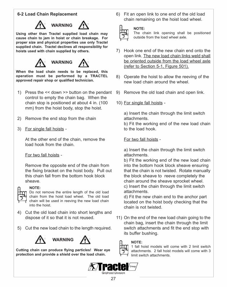
6-2 Load Chain Replacement
1) Press the << down >> button on the pendantcontrol to empty the chain bag. When the chain stop is positioned at about 4 in. (100 mm) from the hoist body, stop the hoist.
2) Remove the end stop from the chain
3) For single fall hoists -
At the other end of the chain, remove the load hook from the chain.
For two fall hoists -
Remove the opposite end of the chain from the fixing bracket on the hoist body. Pull outthis chain fall from the bottom hook block sheave.
4) Cut the old load chain into short lengths anddispose of it so that it is not reused.
5) Cut the new load chain to the length required.
6) Fit an open link to one end of the old load chain remaining on the hoist load wheel.
7) Hook one end of the new chain end onto theopen link. The new load chain links weld shallbe oriented outside from the load wheel axle(refer to Section 5-1, Figure 501).
8) Operate the hoist to allow the reeving of the new load chain around the wheel.
9) Remove the old load chain and open link.
10) For single fall hoists -
a) Insert the chain through the limit switch attachments.b) Fit the working end of the new load chainto the load hook.
For two fall hoists -
a) Insert the chain through the limit switch attachments.b) Fit the working end of the new load chaininto the bottom hook block sheave ensuring that the chain is not twisted. Rotate manuallythe block sheave to reeve completely the chain around the sheave sprocket wheel.c) Insert the chain through the limit switch attachments.d) Fit the new chain end to the anchor part located on the hoist body checking that the chain is not twisted.
11) On the end of the new load chain going to thechain bag, insert the chain through the limit switch attachments and fit the end stop with its buffer bushing.
27
WARNING
Using other than Tractel supplied load chain maycause chain to jam in hoist or chain breakage. Forproper size and physical properties use only Tractelsupplied chain. Tractel declines all responsibility forhoists used with chain supplied by others.
WARNING
When the load chain needs to be replaced, thisoperation must be performed by a TRACTELapproved repair shop or qualified technician.
WARNING
Cutting chain can produce flying particles! Wear eyeprotection and provide a shield over the load chain.
NOTE:The chain link opening shall be positionedoutside from the load wheel axle.
NOTE:Do not remove the entire length of the old loadchain from the hoist load wheel. The old loadchain will be used in reeving the new load chaininto the hoist.
NOTE:1 fall hoist models will come with 2 limit switchattachments. 2 fall hoist models will come with 3limit switch attachments.

6-3 Hook Inspection
On tralift TE range, the upper suspension hook isfixed and mounted perpendicular to the hoist.Only the load hook has ball bearings and canswivel. The suspension and load hooks shouldbe inspected regularly for wear. Damaged safetylatches must be replaced immediately. The hooksshould be frequently checked to ensure there isno trace of corrosion, impact, distortions orcracks or elongation.
Inspect the hooks for the following:
1) The load hooks should rotate freely eve whenunder load.
2) Latches should be appropriately secured in place and open/close properly.
3) Any signs of cracking (use of magnetic particle or dye penetrents are recommended).
4) Any indications of deformation including:
a) Throat Width
A maximum movement of 10% of the hookopening distance, “A” in Figure 604, is acceptableaccording to ANSI B30.10.
If the maximum opening distance "A" is greaterthan the values in Table 602, the hook shall bereplaced immediately before any further use.This operation must be performed by acompetent person or a service shop approved byTRACTEL.
b) Twisting
Check for twisting of the hook (Figure 605).Discard if twisted over 10°.
28
Model Rated Load (ton)
Dimension "A" maximum in. (mm)
TE 125 1/8 1.0 (25.3)
TE 250 1/4 1.0 (25.3)
TE 500 1/2 1.17 (29.7)
TE 1000 1 1.56 (39.6)
TE 2000 2 1.73 (44)
Table 602
Figure 604
Figure 605

6-4 Limit Switch
Note: All of the newly designed Tralift TE from 2004 and on will have paddle limit switches instead of a screw drive limit switch. It is a simple external system and easy to install.
1) The paddle limit switch is located on the bottom of the hoist (Figures 606 & 607) where the chain enters and exits the hoist. It requires no adjustment.
2) Paddle limit switch engages when a spring loaded aluminum stopper compresses the limit switch (Figure 608).
3) The assembly of the spring loaded stopper (Figure 609). Aluminum stopper should have the smaller diameter section facing the spring.
29
Figure 606
Figure 607
WARNING
Correct assembly is very important for the limitswitch to work properly.
Upper
Lower
Figure 608
Figure 609

6-5 Brake Inspection & Adjustment
As the hoist is used, wear of the brake liningsmay cause the hoist to slip and not hold the load.If slipping occurs, the load should be immediatelylowered to the ground. The brake should bechecked and adjusted by a qualified person orrepair shop who is approved by TRACTEL towork on the electric hoist.
Specifications
• The normal gap between the disc support plate linings and the solenoid is between 0.020 to 0.040 in. (0.5 to 1 mm) maximum.
• In normal working conditions, the brake working time is between 1000 to 1500 hoursbefore needing adjustment.
Refer to Figure 606 during the procedure.
1) Insert the 0.020 in.(0.5 mm) spacer betweenthe disc support plate(#2) and the solenoid(#1). If the spacer DOES NOT fit, the brake gap is not wide enough. Continueto the “Brake Gap Adjustment Procedure”.
2) Insert the 0.040 in.(1.0 mm) spacer betweenthe disc support plate(#2) and the solenoid(#1). If the spacer DOES fit, the brake gap is too wide or the brake is worn down excessively. Continue to the “Brake Gap Adjustment Procedure”.
Brake Gap Adjustment(Refer to Figure 610)
1) Disconnect the power supply from the hoist.
2) Open the hoist by removing the cover opposite to the power supply. The brake is on the right side.
3) Remove the two safety plates(#3) by unscrewing the four fixing screws and washers(#4).
4) Insert a 0.02 in. (0.5 mm) spacer between thesolenoid (#1) and the support plate(#2). Tighten the four adjusting screws with nuts item(#5) in the same way. The gap is then correctly adjusted.
5) Release the four adjusting screws(#5) by 1/6of a turn and remove the spacer. Tighten again the four screws(#5)by 1/6 of a turn to put them back into position.
6) Reposition the two safety plates(#3) and tighten the four fixing screws and washers(#4).
7) Replace the cover and connect the hoist to its power supply.
30
CAUTION
Never put oil or grease on the brake friction surface. Wipeoff and clean any trace of lubricant which may beobserved.
NOTE:Any adjustment to the brake should be donewithout a load on the hoist.
Figure 610
1. Solenoid, 2. Support plate 3. Safety plates
4. Fixing screws 5. Adjusting screws
NOTE:For preliminary check of brake wear, you willneed 0.020 in. and 0.040 in. (0.5 mm and 1 mm)spacers.
NOTE:Badly worn, scratched, or deformed brake discsmust be replaced. Refer to the “Brake DiscReplacement Procedure” on the next page.

Brake Disc Replacement (Refer to Figure 611)
1) Disconnect the power supply from the hoist
2) Put the hoist frame in vertical position in order to get the brake assembly in horizontalposition.
3) Remove the two safety plates (#24.6) by unscrewing the four fixing screws and washers (#24.7/24.8).
4) Remove the four nuts (#24.9) which will allowyou to slide out the solenoid (#24.10) and theeight springs (#24.4/24.5). When you remove the solenoid, be careful not to damage the electrical wires.
5) Remove the disc support plate (#24.3) and then the brake disc (#24.2).
6) Fit the new brake disc and brake assembly.
7) Re-adjust the brake gap (refer to the “Brake Gap Adjustment Procedure” on Page 31). A normal gap should be between 0.020 to 0.040 in. (0.5 to 1 mm).
8) Reposition the two safety plates (#24.6) and tighten the four fixing screws and washers (#24.7/24.8).
31
NOTE:If after the brake adjustment the gap betweenthe solenoid and the disc support plate remainsgreater than 0.040 inches (1mm), the brake discmust be replaced.
Figure 611

7) WARNINGS AGAINST HAZARDOUSOPERATIONS
Our tralift TE shall be used in accordance withthis instruction manual. It is important to draw theattention of users to the following warnings:
• Never use the hoist, even occasionally, for lifting people.
• Never use the hoist under an enviroment which does not comply with its specificationsor with this instructions manual.
• Never lift a load heavier than the rated load indicated on the hoist.
• Never use the hoist in dangerous conditions for the operator.
• Never use a hoist upside down (inverted).
• Never suspend the hoist by its load chain hook or its electrical cables.
• Never start up the operation without ensuringthat all the safety devices on the hoist are in place and operating correctly. Checks must be made to ensure that the limit switches are in the required locations to stop the hoist automatically in total safety.
• Never connect the hoist without checking that the main electrical installation is accordancewith a relevant safety regulation.
• Never drag a load on the floor.
• Never force the hoist movements if the load chain cannot operate freely.
• Never use the pendant control with the controls reversed as this could cause dangerous operating errors and deactivate the limit switches.
• Never mount a load on the dead end chain.
• Transport of hot molten material may requireadditional equipment or devices refer to ANSI Z241.2.
• Never use the load chain as a sling.
• Never intentionally cause or leave a suspended load to swing.
• Never stand or pass beneath a suspended load.
• Never mount the hoist on a unsuitable support.
• Never remove or modify the hooks’ latches.
• Never remove the paddel limit switches.
• Never force the hoist suspension hook or lug(optional) to make hoist rotate on its axis.
• Never touch moving parts in operation.
• Never move a hoist suspended from a chain traveling trolley other than operating the hand chain provided for that purpose.
8) HEALTH AND SAFETY AT WORK
It is the responsibility of every company to ensurethat its employees have been fully and properlytrained in the safe operation of the equipment.Before using the equipment, check all safetydevices of the hoist are in place and operatecorrectly (Chapter 10).
32

9) REMOVING FROM SERVICE AND STORAGE
Never release the load from the hoist if this loadis not supported properly.
• The hoist may be stored without load providing it is placed indoors in a cool, dry area.
• Never allow an unqualified person who has not read these instructions to use the hoist.
The control cable being fitted with a plug inconnector, it is possible to disconnect thependant control from the hoist to prevent the hoistto be used by this unqualified person (refer toFigure 901).
10) Safety Devices
Tralift TE hoists provide the following safetyequipment as standard:
• Friction clutch limiting device acting as a safety limit switch.
• Paddle limit switches.
• Asbestos free brake separate from the liftingmotor.
• Latches on the suspension and load hooks.
• Mechanical and electrical locking of the pendant control preventing simultaneous operation of the “up-down” controls (and “left-right” buttons when the hoist is supplied withan elctric drive trolley).
• 48 V low voltage electrical control equipment.
• Emergency stop button on the pendant control station. In the event of operating problems, emergency stop is obtained by simply pressing the red button on the pendant control. (To restart the device, the red button must be released by turning it in the direction of the red arrows marked on thebutton).
• A phase protector which prevents reverse operation.
33
Figure 901
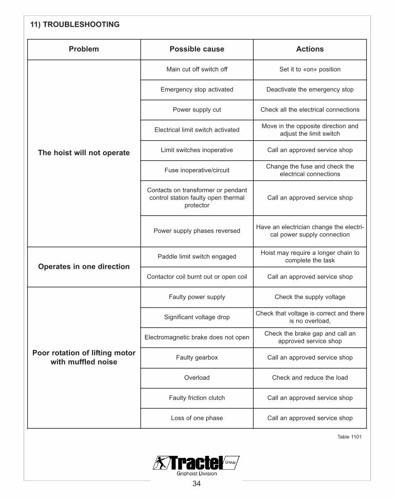
11) TROUBLESHOOTING
34
Problem Possible cause Actions
The hoist will not operate
Main cut off switch off Set it to «on» position
Emergency stop activated Deactivate the emergency stop
Power supply cut Check all the electrical connections
Electrical limit switch activated Move in the opposite direction andadjust the limit switch
Limit switches inoperative Call an approved service shop
Fuse inoperative/circuit Change the fuse and check theelectrical connections
Contacts on transformer or pendantcontrol station faulty open thermal
protector Call an approved service shop
Power supply phases reversed Have an electrician change the electri-cal power supply connection
Operates in one directionPaddle limit switch engaged Hoist may require a longer chain to
complete the task
Contactor coil burnt out or open coil Call an approved service shop
Poor rotation of lifting motorwith muffled noise
Faulty power supply Check the supply voltage
Significant voltage drop Check that voltage is correct and thereis no overload,
Electromagnetic brake does not open Check the brake gap and call anapproved service shop
Faulty gearbox Call an approved service shop
Overload Check and reduce the load
Faulty friction clutch Call an approved service shop
Loss of one phase Call an approved service shop
Table 1101
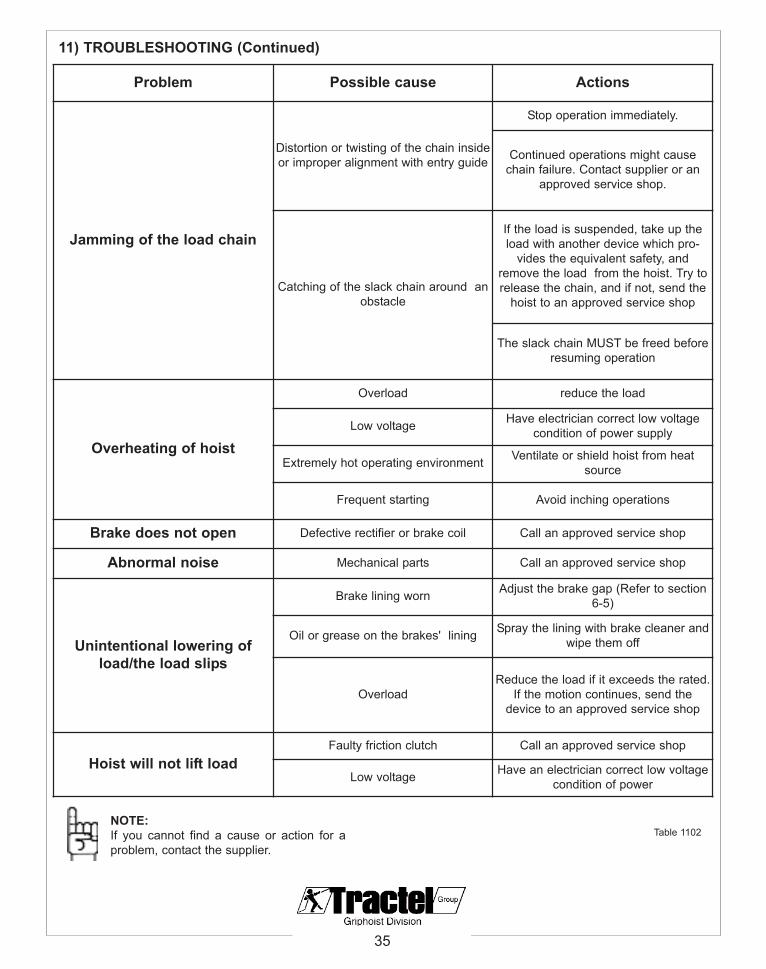
11) TROUBLESHOOTING (Continued)
35
NOTE:If you cannot find a cause or action for aproblem, contact the supplier.
Problem Possible cause Actions
Jamming of the load chain
Distortion or twisting of the chain insideor improper alignment with entry guide
Stop operation immediately.
Continued operations might causechain failure. Contact supplier or an
approved service shop.
Catching of the slack chain around anobstacle
If the load is suspended, take up theload with another device which pro-
vides the equivalent safety, andremove the load from the hoist. Try torelease the chain, and if not, send the
hoist to an approved service shop
The slack chain MUST be freed beforeresuming operation
Overheating of hoist
Overload reduce the load
Low voltage Have electrician correct low voltagecondition of power supply
Extremely hot operating environment Ventilate or shield hoist from heatsource
Frequent starting Avoid inching operations
Brake does not open Defective rectifier or brake coil Call an approved service shop
Abnormal noise Mechanical parts Call an approved service shop
Unintentional lowering ofload/the load slips
Brake lining worn Adjust the brake gap (Refer to section6-5)
Oil or grease on the brakes' lining Spray the lining with brake cleaner andwipe them off
OverloadReduce the load if it exceeds the rated.
If the motion continues, send thedevice to an approved service shop
Hoist will not lift loadFaulty friction clutch Call an approved service shop
Low voltage Have an electrician correct low voltagecondition of power
Table 1102

36
12) TABLE OF INSPECTIONS AND LUBRICATION CHECKS
The checks mentioned in the following table are additional to the periodic inspections required by ANSI/ASME B30.16. This table is given for information only, for use of the hoist, class H4, fornormal operating conditions. Inspections should be performed more frequently if the equipment is used for heavy or severe service, or is constantly operated at or near maximum rated load.
Checks and Inspections Frequency Person
Check general condition of the hoist
daily
operator
Visual inspection of load chain and hooks operator
Check the brake is working properly operator
Cleaning and lubrication of load chain
monthly
operator
Check that paddle limit switches are working properly operator
Check that electrical connections in hoist and trolley are ingood condition operator
Check chain bag and its attachment operator
Lubrication of the sheave and rotation axles on the load hook
quarterly
operator
Measurement of load chain wear approved service shop
Measurement of wear and opening on load hook and checklatches operate correctly approved service shop or operator
Visual inspection of trolley side plates (cracks, distortion) operator
Wear of brake lining
six months
approved service shop
Check friction clutch limiting device approved service shop
Vision check of trolley wheels and hand chain operator
General inspection of pars of the hoist subject to wear andadjustment of brake friction clutch-limiting device and limit
switchesyearly approved service shop
Table 1201

1. NOT operate a damaged, malfunctioning or unusually performing hoist.
2. NOT operated the hoist until you have thoroughly read and understood the manufacturer’s Operating and Maintenance Instructions or Manuals.
3. NOT operate a hoist which has been modified without the manufacturer’s approval or without certification that it is in conformitywith ANSI/AMSE B30 volumes.
4. NOT lift more than rated load for the hoist. 5. NOT use hoist with twisted, kinked, damaged, or worn load chain or
wire rope.6. NOT use the hoist to lift, support, or transport people.7. NOT lift loads over people.8. NOT operate a hoist unless all persons are and remain clear of the
supported load.9. NOT operate unless load is centered under hoist.10. NOT attempt to lengthen the load wire rope or chain or repair
damaged load wire rope or chain.11. Protect the hoist’s load wire rope or chain from weld splatter or other
damaging contaminents.12. NOT operate hoist when it is restricted from forming a straight line
from hook to hook in the direction of loading.13. NOT use load wire rope or chain as a sling, or wrap load wire rope or
chain around load.14. NOT apply the load to the tip of the hook or to the hook latch.15. NOT apply load unless load chain is properly seated in the chain
wheel(s) or sprocket(s) or wire rope is properly seated in its groove(s).16. NOT apply load if bearing prevents equal loading on all load
supporting ropes chains.17. NOT operate beyond the limits of the load wire rope or chain travel.18. NOT leave load supported by the hoist unattended unless specific
precautions have been taken.19. NOT allow the load wire rope, chain or hook to be used as an
electrical or welding ground.20. NOT allow the load wire rope, chain or hook to be touched by a live
welding electrode.21. NOT remove or obscure the warnings on the hoist22. NOT operate a hoist on which the safety placards or decals are
missing or illegible.23. NOT operate a hoist unless it has been securely attached to a suitable
support.24. NOT operate a hoist unless load slings or other approved single
attachments are properly sized and seated in the hook saddle.25. Take up slack carefully - make sure load is balanced and load holding
action is secure before continuing.26. Shut down a hoist that malfunctions or performs unusually and report
such malfunction.27. Make sure hoist limit switches function properly.28. Warn personnel of an approaching load.
1. Maintain a firm footing or be otherwise secured when operating the hoist.
2. Check brake function by tensioning the hoist prior to each lift operation.
3. Use hook latches. Latches are to retain slings, chains, etc. under slack conditions only.
4. Make sure the hook latches are closed and not supporting any parts of the load.
5. Make sure the load is free to move and will clear all obstructions.6. Avoid swinging the load or hook.7. Make sure hook travel is in the same direction as shown on the
controls.8. Inspect the hoist regularly, replace damaged or worn parts, and keep
appropriate records of maintenance.9. Use the hoist manufacturer’s recommended parts when repairing the
unit.10. Lubricate load wire rope or chain per hoist manufacturer’s
recommendations.11. NOT use the hoist load limiting or warning device to measure load.12. NOT use limit switches as routine operating stops unless allowed by
manufacturer. They are emergency devices only.13. NOT allow your attention to be diverted from operating the hoist.14. NOT allow the hoist to be subjected to sharp contact with other hoists,
structures, or objects through misuse.15. NOT adjust or repair the hoist unless qualified to perform such
adjustments or repairs.
37
13) RECOMMENDED PRACTICESELECTRIC AND AIR POWERED HOISTS
Because the manufacturer has no direct control over the hoist and its operation, conformance withgood safety practice is the responsibility of the user and operating personnel. ANSI/ASME B30.16has been used as a guide in preparing this list of SHALL’s and SHALL NOT’s. Ask yoursupervisor for a copy. Each is identified according to ANSI/NEMA Z535.4 with either the signalwork CAUTION or WARNING to indicate the degree of seriousness.
DISCLAIMERUnder no circumstances does the Hoist Manufacturers Institute (HMI) assume any liability for the use of these voluntary recommendations, and no warranty whatsoever is made in connection with them. The recommendations do not take precedence over existingplant safety rules and regulations, OSHA regulations or instructions issued by the Hoist Manufacturer. It is the user’s intent to absolve and protect HMI from any and all liability, in tort or otherwise.
CAUTION
Improper operation of a hoist can create a potentiallyhazardous situation which, if not avoided, could result in
minor or moderate injury. To avoid such a potentiallyhazardous situation, the operator shall:
WARNINGImproper operation of hoist can create a potentiallyhazardous situation which, if not avoided, could resultin death or serious injury. To avoid such a potentiallyhazardous situation, the operator shall:

1-1
12
34
5.15.25.3
5.45.55.67.1
7.2
7.37.4
7.5
7.7
7.8
10.1
10.2
17.1
7.6
56
78
910
1112
1314
1516
1718
19.1
17.2
1917.3
17.4
17.5
14.1
15.1
15.2
15.3
22.1
22.2
12.1
12.2
12.3
12.4
12.5
26.1
26.2
7.9
7.10
7.11
7.12
7.13
7.14
7.15
4.1
4.2
4.3
36.1
36.2
40.1
2.1
2.2
2.3
25.1
25.2
2021
2223
2425
2627
2829
3130
32
3334353637394041 38
Tralift TE USA All capacities
Spare parts
group :
ref. : -rev. n° : -date : 06/04page : 1/10
Parts List
38

39
14) EXPLODED VIEWS AND PARTS LISTS
Position DescriptionTRACTEL CODE
125 1 Fall 250 1 Fall 500 2 Fall 500 1 Fall 1000 2 Fall 1000 1 Fall 2000 2 Fall1 Technical Data Plate
24472 24482 24482 24492 24492 24502 245021.1 Screws M3 x 62 Motor Side Cover
15042 15052 15052 15062 15062 15072 150722.1 Washer Ø 6 mm2.2 Spring-Type Washer Ø 6 mm2.3 Screw M6 x 603 Motor Cover Seal 127205 127245 127245 127285 127285 127325 1273254 Mounting Rail Assembly
8731 8731 8731 8731 8731 8731 8731 4.1 Washer Ø 4 mm4.2 Spring-Type Washer Ø 4 mm4.3 Screw M4 x 125 Motor Casing
15122 15132 15132 15142 15142 15152 15152
5.1 Screw5.2 Spring Type Washer5.3 Washer5.4 Bearing Retainer5.5 Spring-Type Washer5.6 Screw6 Motor Casing Seal 127215 127255 127255 127295 127295 127335 1273357.0 Motor Complete
24342 -1 Speed
24352 -2 Speed
24362 -1 Speed
24372 -2 Speed
24382 -1 Speed
23492-2 Speed
24382 -1 Speed
23492 -2 Speed
24402 -2 Speed
24412 -2 Speed
24412 -2 Speed
7.1 Pin A6 x 107.2 Motor Stator7.9 Circlip for Shaft 7.10 Bearing7.11 Circlip for Shaft7.12 Motor Rotor One Speed7.13 Bearing7.14 Lock Washer7.15 Circle Nut8 Chain Bag Refer To Page 499 Chain Bag & Bucket Bracket 1624210 Chain Sprocket Wheel
15602 15612 15612 15622 15622 15632 15632 10.1 Ball Bearing10.2 Circlips11 Kit Chain Guide 15562 15572 15572 15582 15582 15592 1559212 Gear Casing12.1 Screw
15682 15692 15692 15702 15702 15712 1571212.2 Spring-Type washer12.3 Washer12.4 Bearing12.5 Pin A6 x 12
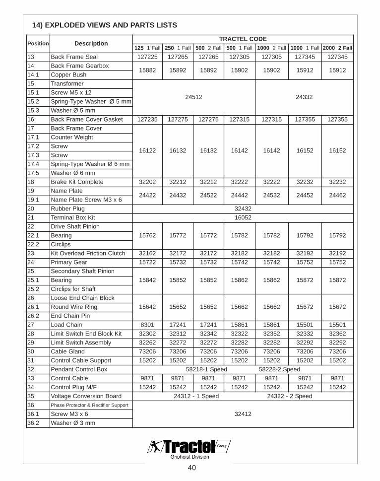
40
14) EXPLODED VIEWS AND PARTS LISTS
Position DescriptionTRACTEL CODE
125 1 Fall 250 1 Fall 500 2 Fall 500 1 Fall 1000 2 Fall 1000 1 Fall 2000 2 Fall13 Back Frame Seal 127225 127265 127265 127305 127305 127345 12734514 Back Frame Gearbox
15882 15892 15892 15902 15902 15912 1591214.1 Copper Bush15 Transformer
24512 24332 15.1 Screw M5 x 1215.2 Spring-Type Washer Ø 5 mm15.3 Washer Ø 5 mm16 Back Frame Cover Gasket 127235 127275 127275 127315 127315 127355 12735517 Back Frame Cover
16122 16132 16132 16142 16142 16152 16152
17.1 Counter Weight17.2 Screw17.3 Screw17.4 Spring-Type Washer Ø 6 mm 17.5 Washer Ø 6 mm18 Brake Kit Complete 32202 32212 32212 32222 32222 32232 3223219 Name Plate
24422 24432 24522 24442 24532 24452 24462 19.1 Name Plate Screw M3 x 620 Rubber Plug 3243221 Terminal Box Kit 1605222 Drive Shaft Pinion
15762 15772 15772 15782 15782 15792 1579222.1 Bearing22.2 Circlips23 Kit Overload Friction Clutch 32162 32172 32172 32182 32182 32192 3219224 Primary Gear 15722 15732 15732 15742 15742 15752 1575225 Secondary Shaft Pinion
15842 15852 15852 15862 15862 15872 1587225.1 Bearing25.2 Circlips for Shaft26 Loose End Chain Block
15642 15652 15652 15662 15662 15672 1567226.1 Round Wire Ring26.2 End Chain Pin27 Load Chain 8301 17241 17241 15861 15861 15501 1550128 Limit Switch End Block Kit 32302 32312 32342 32322 32352 32332 3236229 Limit Switch Assembly 32262 32272 32272 32282 32282 32292 3229230 Cable Gland 73206 73206 73206 73206 73206 73206 7320631 Control Cable Support 15202 15202 15202 15202 15202 15202 15202 32 Pendant Control Box 58218-1 Speed 58228-2 Speed33 Control Cable 9871 9871 9871 9871 9871 9871 9871 34 Control Plug M/F 15242 15242 15242 15242 15242 15242 1524235 Voltage Conversion Board 24312 - 1 Speed 24322 - 2 Speed36 Phase Protector & Rectifier Support
32412 36.1 Screw M3 x 636.2 Washer Ø 3 mm
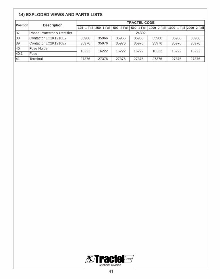
41
14) EXPLODED VIEWS AND PARTS LISTS
Position DescriptionTRACTEL CODE
125 1 Fall 250 1 Fall 500 2 Fall 500 1 Fall 1000 2 Fall 1000 1 Fall 2000 2 Fall37 Phase Protector & Rectifier 2430238 Contactor LC1K1210E7 35966 35966 35966 35966 35966 35966 35966 39 Contactor LC2K1210E7 35976 35976 35976 35976 35976 35976 35976 40 Fuse Holder
16222 16222 16222 16222 16222 16222 16222 40.1 Fuse41 Terminal 27376 27376 27376 27376 27376 27376 27376

Tralift TE USA Kits
- Spare parts
group :
ref. : -rev. n° : -date : 06/04page : 2/5
Parts List
29.1 29.2 29.3 29.4 29.5
29.6
29.7
29.8
29.9
31.1 31.2 31.3
31.4
31.5
31.6
29 - End limit switch 31 - Control plug
34.1
34.2
34 - Control plug
35.1 35.2 35.3 35.4 35.5 35.6 35.7
35 - Voltage conversion board

43
14) EXPLODED VIEWS AND PARTS LISTS Limit Switch, Control Plugs & Voltage Conversion Board
Position DescriptionTRACTEL CODE
1251 Fall
2501 Fall
5002 Fall
5001 Fall
1000 2Fall
10001 Fall
2000 2Fall
29 Limit Switch End Block Kit
32302 32312 32342 32322 32352 32332 32362
29.1 Bung
29.2 Screws M2 x 12
29.3 Washer
29.4 Microswitch
29.5 Main Block
29.6 Washer
29.7 Screw
29.8 Screw M4 x 10
29.9 Limit Switch End Block
31 Control Cable Support Kit
15202
31.1 Screw
31.2 Washer
31.3 Ring Attachment
31.4 Suspension Ring
31.5 Hook Connector
31.6 Wire Rope Fixation
34 Control Plug M/F Kit
1524234.1 Flat Cable Gland
34.2 Round Cable Gland
35 Voltage Conversion Board kit
24312 - 1 Speed - All Models
24322 - 2 Speed - All Models
35.1 3-Pin Plug
35.2 6-Pin Plug
35.3 Screw M3 x 18
35.4 Printed Circuit Board
35.5 Isolative Space
35.6 Isolative Plate
35.7 Mounting Plate
- Pendant Clip 088586 - (Part Not Included In Kits)

Tralift TE USA Suspension kits Spare parts
group :
ref. : -rev. n° : -date : 06/04page : 1/4
Parts List
1
2
3
4
5
6
78
9
10
11
1 2 3 4 5 6
9
8
7
1 2 3 4 5
6
78
9
10
11
12
11
1
2
3
4
5
67
8
9
10
1 2 3 4
Superior hook Direct coupling
Bottom hook assembly 1 fall
Safety latch
Bottom hook assembly 2 falls

45
Position DescriptionTRACTEL CODE
125 1 Fall 250 1 Fall 500 2 Fall 500 1 Fall 1000 2 Fall 1000 1 Fall 2000 2 Fall
Upper Hook1 Upper Hook
31982 31992 32062 32002 32072 32012
32082
2 Set screw M5 x 10 n/a
3 Fastening Plate
32082
4 Suspension Adapter
5 String-Type Pin 4 x 30 n/a
6 Nut 31982 31992
32062
32002
32072
32012
7 Cotter Pin
n/a n/a n/a n/a 8 Suspension Pin
9 Dead End Block
10 Screw 31982 31992 32002 32012
11 Suspension Stud n/a n/a n/a n/a
Direct Coupling1 Washer
33582 33612 33592 33622 33602
33632
2 Threaded Suspension Shaft
3 Suspension Adapter
4 String-type pin 4 x 30 n/a
5 Hex Nut 33582 33592
33622
33602
6 Split Pin
n/a 33612 n/a n/a 7 Suspension Pin
8 Connecting Block
9 Screw 33582 33592 33602
10 Suspension Stud n/a n/a n/a n/a
11 Split Pin 4x2033582 33612 33592 33602
12 Suspension Shaft
14) EXPLODED VIEWS AND PARTS LISTS One Fall & Two Fall Suspension Kits

46
Position DescriptionTRACTEL CODE
125 1 Fall 250 1 Fall 500 2 Fall 500 1 Fall 1000 2 Fall 1000 1 Fall 2000 2 Fall
Bottom Hook Assembly 1 Fall1 Screw M5 x 20
32092 32102 32112 32122
2 Spring-Type Washer Ø 5 mm
3 Bottom Hook Black
4 Chain Pin
5 Spring-Type Pin
6 Prevailing Torque Type Nut M5
7 Lower Hook
8 Thrust Bearing 8100
9 Hexagon Slotted Nut
Bottom Hook Assembly 2 Falls1 Screw M6 x 40
32132 32142 32152
2 Bearing 80104
3 Idle Sheave
4 Bottom Hook Black
5 Prevailing Torque Type Nut M6
6 Lower Hook
7 Thrust Bearing 8103
8 Spring-type Pin 4 x 28 mm
9 Hexagon Slotted Nut M16
10 Spring-Type Washer Ø 6 mm
11 Screw M6 x 20
Upper & Lower Safety Latch1 Prevailing Torque Type Nut M4
32022 32022 32032 32032 32042 32042 320522 Safety Latch
3 Double Spring
4 Screw
14) EXPLODED VIEWS AND PARTS LISTS One Fall & Two Fall Load Kits

47
Position DescriptionTRACTEL CODE
1251 Fall
2501 Fall
5002 Fall
5001 Fall
10002 Fall
10001 Fall
20002 Fall
18 Brake Complete Kit
32202 32212 32212 32222 32222 32232 32232
18.1 Brake Bolt
18.2 Spring-Type Washer Ø 6 mm
18.3 Screw M6 x 20
18.4 Brake Friction Disk
18.5 Brake Armature
18.6 Brake Spring
18.7 Position Fixing Spring
18.8 Spring-Type Washer Ø 4 mm
18.9 Screw M4 x 4
18.10 Brake Lock Plate
18.11 Prevailing Torque Type Nut M5
18.12 Brake Field Sub Assembly
18.13 Brake Base Plate
21 Terminal Box Kit
16052
21.1 Terminal Frame
21.2 Terminal
21.3 Screw M3 x 6
21.4 Washer Ø 3 mm
21.5 Screw M5 x 12
21.6 Spring-Type Washer Ø 5 mm
23 Overload friction Clutch Kit
32162 32172 32172 32182 32182 32192 32192
23.1 Spline Hub
23.2 Adjusting Washer
23.3 Belleville Spring Washer
23.4 Clutch Friction Disk
23.5 First Stage Gear
23.6 Clutch Carrier
23.7 Adjusting Nut
28 End Block Limit Switch Kit
32302 32312 32342 32322 32352 32332 3236228.1 Stoper
28.2 Dead End Stoper
28.3 Spring
14) EXPLODED VIEWS AND PARTS LISTS Brake, Terminal Box, Friction Clutch & Limit Switch

Tralift TE USA Kits
Spare parts
group :
ref. : -rev. n° : -date : 06/04page : 1/5
Parts List
18.1 18.2 18.3 18.4 18.5 18.6 18.7
18.10
18.8
18.9
18.1118.12
18.13
23.1 23.2 23.3 23.4 23.5 23.6 23.7 28.1
28.2
28.3
21.221.1
21.321.421.521.6
18 - Brake 21 - Terminal box
23 - Overload friction clutch 28 - End block limit switch

Hoist Model Hoist InfoHeight of Lift, ft (m)
3 ft to 20 ft(1m to 6m)
20 ft to 39 ft(7m to 12m)
39 ft to 59 ft(13m to 18m)
60 ft to 79 ft(19m to 24m)
80 ft to 115 ft(25m to 35m)
125
1 Fall
16272 163424 x 12
Bag SupportCode: 16242
250
1 Fall
16282 16342 163525 x 15
Bag SupportCode: 16242
500
2 Fall
16282 16342 16352 N/A5 x 15
Bag SupportCode: 16242
500
1 Fall
16282 16352 163026.3 x 19
Bag SupportCode: 16252
1000
2 Fall
16282 16352 105307 N/A6.3 x 19
Bag SupportCode: 16252
1000
1 Fall
16342 16302 1053178 x 24
Bag SupportCode: 16252
2000
2 Fall
16342 16302 105317 N/A8 x 24
Bag SupportCode: 16252
49
14) EXPLODED VIEWS AND PARTS LISTS Chain Bag Specifications
WARNINGUsing the wrong chain bag or support may causeserious injuries or death! Use only the properTRACTEL supplied chain bags for your particularlifting height.

© Copyright - All rights reserved
TRACTEL Inc.GRIPHOIST Division
Main Office:110, Shawmut RoadCanton, MA 02021Tel: 800-421-0246Fax: 781-828 3642
TRACTEL LTDGRIPHOIST Division11020 Mirabeau St
Anjou QUEBEC, H1J 2S3Tel. +1 (514) 493 3332 Fax. +1 (514) 493 3342
TRACTEL Inc.GRIPHOIST Division
Branch Office: 315 Cloverleaf Dr. Building E
Baldwin Park, CA 91706Tel. +1 (626) 937 6727Fax. +1 (626) 937 6730


![MANUEL DE L’OPÉRATEUR - Vulcan Hoist - Palan...ou à pluisuers poutres, pont roulant à palan pour chariots]; et la norme AISI/ASME B30.11, Monorails and Underhung Cranes [Monorails](https://img.dokumen.tips/doc/110x75/60f90d5bea48d402783bd98d/manuel-de-laoprateur-vulcan-hoist-palan-ou-pluisuers-poutres-pont.jpg)


