Embed Size (px)
Citation preview

MapRoad PMS Operational Manuals Web Applications
Pavement Management System Version 4.1
Training Manual for Pavement Management System Page 2 of 75
Purpose of this Document The purpose of this document is to provide an overview of the Pavement Management System web application functionality and provide support content demonstrating the system use. Revision History
Version Description Author Date
1 First Draft (Subsection of MR/PMS 1.4) OS 20/02/2012
2 Second Draft (revision) AD 09/03/2012
3 Third Draft (Revised and updated standard) PMS 1.9 OS 30/01/2013
4 Fourth Draft (Revised and updated) PMS 3.0 ROL 09/01/2015
5 Fifth Draft (inclusion of all PMS applications) PMS 3.2 ROL 08/05/2015
6 Sixth Draft (revised and updated) PMS 4.0 MR 25/08/2016
7 Update to reflect PMS 4.1 development ROL 23/11/2016

Training Manual for Pavement Management System Page 3 of 75
Table of Contents
1 Introduction to the Pavement Management System ........................................................................ 8
1.1 Reports & Dashboards ............................................................................................................. 9
2 Main Viewer ..................................................................................................................................... 10
2.1 Logging in ............................................................................................................................... 10 2.2 Site Layout .............................................................................................................................. 11 2.3 PMS Features ......................................................................................................................... 12
Map Layers ................................................................................................................ 12 Legend ....................................................................................................................... 13 Printing ...................................................................................................................... 13 Road Information ...................................................................................................... 14 Gazetteer ................................................................................................................... 15 Time slider ................................................................................................................. 15 PMS Help ................................................................................................................... 15 Using the Toolbar Features ....................................................................................... 16
2.4 Works ..................................................................................................................................... 19 View Works Job ......................................................................................................... 19 Create Works Job ...................................................................................................... 22 Create Multi-Segment Works Job ............................................................................. 27 Export Works Job ...................................................................................................... 30 Delete Works Job ...................................................................................................... 30
2.5 Roads Programme .................................................................................................................. 31 View Roads Programme ............................................................................................ 31 Create Roads Programme ......................................................................................... 32 Submit Roads Programme to DTTAS ......................................................................... 35 Delete Roads Programme ......................................................................................... 36 Export Roads Programme ......................................................................................... 36
2.6 Speed Limits ........................................................................................................................... 37 Speed Signs ................................................................................................................ 37 Speed Limits .............................................................................................................. 41 Speed Zones .............................................................................................................. 44
2.7 Surface Materials ................................................................................................................... 50 Create Surface Material Survey ................................................................................. 50 Edit Surface Material Survey ..................................................................................... 52 Delete Surface Material Survey ................................................................................. 52
2.8 Road Segment Tool ................................................................................................................ 53 Viewing a Road Segment ........................................................................................... 53 Adding a Road Segment ............................................................................................ 56 Segment Nodes ......................................................................................................... 59 Viewing Nodes ........................................................................................................... 60 Editing Nodes ............................................................................................................ 60 Delete a Road Segment ............................................................................................. 61
2.9 Road Junction Tool ................................................................................................................. 62
3 Management Tool ............................................................................................................................ 63
3.1 Admin User Functionalities .................................................................................................... 64 Create new PMS user ................................................................................................ 64 System Users ............................................................................................................. 65

Training Manual for Pavement Management System Page 4 of 75
Works Unit Cost Manager ......................................................................................... 67 3.2 Non-admin User Functionalities ............................................................................................ 68
View Surveys ............................................................................................................. 69
4 Support & Information Portal .......................................................................................................... 71
4.1 MapRoad PMS Applications ................................................................................................... 72 MapRoad PMS - Desktop Applications ...................................................................... 72 MapRoad PMS - Pavement Management System .................................................... 73 MapRoad PMS - Mobile Applications ........................................................................ 73 MapRoad PMS - Ticket Tracker ................................................................................. 73
4.2 Help Documents ..................................................................................................................... 74 4.3 Help Videos ............................................................................................................................ 75

Training Manual for Pavement Management System Page 5 of 75
Table of Figures
Figure 1 - PMS Home Page ................................................................................................................................ 8 Figure 2 - PMS Reports ...................................................................................................................................... 9 Figure 3 - PMS Dashboard Charts ...................................................................................................................... 9 Figure 4 - PMS Main Viewer ............................................................................................................................ 10 Figure 5 - Log in screen .................................................................................................................................... 10 Figure 6 - Logged in correctly .......................................................................................................................... 11 Figure 7 - Toolbar............................................................................................................................................. 11 Figure 8 - Map Layers ...................................................................................................................................... 12 Figure 9 - Right-Click Options .......................................................................................................................... 12 Figure 10 - Legend ........................................................................................................................................... 13 Figure 11 - Printing .......................................................................................................................................... 13 Figure 12 - Printable extent ............................................................................................................................. 14 Figure 13 - Segment Details ............................................................................................................................. 14 Figure 14 - Gazetteer ....................................................................................................................................... 15 Figure 15 - Time slider ..................................................................................................................................... 15 Figure 16 - PMS Help Content ......................................................................................................................... 16 Figure 17 - Go to Coordinates window ............................................................................................................ 17 Figure 18 - Area Measure Tool window .......................................................................................................... 17 Figure 19 - Line Measure Tool window ........................................................................................................... 17 Figure 20 - Road Information panel................................................................................................................. 18 Figure 21 - Toolbar tools being hidden ............................................................................................................ 19 Figure 22 - Works map layer coverage ............................................................................................................ 19 Figure 23 - View list of Works Jobs .................................................................................................................. 20 Figure 24 - Filtering the Works Job List ........................................................................................................... 20 Figure 25 - Planned and Completed Works visible in yellow/green when works opened .............................. 21 Figure 26 - Works Job opened showing clicked segment in purple and unclicked in yellow haze. ................ 21 Figure 27 - Works History ................................................................................................................................ 22 Figure 28 - Works Toolbar ............................................................................................................................... 22 Figure 29 - General tab in Works Job window................................................................................................. 23 Figure 30 - Works tab in Works Job window ................................................................................................... 23 Figure 31 - Planned tab in Work Job window .................................................................................................. 24 Figure 32 - Funding tab in Work Job window .................................................................................................. 24 Figure 33 - Completed tab in Work Job window ............................................................................................. 25 Figure 34 - History tab in Work Job window ................................................................................................... 25 Figure 35 - Validation tab in Work Job window .............................................................................................. 26 Figure 36 - Works Tool ..................................................................................................................................... 26 Figure 37 - Works Tool ..................................................................................................................................... 26 Figure 38 - Shortest Path A to B ...................................................................................................................... 26 Figure 39 - A to B route not using the shortest path, by using waypoints. ..................................................... 27 Figure 40 - Remove Segment from Works Job ................................................................................................ 27 Figure 41 - Multi-Segment Works overview .................................................................................................... 27 Figure 42 - Grouped View of Road segments for Multi-Segment Works ........................................................ 28 Figure 43 - Changing “Planned” Works to “Completed” ................................................................................. 29 Figure 44 - Creating a Completed Works Job route over the original Planned route ..................................... 29 Figure 45 - Completed (green) and Planned (yellow) routes shown when a Completed Works form is opened ......................................................................................................................................................................... 30 Figure 46 - Export Work functionality ............................................................................................................. 30 Figure 47 - Delete Works Job functionality ..................................................................................................... 30 Figure 48 - Delete Works job warning message .............................................................................................. 31

Training Manual for Pavement Management System Page 6 of 75
Figure 49 - Roads Programme map layers ....................................................................................................... 31 Figure 50 - Road Programmes Tool ................................................................................................................. 32 Figure 51 - Road Programmes List ................................................................................................................... 32 Figure 52 - Add New Road Programme ........................................................................................................... 33 Figure 53 - Creating a new RP .......................................................................................................................... 33 Figure 54 - Add Works Job to the RP ............................................................................................................... 34 Figure 55 - Filtering Works Jobs to add to RP .................................................................................................. 34 Figure 56 - Works Added and Create RP ......................................................................................................... 35 Figure 57 - Submission of RP to DTTAS............................................................................................................ 36 Figure 58 - Submission to DTTAS Pop-up confirmation window ......................... Error! Bookmark not defined. Figure 59 - RP Submitted to DTTAS ................................................................................................................. 36 Figure 60 - Delete RP ....................................................................................................................................... 36 Figure 61 - Delete RP warning message .......................................................................................................... 36 Figure 62 - Export RP ....................................................................................................................................... 36 Figure 63 - Speed Limits map layers ................................................................................................................ 37 Figure 64 - Speed Limits Sign tool tip .............................................................................................................. 37 Figure 65 - View/Edit Speed Signs ................................................................................................................... 38 Figure 66 - Speed Signs List ............................................................................................................................. 38 Figure 67 - Add New Speed Sign ...................................................................................................................... 39 Figure 68 - Enter Speed Sign Information ....................................................................................................... 39 Figure 69 - Speed Sign Tool ............................................................................................................................. 39 Figure 70 - Speed Sign location on map .......................................................................................................... 40 Figure 71 - Delete Speed Sign .......................................................................................................................... 40 Figure 72 - Delete Speed Sign confirmation pop-up ........................................... Error! Bookmark not defined. Figure 73 - Successfully Deleted Speed Sign ....................................................... Error! Bookmark not defined. Figure 74 - National Default Speed Limit ......................................................................................................... 41 Figure 75 - Add New Speed Limit .................................................................................................................... 42 Figure 76 - Speed Limit form ........................................................................................................................... 42 Figure 77 - Speed Limit Polyline tool ............................................................................................................... 42 Figure 78 - Adding Speed Limit segments ....................................................................................................... 43 Figure 79 - Delete Speed Limit ........................................................................................................................ 44 Figure 80 - The Speed Limit Zones are located in the View/ Edit Speed Limits .............................................. 44 Figure 81 - Add New Speed Zone .................................................................................................................... 45 Figure 82 - Add New Speed Zone .................................................................................................................... 45 Figure 83 - Speed Limit form ........................................................................................................................... 46 Figure 84 - Speed Limit Zone tool .................................................................................................................... 46 Figure 85 - Speed Zone with road segments in yellow haze ........................................................................... 47 Figure 86 - Viewing Speed Zone ...................................................................................................................... 47 Figure 87 - Viewing road segments Speed Limit of a Speed Zone................................................................... 48 Figure 88 - Removing a road segment from a Speed Limit Zone .................................................................... 49 Figure 89 - Road segment removed from Speed Limit Zone ........................................................................... 49 Figure 90 - Delete Speed Limit Zone................................................................................................................ 50 Figure 91 - Add New Surface Survey ............................................................................................................... 50 Figure 92 - Surface Material Survey information window .............................................................................. 51 Figure 93 - Surface Material Tool .................................................................................................................... 51 Figure 94 - Creating a Surface Material survey ............................................................................................... 51 Figure 95 - Road Information ‘Surface’ tab ..................................................................................................... 52 Figure 96 - Delete Surface Survey ................................................................................................................... 52 Figure 97 - Network Edge Layer ...................................................................................................................... 54 Figure 98 - Related segment layer symbologies .............................................................................................. 54 Figure 99 - Using the Info Tool to view Segment details ................................................................................. 55

Training Manual for Pavement Management System Page 7 of 75
Figure 100 - Viewing Segments ....................................................................................................................... 55 Figure 101 - Filtering of the Segments List ...................................................................................................... 55 Figure 102 - Segment Form opened from Segments List ................................................................................ 56 Figure 103 - Add Segment ............................................................................................................................... 56 Figure 104 - Blank Segments Form .................................................................................................................. 57 Figure 105 - Segment Id generation ................................................................................................................ 58 Figure 106 - Segment Tool ............................................................................................................................... 58 Figure 107 - Creating Segment by digitising edges.......................................................................................... 59 Figure 108 - Segment Nodes ........................................................................................................................... 59 Figure 109 - Node descriptions visible by using layer labels ........................................................................... 60 Figure 110 - Adding Node description within Segments form ........................................................................ 61 Figure 111 - Node description added .............................................................................................................. 61 Figure 112 - Delete Segment ........................................................................................................................... 61 Figure 113 - Junction Tool ............................................................................................................................... 62 Figure 114 - Editing a description using the Junction Tool .............................................................................. 62 Figure 115 - PMS Management Tool ............................................................................................................... 63 Figure 116 - Management Tool features for Admin users .............................................................................. 64 Figure 117 - Create New PMS User ................................................................................................................. 65 Figure 118 - System Users ............................................................................................................................... 65 Figure 119 - Reset User Password ................................................................................................................... 66 Figure 120 - Unlock user from PMS ................................................................................................................. 66 Figure 121 - Delete PMS user .......................................................................................................................... 67 Figure 122 - Works Unit Cost Manager ........................................................................................................... 67 Figure 123 - Edit Unit Costs for Engineering Area ........................................................................................... 68 Figure 124 - Management Tool features for normal users ............................................................................. 68 Figure 125 - View uploaded PSCI Surveys ....................................................................................................... 69 Figure 126 - Update PSCI Survey details .......................................................................................................... 69 Figure 127 - Delete PSCI survey ....................................................................................................................... 70 Figure 128 - MapRoad PMS Support & Information Portal ............................................................................. 71 Figure 129 - MapRoad PMS Help Documentation .......................................................................................... 74 Figure 130 - MapRoad PMS Help Videos ......................................................................................................... 75

Training Manual for Pavement Management System Page 8 of 75
1 Introduction to the Pavement Management System
The Pavement Management System (PMS) is an internet browser based system designed to capture historical works and to allow the planning of future works. The data and reports generated from this system will form part of the grant application to the Department of Transport/NRA. The following training manual is designed for features present in the current release of PMS; future releases will have increased functionality. It is recommended that Internet Explorer 11 (IE11) or the latest release of Google Chrome is used to access the PMS site and the monitor on the PC should have a minimum resolution of 1024x768. There are 5 PMS browser applications:
Support & Information Portal
Main PMS System
PMS Management Tool
Geocoder
PMS Documentation
All browser applications are accessible via the PMS Home Page. The PMS Home Page is accessible by entering the PMS URL for your Local Authority in to the browser, https://LOCALAUTHORITY.maproadpms.ie/ e.g. https://dunlaoghaire.maproadpms.ie/.
Figure 1 - PMS Home Page
NOTE: the PMS system can only be accessed by users in that Local Authority. This means that you can only view a PMS site for your Local Authority and not for any other Local Authorities.

Training Manual for Pavement Management System Page 9 of 75
1.1 Reports & Dashboards
Also within the PMS Home Page are various reports and dashboards. The reports are pre-generated for each local authority and cover a range of topics, some of these are listed below:
Figure 2 - PMS Reports
NOTE: downloading of Excels may take a few minutes depending on the amount of data in your Local Authority’s PMS database. The dashboards are live interactive feeds from data within your local authority’s PMS database. Hovering over table elements will provide tooltips and clicking on elements in the legends can add/remove data from the charts.
Figure 3 - PMS Dashboard Charts
Please note that tutorial videos on various PMS applications and tools are viewable on http://maproadpms.ie/videos.html

Training Manual for Pavement Management System Page 10 of 75
2 Main Viewer
To access the PMS Main Viewer system, click on the Main Viewer image on the PMS Home Page or enter the PMS URL for your Local Authority in to the browser, https://LOCALAUTHORITY.maproadpms.ie/pms e.g. https://dunlaoghaire.maproadpms.ie/pms The PMS site will open with your local authority centred on the screen.
Figure 4 - PMS Main Viewer
2.1 Logging in
PMS is accessed over the intranet through a web browser, each local authority will have a different address, and this will either be available through your intranet listings or via contact with your local GIS Officer. Once the viewer has loaded a user can login using the ‘Log in’ button in the bottom right of the
screen .
Figure 5 - Log in screen

Training Manual for Pavement Management System Page 11 of 75
The PMS site will not allow the creating/editing of data unless the user has logged in first. Once logged in a user has the ability to create, delete and edit Works and Roads Programmes.
Figure 6 - Logged in correctly
Usernames and passwords for the PMS system are controlled by the system administrators within each local authority; if you have not already received a username/password please contact your GIS officer and/or log a ticket via Ticket Tracker support system.
2.2 Site Layout
There are four main features of the system that are important for a user to be familiar with. The majority of the screen is dedicated to the map window; this is the main central area of the system. Above the map window there are a selection of tools, these are related to navigation, works and road programmes. To the left of the map window, there are six drop-downs, these relate to the different datasets available. To the top-right of the map window is the ‘Gazetteer’. To the right of the mapping system there is a panel related to road information, useful for making inquiries. Above the map pane there is a toolbar. The toolbar items are designed to aid navigation as well as being used in the creation of work programme items, roads programmes and speed limits.
Figure 7 - Toolbar
To the left of the map window, there are 3 panels storing map layer information, these relate to the ‘Map Layers’, ‘Legend’ and ‘Printing’. To the right there is a panel which gives ‘Roads Information’ relating to a specific road segment, this is closed by default. It is possible to contract or expand any of these panels, or indeed the whole side panel. This functionality is accessed by using and , or and to open and close the panels.

Training Manual for Pavement Management System Page 12 of 75
2.3 PMS Features
Map Layers
The ‘Map Layers’ panel is for turning on and off the various layers within the map window.
Figure 8 - Map Layers
Certain layers have options to set transparency, labels and filtering of road classes. To access these options, right-clicking on a layer in the ‘Map Layers’ tab.
Figure 9 - Right-Click Options

Training Manual for Pavement Management System Page 13 of 75
Legend
The legend tab explains the symbology associated with the activate layers. Once a layer is turned on/off the Legend will automatically update. The user has no control over this aspect of the application. A sample legend can be seen below.
Figure 10 - Legend
Printing
The printing tab is used for the creation of PDF map. The expanded printing tab contains several options relating to the ‘Title’, ‘Comment’, ‘Layout’, ‘Resolution’ and ‘Rotation’. None of these are mandatory.
Note: There is a maximum allowance of 120 characters to be used in the Comment section.
Figure 11 - Printing

Training Manual for Pavement Management System Page 14 of 75
Expansion of the printing tab will overlay a light orange box over part of the screen; this corresponds to the extent of the area of the map window that will be printed. The user can pan/zoom and the box will remain in the centre of the map window. To dismiss this box, collapse the Printing tab on the left-pane.
Figure 12 - Printable extent
Road Information
The ‘Road Information’ panel is designed to show the user various details associated with a selected road segment, including works, speed and surface surveys associated with it. To activate
the Road Information window, the user can use the info tool, and click on a road segment.
Figure 13 - Segment Details

Training Manual for Pavement Management System Page 15 of 75
Gazetteer
The gazetteer, located in the top right of the window is useful for navigating to locations within the map window. The gazetteer allows a user to input a road or townland, then using the drop down selecting a relevant feature to highlight. By typing the first letter of the road or townland the list will be populated with relevant roads/townlands. Once the correct feature has been selected the map will pan to the area and highlight the feature. To remove the highlight from the feature, clear the text from the gazetteer box using the Delete button on your keyboard.
Figure 14 - Gazetteer
Time slider
The time slider feature below the map window controls the date range of data that will be displayed. The date range by default is from 2008 to 2020, this can be changed by dragging the slider to the desired date range or bringing the controls together to show one particular year.
Figure 15 - Time slider
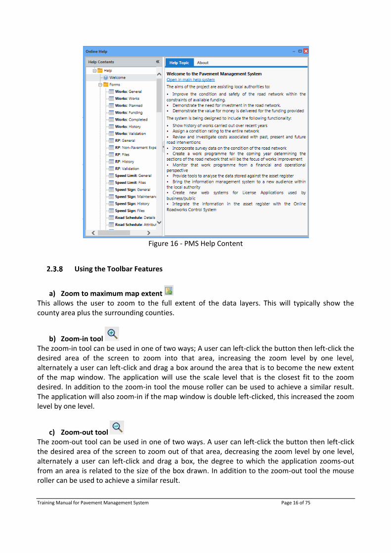
PMS Help
Within the PMS site there is a Help section which gives helpful information, including images, on
the various features and layers in the PMS system. To access this help content, click on the symbol in the bottom right of the screen beside the log in feature. Also, within each form there is a help button in the top right corner. Clicking this will open the help for this specific form.
Clicking on the symbol will open up a new window that has information on all PMS features and tools.
Training Manual for Pavement Management System Page 16 of 75
Figure 16 - PMS Help Content
Using the Toolbar Features
a) Zoom to maximum map extent This allows the user to zoom to the full extent of the data layers. This will typically show the county area plus the surrounding counties.
b) Zoom-in tool The zoom-in tool can be used in one of two ways; A user can left-click the button then left-click the desired area of the screen to zoom into that area, increasing the zoom level by one level, alternately a user can left-click and drag a box around the area that is to become the new extent of the map window. The application will use the scale level that is the closest fit to the zoom desired. In addition to the zoom-in tool the mouse roller can be used to achieve a similar result. The application will also zoom-in if the map window is double left-clicked, this increased the zoom level by one level.
c) Zoom-out tool The zoom-out tool can be used in one of two ways. A user can left-click the button then left-click the desired area of the screen to zoom out of that area, decreasing the zoom level by one level, alternately a user can left-click and drag a box, the degree to which the application zooms-out from an area is related to the size of the box drawn. In addition to the zoom-out tool the mouse roller can be used to achieve a similar result.

Training Manual for Pavement Management System Page 17 of 75
d) The pan tool By selecting the pan map tool the user can drag the map around the pane by holding the left click and moving the mouse in a direction.
e) The change view tools It is possible to return to the previous extent using the back and forward icons, this works in the same way as the tools within an internet browser.
f) Go to coordinates tool The Go to coordinate tool is useful for navigating to an area when the ITM coordinates of the area are known. When clicked, the tool prompts the user with a window to enter the ITM X Coord and Y Coord of the location desired and click Go To. This will add a marker to the map and pan to the location of this marker. By default, the X, Y values of the centre of the current map view are shown. By clicking on the red kite symbol the icon is dismissed.
Figure 17 - Go to Coordinates window
g) Area measure tool The area measure tool allows a user to measure an area by drawing the area through a series of clicks on the map. Once drawn, the user can left-click on the map window to add points to an area to amend the shape. The size will update dynamically and be visible in Measure Tool window. Double clicking will complete the shape.
Figure 18 - Area Measure Tool window
h) Line measure tool The line measure tool allows a user to measure a straight-line distance on the map through a series of clicks. The distance will update as the user clicks and be visible in Measure Tool window. Double clicking will complete the line.
Figure 19 - Line Measure Tool window

Training Manual for Pavement Management System Page 18 of 75
i) Information Tool The Info Tool retrieves information relating to a selected road segment. To use, click on the information tool in the toolbar ribbon, then click on the desired road segment. A blue bounding box will appear over the full segment of the identified road segment. A Road Information window will also appear on the right side of the screen with information relating to the identified road segment.
Figure 20 - Road Information panel
Information is provided under 4 tabs:
Works - shows all the works for the identified segment
Speed - shows all the Speed Limits for the identified segment
Surface - shows all the Surface Surveys for the identified segment
Charts - shows a chart for all PSCI surveys for the identified segment
As well as finding information about the road segment, a user can edit the Road’s data directly by clicking on “View Details”. This will open up the Road Segment form where the details of the road can be edited. See Road Segments Tool for further information.
j) Homepage Clicking on this will open the PMS Homepage in a new tab.

Training Manual for Pavement Management System Page 19 of 75
k) Toolbars The Toolbars is a way for a user to only show certain tools that he/she want to be visible. Clicking on this will open a dropdown menu where tools can be hidden from view. This will be stored in cache in your browser so will always be hidden unless the browser cache is delete.
Figure 21 - Toolbar tools being hidden
2.4 Works
A Works Job is a collection of road segments where a specific road maintenance procedure is carried out by the Council under a specific road maintenance grant.
View Works Job
Works can be viewed by turning on/off Works layers in the ‘Map Layers’ panel. The ‘Legend’ will explain the symbology to the user.
Figure 22 - Works map layer coverage
Training Manual for Pavement Management System Page 20 of 75
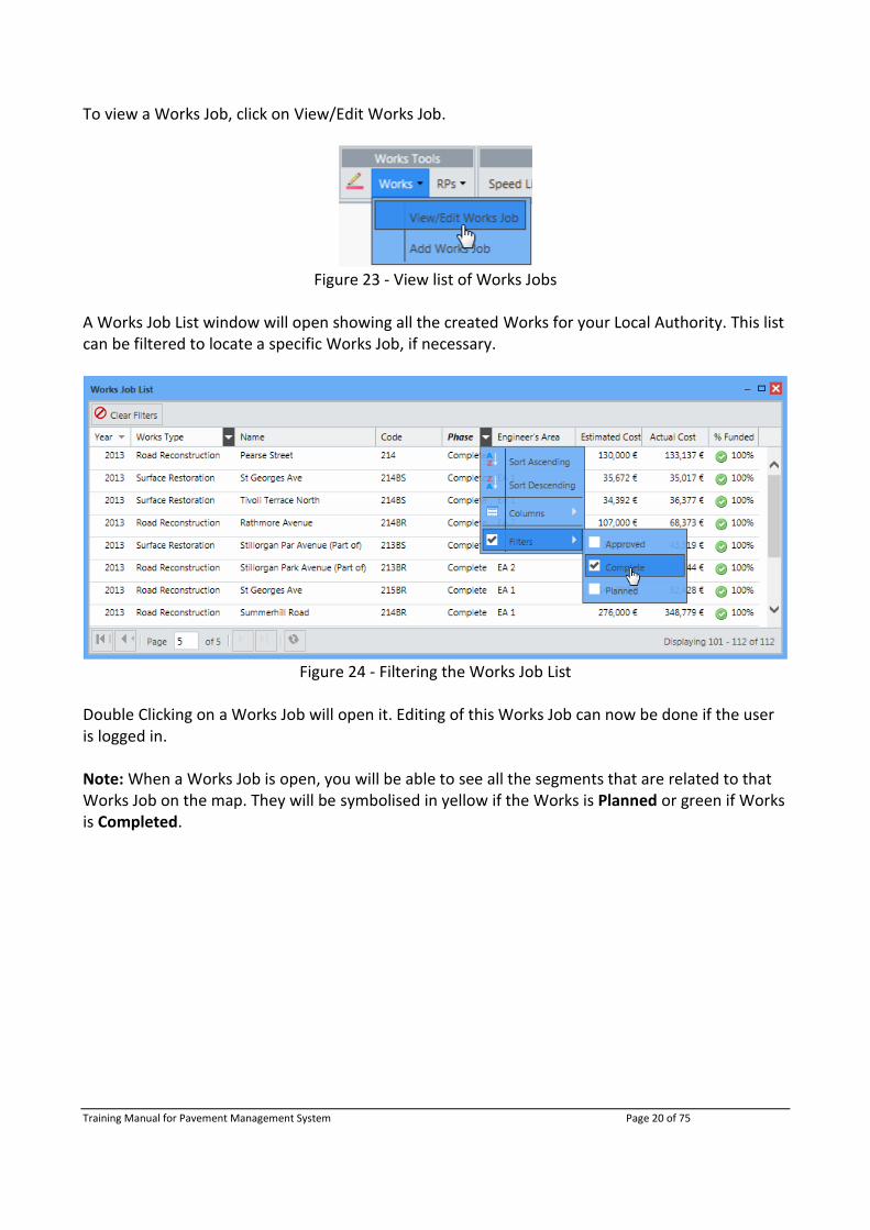
To view a Works Job, click on View/Edit Works Job.
Figure 23 - View list of Works Jobs
A Works Job List window will open showing all the created Works for your Local Authority. This list can be filtered to locate a specific Works Job, if necessary.
Figure 24 - Filtering the Works Job List
Double Clicking on a Works Job will open it. Editing of this Works Job can now be done if the user is logged in. Note: When a Works Job is open, you will be able to see all the segments that are related to that Works Job on the map. They will be symbolised in yellow if the Works is Planned or green if Works is Completed.

Training Manual for Pavement Management System Page 21 of 75
Figure 25 - Planned and Completed Works visible in yellow/green when works opened
Clicking on a segment will highlight that segment in purple.
Figure 26 - Works Job opened showing clicked segment in purple and unclicked in yellow haze.
Works Jobs can be edited through this window. New routes can be added, old routes can be shortened/removed and Works information can be also be edited. Clicking ‘Update Works’ will update the Works Job to what was changed. In the History tab, a new entry will be added after ‘Update Works’ is clicked.

Training Manual for Pavement Management System Page 22 of 75
Figure 27 - Works History
Create Works Job
To add works the user must first and select Add Works from the Works toolbar.
Figure 28 - Works Toolbar
The Works Editing Tool is used to add segments to a Works Job. The tool is only activated after opening the Add Works window or when editing a Works Job form. It is easy to use by simply clicking on the desired start and end of road segment/segments. To ensure you are on a valid road turn on Road Schedule in the map layers.
a) Works Job Form There are 7 Tabs within the Works Job form:
i. General Tab The General tab contains general details and locational information about the Works Job. There are mandatory fields that must be complete before the Works Job can be created, these are marked with an asterisk (*). Note: The name of the Works Job should be clear to distinguish it from other similar Works Jobs.

Training Manual for Pavement Management System Page 23 of 75
Figure 29 - General tab in Works Job window
ii. Works Tab The Works tab consists of fields relating to the materials that will be/were used in the Works Job as well as containing a text description field for additional information about the Works Job.
Figure 30 - Works tab in Works Job window

Training Manual for Pavement Management System Page 24 of 75
iii. Planned Tab The Planned tab contains segment information for Planned Works. The Planned Works Job segments can be viewed in Group Mode. This is used to visualise segments in terms of the groups they were digitised in when creating a multi-segment works.
Figure 31 - Planned tab in Work Job window
iv. Funding Tab The Funding tab consists of pricing information about the Works Job. This is in relation to the estimated cost of the Works before its completion and the actual cost of the Works after completion. For more information on the background for Funding click here.
Figure 32 - Funding tab in Work Job window
Training Manual for Pavement Management System Page 25 of 75
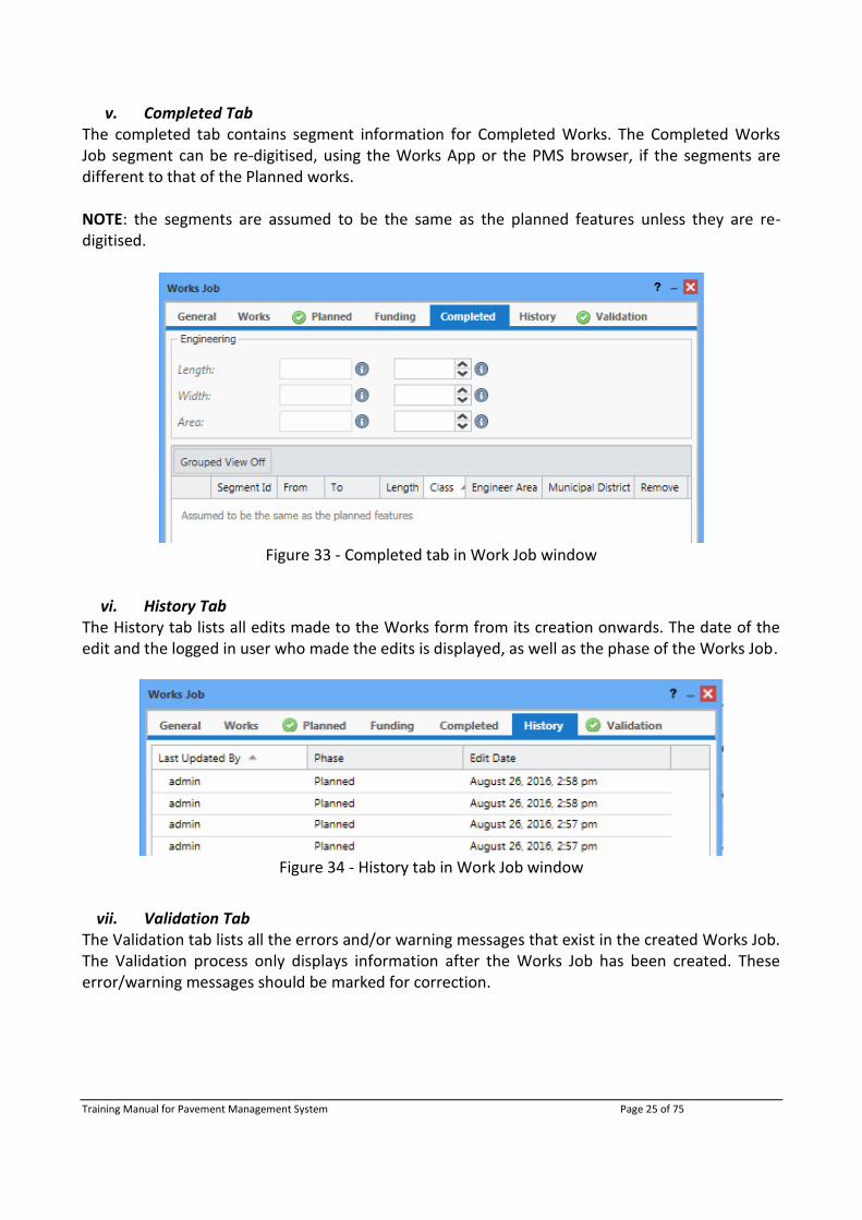
v. Completed Tab The completed tab contains segment information for Completed Works. The Completed Works Job segment can be re-digitised, using the Works App or the PMS browser, if the segments are different to that of the Planned works. NOTE: the segments are assumed to be the same as the planned features unless they are re-digitised.
Figure 33 - Completed tab in Work Job window
vi. History Tab The History tab lists all edits made to the Works form from its creation onwards. The date of the edit and the logged in user who made the edits is displayed, as well as the phase of the Works Job.
Figure 34 - History tab in Work Job window
vii. Validation Tab The Validation tab lists all the errors and/or warning messages that exist in the created Works Job. The Validation process only displays information after the Works Job has been created. These error/warning messages should be marked for correction.

Training Manual for Pavement Management System Page 26 of 75
Figure 35 - Validation tab in Work Job window
b) Adding Segments to Works Job
After the information has been added, select the Works Tool and minimise the Works Job Form to add road segments to your Works.
Figure 36 - Works Tool
The user clicks the start of the works (figure 37) on the road schedule, the user then clicks again to denote the end of the works on the road schedule. The application will use a shortest path method to resolve a route from the point A to point B, figure 38. In cases where a Work job is to be routed along a longer path that is not the shortest it will be required to add a waypoint along the route. Each point used to shape the route of the works will be denoted by an orange marker with a yellow halo, see figures 37-39.
Figure 37 - Works Tool Figure 38 - Shortest Path A to B

Training Manual for Pavement Management System Page 27 of 75
Figure 39 - A to B route not using the shortest path, by using waypoints.
Click ‘Create Works’ to complete and close out of the Works Job window.
c) Remove Segment from Works Job In order to remove a segment from the Works job list a user can use the delete button associated to each segment, in the Works Job window.
Figure 40 - Remove Segment from Works Job
Create Multi-Segment Works Job
A new feature is the ability of creating a multi-line feature. This can be done by right clicking on the map and selecting ‘Start new Group’. If you wish to add road segments to a previous group, you can right click and select ‘Active Group’ and choose the group you wish to edit.
Figure 41 - Multi-Segment Works overview
Training Manual for Pavement Management System Page 28 of 75
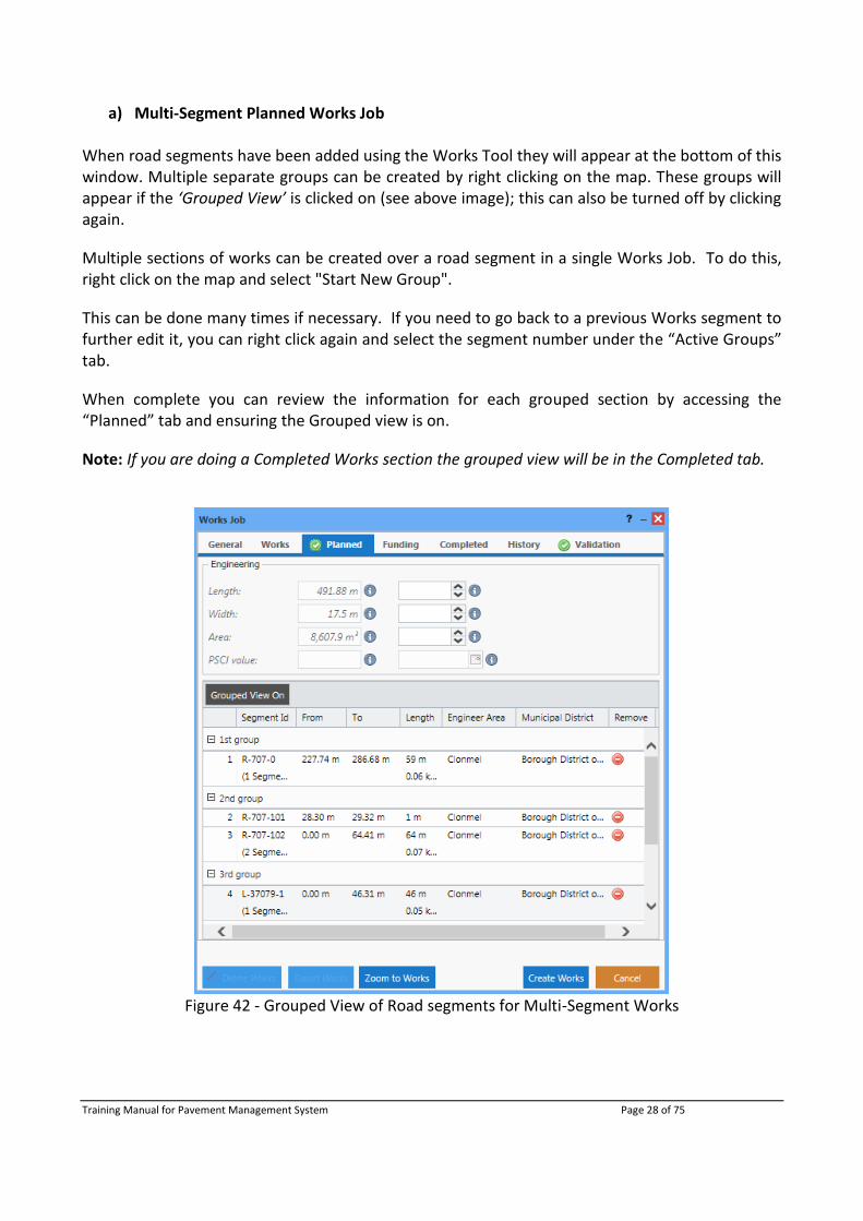
a) Multi-Segment Planned Works Job When road segments have been added using the Works Tool they will appear at the bottom of this window. Multiple separate groups can be created by right clicking on the map. These groups will appear if the ‘Grouped View’ is clicked on (see above image); this can also be turned off by clicking again.
Multiple sections of works can be created over a road segment in a single Works Job. To do this, right click on the map and select "Start New Group".
This can be done many times if necessary. If you need to go back to a previous Works segment to further edit it, you can right click again and select the segment number under the “Active Groups” tab.
When complete you can review the information for each grouped section by accessing the “Planned” tab and ensuring the Grouped view is on.
Note: If you are doing a Completed Works section the grouped view will be in the Completed tab.
Figure 42 - Grouped View of Road segments for Multi-Segment Works

Training Manual for Pavement Management System Page 29 of 75
b) Multi-Segment Completed Works Job The completed Works road segments are assumed to be the same as that of the planned features. If the completed Works are different then new Road Segments can be added using the Works Tool. These road segments will appear in green instead of yellow.
In order to change a Works Job to Complete, a user must change the Works Phase to Complete under the General tab, as below.
Figure 43 - Changing “Planned” Works to “Completed”
Editing the “Completed” Work Job segments is done the same way as creating a Works segment, using the Works Tool. You will notice that the “Completed” edits appear in Green.
Figure 44 - Creating a Completed Works Job route over the original Planned route
When edits are finished click Update Works. Opening up a Completed Works will show the Planned works in a yellow haze under the Completed works as a reference.

Training Manual for Pavement Management System Page 30 of 75
Figure 45 - Completed (green) and Planned (yellow) routes shown when a Completed Works form
is opened
A new App called the Works Type App will be used to record the actual completed Works and this will be automatically uploaded to the PMS system.
Export Works Job
Exporting a Works Job is quick and easy. It is done by clicking Export Works and it creates a report of the Works Job in excel format.
Figure 46 - Export Work functionality
Delete Works Job
If you are sure you wish to delete the Works Job click Delete Works. NOTE: A Works Job can only be deleted if it is not in a Roads Programme. It must first be removed from an RP before deleting it.
Figure 47 - Delete Works Job functionality
A warning message will pop up to prevent any mistaken deletions.

Training Manual for Pavement Management System Page 31 of 75
Figure 48 - Delete Works job warning message
N.B. Once Yes is clicked the Works Job is deleted from the system and so cannot be brought back.
2.5 Roads Programme
A Roads Programme is a collection of Works carried out by the Council under a specific road maintenance grant.
View Roads Programme
Roads Programmes (RPs) can be viewed by turning on RPs layers in the ‘Map Layers’ panel. The ‘Legend’ will explain the symbology to the user.
Figure 49 - Roads Programme map layers

Training Manual for Pavement Management System Page 32 of 75
To view and edit/delete a previously created RP a user can click on View/Edit Roads Programme under the RPs dropdown menu.
Figure 50 - Road Programmes Tool
This will open the Roads Programmes List window containing a list of all the RPs for your Local Authority. Double clicking on an entry will open the RPs window with the information and related works. Note: RPs List fields are filterable to allow for specific RPs to be searched easily. Also, columns can also be hidden/shown to view only the required fields
Figure 51 - Road Programmes List
Double clicking a RP on the list will prompt the user with a dialog box with all information associated with the particular RP. The ‘Zoom to RP’ button will focus the map window on the RP. Clicking the ‘Cancel’ button will close the RP window.
Create Roads Programme
RPs are added via the ‘Add New Road Programme’ option on the ‘RPs’ drop-down menu available on the toolbar.

Training Manual for Pavement Management System Page 33 of 75
Figure 52 - Add New Road Programme
A new blank RP window will be presented to the user. The user should fill in all fields relevant to the task for which the RP is being collected; a description while not mandatory is encouraged as this will inform anyone who is viewing the RP.
Figure 53 - Creating a new RP
A RP is made of a series of Works Jobs; the ‘Update and Set Priority’ button on the ‘Roads Programme’ window allows a user to select the Works Jobs that are to form the RP.

Training Manual for Pavement Management System Page 34 of 75
Note: Setting the Funding Category to “Discretionary Grant”, as above, will only show those works that have “Discretionary Grant” as a funding category, as below. Only those Works Jobs that have the same Funding Category as described can be added to the RP.
Figure 54 - Add Works Job to the RP
Once Works are highlighted they can be dragged across to add them to the RP. Alternatively, the arrows in the middle can be used. The right arrow adds jobs to the RP while the left arrow removes jobs from the RP. Works can be filtered by using the arrow drop down associated with the field titles on the left-hand pane. The ‘Clear Filters’ button will remove any filter applied to the works selection window.
Figure 55 - Filtering Works Jobs to add to RP
It is possible to alter the priority of works by dragging them up or down the right-hand pane of the ‘Select Works’ window as required.

Training Manual for Pavement Management System Page 35 of 75
Clicking ‘Save’ on the window will return the user to the ‘Roads Programme’ window where the Works will be updated and the Estimated Cost generated. When the RP is complete, click Create RP to create the Roads Programme.
Figure 56 - Works Added and Create RP
After clicking Create RP, the Create RP button will change to ‘Update RP’. Changes and updates can be made to Roads Programme by clicking this. Click Cancel after creation/updates are complete to exit the window and finish creating/updating the Roads Programme.
Submit Roads Programme to DTTAS
To submit a Roads Programme to the Department of Transport, Tourism and Sport (DTTAS), open the Roads Programme and click ‘Submit’ in the centre of the RP Window.

Training Manual for Pavement Management System Page 36 of 75
Figure 57 - Submission of RP to DTTAS
A confirmation submission pop-up will appear, click yes to submit the Roads Programme. Once submitted, the user who submitted the RP and the date submitted will be added the RP form to inform other users that this RP was already submitted to DTTAS.
Figure 58 - RP Submitted to DTTAS
Delete Roads Programme
To delete an RP, select the ‘Delete RP’ button in the Roads Programme window.
Figure 59 - Delete RP
The user will be prompted to confirm the decision and a verification dialogue will appear when the RP has been successfully deleted.
Figure 60 - Delete RP warning message
Export Roads Programme
A user has the ability to export of a RP from the PMS system by selecting the ‘Export RP’ button in the Roads Programme window.
Figure 61 - Export RP

Training Manual for Pavement Management System Page 37 of 75
This will present the user with an excel document which contains particulars of the RP including general and before and after details about each Works Job.
2.6 Speed Limits
There are two components to the PMS system for capturing speed limit information; speed limit signs and speed limits along the road network. An Android APP has been developed to assist with capturing the signpost locations and the latter is entered through the PMS browser.
Figure 62 - Speed Limits map layers
Speed Signs
While the Speed Limit Signs App is the primary method of recording speed signs, the PMS Browser can also be used for entering location as well as for repositioning and removing information.
a) View Speed Sign Data In the Map Layers, if a user opens the Speed Sign folder they will be presented with a list of different types of speed limits which can be visualised on the map. The Legend section illustrates the symbology for the various speed limits.
To view and edit/delete a previously created speed limit sign a user can do one of the following:
1. Hover over a Speed Sign, this will activate a tooltip information window for that sign. To view and edit/delete the speed sign click on the speed sign. The Speed Limit Sign window containing sign information and any images will open.
Note: The Info Tool is not required to identify speed signs
Figure 63 - Speed Limits Sign tool tip
Training Manual for Pavement Management System Page 38 of 75
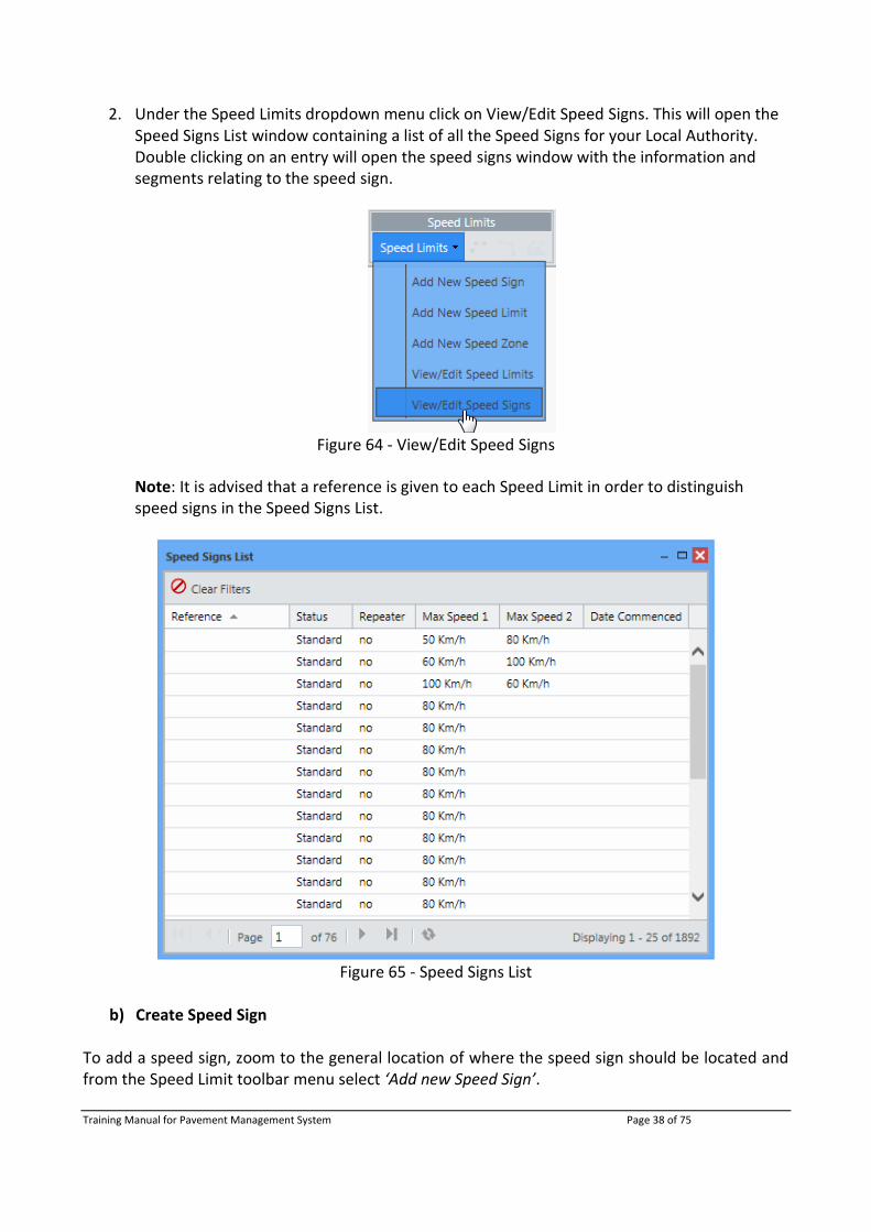
2. Under the Speed Limits dropdown menu click on View/Edit Speed Signs. This will open the Speed Signs List window containing a list of all the Speed Signs for your Local Authority. Double clicking on an entry will open the speed signs window with the information and segments relating to the speed sign.
Figure 64 - View/Edit Speed Signs
Note: It is advised that a reference is given to each Speed Limit in order to distinguish speed signs in the Speed Signs List.
Figure 65 - Speed Signs List
b) Create Speed Sign
To add a speed sign, zoom to the general location of where the speed sign should be located and from the Speed Limit toolbar menu select ‘Add new Speed Sign’.

Training Manual for Pavement Management System Page 39 of 75
Figure 66 - Add New Speed Sign
This will open the Speed Sign window, where relevant information should be entered.
Figure 67 - Enter Speed Sign Information
After the information has been added select the Speed Sign Tool to add the location of the Speed Sign to the map.
Figure 68 - Speed Sign Tool
Locate the sign on the map as accurately as possible, zooming in as needed. You should place the sign where it is on the ground, as seen in the image below, and not on the road centreline.

Training Manual for Pavement Management System Page 40 of 75
Figure 69 - Speed Sign location on map
Click the ‘Create Sign’ button on the data entry form to create the Speed Sign. Click cancel to close the Speed Sign window. You may notice that the orange point where your speed sign was located is now gone. To view the Speed Sign you have added turn on Speed Signs in the Map Layers.
c) Edit Speed Sign To relocate a speed sign, click on the desired Speed Sign to be moved to open the Speed Sign
window. Then click the Speed Sign Tool, and either drag or select the new location for the sign to be located by clicking on the map. The orange point will be moved to this new location. When you are happy with the edits press the ‘Update Sign’ button on the form and the location of Speed Sign will be updated.
d) Delete Speed Sign To delete a Speed Sign, the user must first open the Speed Sign window as above and click on the ‘Delete Sign’ button.
Figure 70 - Delete Speed Sign
Once the ‘Delete Sign’ is clicked, a confirmation pop-up will appear. Click ‘Yes’ to confirm the
deletion of the Speed Sign.
Training Manual for Pavement Management System Page 41 of 75
Speed Limits
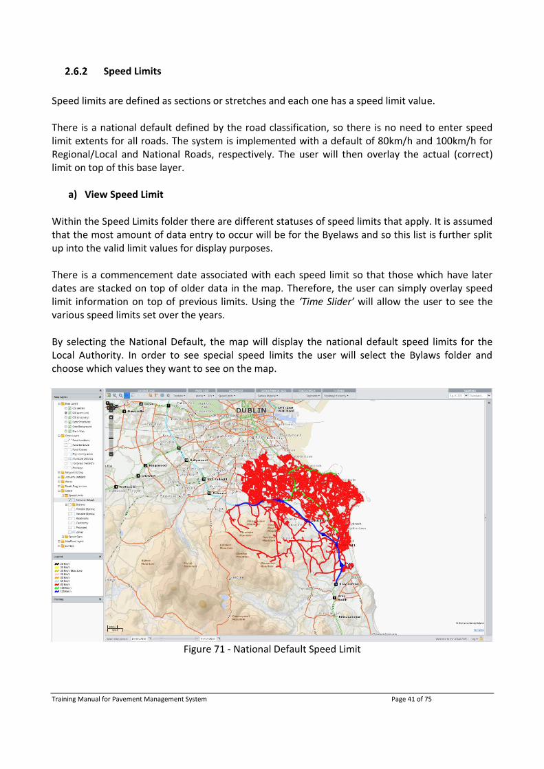
Speed limits are defined as sections or stretches and each one has a speed limit value. There is a national default defined by the road classification, so there is no need to enter speed limit extents for all roads. The system is implemented with a default of 80km/h and 100km/h for Regional/Local and National Roads, respectively. The user will then overlay the actual (correct) limit on top of this base layer.
a) View Speed Limit Within the Speed Limits folder there are different statuses of speed limits that apply. It is assumed that the most amount of data entry to occur will be for the Byelaws and so this list is further split up into the valid limit values for display purposes. There is a commencement date associated with each speed limit so that those which have later dates are stacked on top of older data in the map. Therefore, the user can simply overlay speed limit information on top of previous limits. Using the ‘Time Slider’ will allow the user to see the various speed limits set over the years. By selecting the National Default, the map will display the national default speed limits for the Local Authority. In order to see special speed limits the user will select the Bylaws folder and choose which values they want to see on the map.
Figure 71 - National Default Speed Limit

Training Manual for Pavement Management System Page 42 of 75
b) Create Speed Limit To add a Speed Limit, turn on the Road Schedule layer for context and zoom to the general location where the Speed Limit will be applied to. From the menu bar select ‘Add new Speed Limit’
Figure 72 - Add New Speed Limit
On the Speed Limit form, enter the relevant information.
Figure 73 - Speed Limit form
Select the Speed Limit Polyline tool from the toolbar
Figure 74 - Speed Limit Polyline tool
Training Manual for Pavement Management System Page 43 of 75
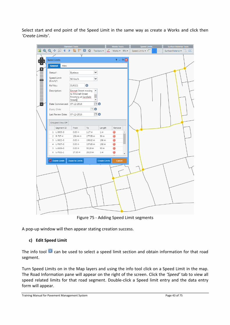
Select start and end point of the Speed Limit in the same way as create a Works and click then ‘Create Limits’.
Figure 75 - Adding Speed Limit segments
A pop-up window will then appear stating creation success.
c) Edit Speed Limit
The info tool can be used to select a speed limit section and obtain information for that road segment. Turn Speed Limits on in the Map layers and using the info tool click on a Speed Limit in the map. The Road Information pane will appear on the right of the screen. Click the ‘Speed’ tab to view all speed related limits for that road segment. Double-click a Speed limit entry and the data entry form will appear.
Training Manual for Pavement Management System Page 44 of 75
Edits can then be made to the survey information and segments can be added/removed. The user can manually change the ‘From’/ ‘To’ measurements as seen below.
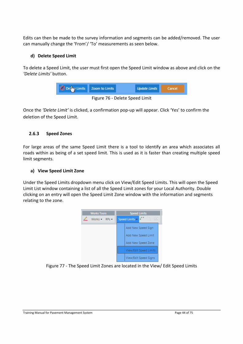
d) Delete Speed Limit To delete a Speed Limit, the user must first open the Speed Limit window as above and click on the ‘Delete Limits’ button.
Figure 76 - Delete Speed Limit
Once the ‘Delete Limit’ is clicked, a confirmation pop-up will appear. Click ‘Yes’ to confirm the
deletion of the Speed Limit.
Speed Zones
For large areas of the same Speed Limit there is a tool to identify an area which associates all roads within as being of a set speed limit. This is used as it is faster than creating multiple speed limit segments.
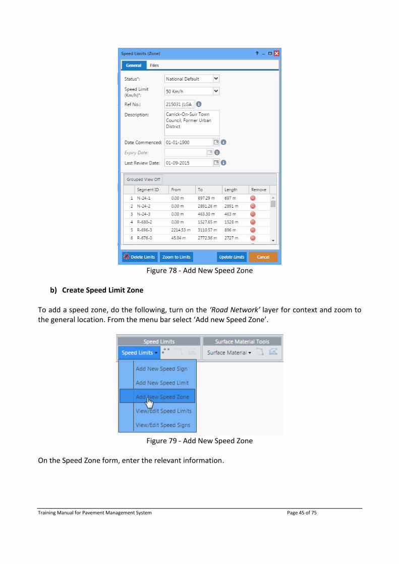
a) View Speed Limit Zone
Under the Speed Limits dropdown menu click on View/Edit Speed Limits. This will open the Speed Limit List window containing a list of all the Speed Limit zones for your Local Authority. Double clicking on an entry will open the Speed Limit Zone window with the information and segments relating to the zone.
Figure 77 - The Speed Limit Zones are located in the View/ Edit Speed Limits
Training Manual for Pavement Management System Page 45 of 75
Figure 78 - Add New Speed Zone
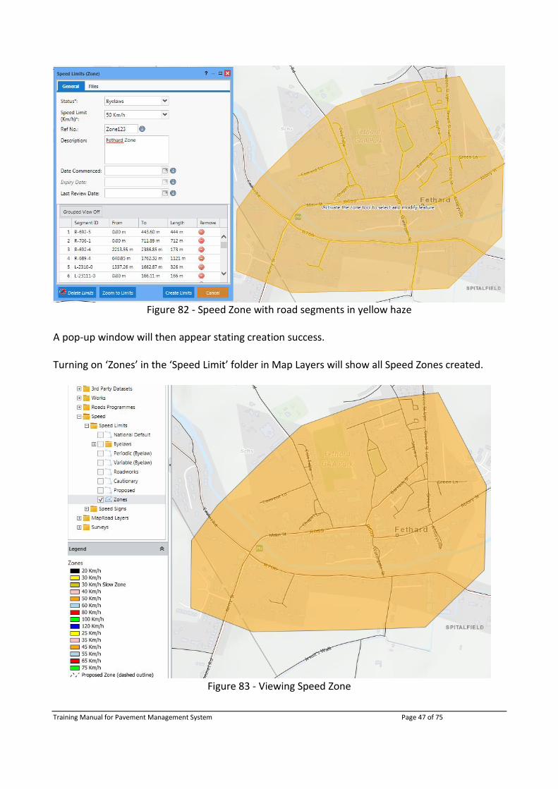
b) Create Speed Limit Zone
To add a speed zone, do the following, turn on the ‘Road Network’ layer for context and zoom to the general location. From the menu bar select ‘Add new Speed Zone’.
Figure 79 - Add New Speed Zone
On the Speed Zone form, enter the relevant information.

Training Manual for Pavement Management System Page 46 of 75
Figure 80 - Speed Limit form
Select the Speed Limit Zone tool from the toolbar
Figure 81 - Speed Limit Zone tool
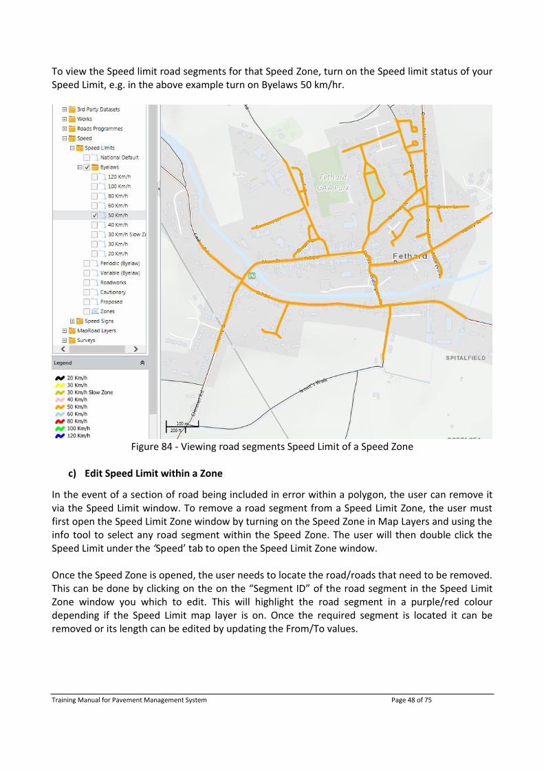
Create a polygon around the area of interest by clicking to create vertexes and double clicking to finish. All road segments in the Speed Zone will appear as yellow haze. Click ‘Create Limits’ to complete the speed zone. All Road Segments within that Speed Zone will now have been assigned a Speed Limit of that Speed Zone.
Training Manual for Pavement Management System Page 47 of 75
Figure 82 - Speed Zone with road segments in yellow haze
A pop-up window will then appear stating creation success. Turning on ‘Zones’ in the ‘Speed Limit’ folder in Map Layers will show all Speed Zones created.
Figure 83 - Viewing Speed Zone
Training Manual for Pavement Management System Page 48 of 75
To view the Speed limit road segments for that Speed Zone, turn on the Speed limit status of your Speed Limit, e.g. in the above example turn on Byelaws 50 km/hr.
Figure 84 - Viewing road segments Speed Limit of a Speed Zone
c) Edit Speed Limit within a Zone
In the event of a section of road being included in error within a polygon, the user can remove it via the Speed Limit window. To remove a road segment from a Speed Limit Zone, the user must first open the Speed Limit Zone window by turning on the Speed Zone in Map Layers and using the info tool to select any road segment within the Speed Zone. The user will then double click the Speed Limit under the ‘Speed’ tab to open the Speed Limit Zone window. Once the Speed Zone is opened, the user needs to locate the road/roads that need to be removed. This can be done by clicking on the on the “Segment ID” of the road segment in the Speed Limit Zone window you which to edit. This will highlight the road segment in a purple/red colour depending if the Speed Limit map layer is on. Once the required segment is located it can be removed or its length can be edited by updating the From/To values.

Training Manual for Pavement Management System Page 49 of 75
Figure 85 - Removing of a road segment from a Speed Limit Zone
Figure 86 - Road segment removed from Speed Limit Zone

Training Manual for Pavement Management System Page 50 of 75
d) Delete Speed Limit Zone To delete a Speed Limit Zone, the user must first open the Speed Limit Zone window by turning on the Speed Zone in Map Layers and using info tool select any road segment within the Speed Zone. Once the speed Zone is opened, click on the ‘Delete Sign’ button.
Figure 87 - Delete Speed Limit Zone
Once the ‘Delete Limit’ is clicked, a confirmation pop-up will appear. Click ‘Yes’ to confirm the
deletion of the Speed Limit Zone.
Another pop-up will appear stating that the Speed Limit Zone was successfully deleted.
2.7 Surface Materials
Create Surface Material Survey
To add a Surface Survey, turn on the ‘Road Network’ layer for context and zoom to the general location where the Surface Survey will be applied to. From the menu bar select ‘Add New Surface Survey’.
Figure 88 - Add New Surface Survey
On the Surface Survey form, enter the relevant information.
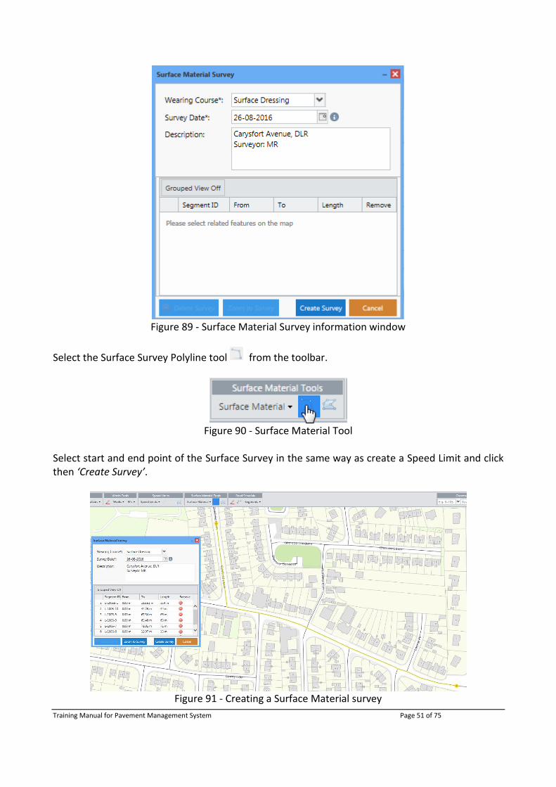
Training Manual for Pavement Management System Page 51 of 75
Figure 89 - Surface Material Survey information window
Select the Surface Survey Polyline tool from the toolbar.
Figure 90 - Surface Material Tool
Select start and end point of the Surface Survey in the same way as create a Speed Limit and click then ‘Create Survey’.
Figure 91 - Creating a Surface Material survey

Training Manual for Pavement Management System Page 52 of 75
A pop-up window will then appear stating creation success.
Edit Surface Material Survey
The info tool can be used to select a Surface Material survey and obtain information for that road segment. Turn Surface Materials on in the Map layers and using the info tool click on a Surface Material survey in the map. The Road Information pane will appear on the right of the screen. Click the ‘Surface’ tab to view all Surface Material surveys for that road segment. Double-click a Surface Material survey and the data entry form will appear. NOTE: All Surface Material data uploaded from the surface Survey App will appear in the Road Information tab but is unable to be edited or opened. They appear in a little grey text.
Figure 92 - Road Information ‘Surface’ tab
Edits can then be made to the survey and segments can be added/removed in the same manner as Speed Limits.
Delete Surface Material Survey
To delete a Surface Material Survey, the user must first open the Surface Material Survey window. Once the Surface Material Survey window is opened, click on the ‘Delete Sign’ button.
Figure 93 - Delete Surface Survey

Training Manual for Pavement Management System Page 53 of 75
Once the ‘Delete Limit’ is clicked, a confirmation pop-up will appear. Click ‘Yes’ to confirm the
deletion of the Surface Survey.
Another pop-up will appear stating that the Surface Material Survey was successfully deleted.
2.8 Road Segment Tool
With the migration from MapRoad to OSi Prime2, new layers and tools have been added to allow users manage (add, edit and delete) road segments within PMS. The following sections will discuss these processes.
The Segments tool allows users to:
Edit segment information for roads currently under the Local Authority’s control
Edit the geometry for roads currently under the Local Authority’s control
Remove registered segments from the Local Authority’s Road Schedule
Add unregistered segments to the Local Authority’s Road Schedule
NOTE: only specific users will be able to edit the Road Schedule using this new Road Segment Tool. These users will be assigned as an “Editor” role. This can be done via the Management Tool.
Viewing a Road Segment
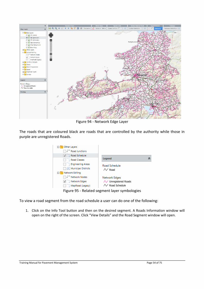
In the Map Layers under Network Editing, there is a Network Edges layer. Turn this on to display all registered (black lines) and unregistered (purple lines) road segments within the Local Authorities. To see segments that are only within the road schedule turn on Road Schedule under Other Layers.
Training Manual for Pavement Management System Page 54 of 75
Figure 94 - Network Edge Layer
The roads that are coloured black are roads that are controlled by the authority while those in purple are unregistered Roads.
Figure 95 - Related segment layer symbologies
To view a road segment from the road schedule a user can do one of the following:
1. Click on the Info Tool button and then on the desired segment. A Roads Information window will open on the right of the screen. Click “View Details” and the Road Segment window will open.

Training Manual for Pavement Management System Page 55 of 75
Figure 96 - Using the Info Tool to view Segment details
2. Open a specific Road Segment from the Segments List using View/Edit Segment from the Segments
dropdown menu.
Figure 97 - Viewing Segments
This will open the Segments List window which lists all registered road segments that the Local Authority are in charge of. A specific road segment can be easily located by filtering by a column.
Figure 98 - Filtering of the Segments List

Training Manual for Pavement Management System Page 56 of 75
Double clicking on an entry will open the Road Segment form. Here information/geometry can be edited/removed.
Figure 99 - Segment Form opened from Segments List
Adding a Road Segment
To add a segment, select Add Segment from the Segments dropdown list.
Figure 100 - Add Segment
This will open the Road Segment form window containing 4 tabs where information relating to the segment is stored.

Training Manual for Pavement Management System Page 57 of 75
Road Details - contains general details and locational information about the Road Segment.
Attributes - contains all the potential attribute information that could be related to a Road Segment.
Legacy Values - contains legacy information from MapRoad.
History - lists all edits made to the Road Segment form from its creation onwards.
Figure 101 - Blank Segments Form
When the user enters the Segment Id for a new road segment, they will only enter the Road Number (middle part) and the Segment number (3rd part). The system derives the class from what was entered based on the below table.
Road Number Digits Class Description
01-50 2 NP National Primary
51-99 2 NS National Secondary
100 - 999 3 R Regional
1000 - 4999 4 LP Local Primary
5000 - 9999 4 LS Local Secondary
10000 - 99999 5 LT Local Tertiary

Training Manual for Pavement Management System Page 58 of 75
Figure 102 - Segment Id generation
Following the addition of information to the Road Segment form, the segment’s geometry can be drawn. NOTE: geometry is not required to create a segment but if no geometry is drawn then the information added to the form is not linked to a road and so no road has been added to the Local Authority’s Road Schedule. To add geometry click on the Segments Tool in the Road Schedule toolbar.
Figure 103 - Segment Tool
Using this tool, a user can select the start and end locations of an unregistered road segment. The tool will route through each OSi PRIME2 Edge (junction to junction) and assign these Edges to become a new road segment.

Training Manual for Pavement Management System Page 59 of 75
Figure 104 - Creating Segment by digitising edges.
Click Create Segment to register this Road Segment to the Local Authority’s Road Schedule.
Segment Nodes
The “Start at…” and “Ends at…” fields come from the start/end nodes of the drawn segment. A user can edit these node descriptions by clicking on Edit after the Road Segment has been created.
Figure 105 - Segment Nodes
Similarly, these can be edited outside of the Road Segment form by using the Junction Tool.
Training Manual for Pavement Management System Page 60 of 75
Viewing Nodes
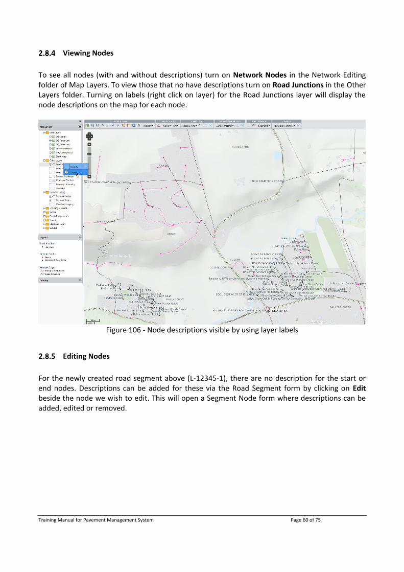
To see all nodes (with and without descriptions) turn on Network Nodes in the Network Editing folder of Map Layers. To view those that no have descriptions turn on Road Junctions in the Other Layers folder. Turning on labels (right click on layer) for the Road Junctions layer will display the node descriptions on the map for each node.
Figure 106 - Node descriptions visible by using layer labels
Editing Nodes
For the newly created road segment above (L-12345-1), there are no description for the start or end nodes. Descriptions can be added for these via the Road Segment form by clicking on Edit beside the node we wish to edit. This will open a Segment Node form where descriptions can be added, edited or removed.

Training Manual for Pavement Management System Page 61 of 75
Figure 107 - Adding Node description within Segments form
After clicking Update Node, the description is saved and added to the Road Segments form, the label and symbology for this node have also been updated (the colour of the Node goes from pink (no description) to black (contains description)).
Figure 108 - Node description added
To edit node descriptions outside of the Road Segment form, the Road Junction tool can be used.
Delete a Road Segment
To delete a Road Segment, click Delete Segment. This will remove the road information and unregister the edges previously assigned to this road segment. NOTE: This function will NOT delete the underlying geometry, it will only remove the attributes assigned to the geometry. The data (Works, PSCI, Speeds, etc.) captured on the deleted road segment will NOT be delete either, so there is no loss of data.
Figure 109 - Delete Segment

Training Manual for Pavement Management System Page 62 of 75
2.9 Road Junction Tool
The Junction Tool allows user to add, edit or delete node descriptions outside of the Road Segment form.
Figure 110 - Junction Tool
When this tool is activated and the Network Nodes layer is turned on, clicking on a pink node will allow a user to add a description to the node while clicking on a black node will allow a user to edit or remove the description from the node.
Figure 111 - Editing a description using the Junction Tool

Training Manual for Pavement Management System Page 63 of 75
3 Management Tool
The PMS Management Tool is an administrative tool used to control:
PMS Users
Works Unit Costs
Import PSCI Surveys
View PSCI Surveys
View Surface Material Surveys
The Management Tool has different views/functionality depending if the logged in user is an administrative or not. Non-admin users will only be able to:
Import PSCI Surveys
View PSCI Surveys
View Surface Material Surveys
To access the PMS Management Tool system, click on the Management Tool image on the PMS Home Page or enter the PMS Management Tool URL for your Local Authority in to the browser, https://Thenameofyourlocalauthroity.maproadpms.ie/ManagementTool e.g. https://dunlaoghaire.maproadpms.ie/ManagementTool.
Figure 112 - PMS Management Tool
NOTE: In the below figures, usernames, passwords, Local Authority details, etc. have been blurred out.
Training Manual for Pavement Management System Page 64 of 75
3.1 Admin User Functionalities
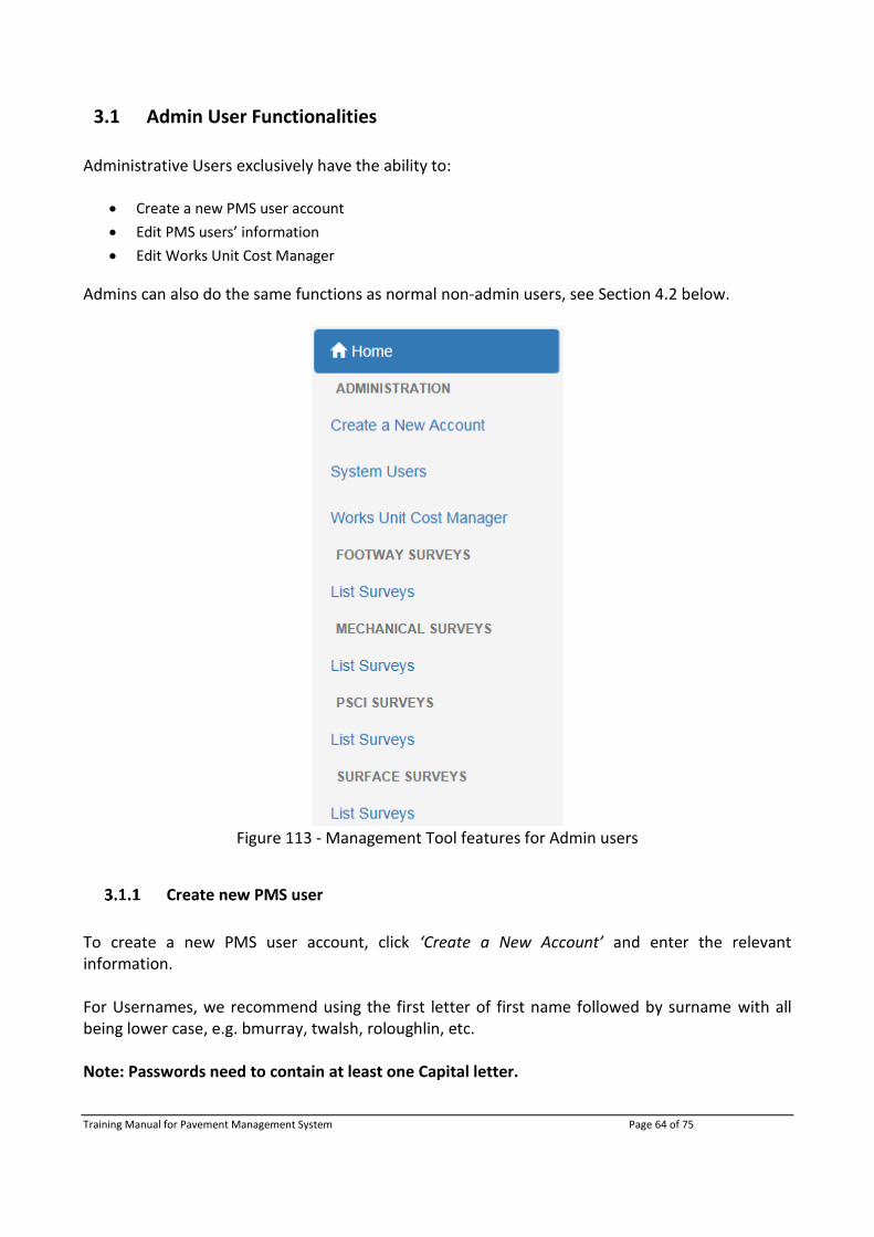
Administrative Users exclusively have the ability to:
Create a new PMS user account
Edit PMS users’ information
Edit Works Unit Cost Manager
Admins can also do the same functions as normal non-admin users, see Section 4.2 below.
Figure 113 - Management Tool features for Admin users
Create new PMS user
To create a new PMS user account, click ‘Create a New Account’ and enter the relevant information. For Usernames, we recommend using the first letter of first name followed by surname with all being lower case, e.g. bmurray, twalsh, roloughlin, etc. Note: Passwords need to contain at least one Capital letter.

Training Manual for Pavement Management System Page 65 of 75
User Roles can be either:
Administrator - full access
Editor - can create/edit/delete all data including Road Schedule editing
Read-Write - can create/edit/delete all data NOT including Road Schedule editing
Read-Only - can only view data
Figure 114 - Create New PMS User
System Users
Admin users have the ability to view and edit PMS system user information.
Figure 115 - System Users

Training Manual for Pavement Management System Page 66 of 75
a) Reset Password
If a user needs to reset his/her, the admin can do this by clicking the key symbol beside that user. This opens a new window where a new Password will be created. An email will be automatically sent to the user whose password was changed containing the new password.
Figure 116 - Reset User Password
b) Edit User information
To edit user details such as Username, email address or user role, the admin can select the pen
symbol beside that user. A new window will appear where user details can be edited. Also, the admin can unlock/lock a user from PMS site. If the user has entered his/her password incorrectly into PMS 5 times, that user will be locked out of PMS. To unlock that user, click on the
pen beside that user and then uncheck the box and click ‘Save Changes’.
Figure 117 - Unlock user from PMS
After the changes have been saved you will be brought back to the System Users page where a confirmation of the change will be shown at the top of the screen.

Training Manual for Pavement Management System Page 67 of 75
c) Delete User
To delete a PMS user from the system, click on the symbol beside the desired user. This will pop-up a confirmation deletion window.
Figure 118 - Delete PMS user
Clicking yes will delete the user and bring you back to the System User page where a confirmation of deletion will be shown at the top of the screen, similar to Figure 98 above.
Works Unit Cost Manager
The Unit Costs for each Works Type in each Engineering Area can be edited.
Figure 119 - Works Unit Cost Manager
Editing a unit Cost is easily done by clicking on the pen symbol beside the desired Engineering Area. The user does not need to click directly on the specific Works Type as all Works Types for the selected Engineering Area can be edited from the one page as seen below.
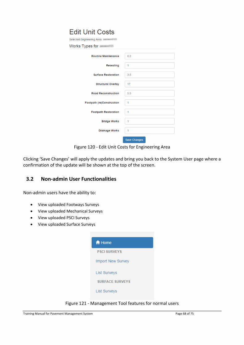
Training Manual for Pavement Management System Page 68 of 75
Figure 120 - Edit Unit Costs for Engineering Area
Clicking ‘Save Changes’ will apply the updates and bring you back to the System User page where a confirmation of the update will be shown at the top of the screen.
3.2 Non-admin User Functionalities
Non-admin users have the ability to:
View uploaded Footways Surveys
View uploaded Mechanical Surveys
View uploaded PSCI Surveys
View uploaded Surface Surveys
Figure 121 - Management Tool features for normal users

Training Manual for Pavement Management System Page 69 of 75
View Surveys
All surveys uploaded to PMS can be viewed in the same manner. The below process using PSCI surveys as an example. All uploaded PSCI surveys from the MapRoadMobile Application can be viewed, edited and deleted, depending if the user has the suitable role for these functions (i.e. Admins and Read-Write users can view, edit and delete. Read-Only users can only view PSCI Surveys).
Figure 122 - View uploaded PSCI Surveys
a) Edit PSCI Survey
To edit details of an uploaded PSCI Survey such as the description, Surveyor name and/or if it
was/was not a Test Loop by selecting the pen symbol beside that user. A new window will appear where PSCI Survey details can be edited. The file name cannot be edited.
Figure 123 - Update PSCI Survey details

Training Manual for Pavement Management System Page 70 of 75
Click Save Changes to apply your edits and you will be brought back to PSCI Survey page with a confirmation of changes on the top of the screen, as seen below.
b) Delete PSCI Survey
To delete a PSCI survey from the system click on the symbol beside the desired user. This will pop-up a confirmation deletion window.
Figure 124 - Delete PSCI survey
Clicking ‘Yes’ will delete the PSCI survey and bring you back to the PSCI Survey page where a confirmation of deletion will be shown at the top of the screen.

Training Manual for Pavement Management System Page 71 of 75
4 Support & Information Portal
Due to increasing support issues on the various MapRoad PMS applications across all local authorities, a support website was created that contains documentation and help videos on all MapRoad PMS applications. The MapRoad PMS Support and Information Portal should be the primary go to website for informative documentation/videos relating to all aspects of the MapRoad PMS suite of browser and tablet based applications. To access the support content, go to http://www.maproadpms.ie.
Figure 125 - MapRoad PMS Support & Information Portal
From here you will able to navigate to the various aspects of the MapRoad PMS applications.

Training Manual for Pavement Management System Page 72 of 75
Tutorial documentation and videos are constantly being created/updated and uploaded to the support website. Please access and review the content of this site before adding a technical support/query to the PMS Ticket Tracker system.
4.1 MapRoad PMS Applications
For each of the below MapRoad PMS applications there are helpful step by step tutorial documents and informative videos:
MapRoad PMS - Desktop Applications
MapRoad PMS - Pavement Management System
MapRoad PMS - Mobile Applications
MapRoad PMS - Ticket Tracker
MapRoad PMS - Desktop Applications
MapRoad is a suite of software products used by Local Authorities to manage road data such as the road itself, road maintenance data, accident data, bridge data, traffic data and claim data. MapRoad has a range of Pavement Management tools for Road Authorities in Ireland, and is supported by the Department of Transport. Additional broad range of tools will be provided in new versions to build Pavement Management Capabilities and Techniques nationally. MapRoad modules include:
Road Network This is the core Module managing data associated with the road itself; its geographical location, its name, width, length, date taken in charge.
Road Management & Road Management Plus These modules have been superseded by the intranet based Pavement Management System (PMS) web application.
Road Accident This module manages data associated with accidents such as their location and all data from CT68/Garda Accident Report Form. The module allows automatic import of NRA data, produces low cost proposal forms and facilitates accident analysis.
Road Bridge This module manages data associated with bridges such as inspection data, inventory data and works carried out, including import of NRA Bridge Inventory Data.

Training Manual for Pavement Management System Page 73 of 75
Road Hazard This module manages data associated with claims made to Local Authorities. Allowing inspections and works carried out to be recorded and reports and acknowledgment letters to be created.
MapRoad PMS - Pavement Management System
The PMS web solution is open source, with proprietary elements, and allows assessments including routing, feature editing and attribution, with time period based visualisation. The overall solution allows effective planning of road management and work tasks at both local authority and national level. An online ticketing system and information portal website are available to all users of the system. MapRoad PMS is an example of technology allowing more to be done with less, freeing up the user to optimise their working day, and allowing decision makers quicker access to data in a readily accessible format.
MapRoad PMS - Mobile Applications
All MapRoad PMS Mobile applications are available for Android platforms, and can operate without direct network connection. Once Android devices are connected to the internet via Mobile Data or Wi-Fi, data captured off-line can be uploaded to centralised data management systems.
Works A tablet application for recording Planned and Completed Works’ Jobs; Local Authority Works’ job can be synchronised with the tablet application and made available for offline editing.
MapRoad Mobile
An Android based application for the rapid capture of Pavement Survey Condition Index (PSCI) and Surface Material data. Latest available Road Schedule now available to download directly within the application.
Speed Limits An Android based application for capturing speed limit sign data, including location and photographs.
MapRoad PMS - Ticket Tracker
The MapRoad PMS Ticket Tracker system is used to log details about an issue and request technical support. The Ticket Tracker System is accessible via http://support.maproadpms.ie

Training Manual for Pavement Management System Page 74 of 75
Please log any future queries you may have to the MapRoad PMS Ticket Tracker, with as much detail as you can (including screenshots or additional file data where appropriate), and we will respond as soon as possible. Non-service affecting tickets will be resolved with decreasing priority, we will however address all ticket tracker submissions within an acceptable time frame from the initial log date.
4.2 Help Documents
To view all help documents for the various MapRoad PMS applications simply click on the ‘Help Documents’ tab, as seen below. Each box contains all the online available documentation for that MapRoad PMs application. To access a PDF version of the document, click on a topic within a box.
Figure 126 - MapRoad PMS Help Documentation

Training Manual for Pavement Management System Page 75 of 75
4.3 Help Videos
Tutorial videos can be accessed similarly to the help documents. Under each MapRoad PMS application heading, there are tutorial videos available. To view a video, click on the video title and it will appear on the left side of the screen.
Figure 127 - MapRoad PMS Help Videos