Embed Size (px)
Citation preview

Software Description Advant Controller 31Intelligent DecentralizedAutomation System
Function Block Library40/50 Series
TP S40


907 AC 1131/Issued: 02.2001 1 Base_S40-Library 19
Contents
The Base_S40 function block library 3Considerable changes in ABB library 907 AC 1131 compared to CE library 907 PC 331 ............................ 3Special characteristics in the ABB library ............................................ 4Functions ............................................ 4Function blocks ............................................ 4Special characteristics of individual blocks ............................................ 4
Overview of blocks arranged according to their call names 5ADDITION DOUBLE WORD ADDD S40 .......................... 8OFF DELAY ASV S40 ............................10SELECTION GATE, WORD AWT S40........................... 12BINARY SELECTION GATE AWTB S40 ........................ 13BCD TO DUAL CONVERSION, WORD BCDDUAL S40 ................. 14LIMITER, WORD BEG S40 ........................... 17BINARY VALUE CHANGE ANNUNCIATOR BMELD(8..127) S40.......... 19ANALOG CHANNEL CONFIGURATION CONFIO(1..8) S40 ............ 22COPYING MEMORY AREAS COPY S40 ........................ 25CONFIGURE AC31 MODULES CS31CO S40 .................... 27ACKNOWLEDGE AC31 ERRORS CS31QU S40 .................... 35UP COUNTER CTU S40 ........................... 37HIGH SPEED COUNTER CTUH S40......................... 39READ DIRECT INPUTS DIN S40 ............................ 42DIVISION DOUBLE WORD DIVD S40 .......................... 44WRITE DIRECT OUTPUTS DOUT S40 ........................ 46OUTPUT OF ASCII CHARACTERS DRUCK S40...................... 48DUAL TO BCD CONVERSION, WORD DUALBCD S40 ................. 52AND COMBINATION, DOUBLE WORD DWAND S40 ..................... 54OR COMBINATION, DOUBLE WORD DWOR S40 ....................... 55DOUBLE WORD TO WORD CONVERSION DWW S40 ......................... 56XOR COMBINATION, DOUBLE WORD DWXOR S40..................... 57RECEPTION OF ASCII CHARACTERS EMAS S40 ........................ 58ON DELAY ESV S40 ........................... 62FUNCTION GENERATOR FKG(2..256) S40............... 64FALLING EDGE DETECTION I_MINUS S40 .................... 66RISING EDGE DETECTION I_PLUS S40 ...................... 68READ BINARY VARIABLE, INDEXED IDLB S40........................... 70READ WORD VARIABLE, INDEXED IDLM S40 .......................... 72WRITE BINARY VARIABLE, INDEXED IDSB S40 .......................... 74WRITE WORD VARIABLE, INDEXED IDSM S40.......................... 76LIST ALLOCATOR LIZU(8..256) S40 .............. 78MONOSTABLE ELEMENT »ABORT« MOA S40 .......................... 80MONOSTABLE ELEMENT »ABORT« MOAT S40 ........................ 82OPERATION MODE MODBUS MASTER MODMASTB/W S40 ......... 84MONOSTABLE ELEMENT »CONSTANT« MOK S40 .......................... 92MULTIPLICATION BY 2 TO THE POWER OF N, WORD MUL2N S40 ...................... 94MULTIPLICATION DOUBLE WORD MULD S40 ........................ 96MULTIPLICATION WITH DIVISION MULDI S40 ....................... 98

Base_40-Library 2 907 AC 1131/Issued: 02.200119
NEGATION WORD NEGW S40......................100PULSES GENERATOR NPULSE S40 ..................101PACK BINARY VARIABLES IN WORD PACK(4..16) S40.............103PULSE DURATION MODULATOR PDM S40.........................105PROPORTIONAL INTEGRAL CONTROLLER PI S40..............................107PIDT1 CONTROLLER PIDT1 S40.......................112RESET MEMORY , DOMINATING RS S40............................118SERIAL LINE INITIALIZATION SINIT S40........................119SQUARE ROOT, DOUBLEWORD SQRTD S40 ....................122SQUARE ROOT, WORD SQRTW S40 ...................124SET MEMORY , DOMINATING SR S40............................126SUBTRACTION DOUBLE WORD SUBD S40.......................127TIME WORD CONVERSION TIME_W S40...................129OFF DELAY TOF S40..........................131ON DELAY TON S40 .........................133MONOSTABLE ELEMENT � CONSTANT � TP S40 ............................135DISPLAY AND SET CLOCK UHR S40 .........................137UNPACKING A WORD INTO BINARY VARIABLES UNPACK(4,..) S40 ..........142UP-DOWN COUNTER VRZ S40..........................144INTERRUPTION TASK VALIDATION VTASK S40 .....................146AND COMBINATION, WORD WAND S40......................147WORD TIME CONVERSION W_TIME S40...................148WORD TO DOUBLE WORD CONVERSION WDW S40 .......................150READ WORD WITH ENABLING WOL S40.........................151OR COMBINATION, WORD WOR S40 ........................153XOR COMBINATION, WORD WXOR S40......................154
Glossary 155
Index 157

THE BASE_S40 FUNCTION BLOCK LIBRARY
907 AC 1131/Issued: 02.2001 3 Base_S40-Library 19
The Base_S40 function block libraryConsiderable changes in ABB library907 AC 1131 compared to CE library907 PC 331
All blocks and functions are divided into groups ofoperators, functions and function blocks according tothe IEC norm. (The respective definition can be foundin the programming software manual.)
� All operators listed in the table »Overview of blocks«are part of the programming software.
� The standard library contains all blocks described inthe programming manual.
� The ABB library for PLC series 40 and series 50contains all ABB specific blocks (functions andfunction blocks, no operators).Note:The blocks defined in the ABB library cannot beused in simulation mode.
In order to use the ABB specific blocks the ABB library(Base_S40_Vxx) must be included in the librarywindow.

THE BASE_S40 FUNCTION BLOCK LIBRARY
Base_40-Library 4 907 AC 1131/Issued: 02.200119
Special characteristics in the ABB library
In the ABB library all manufacturer functions andfunction blocks are integrated. The assignment of theblock types is listed in the table »Overview of blocks«.
The functionality of the blocks was identicallytransformed in accordance to the known blocks definedin 07 KR 51 - EBS. However, some specialcharacteristics have to be observed when calling andselecting the blocks.
Functions
The FBD blocks are identically constructed comparedto the blocks available in the previous programmingsoftware. Some input and output names have beenchanged as not all characters are allowed. In allprogramming languages the order of the inputs andoutputs is identical. The library window displays theassignment of the blocks (order and variable type).
Function blocks
A main characteristic of the function blocks is that aninstance has to be defined when calling them. In thiscase it has to be observed that instance names maynot be defined several times.
Example:
Name TypeVRZ1 VRZVRZ2 VRZ. .. .
The instance name can be defined without anyrestrictions. The type is preset and identical to thefunction block name.
Special characteristics of individual blocks
1) Negation of inputs and outputs:
In the 907 AC 1131 the negation of inputs andoutputs is only possible for bit operands (variabletypes: BOOL, BYTE, WORD, DWORD). The knownoperands word flag %MW (MW) and double wordflag %MD (MD) are of the variable type INT andDINT.
2) Duplication of inputs:
The operators (ADD, DIV, MUL, SUB) can be usedand duplicated as often as required.
3) Duplication of inputs and outputs:
Blocks: e.g. PACK, UNPACK
In the FBD editor the number of duplications is notpermitted and is fixed to 4, 8 or 16. Input n isassigned accordingly and the block is displayed.
4) Insert Inline ABB Instruction List with Inline Pragma :
ABB Instruction List may be add in a project as aProgram POU.
The ABB Instruction list must be inserted intoPragma in a IL Program POU.
The syntax is:
LD 0 necessary, if POU include onlyInline Pragma
{S40Inline
.
. ABB ASCII-Instruction List
.
.
}
Blocks: DRUCK, EMAS
The DRUCK and EMAS block are only availableunder this format.
Caution:No syntax control is done inside Pragma !!!
5) Special solutions:
Blocks: LIZU8, LIZU16, LIZU32, LIZU64, LIZU256
The number assigned to LIZU represents thenumber of direct constants in the list. This number isa direct constant value (#8, #16, #32, #64, #256)

OVERVIEW OF BLOCKS ARRANGED ACCORDING TO THEIR CALL NAMES
907 AC 1131/Issued: 02.2001 5 Base_S40-Library 19
Blocks: FKG2, FKG4, FKG16, FKG32, FKG256
The number assigned to FKG represents the numberof interpolation points . This number is a directconstant value (#2, #4, #16, #32, #256)
Blocks: BMELD8, BMELD16, BMELD32, BMELD64,BMELD127
The number assigned to BMELD represents thenumber of input values . This number is a directconstant value (#8, #16, #32, #64, #127)
Overview of blocks arranged according to their call names
Character description:
FBmV … Function block with historical values
FBoV … Function block without historical values
F … Function
CE name Type Function Page
ADDD FBoV Addition double word 8
ASV FBmV Off delay 10
AWT FBoV Selection gate word 12
AWTB FBoV Binary selection gate 13
BCDDUAL F BCD → DUAL conversion word 14
BEG F Limiter word 17
BMELD8 FBmV Binary value change annunciator with a maximum of 8 comparisonvalues, binary
19
BMELD16 FBmV Binary value change annunciator with a maximum of 16 comparisonvalues, binary
19
BMELD32 FBmV Binary value change annunciator with a maximum of 32 comparisonvalues, binary
19
BMELD64 FBmV Binary value change annunciator with a maximum of 64 comparisonvalues, binary
19
BMELD127 FBmV Binary value change annunciator with a maximum of 127 comparisonvalues, binary
19
CONFIO1 FBmV 1 Analog Channel Configuration 22
CONFIO4 FBmV 4 Analog Channels Configuration 22
CONFIO8 FBmV 8 Analog Channels Configuration 22
COPY FBoV Copying memory areas 25
CS31CO FBmV Configure AC31 modules 27
CS31QU FBoV Acknowledge AC31 errors 35
CTU FBmV Up counter 37
CTUH FBmV High speed counter 39
DIN FBoV Read direct inputs 42
DIVD FBoV Division double word 44
DOUT FBoV Write direct outputs 46

OVERVIEW OF BLOCKS ARRANGED ACCORDING TO THEIR CALL NAMES
Base_40-Library 6 907 AC 1131/Issued: 02.200119
CE name Type Function Page
DRUCK FBmV Output of ASCII characters 48
DUALBCD F DUAL → BCD conversion word 52
DWAND F AND combination, double word 54
DWW FBoV Double word to word conversion 56
DWOR F OR combination, double word 55
DWXOR F XOR combination, double word 57
EMAS FBmV Reception of ASCII characters 58
ESV FBmV On delay 62
FKG2 FBoV Function generator with a maximum of 2 nodes 64
FKG4 FBoV Function generator with a maximum of 4 nodes 64
FKG16 FBoV Function generator with a maximum of 16 nodes 64
FKG32 FBoV Function generator with a maximum of 32 nodes 64
FKG64 FBoV Function generator with a maximum of 64 nodes 64
FKG256 FBoV Function generator with a maximum of 256 nodes 64
I_MINUS FBoV Falling edge detection 66
I_PLUS FBoV Rising edge detection 68
IDLB FBoV Read binary variable, indexed 70
IDLm FBoV Read word variable, indexed 72
IDSB FBoV Write binary variable, indexed 74
IDSm FBoV Write word variable, indexed 76
LIZU8 FBoV List allocator with a maximum of 8 word inputs 78
LIZU16 FBoV List allocator with a maximum of 16 word inputs 78
LIZU32 FBoV List allocator with a maximum of 32 word inputs 78
LIZU64 FBoV List allocator with a maximum of 64 word inputs 78
LIZU256 FBoV List allocator with a maximum of 256 word inputs 78
MOA FBmV Monostable element »abort« 80
MOAT FBmV Monostable element »abort« 82
MODBUSB FBmV MODBUS master for COM1 and BOOL data 84
MODBUSW FBmV MODBUS master for COM1 and INT data 84
MODMASTB FBmV MODBUS master with interface identifier and BOOL data 84
MODMASTW FBmV MODBUS master with interface identifier and INT data 84
MOK FBmV Monostable element »constant« 92
MUL2N F Word multiplication by 2 to the power of n 94
MULD FBoV Multiplication double word 96
MULDI F Multiplication with division 98
NEGW F Negation word 100
NPULSE FBmV Pulses generator 101

OVERVIEW OF BLOCKS ARRANGED ACCORDING TO THEIR CALL NAMES
907 AC 1131/Issued: 02.2001 7 Base_S40-Library 19
CE name Type Function Page
PACK4 FBoV Pack binary variables in word (max 4 inputs) 103
PACK8 FBoV Pack binary variables in word (max 8 inputs) 103
PACK16 FBoV Pack binary variables in word (max 16 inputs) 103
PDM FBmV Pulse duration modulator 105
PI FBmV PI controller 107
PIDT1 FBmV PIDT1 controller 112
SINIT FBmV Serial line Initialization 119
SUBD FBoV Subtraction double word 127
TIME_W FBoV Time word conversion 129
TOF FBmv Off delay 131
TON FBmv On delay 133
TP FBmV Monostable element "constant" 135
UHR FBmV Display and set clock 137
UNPACK4 FBoV Unpacking a word into binary variables (max 4 outputs) 142
UNPACK8 FBoV Unpacking a word into binary variables (max 8 outputs) 142
UNPACK16 FBoV Unpacking a word into binary variables (max 16 outputs) 142
VRZ FBmV Up-down counter, word 144
VTASK FBoV Interruption task validation 146
WAND F AND combination, word 147
W_TIME FBoV Word time conversion 148
WDW F Word to double word conversion 150
WOL F Read word with enabling 151
WOR F OR combination, word 153
WXOR F XOR combination, word 154

ADDITION DOUBLE WORD ADDD S40
Base_40-Library 8 907 AC 1131/Issued: 02.200119
ADDITION DOUBLE WORD ADDD S40
The value of the operand at input E1 is added to thevalue of the operand at input E2 and the result isassigned to the operand at output A.
The result is limited to the maximum or minimum valueof the number range. If limiting occurred, a TRUEsignal is assigned to the binary operand at output Q. Ifno limiting occurred, a FALSE signal is assigned to thebinary operand at output Q.
Block type
Function block without historical values
Parameters
Instance ADDD Instance nameE1 DINT Summand 1E2 DINT Summand 2A DINT TotalQ BOOL Total, limited
Description
The value of the operand at input E1 is added to thevalue of the operand at input E2 and the result isassigned to the operand at output A.
The result is limited to the maximum or minimum valueof the number range (-2147483647 … 2147483647). Iflimiting occurred, a TRUE signal is assigned to the
binary operand at output Q. If no limiting occurred, aFALSE signal is assigned to the binary operand atoutput Q.
The inputs and outputs can neither be duplicated nornegated.

ADDITION DOUBLE WORD ADDD S40
907 AC 1131/Issued: 02.2001 9 Base_S40-Library 19
Example
Declaration:
ADDD_1 : ADDD;ADDD_E1 AT %MD2000.0 : DINT;ADDD_E2 AT %MD2000.1 : DINT;ADDD_A AT %MD2000.2 : DINT;ADDD_Q AT %MX0.0 : BOOL;
Translation in ABB IL:
!BA 0ADDDE1E2AQ
FBD: ABB IL of example:
!BA 0ADDDMD0,0MD0,1MD0,2M0,0
Function call in IL
CAL ADDD_1(E1 := ADDD_E1,E2 := ADDD_E2)
LD ADDD_1.QST ADDD_QLD ADDD_1.AST ADDD_A
Function call in ST
ADDD_1 (E1 := ADDD_E1,E2 := ADDD_E2);
ADDD_Q:=ADDD_1.Q;ADDD_A:=ADDD_1.A;

OFF DELAY ASV S40
Base_40-Library 10 907 AC 1131/Issued: 02.200119
OFF DELAY ASV S40
The TRUE/FALSE edge of input E is delayed by thetime T and is output as a TRUE/FALSE edge atoutput A.
If input E returns to the TRUE level before the time T isexpired, output A remains in the TRUE level.
Block type
Function block with historical values
Parameters
Instance ASV Instance nameE BOOL Input signalT TIME Delay timeA BOOL Delayed signal, opernds M, A (not E, S)
Description
The TRUE/FALSE edge of input E is delayed by thetime T and is output as a TRUE/FALSE edge at outputA.
If input E returns to the TRUE level before the time T isexpired, output A remains in the TRUE level.
Maximum time offset at the output: < 1 cycle time
Reasonable range for T: > 1 cycle time
The inputs and the output can neither be duplicated norinverted.
General behavior
� Started timers are processed by the PLC operatingsystem and are therefore completely independent ofprocessing of the PLC program. An appropriatemessage of the operating system is not issued to theaffiliated timer block in the PLC program until the timerhas elapsed.
� Processing of a timer in the PLC operating system isinfluenced by the following commands. All runningtimers are stopped and initialized when one of thefollowing actions occurs:
� Abort PLC program� RUN/STOP switch from RUN -> STOP� Warm or cold start

OFF DELAY ASV S40
907 AC 1131/Issued: 02.2001 11 Base_S40-Library 19
Example
Declaration:
ASV_1 : ASV;ASV_E AT %MX0.0 : BOOL;ASV_T AT %MD4001.0 : TIME := t#2s500ms; (* 2500ms*)ASV_A AT %MX0.1 : BOOL;
Translation in ABB IL:
!BA 0ASVETA
FBD: ABB IL of example:
!BA 0ASVM0,0KD1,0 ; 2500M0,1
Function call in IL
CAL ASV_1(E := ASV_E,T := ASV_T)
LD ASV_1.AST ASV_A
Function call in ST
ASV_1 (E := ASV_E,T := ASV_T);
ASV_A := ASV_1.A;

SELECTION GATE, WORD AWT S40
Base_40-Library 12 907 AC 1131/Issued: 02.200119
SELECTION GATE, WORD AWT S40
The AWT copy input1 (E1) or input2 (E2) in output (A1)depending of input switch (SWI) values.
Block type
Function block without historical values
Parameters
Instance AWT Instance nameSWI BOOL Switchover inputE1 INT Word input for SWI = FALSEE2 INT Word input for SWI = TRUEA1 INT Word output
Description
A FALSE signal at the binary input SWI allocates thevalue of the word operand at the input E1 to the wordoperand at the output A1.
A TRUE signal at the binary input SWI allocates thevalue of the word operand at the input E2 to the wordoperand at the output A1.
Example
Declaration:
AWT1 : AWT;AWT_SWI AT %MX0.0 : BOOL;AWT_E1 AT %MW1000.0 : INT;AWT_E2 AT %MW1000.1 : INT;AWT_A1 AT %MW1000.2 : INT;
Translation in ABB IL:
!BA 0AWTSWIE1E2A1
FBD: ABB IL of example:
!BA 0AWTM0,0MW0,0MW0,1MW0,2
Function call in IL
CAL AWT_1(SWI := AWT_SWI,E1 := AWT_E1,E2 := AWT_E2)
LD AWT_1.A1ST AWT_A1
Function call in ST
AWT_1 (SWI := AWT_SWI,E1 := AWT_E1,E2 := AWT_E2);
AWT_A1 := AWT_1.A1;

BINARY SELECTION GATE AWTB S40
907 AC 1131/Issued: 02.2001 13 Base_S40-Library 19
BINARY SELECTION GATE AWTB S40
The AWTB copy input1 (E1) or input2 (E2) in output(A1) depending of input switch (SWI) values.
Block type
Function block without historical values
Parameters
Instance AWTB Instance nameSWI BOOL Switchover inputE1 BOOL Binary input for SWI = FALSEE2 BOOL Binary input for SWI = TRUEA1 BOOL Binary output
Description
A FALSE signal at the binary input SWI allocates thestatus of the operand at the input E1 to the operandat the output A1.
A TRUE signal at the binary input SWI allocates thestatus of the operand at the input E2 to the operandat the output A1.
Example
Declaration:
AWTB1 : AWTB;AWTB_SWI AT %MX0.0 : BOOL;AWTB_E1 AT %MX0.1 : BOOL;AWTB_E2 AT %MX0.2 : BOOL;AWTB_A1 AT %MX0.3 : BOOL;
Translation in ABB IL:
!BA 0AWTBSWIE1E2A1
FBD: ABB IL of example:
!BA 0AWTBM0,0M0,1M0,2M0,3
Function call in IL
CAL AWTB_1(SWI := AWTB_SWI,E1 := AWTB_E1,E2 := AWTB_E2)
LD AWTB_1.A1ST AWTB_A1
Function call in ST
AWTB_1 (SWI := AWTB_SWI,E1 := AWTB_E1,E2 := AWTB_E2);
AWTB_A := AWTB_1.A1;

BCD TO DUAL CONVERSION, WORD BCDDUAL S40
Base_40-Library 14 907 AC 1131/Issued: 02.200119
BCD TO DUAL CONVERSION, WORD BCDDUAL S40
The positive BCD coded number at input E isconverted to a binary number and is assigned to theoperand at output A.
Block type
Function
Parameters
E INT BCD coded number(A) INT Binary number
Description
The positive BCD coded number at input E is convertedto a binary number and is assigned to the operand atoutput A.
The input and the output can neither be duplicated nornegated.
Definition:
The significance of the digits in a BCD coded numberand a hexadecimal number is defined as follows:
BCD NUMBER HEX NUMBER
15 11 7 3 0 BIT 15 11 7 3 0
Z4 Z3 Z2 Z1 Z4 Z3 Z2 Z1
Numerical value:Z1 * 1Z2 * 10Z3 * 100Z4 * 1000
Numerical value:Z1 * 1Z2 * 16Z3 * 256Z4 * 4096
0 < Zi < 9 0 < Zi < F
Remark:
At the BCD input, the block additionally accepts digitsto which the following applies:
0 < Zi < F

BCD TO DUAL CONVERSION, WORD BCDDUAL S40
907 AC 1131/Issued: 02.2001 15 Base_S40-Library 19
Example 1
BCD NUMBER HEX NUMBER
15 11 7 3 0 BIT 15 11 7 3 0
1 2 3 4 -> 0 4 D 2
Z1 = 4 * 1 = 4
Z2 = 3 * 10 = 30
Z3 = 2 * 100 = 200
Z4 = 1 * 1000 = 1000
1234
Z1 = 2 * 1 = 2
Z2 = 13 * 16 = 208
Z3 = 4 * 256 = 1024
Z4 = 0 * 4096 = 0
1234
Example 2
BCD NUMBER HEX NUMBER
15 11 7 3 0 BIT 15 11 7 3 0
A 2 F 4 -> 2 8 7 2
Z1 = 4 * 1 = 4
Z2 = 15 * 10 = 150
Z3 = 2 * 100 = 200
Z4 = 10 * 1000 = 10000
10354
Z1 = 2 * 1 = 2
Z2 = 7 * 16 = 112
Z3 = 8 * 256 = 2048
Z4 = 2 * 4096 = 8192
10354
Representation of a negative BCD number
A negative BCD number can be represented in the PLCby separate representation of the value and the sign. In
doing so, the value of the BCD number is stored in aword variable and the information about the sign isstored in a binary variable.

BCD TO DUAL CONVERSION, WORD BCDDUAL S40
Base_40-Library 16 907 AC 1131/Issued: 02.200119
Example
Declaration:
BCDDUAL_E AT %MW1002.0 : INT;BCDDUAL_A AT %MW1002.1 : INT;
Translation in ABB IL:
!BA 0BCDDUALEA
FBD: ABB IL of example:
!BA 0BCDDUALMW2,0MW2,1
Function call in IL
LD BCD_EBCDDUALST BCD_A
Function call in ST
BCD_A:=BCDDUAL(BCD_E);

LIMITER, WORD BEG S40
907 AC 1131/Issued: 02.2001 17 Base_S40-Library 19
LIMITER, WORD BEG S40
The value of the operand at input E is limited to therange between the upper and lower limits.
Block type
Function
Parameters
E INT Input valueOG INT Upper limitUG INT Lower limit(A) INT Limited value
Description
The value of the operand at input E is limited to therange between the upper and lower limits.
The upper limit is specified by the operand at the OGinput and the lower limit is specified by the one at theUG input.
The following applies:
A = UG for E < UGA = E for UG < E < OGA = OG for E > OG
The inputs and the output can neither be duplicated nornegated.

LIMITER, WORD BEG S40
Base_40-Library 18 907 AC 1131/Issued: 02.200119
Example
Declaration:
BEG_E AT %MW1000.0 : INT;BEG_OG AT %MW3001.0 : INT := 20000;BEG_UG AT %MW3001.1 : INT := 10000;BEG_A AT %MW1000.1 : INT;
Translation in ABB IL:
!BA 0BEGEOGUGA
FBD: ABB IL of example:
!BA 0BEGMW0,0KW1,0 ; 20000KW1,1 ; 10000MW0,1
Function call in IL
LD BEG_EBEG BEG_OG, BEG_UGST BEG_A
Function call in ST
BEG_A := BEG(BEG_E, BEG_OG, BEG_UG);

BINARY VALUE CHANGE ANNUNCIATOR BMELD(8..127) S40
907 AC 1131/Issued: 02.2001 19 Base_S40-Library 19
BINARY VALUE CHANGE ANNUNCIATOR BMELD(8..127) S40
This block monitors the binary values present at inputE0 capable of duplication for a change.
The BMELD number indicates the maximum number ofinput values. The following change annunciators areavailable:
BMELD8 Binary value change annunciator with amaximum of 8 input values
BMELD16 Binary value change annunciator with amaximum of 16 input values
BMELD32 Binary value change annunciator with amaximum of 32 input values
BMELD127 Binary value change annunciator with amaximum of 127 input values
Block type
Function block with historical values
Parameters
Instance BMELD(8..32) Instance nameFREI BOOL Block enablingRESET BOOL ResetN INT Number of input valuesE0 .. En-1 BOOL Input valuesNR INT Number of the input valueA INT Current input valueAEND BOOL Change detected
Description
This block monitors the binary values present at theinput E0 ... En-1 capable of duplication for a change.
The inputs and outputs cannot be negated/inverted.
Recognition of a change
Each time the block is processed, the current inputvalues at the inputs E0 ... En-1 are successivelycompared against the historical values (input valuesfrom the previous processing of the block). If a changeis recognized at one of the inputs E0 ... En-1:
– this is indicated at output AEND
– the number of the input where the change wasrecognized is applied at output NR
– the changed input value is applied at output A
Each time the block is processed, a change at only oneinput is recognized. If a change is recognized, theinputs following the one where the change waspreviously determined are monitored the next time theblock is processed.
Initialization of historical values
The first time the block is processed after PLCinitialization (FREI = TRUE) or enabling of processingafter it has been disabled (FREI changes from FALSEto TRUE), all current input values are assumed once ashistorical values and all outputs are set to the value 0.These initialized historical values now represent thestarting basis for recognition of changes.

BINARY VALUE CHANGE ANNUNCIATOR BMELD(8..127) S40
Base_40-Library 20 907 AC 1131/Issued: 02.200119
FREI BOOL
Processing of the block is enabled with the FREI input.
FREI = FALSE → Block is not processedFREI = TRUE → Processing of the block is enabled
If FREI = FALSE, the outputs of the block are also nolonger updated.
RESET BOOL
The block can be reset with the RESET input.
RESET = FALSE → No resetRESET = TRUE → Reset of the block
A reset means:
– Adoption of the current values at the inputs E0 ... En-1as historical values.
– All outputs are set to the value FALSE (0).
n INT
The number of values to be monitored at the inputsE0 ... En-1 is specified at input n.
Range for n: 1 < n < max. number (8..127)
E0 .. En-1 BOOL
The operands to be monitored for a change arespecified at the inputs E0 ... En-1.
NR INT
The serial number of the input E0 ... En-1 where achange has been determined is applied at output NR. Ifno change is determined during processing of theblock, the number of the last changed input is stillapplied at output NR.
The following allocation applies:
Change determined at E0 → NR = 0Change determined at E1 → NR = 1Change determined at En-1 → NR = n-1
A BOOL
If a change is determined at one of the inputs E0 ... En-1,the changed input value is assigned to output A. If nochange is determined at the inputs E0 ... En-1 duringprocessing of the block, the value of the last changedinput is still applied at output A.
AEND BOOL
The output AEND indicates whether or not a changehas been determined at the inputs E0 ... En-1.
AEND = FALSE → No change determinedAEND = TRUE → Change determined

BINARY VALUE CHANGE ANNUNCIATOR BMELD(8..127) S40
907 AC 1131/Issued: 02.2001 21 Base_S40-Library 19
Example
Declaration:
BMELD_8 : BMELD8;BMELD_FREI AT %MX0.0 : BOOL;BMELD_RESET AT %MX0.1 : BOOL;BMELD_E0 AT %MX1.0 : BOOL;BMELD_E1 AT %MX1.1 : BOOL;BMELD_E2 AT %MX1.2 : BOOL;BMELD_E3 AT %MX1.3 : BOOL;BMELD_E4 AT %MX1.4 : BOOL;BMELD_E5 AT %MX1.5 : BOOL;BMELD_E6 AT %MX1.6 : BOOL;BMELD_E7 AT %MX1.7 : BOOL;BMELD_NR AT %MW1010.0 : INT;BMELD_A AT %MX0.2 : BOOL;BMELD_AEND AT %MX0.3 : BOOL;
Translation in ABB IL:
!BA 0BMELDFREIRESET#nE0E1E2E3E4E5E6E7NRAAEND
FBD: ABB IL of example:
!BA 0BMELDM0,0M0,1M1,0M1,1M1,2M1,3M1,4M1,5M1,6M1,7MW10,0M0,2M0,3
Function call in IL
CAL BMELD_1(FREI := BMELD_FREI,RESET := BMELD_RESET, n := 8,E0 := BMELD_E0, E1 := BMELD_E1,E2 := BMELD_E2, E3 := BMELD_E3,E4 := BMELD_E4, E5 := BMELD_E5,E6 := BMELD_E6, E7 := BMELD_E7 )
LD BMELD_1.NRST BMELD_NRLD BMELD_1.AST BMELD_ALD BMELD_1.AENDST BMELD_AEND
Note: In IL, the function call has to be performed inone line.
Function call in ST
BMELD_1 ( FREI := BMELD_FREI,RESET := BMELD_RESET, n := 8,E0 := BMELD_E0, E1 := BMELD_E1,E2 := BMELD_E2, E3 := BMELD_E3,E4 := BMELD_E4, E5 := BMELD_E5,E6 := BMELD_E6, E7 := BMELD_E7 );
BMELD_NR := BMELD_1.NR;BMELD_A := BMELD_1.A;BMELD_AEND := BMELD_1.AEND;

ANALOG CHANNEL CONFIGURATION CONFIO(1..8) S40
Base_40-Library 22 907 AC 1131/Issued: 02.200119
ANALOG CHANNEL CONFIGURATION CONFIO(1..8) S40
The function block CONFIO1 is used to
-configure the type (voltage, current orBALCO500/NI1000/PT100/PT1000) of one analogchannel on the AC31 extensions.
-change the filtering time of the analog input
-change the scale of the display value.
-lock or unlock the configuration for all analog channelsof one analog extension.
CONFIO1 1 Analog Channel Configuration
CONFIO4 4 Analog Channels Configuration
CONFIO8 8 Analog Channels Configuration
Block type
Function block with historical values
Parameters
Instance CONFIO(1..8) Instance nameENA BOOL Block enablingCHAN0..8 INT Channel identificationTYPE0..8 INT Type of analog channelDOT0..8 INT Position of dot of the display valueOFFS0..8 INT Value of the offset for the display valueMULT0..8 INT Value of the multiplication for the display valueFILT0..8 INT Filtering timeRDY BOOL Processing of the configuration is completedERR BOOL An error is detected
Description
The function block CONFIO is used to:
• configure the type (voltage, current orBALCO500/NI1000/PT100/PT1000) of one analogchannel on the AC31 extensions.
• change the filtering time of the analog input• change the scale of the display value.• lock or unlock the configuration for all analog
channels of one analog extension.
The analog channel configuration is set through thefunction block instead of the pushbutton on the frontplate of the analog extension.
The configuration is stored in an internal EEPROM inthe analog extension.
The scale of the display value is set according to theformula:
Display value = int value * MULT0 / 32767 + OFFS0
The latest configured channel number of one analogextension is displayed.
ENA BOOL
The function block is processed when ENA is on therising edge FALSE->TRUE
CHAN0 INT
The analog channel to be configured is directly set.
For example, %IW1000.0 for the analog input 0 on theanalog extension at the address 0, %QW1065.01 forthe analog output 1 on the analog extension at theaddress 65

ANALOG CHANNEL CONFIGURATION CONFIO(1..8) S40
907 AC 1131/Issued: 02.2001 23 Base_S40-Library 19
TYPE0 INT
Type of analog signal:
0 : the channel is set to +/- 10 V
1 : the channel is set to 0-20mA
2 : the channel is set to 4-20mA
3 : the channel is set to Pt100
4 : the channel is set to Pt1000
5 : the channel is set to Pt100 3 wires
6 : the channel is set to Pt1000 3 wires
8 : the channel is set to Ni1000
9 : the channel is set to BALCO500
14 : unlock the configuration through the pushbutton onthe analog extension front plate at the address xxwhen CHAN0 is %IW10xx.yy or %QW10xx.yy
15 : lock the configuration through the pushbutton onthe analog extension front plate at the address xxwhen CHAN0 is %IW10xx.yy or %QW10xx.yy
The configuration is automatically unlocked after apower supply ON.
DOT0 INT
Position of the dot on the display:
0 : 4 digits are displayed without dotExample: value=1234 display: 1234
1 : 4 digits are displayed with dot on position 1Example: value=1234 display: 123.4
2 : 4 digits are displayed with dot on position 2Example: value=1234 display: 12.34
3 : 4 digits are displayed with dot on position3Example: value=1234 display: 1.234
If DOT0 < 0 or DOT0 > 3, the bit ERR is TRUE and thefunction is not processed.
OFFS0 INT
Value of the offset:
-32767 < OFFS0 < 32767
MULT0 INT
Value of the multiplication:
-32767 < MULT0 < 32767
If MULT0 = 0, the parameters OFFS0 and DOT0 arenot used. In this case the scale is set to factory settingscale.
The parameter MULT0 can be used to set a channelvalue to the display.
FILT0 INT
Filtering time:
0 : internal filter according to the documentationof analog extension
1 - 127 : integration number
160 : fast refresh time (50 ms instead of 120 ms instandard)
192 : 60 Hz filter
224 : 50 Hz filter
All channels of one extension will be affected by thisparameter.
RDY BOOL
This bit is set to FALSE during the function processing.
ERR BOOL
This bit is set to TRUE during one cycle (the bit RDY isset to TRUE in the same time).
An error is detected if:
- one parameter value is wrong
- the analog channel doesn’t exist
- communication problem between central unit andanalog extension
Note: One historical value is used by the functionCONFIO1

ANALOG CHANNEL CONFIGURATION CONFIO(1..8) S40
Base_40-Library 24 907 AC 1131/Issued: 02.200119
Example
Declaration:
CONFIO1 : CONFIO1;CONFIO1_ENA AT %MX0.0 : BOOL;CONFIO1_CHAN0 AT %MW1000.0 : INT;CONFIO1_TYPE0 AT %MW1000.1 : INT;CONFIO1_DOT0 AT %MW1000.2 : INT;CONFIO1_OFFS0 AT %MW1000.3 : INT;CONFIO1_MULT0 AT %MW1000.4 : INT;CONFIO1_FILT0 AT %MW1000.5 : INT;CONFIO1_RDY AT %MX0.1 : BOOL;CONFIO1_ERR AT %MX0.2 : BOOL;
Translation in ABB IL:
!BA 0CONFIO#1ENACHAN0TYPE0DOT0OFFS0MULT0FILT0RDYERR
FBD: ABB IL of example:
!BA 0CONFIO#1M0,0MW0,0MW0,1MW0,2MW0,3MW0,4MW0,5M0,1M0,2
Function call in IL
CAL CONFIO1(ENA := CONFIO1_ENA,CHAN0 := CONFIO1_CHAN0,TYPE0 := CONFIO1_TYPE0,DOT0 := CONFIO1_DOT0,OFFS0 := CONFIO1_OFFS0,MULT0 := CONFIO1_MULT0,FILT0 := CONFIO1_FILT0)
LD CONFIO1.RDYST CONFIO1_RDYLD CONFIO1.ERRST CONFIO1_ERR
Note: In IL, the function call has to be performed inone line.
Function call in ST
CONFIO1 (ENA := CONFIO1_ENA,CHAN0 := CONFIO1_CHAN0,TYPE0 := CONFIO1_TYPE0,DOT0 := CONFIO1_DOT0,OFFS0 := CONFIO1_OFFS0,MULT0 := CONFIO1_MULT0,FILT0 := CONFIO1_FILT0);
CONFIO1_RDY := CONFIO1.RDY;CONFIO1_ERR := CONFIO1.ERR ;

COPYING MEMORY AREAS COPY S40
907 AC 1131/Issued: 02.2001 25 Base_S40-Library 19
COPYING MEMORY AREAS COPY S40
This block copies n words from a source memory areainto a target memory area.
Block type
Function block without historical values
Parameters
Instance COPY Instance nameFREI BOOL Block enablingANZ INT Number of word(s) to be copiedQOFF INT Offset address of the start of the source areaQSEG INT Segment address of the start of the source areaZOFF INT Offset address of the start of the target areaZSEG INT Segment address of the start of the target area
Description
This function block copies n words from a sourcememory area into a target memory area.
The contents of the source memory area are notchanged.
In each case, the start of the source and target memoryareas is specified at the blocks inputs by means of theoffset and segment addresses.
The inputs and outputs can neither be duplicated nornegated/inverted.
FREI BOOL
Block enablingFREI = FALSE → The block is not processedFREI = TRUE → The block is processed
ANZ INT
Number n of words to be copied.
The following applies: 0 < n < +8000H
n = 0: No copyingn = 8000H: A complete segment (64 kBytes) is
copied
QOFF INT
Offset address of the start of the source area
QSEG INT
Segment address of the start of the source area
ZOFF INT
Offset address of the start of the target area
ZSEG INT
Segment address of the start of the target area

COPYING MEMORY AREAS COPY S40
Base_40-Library 26 907 AC 1131/Issued: 02.200119
Example
Declaration:
COPY1 : COPY;COPY_FREI AT %MX0.0 : BOOL;COPY_ANZ AT %MW3002.0 : INT := 16;COPY_QOFF AT %MW3002.1 : INT := 16#1C00; (*MW00,00*)COPY_QSEG AT %MW3002.2 : INT := 0;COPY_ZOFF AT %MW3002.3 : INT := 16#1C40; (*MW03,00*)COPY_ZSEG AT %MW3002.4 : INT := 0;
Translation in ABB IL:
!BA 0COPYFREIANZQOFFQSEGZOFFZSEG
FBD: ABB IL of example:
!BA 0COPYM0,0KW2,0 ; 16KW2,1 ; #H1C00KW2,2 ; 0KW2,3 ; #H1C40KW2,4 ; 0
Function call in IL
CAL COPY1(FREI := COPY_FREI,ANZ := COPY_ANZ,QOFF := COPY_QOFF,QSEG := COPY_QSEG,ZOFF := COPY_ZOFF,ZSEG := COPY_ZSEG)
Note: In IL, the function call has to be performed inone line.
Function call in ST
COPY1 (FREI := COPY_FREI,ANZ := COPY_ANZ,QOFF := COPY_QOFF,QSEG := COPY_QSEG,ZOFF := COPY_ZOFF,ZSEG := COPY_ZSEG);

CONFIGURE AC31 MODULES CS31CO S40
907 AC 1131/Issued: 02.2001 27 Base_S40-Library 19
CONFIGURE AC31 MODULES CS31CO S40
The function block is used to configure the AC31remote modules. The block can both sendconfiguration parameters to the remote modules andalso scan their currently set configuration.
Block type
Function block with historical values
Parameters
Instance CS31CO Instance nameFREI BOOL Enable (FALSE/TRUE edge) for processing the blockGRN INT Group number of the remote module to which the job refersCODE INT Identification of the job to be performedD1 INT 1st parameter of the job. . .. . .D8 INT 8th parameter of the jobRDY BOOL Processing of the job is completedOK BOOL The job could be processed correctlyERR INT Error message/status messageA1 INT 1st parameter of the response. . .. . .A7 INT 7th parameter of the response
Description
The function block is used to configure the AC31remote modules. The block can both send configurationparameters to the remote modules and also scan theircurrently set configuration.
Apart from configuration of the AC31 remote modules,the function block can also process further jobs (see listof jobs).
Enable for processing a job once is triggered by aFALSE/TRUE edge at input FREI.
The required job identification is specified at inputCODE.
The parameters required for the job are planned at theinputs D1 ... D8.
Status messages are signalized at the outputs RDY,OK and ERR.
The response data of the job are available at theoutputs A1 ... A7.
It may take several PLC cycles to process the job.

CONFIGURE AC31 MODULES CS31CO S40
Base_40-Library 28 907 AC 1131/Issued: 02.200119
FREI BOOL
Processing of the block is controlled via input FREI.
FREI = FALSE:All block outputs are set to the value »FALSE«.However, this is not valid, if a job is currently beingprocessed, i. e. processing of a job which is currentlybeing processed, is not affected by FREI = FALSE.
FREI = FALSE/TRUE edge:Processing of the job is enabled.Input FREI is no longer evaluated during processing ofthe job.
FREI = TRUE:The block is not processed, i. e. it no longer changes itsoutputs. However, this is not valid, if a job is currentlybeing processed.
GRN INT
Group number with which the remote module isaddressed by the PLC program.
Range: 0 … 63
Example:On binary input E 12,08, »12« is the group number and»08« is the channel number.
CODE INT
The identification of the job to be executed is specifiedat input CODE (see list of jobs on the next page).
D1…D8 INT
The parameters required for the job are preset at theinputs D1 ... D8. The number of parameters dependson the job to be executed. There are also jobs requiringno parameters (see list of jobs on the next page).
RDY BOOL
The output RDY indicates that processing of the jobcurrently being processed is completed. This outputdoes not indicate whether processing of the job wassuccessful or not. The output RDY has thereforealways to be considered together with the output OK.
RDY = TRUE and OK = TRUE:Processing of the job is completed without errors. Anew
job can be started with a FALSE/TRUE edge at inputFREI.
RDY = TRUE and OK = FALSE:During processing of the job an error has beendetected. The corresponding error identification ispresent at output ERR. A new job can be started with aFALSE/TRUE edge at input FREI.
RDY = FALSE:Processing of an enabled job has not yet beencompleted(job is still running) or output RDY has beenreset with FREI = FALSE.
OK BOOL
Output OK indicates whether the job has been handledsuccessfully or whether an error has been detectedduring processing. In case of an error, an error numberis indicated at output ERR. The output OK is not validuntil the job has been completed, i. e. if RDY = TRUE.
The following applies:
If RDY = TRUE andOK = TRUE: The job has been processed
successfully.OK = FALSE: During processing of the job an error
has been detected.
ERR INT
At the output ERR status and error identifications areoutput. The status identifications are output duringprocessing of a job in order to signalize in what stage ofprocessing the job currently is. After enabling a job,status identifications are signalized only for as long asRDY = FALSE.
The error identifications are output after completion ofthe job processing if an error has occurred. Erroridentifications are thus not signalized until
RDY = TRUE andOK = FALSE
Error identifications
ERR = 1: An illegal job identification has beenspecified at input CODE.
ERR = 2: Incorrect parameters have been specifiedat the inputs D1 ... D8 (e.g. a groupnumber for which there is no remotemodule on the CS31 system bus).
ERR = 3: The addressed AC31 remote module doesnot accept the job.
Status identifications
ERR = 8: The function block is waiting since a job ofanother user is currently being processed.
ERR = 10: The job has been sent to the receiver andthe block is waiting for its response.
A1…A7 INT
After completion of job processing, the response isavailable at the outputs A1 ... A7. The number ofresponse parameters depends on the job performed(see list of jobs).

CONFIGURE AC31 MODULES CS31CO S40
907 AC 1131/Issued: 02.2001 29 Base_S40-Library 19
List of jobs
Processing a job consists of:– transferring the job and– supplying the OK response or not-OK response
The OK response is described in connection with thecorresponding job.The not-OK response of the individual jobs alwayslooks as follows:
RDY: TRUEOK: FALSEERR: 1. inadmissible job identification
2. wrong parameter; e. g. group numberto which there exists no remote module
3. remote module does not accept the job
A1 … A7: 0
• Updating of the maximum number of remotemodules detected
The input INT EW 07,15 contains, amongst otherthings, the maximum number of remote modulesdetected in the past. The actual number of remotemodules which exist at the moment may be less.This command is used to update this value. Themodules which exist are counted and the value isstored. The user can inquire this value in the PLCprogram (EW 07,15, bit 8 … 15).
– JobGRN: 255 (Master PLC with bus)CODE: 132D1 … D8: not used
– OK responseRDY: TRUEOK: TRUEA1 … A7: 0
• Inquiring the open-circuit monitoring of an inputto determine whether it is activated or deactivated
– JobGRN: group number 0 … 63CODE: 32D1: channel numberD2 … D8: not used
– OK responseRDY: TRUE
OK: TRUEA1: 47. open-circuit monitoring ON
32. open-circuit monitoring OFFA2 … A7: 0
• Inquiring the open-circuit monitoring of an outputto determine whether it is activated or deactivated
– JobGRN: group number 0 … 63CODE: 33D1: channel numberD2 … D8: not used
– OK responseRDY: TRUEOK: TRUEA1: 47. open-circuit monitoring ON
32. open-circuit monitoring OFFA2 … A7: 0
• Deactivating or activating the open-circuitmonitoring of an input
– JobGRN: group number 0 … 63CODE: 224. open-circuit monitoring ON
160. open-circuit monitoring OFFD1: channel numberD2 … D8: not used
– OK responseRDY: TRUEOK: TRUEA1 … A7: 0
• Deactivating or activating the open-circuitmonitoring of an output
– JobGRN: group number 0 … 63CODE: 225. open-circuit monitoring ON
161. open-circuit monitoring OFFD1: channel numberD2 … D8: not used
– OK responseRDY: TRUEOK: TRUEA1 … A7: 0
• Inquiring a channel to determine whether it isconfigured as input or input/output
– JobGRN: group number 0 … 63CODE: 34D1: channel numberD2 … D8: not used
– OK responseRDY: TRUEOK: TRUEA1: 34. input
35. input/outputA2 … A7: 0

CONFIGURE AC31 MODULES CS31CO S40
Base_40-Library 30 907 AC 1131/Issued: 02.200119
• Configuration of a channel as input orinput/output
– JobGRN: group number 0 … 63CODE: 162. Input
163. input/outputD1: channel numberD2 … D8: not used
– OK responseRDY: TRUEOK: TRUEA1 … A7: 0
• Inquiring the input delay of a channel
– JobGRN: group number 0 … 63CODE: 38D1: channel numberD2 … D8: not used
– OK responseRDY: TRUEOK: TRUEA1: input delay:
2. 2 ms4. 4 ms:::30. 30 ms32. 32 ms
A2 … A7: 0
• Setting the input delay of a channel
– JobGRN: group number 0 … 63CODE: 166D1: channel numberD2: input delay
2. 2 ms4. 4 ms:::30. 30 ms32. 32 ms
– OK responseRDY: TRUEOK: TRUEA1 … A7: 0
• Acknowledging errors on remote module
This command can be used to reset the errormessages registered on the selected remotemodule. A reset is possible only if the cause of theerror is no longer operative.
– JobGRN: group number 0 … 63CODE: 232D1: lowest channel number on the
module:0. lowest channel number on themodule is 0 (<7)8. lowest channel number on themodule is 8 (>7)
D2: module type:0. binary input1. analog input2. binary output3. analog output4. binary input/output5. analog input/output
Note:Bit: even number (0, 2, 4)Word: odd number (1, 3, 5)
D3 … D8: not used
– OK responseRDY: TRUEOK: TRUEA1 … A7: 0
• Acknowledging errors on remote module andresetting configuration values to default setting
In addition to the job »Acknowledging errors onremote module«, all configurable settings are resetto the default setting.
– JobGRN: group number 0 … 63CODE: 233D1: first channel number on the module:
0. first channel number on themodule is 0 (<7)8. first channel number on themodule is 8 (>7)
D2: module type:0. binary input1. analog input2. binary output3. analog output4. binary input/output5. analog input/output
Note:Bit: even number (0, 2, 4)Word: odd number (1, 3, 5)
D3 … D8: not used
– OK responseRDY: TRUEOK: TRUEA1 … A7: 0

CONFIGURE AC31 MODULES CS31CO S40
907 AC 1131/Issued: 02.2001 31 Base_S40-Library 19
• Inquiring the configuration of an anlog input
– Job
GRN: group number 0 … 63CODE: 42D1: channel numberD2 … D8: not used
– OK responseRDY: TRUEOK: TRUEA1: 50. input 0 … 20 mA
49. input 4 … 20 mAA2 … A7: 0
• Inquiring the configuration of an anlog output
– JobGRN: group number 0 … 63CODE: 43D1: channel numberD2 … D8: not used
– OK responseRDY: TRUEOK: TRUEA1: 50. output 0 … 20 mA
49. output 4 … 20 mA51. output + 10V
A2 … A7: 0
• Configuration of an analog input
– JobGRN: group number 0 … 63CODE: 170D1: channel numberD2: 50. input 0 … 20 mA
49. input 4 … 20 mAD3 … D8: not used
– OK responseRDY: TRUEOK: TRUEA1 … A7: 0
• Configuration of an analog output
– JobGRN: group number 0 … 63CODE: 171D1: channel numberD2: 50. output 0 … 20 mA
49. output 4 … 20 mA51. output +10 V
D3 … D8: not used
– OK responseRDY: TRUEOK: TRUEA1 … A7: 0
• Inquiring the bus configurationThe bus interface of the Master PLC has a list whichstores specific data of the remote modules. Theremote modules are numbered in this list in the orderin which they can be found on the CS31 system bus.The internal number of the modules must bespecified with this command. The response to thiscommand is the group number stored under thisnumber and status information on the correspondingmodule.
– JobGRN: not evaluatedCODE: 80D1: number from the module list (1 ... 31)D2 … D8: not used
– OK responseRDY: TRUEOK: TRUEA1: status of the remote module:
Bit 0 … 3: number of process databytes (binary module) or words (wordmodule), which the module sends tothe master.Bit 4 ... 7: number of process databytes (binary module) or words (wordmodule), which the master sends tothe module
A2: group number (0 … 63)A3: Bit 0: 0. lowest channel number <7
1. lowest channel number >7Bit 1: 0. binary module
1. word moduleA4 … A7: 0
• Read 1 ... 6 bytes– Job
GRN: group number 0 … 63CODE: 49. read 1 byte
50. read 2 bytes51. read 3 bytes52. read 4 bytes53. read 5 bytes54. read 6 bytes
D1: first channel number on the module:0. first channel number on themodule is 0 (<7)8. first channel number on themodule is 8 (>7)
D2: module type:0. binary input1. analog input2. binary output3. analog output4. binary input/output5. analog input/outputNote:Bit: even number (0, 2, 4)Word: odd number (1, 3, 5)

CONFIGURE AC31 MODULES CS31CO S40
Base_40-Library 32 907 AC 1131/Issued: 02.200119
D3: byte start address (Low Byte)D4: byte start address (High Byte)D5 … D8: not used
– OK responseRDY: TRUEOK: TRUEA1: value of 1st byteA2: value of 2nd byte or 0A3: value of 3rd byte or 0A4: value of 4th byte or 0A5: value of 5th byte or 0A6: value of 6th byte or 0A7: 0
• Read 1 bit from 1 byte
– JobGRN: group number 0 … 63CODE: 63D1: first channel number on the module:
0. first channel number on themodule is 0 (<7)8. first channel number on themodule is 8 (>7)
D2: module type:0. binary input1. analog input2. binary output3. analog output4. binary input/output5. analog input/output
Note:Bit: even number (0, 2, 4)Word: odd number (1, 3, 5)
D3: byte start address (Low Byte)D4: byte start address (High Byte)D5: bit position within bytes 0 ... 7D6 … D8: not used
– OK responseRDY: TRUEOK: TRUEA1: bit value (0 or 1)A2 … A7: 0
• Write 1 ... 4 bytes
– JobGRN: group number 0 … 63CODE: 65. write 1 byte
66. write 2 bytes67. write 3 bytes68. write 4 bytes
D1: first channel number on the module:0. first channel number on themodule is 0 (<7)8. first channel number on themodule is 8 (>7)
D2: module type:0. binary input1. analog input2. binary output3. analog output4. binary input/output5. analog input/output
Note:Bit: even number (0, 2, 4)Word: odd number (1, 3, 5)
D3: byte start address (Low Byte)D4: byte start address (High Byte)D5: value of 1st byteD6: value of 2nd byte or not usedD7: value of 3rd byte or not usedD8: value of 4th byte or not used
– OK responseRDY: TRUEOK: TRUEA1 … A7: 0
• Write 1 bit of 1 byte
– JobGRN: group number 0 … 63CODE: 79D1: first channel number on the module:
0. first channel number on themodule is 0 (<7)8. first channel number on themodule is 8 (>7)
D2: module type:0. binary input1. analog input2. binary output3. analog output4. binary input/output5. analog input/output
Note:Bit: even number (0, 2, 4)Word: odd number (1, 3, 5)
D3: byte start address (Low Byte)D4: byte start address (High Byte)D5: bit position within bytes 0 ... 7D6: bit value (0 or 1)D7 … D8: not used
– OK responseRDY: TRUEOK: TRUEA1 … A7: 0

CONFIGURE AC31 MODULES CS31CO S40
907 AC 1131/Issued: 02.2001 33 Base_S40-Library 19
Example
Declaration:
CS31CO_1 : CS31CO;CS31CO_FREI AT %MX0.0 : BOOL;CS31CO_GRN AT %MW1001.0 : INT;CS31CO_CODE AT %MW1001.1 : INT;CS31CO_D1 AT %MW1002.0 : INT;CS31CO_D2 AT %MW1002.1 : INT;CS31CO_D3 AT %MW1002.2 : INT;CS31CO_D4 AT %MW1002.3 : INT;CS31CO_D5 AT %MW1002.4 : INT;CS31CO_D6 AT %MW1002.5 : INT;CS31CO_D7 AT %MW1002.6 : INT;CS31CO_D8 AT %MW1002.7 : INT;CS31CO_RDY AT %MX0.1 : BOOL;CS31CO_OK AT %MX0.2 : BOOL;CS31CO_ERR AT %MW1001.2 : INT;CS31CO_A1 AT %MW1002.8 : INT;CS31CO_A2 AT %MW1002.9 : INT;CS31CO_A3 AT %MW1002.10 : INT;CS31CO_A4 AT %MW1002.11 : INT;CS31CO_A5 AT %MW1002.12 : INT;CS31CO_A6 AT %MW1002.13 : INT;CS31CO_A7 AT %MW1002.14 : INT;
Translation in ABB IL:
!BA 0CS31COFREIGRNCODED1D2D3D4D5D6D7D8RDYOKERRA1A2A3A4A5A6A7
FBD: ABB IL of example:
!BA 0CS31COM0,0MW1,0MW1,1MW2,0MW2,1MW2,2MW2,3MW2,4MW2,5MW2,6MW2,7M0,1M0,2MW1,2MW2,8MW2,9MW2,10MW2,11MW2,12MW2,13MW2,14
CONFIGURE AC31 MODULES CS31CO S40
Base_40-Library 34 907 AC 1131/Issued: 02.200119
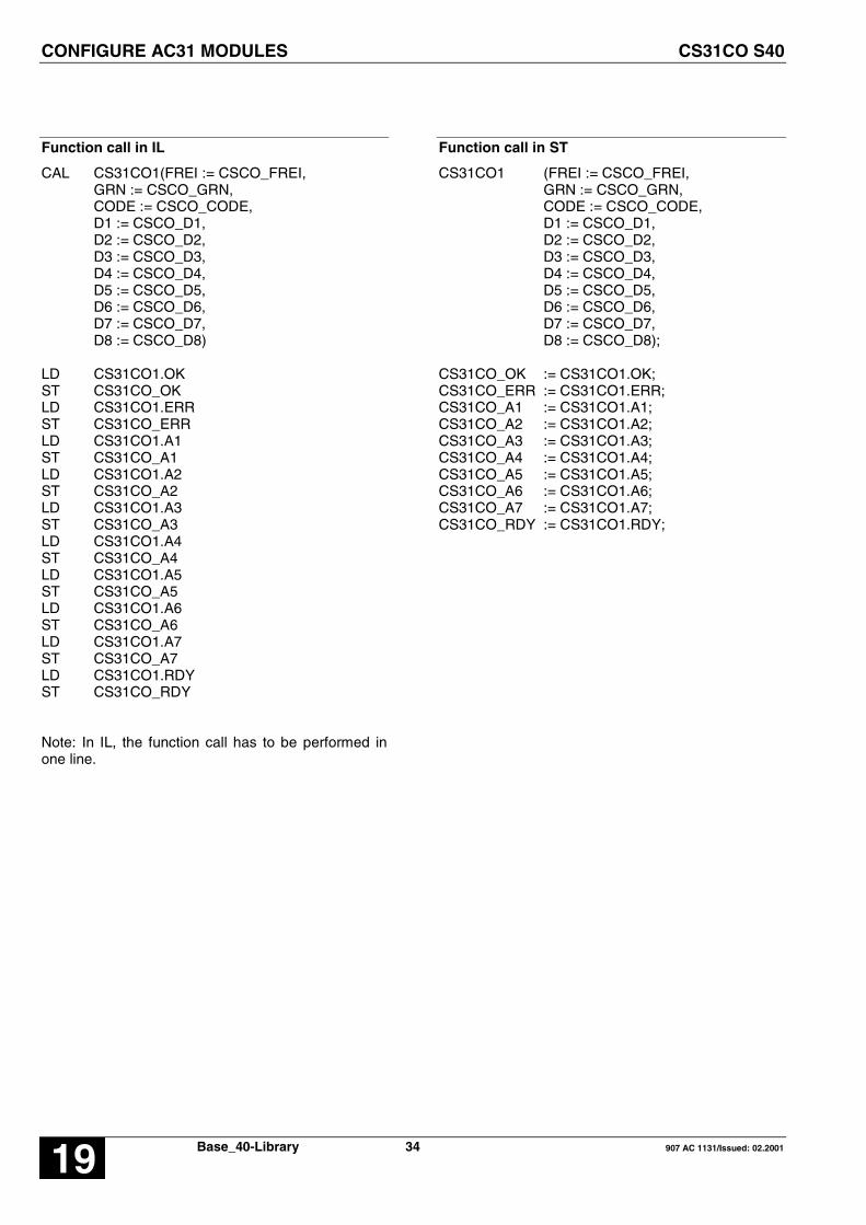
Function call in IL
CAL CS31CO1(FREI := CSCO_FREI,GRN := CSCO_GRN,CODE := CSCO_CODE,D1 := CSCO_D1,D2 := CSCO_D2,D3 := CSCO_D3,D4 := CSCO_D4,D5 := CSCO_D5,D6 := CSCO_D6,D7 := CSCO_D7,D8 := CSCO_D8)
LD CS31CO1.OKST CS31CO_OKLD CS31CO1.ERRST CS31CO_ERRLD CS31CO1.A1ST CS31CO_A1LD CS31CO1.A2ST CS31CO_A2LD CS31CO1.A3ST CS31CO_A3LD CS31CO1.A4ST CS31CO_A4LD CS31CO1.A5ST CS31CO_A5LD CS31CO1.A6ST CS31CO_A6LD CS31CO1.A7ST CS31CO_A7LD CS31CO1.RDYST CS31CO_RDY
Note: In IL, the function call has to be performed inone line.
Function call in ST
CS31CO1 (FREI := CSCO_FREI,GRN := CSCO_GRN,CODE := CSCO_CODE,D1 := CSCO_D1,D2 := CSCO_D2,D3 := CSCO_D3,D4 := CSCO_D4,D5 := CSCO_D5,D6 := CSCO_D6,D7 := CSCO_D7,D8 := CSCO_D8);
CS31CO_OK := CS31CO1.OK;CS31CO_ERR := CS31CO1.ERR;CS31CO_A1 := CS31CO1.A1;CS31CO_A2 := CS31CO1.A2;CS31CO_A3 := CS31CO1.A3;CS31CO_A4 := CS31CO1.A4;CS31CO_A5 := CS31CO1.A5;CS31CO_A6 := CS31CO1.A6;CS31CO_A7 := CS31CO1.A7;CS31CO_RDY := CS31CO1.RDY;

ACKNOWLEDGE AC31 ERRORS CS31QU S40
907 AC 1131/Issued: 02.2001 35 Base_S40-Library 19
ACKNOWLEDGE AC31 ERRORS CS31QU S40
This block allows to acknowledge automatically errormessages of AC31 remote modules.
Block type
Function block without historical values
Parameters
Instance CS31QU Instance nameFREI BOOL Enabling of the block processing
Description
This function block allows to acknowledgeautomatically FK3 and FK4 error messages of AC31remote modules. Error messages are stored on theAC31 remote modules until they are acknowledged.Even if the error has been removed, the error messageis still pending on the module until acknowledgementand is also signalized to the PLC until the message isacknowledged.
Processing of the block is enabled with a TRUE signalat input FREI, and the block then acknowledges AC31errors continuously until the signal at the input FREIchanges from TRUE to FALSE.
It may take several PLC cycles to acknowledge anerror on an AC31 module.
If the function block is enabled, it constantly checkswhether an AC31 error of class 3 or 4 has occurred andacknowledges this error.
1. An AC31 error of class 3 has occurred:
The block acknowledges the error on the AC31remote module which signalizes the error and alsoclears the error message on the PLC, i.e. the errorflag M255,13 / MX255.13 is reset and LED FK3 isdeactivated.
Example of a FK3 error:– a remote module is disconnected from the CS31
system bus.
2. An AC31 error of class 4 has occurred:
The block acknowledges the error on the AC31remote module which signalizes the error and alsoclears the error message on the PLC, i.e. the errorflag M255,14 / MX255.14 is reset.
Example of a FK4 error:– a remote module signalizes an open circuit

ACKNOWLEDGE AC31 ERRORS CS31QU S40
Base_40-Library 36 907 AC 1131/Issued: 02.200119
Example
Declaration:
CS31QU_1 : CS31QU;CS31QU_FREI AT %IX62.0 : BOOL;
Translation in ABB IL:
!BA 0CS31QUFREI
FBD: ABB IL of example:
!BA 0CS31QUE62,0
Function call in IL
CAL CS31QU_1(FREI := CS31QU_FREI)
Function call in ST
CS31QU_1(FREI := CS31QU_FREI);
UP COUNTER CTU S40
907 AC 1131/Issued: 02.2001 37 Base_S40-Library 19
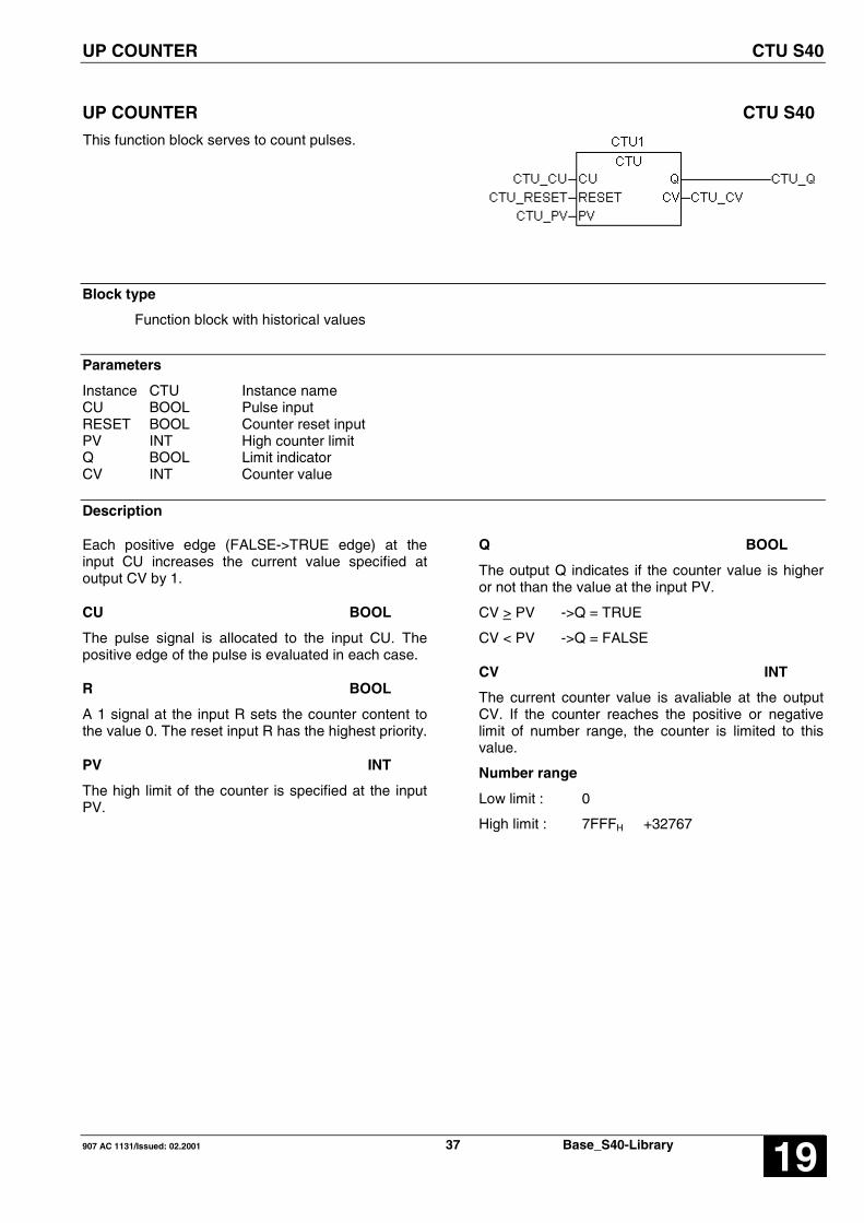
UP COUNTER CTU S40
This function block serves to count pulses.
Block type
Function block with historical values
Parameters
Instance CTU Instance nameCU BOOL Pulse inputRESET BOOL Counter reset inputPV INT High counter limitQ BOOL Limit indicatorCV INT Counter value
Description
Each positive edge (FALSE->TRUE edge) at theinput CU increases the current value specified atoutput CV by 1.
CU BOOL
The pulse signal is allocated to the input CU. Thepositive edge of the pulse is evaluated in each case.
R BOOL
A 1 signal at the input R sets the counter content tothe value 0. The reset input R has the highest priority.
PV INT
The high limit of the counter is specified at the inputPV.
Q BOOL
The output Q indicates if the counter value is higheror not than the value at the input PV.
CV > PV ->Q = TRUE
CV < PV ->Q = FALSE
CV INT
The current counter value is avaliable at the outputCV. If the counter reaches the positive or negativelimit of number range, the counter is limited to thisvalue.
Number range
Low limit : 0
High limit : 7FFFH +32767

UP COUNTER CTU S40
Base_40-Library 38 907 AC 1131/Issued: 02.200119
Example
Declaration:
CTU1: CTU;CTU_CU AT %MX1.0: BOOL;CTU_RESET AT %MX0.0 : BOOL;CTU_PV %MW3002.0 : INT := 1000;CTU_Q AT %MX1.1 : BOOL;CTU_CV AT %MW1002.2 : INT;
Translation in ABB IL:
!BA 0CTUCURESETPVQCV
FBD: ABB IL of example:
!BA 0CTUM1,0M0,0KW2,0 ; 1000M1,1MW2,2
Function call in IL
CAL CTU_1(CU := CTU_CU,RESET := CTU_RESET,PV := CTU_PV)
LD CTU_1.QST CTU_QLD CTU_1.CVST CTU_CV
Note: In IL, the function call has to be performed inone line.
Function call in ST
CTU ( CU= CTU_CU,RESET:= CTU_RESET,PV := CTU_PV);
CTU_Q := CTU_1.Q;CTU_CV := CTU_.CV;

HIGH SPEED COUNTER CTUH S40
907 AC 1131/Issued: 02.2001 39 Base_S40-Library 19
HIGH SPEED COUNTER CTUH S40
The CTUH function block allows the counting ofhigh speed counters of units series 40 and 50.
Block type
Function block with historical values
Parameters
Instance CTUH Instance nameNUM INT Counter modeRE BOOL Counter reset inputSE BOOL Counter set inputINIT INT Set valueRPI BOOL Reset point indicatorCATCH BOOL Catch counter valueR_Q BOOL Reset bit overflowQ BOOL OverflowCV INT Counter valueCATV INT Caught counter value
Description
Units series 40..50 have two high speed counters thatcan be used in the following modes :
- C1 : counting on the %IX62.00 input
Counting start: on positive edge(FALSE->TRUE edge)Representation:1 INT (16 bits)Overflow : when passing from -1 to 0.Capture : on positive edge of the %IX62.02 input
- C2 : counting on the %IX62.01 input
Counting start : on positive edge (FALSE->TRUE edge)Representation:1 INT (16 bits)Overflow : when passing from -1 to 0.Capture : on positive edge of the %IX62.03 input
- Incremental encoder : counting on the %IX62.00and %IX62.01 inputs
Counting start : on positive edge (FALSE/TRUE edge)Representation:1 INT (16 bits)Overflow : when passing from -1 to 0
or from 0 to -1Capture : on positive edge of the %IX62.02 input
In case of defective channel (i. e. one input notconnected) the value increases of +1 anddecreases of -1.
NUM DIRECT CONSTANT
The counting mode is specified at the input NUM.1 = counter mode C12 = counter mode C23 = incremental encoder>3 = the block is not processed
R BOOL
A TRUE signal at the input R resets the counter valueand the capture register to the value 0. The reset inputR has the highest priority.If R = TRUE then CV = 0 and CATV = 0
S BOOL
A TRUE signal at the input S loads the counter valuewith the preset value specified at the input INIT.If S = TRUE then CV = INIT

HIGH SPEED COUNTER CTUH S40
Base_40-Library 40 907 AC 1131/Issued: 02.200119
INIT INT
The preset value is specified at the input INIT.
RPI BOOL
A TRUE signal at the input RPI validates the countervalue capture and the counter reset during the capture.The RPI input has a higher priority than CATCH.
RPI = TRUE Capture is valid on all the counters.
If there is a positive edge on %IX62,02 or %IX62,03,there is a hard capture of the counter. The counter isreset to 0.
CATCH BOOL
A TRUE signal at the input CATCH validates thecounter value capture.
CATCH = 0 Capture not valid
CATCH = 1 Capture is valid on all the counters.
If there is a positive edge on %IX62,02 or %IX62,03,there is a hard capture of the counter. The counter isnot reset to 0.
R_Q BOOL
A TRUE signal at the input R_Q resets the overflow tothe value FALSE.
If R_Q = TRUE then Q = FALSE
Q BOOL
The overflow is specified at the output Q.
Q = TRUE when CV passes from -1 to 0 or from 0 to -1.
CV INT
The current counter value is available at the output CV.
CATV INT
The counter value when CATCH = TRUE is available atthe output CATV.
Number range:
Integer word (16 bits)
Low limit : 8000H - 32768
High limit : 7FFFH + 32767

HIGH SPEED COUNTER CTUH S40
907 AC 1131/Issued: 02.2001 41 Base_S40-Library 19
Example
Declaration:
CTUH_1: CTUH;CTUH_RE AT %MX1.0: BOOL;CTUH_SE AT %MX1.1: BOOL;CTUH_INIT AT %MW3002.0: INT := 100;CTUH_RPI AT %MX1.2: BOOL;CTUH_CATCH AT %MX1.3: BOOL;CTUH_R_Q AT %MX1.4: BOOL;CTUH_Q AT %MX1.5: BOOL;CTUH_CV AT %MW1010.0: INT;CTUH_CATV AT %MW1010.1: INT;
Translation in ABB IL:
!BA 0CTUH#NUMRESEINITRPICATCHR_QQCVCATV
FBD: ABB IL of example:
!BA 0CTUH#1M1,0M1,1KW2,0 ; 100M1,2M1,3M1,4M1,5MW10,0MW10,1
Function call in IL
CAL CTUH1( NUM := 01,RE := CTUH_RE,SE := CTUH_SE,INIT := CTUH_INIT,RPI := CTUH_RPI,CATCH := CTUH_CATCH,R_Q := CTUH_R_Q)
LD CTUH1.QST CTUH_QLD CTUH1.CVST CTUH_CVLD CTUH1.CATVST CTUH_CATV
Function call in ST
CTUH1 ( NUM := 01,RE := CTUH_RE,SE := CTUH_SE,INIT := CTUH_INIT,RPI := CTUH_RPI,CATCH := CTUH_CATCH,R_Q := CTUH_R_Q);
CTUH_Q := CTUH1.Q;CTUH_CV := CTUH1.CV;CTUH_CATV := CTUH1.CATV;
READ DIRECT INPUTS DIN S40
Base_40-Library 42 907 AC 1131/Issued: 02.200119
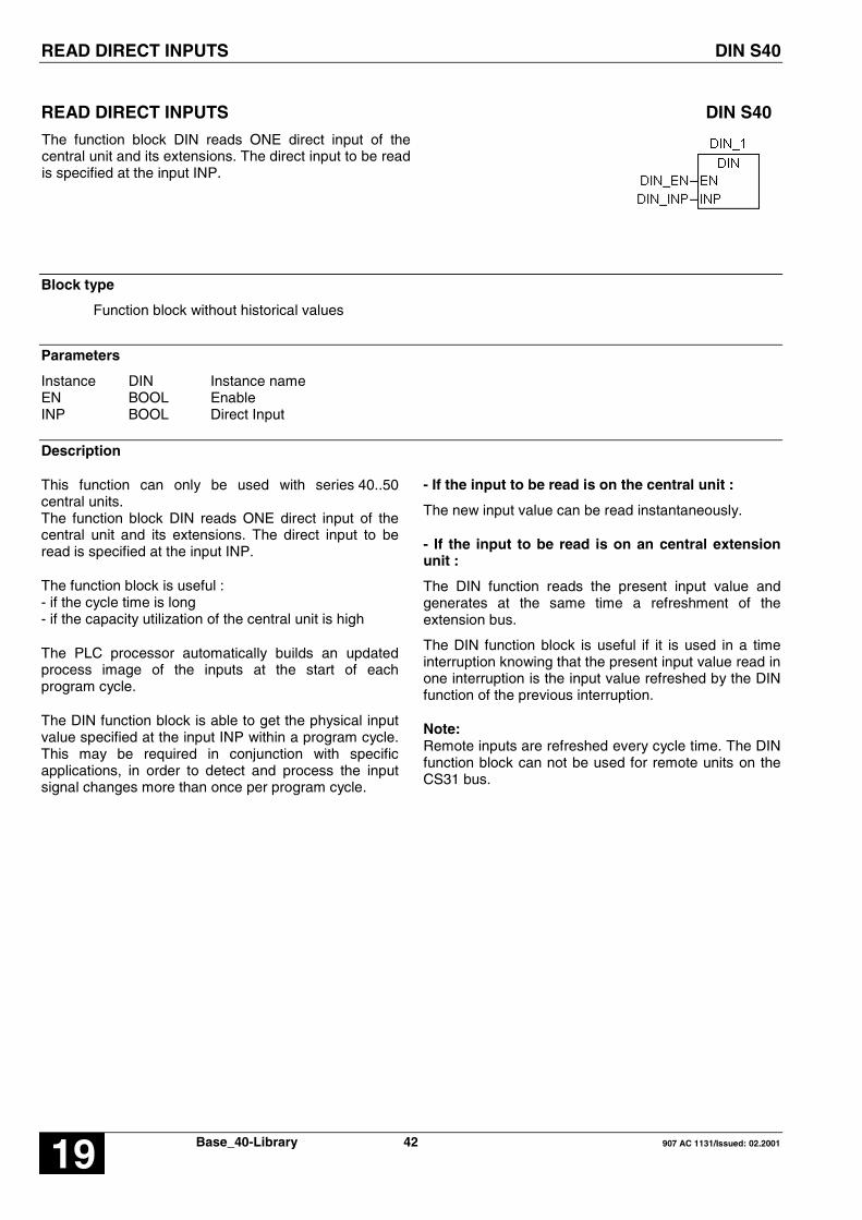
READ DIRECT INPUTS DIN S40
The function block DIN reads ONE direct input of thecentral unit and its extensions. The direct input to be readis specified at the input INP.
Block type
Function block without historical values
Parameters
Instance DIN Instance nameEN BOOL EnableINP BOOL Direct Input
Description
This function can only be used with series 40..50central units.The function block DIN reads ONE direct input of thecentral unit and its extensions. The direct input to beread is specified at the input INP.
The function block is useful :- if the cycle time is long- if the capacity utilization of the central unit is high
The PLC processor automatically builds an updatedprocess image of the inputs at the start of eachprogram cycle.
The DIN function block is able to get the physical inputvalue specified at the input INP within a program cycle.This may be required in conjunction with specificapplications, in order to detect and process the inputsignal changes more than once per program cycle.
- If the input to be read is on the central unit :
The new input value can be read instantaneously.
- If the input to be read is on an central extensionunit :
The DIN function reads the present input value andgenerates at the same time a refreshment of theextension bus.
The DIN function block is useful if it is used in a timeinterruption knowing that the present input value read inone interruption is the input value refreshed by the DINfunction of the previous interruption.
Note:Remote inputs are refreshed every cycle time. The DINfunction block can not be used for remote units on theCS31 bus.

READ DIRECT INPUTS DIN S40
907 AC 1131/Issued: 02.2001 43 Base_S40-Library 19
Example
Declaration:
DIN_1 : DIN;DIN_EN AT %MX0.0 : BOOL;DIN_INP AT %IX62.0 : BOOL;
Translation in ABB IL:
!BA 0DIENINP
FBD: ABB IL of example:
!BA 0DIM0,0E62,0
Function call in IL
CAL DIN_1(EN := DIN_EN,INP := DIN_INP)
Function call in ST
DIN_1 (EN := DIN_EN,INP := DIN_INP);
DIVISION DOUBLE WORD DIVD S40
Base_40-Library 44 907 AC 1131/Issued: 02.200119
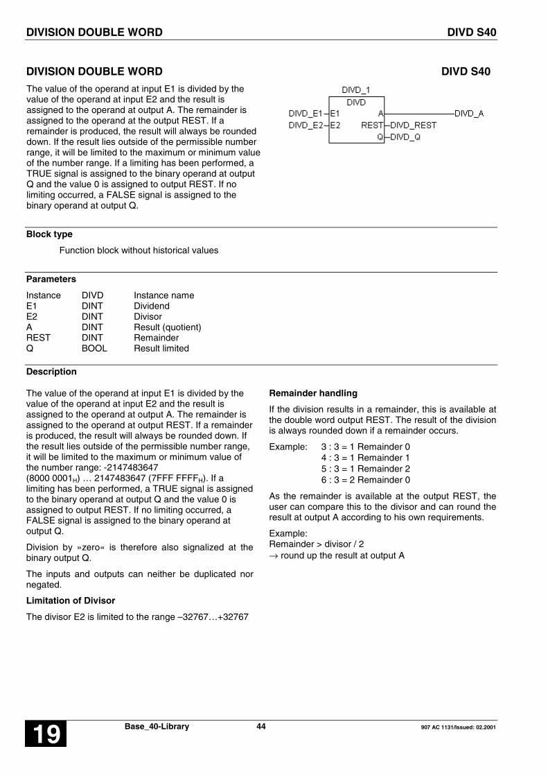
DIVISION DOUBLE WORD DIVD S40
The value of the operand at input E1 is divided by thevalue of the operand at input E2 and the result isassigned to the operand at output A. The remainder isassigned to the operand at the output REST. If aremainder is produced, the result will always be roundeddown. If the result lies outside of the permissible numberrange, it will be limited to the maximum or minimum valueof the number range. If a limiting has been performed, aTRUE signal is assigned to the binary operand at outputQ and the value 0 is assigned to output REST. If nolimiting occurred, a FALSE signal is assigned to thebinary operand at output Q.
Block type
Function block without historical values
Parameters
Instance DIVD Instance nameE1 DINT DividendE2 DINT DivisorA DINT Result (quotient)REST DINT RemainderQ BOOL Result limited
Description
The value of the operand at input E1 is divided by thevalue of the operand at input E2 and the result isassigned to the operand at output A. The remainder isassigned to the operand at output REST. If a remainderis produced, the result will always be rounded down. Ifthe result lies outside of the permissible number range,it will be limited to the maximum or minimum value ofthe number range: -2147483647(8000 0001H) … 2147483647 (7FFF FFFFH). If alimiting has been performed, a TRUE signal is assignedto the binary operand at output Q and the value 0 isassigned to output REST. If no limiting occurred, aFALSE signal is assigned to the binary operand atoutput Q.
Division by »zero« is therefore also signalized at thebinary output Q.
The inputs and outputs can neither be duplicated nornegated.
Limitation of Divisor
The divisor E2 is limited to the range –32767…+32767
Remainder handling
If the division results in a remainder, this is available atthe double word output REST. The result of the divisionis always rounded down if a remainder occurs.
Example: 3 : 3 = 1 Remainder 04 : 3 = 1 Remainder 15 : 3 = 1 Remainder 26 : 3 = 2 Remainder 0
As the remainder is available at the output REST, theuser can compare this to the divisor and can round theresult at output A according to his own requirements.
Example:Remainder > divisor / 2→ round up the result at output A

DIVISION DOUBLE WORD DIVD S40
907 AC 1131/Issued: 02.2001 45 Base_S40-Library 19
Division by »zero«
If the divisor has the value »zero«, the positive ornegative limit of the number range is assigned to outputA.
For the division by »zero« the following applies:
A = -2147483647 (8000 0001H) if dividend is negativeA = +2147483647 (7FFF FFFFH) if dividend is positive
REST = 0 Output for the remainder
Q = TRUE Output to signalize that the value at outputA has been limited
Invalid result value
If the invalid value 8000 0000H is the result of thedivision, this will be corrected to the permissible limit8000 0001H (-2 147 483 647), the binary output Q willbe set to the value TRUE and the output REST will beset to the value 0.
Example
Declaration:
DIVD_1 : DIVD;DIVD_E1 AT %MD2002.0 : DINT;DIVD_E2 AT %MD2002.1 : DINT;DIVD_A AT %MD2002.2 : DINT;DIVD_REST AT %MD2002.3 : DINT;DIVD_Q AT %MX0.0 : BOOL;
Translation in ABB IL:
!BA 0DIVDE1E2ARESTQ
FBD: ABB IL of example:
!BA 0DIVDMD2,0MD2,1MD2,2MD2,3M0,0
Function call in IL
CAL DIVD1(E1 := DIVD_E1,E2 := DIVD_E2)
LD DIVD1.RESTST DIVD_RESTLD DIVD1.QST DIVD_QLD DIVD1.AST DIVD_A
Function call in ST
DIVD1 (E1 := DIVD_E1,E2 := DIVD_E2);
DIVD_REST :=DIVD1.REST;DIVD_Q :=DIVD1.Q;DIVD_A :=DIVD1.A;

WRITE DIRECT OUTPUTS DOUT S40
Base_40-Library 46 907 AC 1131/Issued: 02.200119
WRITE DIRECT OUTPUTS DOUT S40
The function block DOUT writes ONE direct output of thecentral unit and its extensions. The direct output to bewrite is specified at the input OUT.
Block type
Function block without historical values
Parameters
Instance DOUT Instance nameEN BOOL EnableOUT BOOL Direct Output
Description
The function block DOUT writes ONE direct output ofthe central unit or its extension. The direct output tobe written is specified at the output OUT.
The function block is useful :- if the cycle time is long- if the capacity utilization of the central unit is high
The PLC processor automatically outputs a processimage of the direct outputs, which was updatedduring the program cycle, at the end of each programcycle. The DOUT function block is able to set thephysical output specified at the OUT parameter withinprogram cycles. This may be required in conjunctionwith specific applications, in order to have availablethe output signal changes more than once perprogram cycle.
If the output to be written is on the central unit :
The new output value can be write instantaneously.
If the output to be written is on an extension unit :
The new output value can be write with a delay ofmax 2 ms.
Note:Remote outputs are refreshed every cycle time. TheDOUT function block can not be used for remoteoutputs.

WRITE DIRECT OUTPUTS DOUT S40
907 AC 1131/Issued: 02.2001 47 Base_S40-Library 19
Example
Declaration:
DOUT_1 : DOUT;DOUT_EN AT %MX0.0 : BOOL;DOUT_OUT AT %QX62.0 : BOOL;
Translation in ABB IL:
!BA 0DOENOUT
FBD: ABB IL of example:
!BA 0DOM0,0A62,0
Function call in IL
CAL DOUT_1(EN := DOUT_EN)
LD DOUT_1.OUTST DOUT_OUT
Function call in ST
DOUT_1 (EN := DOUT_EN);
DOUT_OUT := DOUT_1.OUT;

OUTPUT OF ASCII CHARACTERS DRUCK S40
Base_40-Library 48 907 AC 1131/Issued: 02.200119
OUTPUT OF ASCII CHARACTERS DRUCK S40
A central unit of S40..50 can send ASCII messagesthrough its RS232 serial interface with the DRUCKfunction block.
Each message has an identification number and can becomposed of ASCII texts and operands values.
The texts and operand identifiers to be output are storedin the user program in the PLC directly by the DRUCKblock. The numerical values to be output are conditionedfor a diversity of representations by specifying a formatidentifier.
The block DRUCK is only in IL and ST available !
{S40Inline!BA 0DRUCKFREITXNRSSKRDYTX}
Block type
ABB IL Program block inside Pragma
Parameters
ABB IL Type DescriptionFREI BOOL Enable signal for output of one text (FALSE/TRUE
edge )SSK INT Serial interface identificationTXNR INT Number of the text to be outputRDY BOOL ReadyTX Texts Texts/operands capable of duplication
Description
IMPORTANT NOTE :Initialization of the serial interface
Before the DRUCK block can communicate with theserial interface, it must be initialized with the SINITblock.
Communication between several DRUCK blocksand the same serial interface:
Several DRUCK blocks can use the same serialinterface. If the serial interface is engaged by one ofthe DRUCK blocks, the other DRUCK blocksautomatically wait until it is free again. The priorityaccess to the serial interface when several DRUCKblocks simultaneously have access to the sameinterface, corresponds to the sequence in which theDRUCK blocks are called in the user program : thefirst DRUCK block located at the beginning of theuser program is given access first. The processingsequence must be planned by an appropriate mutualinterlocking of the DRUCK blocks.
Communication by a DRUCK and EMAS blockwith the same serial interface:
A DRUCK block and a EMAS block (receiving ofASCII messages) can use the same serial interfacewithout any special precaution.
FREI BOOL
If the block is ready (RDY = TRUE) and aFALSE/TRUE edge appears at the FREI input, thetext identified at the input TXNR is sent through theserial interface specified at the SSK input.
If a FALSE/TRUE edge appears at the FREI inputalthough the RDY output is equal to FALSE (i. e. theblock is not ready yet for a new transfer), theFALSE/TRUE edge is ignored. Therefore, no newtext transfer is started as long as the RDY signal isFALSE.

OUTPUT OF ASCII CHARACTERS DRUCK S40
907 AC 1131/Issued: 02.2001 49 Base_S40-Library 19
SSK INT
Central units can have one or two RS232 serialinterface. The number of the interface through whichthe text is to be output is specified at the SSK input :
SSK = 1 for COM1SSK = 2 for COM2
TXNR INT
The number of the text to be output is specified at theTXNR input : 1 < TXNR < 99
The number of the text to be output must be presentat the TXNR input until the block indicates the end oftext transfer with a TRUE signal at its RDY output.
RDY BOOL
In the program cycle in which the block is called forthe first time, and during the time when a text isoutput, RDY is equal to FALSE. As long as RDY isequal to FALSE, no new text output can be activatedand all FALSE/TRUE edge present at the FREI inputare ignored and lost.
After the first call of the block or after termination of atext output, RDY is equal to TRUE and the block isready again for output of a new text.
FREI RDY TXNR
SSK MEANING
FALSE/TRUEedge
TRUE 2 1 The text withthe number 2is outputthroughinterface 1
FALSE/TRUEedge
FALSE 2 1 FALSE/TRUEedge is ignoredbecause theblock is notready
NoFALSE/TRUEedge
X X X No output of anew text
=> The RDY signal can be used for example at theFREI input to activate a new text transfer.
TX ALL
Texts and operands to be output are directly writtenat the TX inputs. The way to write the messages isdescribed here below.
Storage of texts in the central unit :
Quantity : 1...99 messagesLength : Up to 256 characters
(owing to the send buffer length = 256)
- Each text character counts as 1 character- Each format identifier counts as 3 characters
- Each bit operand counts as 1 character- Each word operand counts as 1 to 6 characters *- Each double word operand counts as 10 to 11characters ** depends on the format
When the program is started, the PLC checks thetexts to determine whether or not the maximumlength is exceeded.
Syntax of texts :
A text for the DRUCK block consists of :
- The text number
- One or several subtexts (optional)
- Operands with format identifier (optional)
#n : Number of the text to be entered as a
direct constant (1..99).
#" : Start identifier for text input.
“# : Stop identifier for text input
Subtext : All ASCII characters
(from hexadecimal code 00 up to 7F).
Operand : BOOL, INT or DINT operands whosevalues are output depending on thedisplay format.=> the operands must be written inABB IL format !
Format identifier :
The PLC is capable of presenting the numericalvalues to be output on a screen or a printer in diverseways. The format identifier specifies the type of theoperand and the display format of its value.
This is planned directly before the operand to beoutput and consists of three digits. The 1st digit fromthe left specifies the operand type. There are 3operand types :
BOOL : 1INT : 2DINT : 3
Numbers 2 and 3 define the display format.
Examples :
- Format identifier 103Digit 1 : 1 : BOOL operandDigits 2 and 3 : 03 : Display format 03 (see table)
-Format identifier 204Digit 1 : 2 : INT operandDigits 2 and 3 : 04 : Display format 04 (see table)

OUTPUT OF ASCII CHARACTERS DRUCK S40
Base_40-Library 50 907 AC 1131/Issued: 02.200119
- Format identifier 341Digit 1 : 3 : DINT operandDigits 2 and 3 : 41 : Display format 41 (see table)
Possible display formats :
All possible display formats are listed in the followingtable:
- identifiers applicable to word data types :01 to 16, 21 to 26, 33 to 36, 42 to 51, and 99
- identifiers applicable to double word data types :05 to 16 and 41 to 62
There are formats- with leading zeros and- with leading zeros substituted by blanks which areindicated in the table here below by -.
Format identifier ASCII output
Numerical example=001234567801 x 802 xx 7803 xxx 67804 xxxx 567805 xxxxx 45678
Numerical example=110221506 xxxx,x 0221,507 xxx,xx 022,1508 xx,xxx 02,21509 x,xxxx 0,221510 ,xxxxx ,02215
Numerical example=0033111 +/- xxxxx +0033112 +/- xxxx,x +0033,113 +/- xxx,xx +003,3114 +/- xx,xxx +00,33115 +/- x,xxxx +0,033116 +/- ,xxxxx +,00331
Numerical example=0023421 xxxxx --234
Numerical example=0034722 xxxx,x --34723 xxx,xx --3,4724 xx,xxx --,34725 x,xxxx -,034726 ,xxxxx ,00347
Numerical example=0034733 +/-xxx,xx +--3,4734 +/-xx,xxx +--,34735 +/-x,xxxx +-,034736 +/-,xxxxx +,00347
Numerical example=001234567841 xxxxxxxxxx 0012345678
Numerical example=001122334442 xxxxxxxxx,x 001122334,443 xxxxxxxx,xx 00112233,4444 xxxxxxx,xxx 0011223,34445 xxxxxx,xxxx 001122,334446 xxxxx,xxxxx 00112,2334447 xxxx,xxxxxx 0011,22334448 xxx,xxxxxxx 001,122334449 xx,xxxxxxxx 00,1122334450 x,xxxxxxxxx 0,01122334451 ,xxxxxxxxxx ,0011223344
Numerical example=005566778852 +/- xxxxxxxxxx +005566778853 +/- xxxxxxxxx,x +005566778,854 +/- xxxxxxxx,xx +00556677,8855 +/- xxxxxxx,xxx +0055667,78856 +/- xxxxxx,xxxx +005566,778857 +/- xxxxx,xxxxx +00556,6778858 +/- xxxx,xxxxxx +0055,66778859 +/- xxx,xxxxxxx +005,566778860 +/- xx,xxxxxxxx +00,5566778861 +/- x,xxxxxxxxx +0,05566778862 +/- ,xxxxxxxxxx +,0055667788
Special format :Output of a word operand’s HEX value :
The value of a INT operand is output directly as ahexadecimal value. Therefore, the value is notconverted to ASCII before output.98 Only the LOW BYTE (8 bits) of the word
operand is output99 The LOW BYTE of the word operand is
output first, followed by its HIGH BYTE
Important : This special format is only permissiblefor the "word" data type.Permissible format : 298 and 299Inadmissible format : 198, 199, 398 and 399

OUTPUT OF ASCII CHARACTERS DRUCK S40
907 AC 1131/Issued: 02.2001 51 Base_S40-Library 19
- Input of texts:
The following parts of the overall message aretreated as independent operands :- the text number e.g. # 1- a subtext e.g. #" Text1 “#- a format identifier e.g. # 203- an operand e.g. MW002,03- a further subtext e.g. #" Text2 “#
Input of special characters for screen or printercontrol :
Control characters such as "line feed" <LF> or"carriage return" <CR> are needed to arrange themessage when output to a screen or printer. Thesespecial characters can be placed anywhere within asubtext. In the programming system, these specialcharacters are entered by means of :
\Numerical value of the character
The numerical value of the character is specified as athree-digit decimal number.
Example :
The following output is to be made on a printer :
First lineBlank lineSecond line
To do this, the following text must be planned :First line <CR> <LF> <LF> second line
The following applies :<CR> = 013<LF> = 010
The text input in the programming system is asfollows :
#"First line\013\010\010second line”#
Notes :
- The characters with the ASCII code >20H (=32D)must be entered with the keyboard. As an example,the character "!" can be enteredwith the keyboard, and not as \033.
- Characters, which are not special characters andwhich can not be entered with the keyboard, can begenerated in the following way :Press and hold down the <ALT> key, now type thenumerical code (decimal code) on the numericalkeypad of the keyboard, then release the <ALT> key.
- The character with the ASCII code 255 is reservedfor internal use of the programming software andmust not be used otherwise.
- Example :
Text 1: The machine is readyText 2: The machine is not readyText 3: Level is (%MW1001.1=>MW01,01)m andtemperature is (%MW1001,0=>MW01,00)°C.
The Program will be in Instruction List :
LD 0{S40Inline!BA0DRUCKM0,0MW00,00MW00,01A00,00#01#"\010\013 The machine is ready : "##02#"\010\013 The machine is not ready. "##03#"\010\013 It is "##202MW01,01#"m and temperature is "##203MW01,00#"°C. "#}

DUAL TO BCD CONVERSION, WORD DUALBCD S40
Base_40-Library 52 907 AC 1131/Issued: 02.200119
DUAL TO BCD CONVERSION, WORD DUALBCD S40
The binary number at input E is converted to a BCDcoded number and assigned to the operand at outputA.
The binary number is represented in 16 bits and mustlie within the range 0 < E < 270FH (corresponding toBCD 9999). The BCD number is limited to 9999 if it liesoutside of this range. The BCD number is stored in a16 bit INT.
Block type
Function
Parameters
E INT Binary number(A) INT BCD coded number
Description
The binary number at input E is converted to a BCDcoded number and assigned to the operand at outputA.
The binary number is represented in 16 bits and mustlie within the range 0 < E < 270FH (corresponding toBCD 9999). The BCD number is limited to 9999 if it liesoutside of this range. The BCD number is stored in a16 bit INT.
The input and the output can neither be duplicated nornegated.
Definition:
The significance of the digits in a hexadecimal numberand a BCD coded number is defined as follows:
HEX NUMBER BCD NUMBER
15 11 7 3 0 BIT 15 11 7 3 0
Z4 Z3 Z2 Z1 Z4 Z3 Z2 Z1
Numerical value:Z1 * 1Z2 * 16Z3 * 256Z4 * 4096
Numerical value:Z1 * 1Z2 * 10Z3 * 100Z4 * 1000
0 < Zi < F 0 < Zi < 9

DUAL TO BCD CONVERSION, WORD DUALBCD S40
907 AC 1131/Issued: 02.2001 53 Base_S40-Library 19
Example
HEX NUMBER BCD NUMBER
15 11 7 3 0 BIT 15 11 7 3 0
0 4 D 2 -> 1 2 3 4
Z1 = 2 * 1 = 2
Z2 = 13 * 16 = 208
Z3 = 4 * 256 = 1024
Z4 = 0 * 4096 = 0
1234
Z1 = 4 * 1 = 4
Z2 = 3 * 10 = 30
Z3 = 2 * 100 = 200
Z4 = 1 * 1000 = 1000
1234
Conversion of a negative binary number to a BCDnumber
A negative binary number with an amount less than270FH can be converted to a BCD number, wherebythe value and the sign of the BCD number are eachstored in one flag.
Converting a binary number with an amount higherthan 270FH
Not available for S40..50.
Example
Declaration:
DUALBCD_E AT %MW1002.1 : INT;DUALBCD_A AT %MW1002.2 : INT;
Translation in ABB IL:
!BA 0BINBCDEA
FBD: ABB IL of example:
!BA 0BINBCDMW2,1MW2,2
Function call in IL
LD DUAL_EDUALBCDST DUAL_A
Function call in ST
DUAL_A:= DUALBCD(DUAL_E);

AND COMBINATION, DOUBLE WORD DWAND S40
Base_40-Library 54 907 AC 1131/Issued: 02.200119
AND COMBINATION, DOUBLE WORD DWAND S40
This function block generates, bit-by-bit, the ANDcombination of the operands present at the inputs E1and E2. The result is allocated to the operand at theoutput.
Block type
Function
Parameters
E1 DINT Operand 1E2 DINT Operand 2A DINT Result of the AND combination
Description
This function block generates, bit-by-bit, the ANDcombination of the operands present at the inputs E1and E2. The result is allocated to the operand at theoutput.
The inputs and outputs can neither be duplicated nornegated.
Example
Declaration:
DWAND_E1 AT %MD2000.0 : DINT;DWAND_E2 AT %MD2000.1 : DINT;DWAND_A AT %MD2000.2 : DINT;
Translation in ABB IL:
!BA 0DWANDE1E2A
FBD: ABB IL of example:
!BA 0DWANDMD0,0MD0,1MD0,2
Function call in IL
LD DWAND_E1DWAND DWAND_E2ST DWAND_A
Function call in ST
DWAND_A := DWAND(E1 := DWAND_E1,E2 := DWAND_E2);

OR COMBINATION, DOUBLE WORD DWOR S40
907 AC 1131/Issued: 02.2001 55 Base_S40-Library 19
OR COMBINATION, DOUBLE WORD DWOR S40
This function block generates, bit-by-bit, the ORcombination of the operands present at the inputs E1and E2. The result is allocated to the operand at theoutput.
Block type
Function
Parameters
E1 DINT Operand 1E2 DINT Operand 2A DINT Result of the OR combination
Description
This function block generates, bit-by-bit, the ORcombination of the operands present at the inputs E1and E2. The result is allocated to the operand at theoutput.
The inputs and outputs can neither be duplicated nornegated.
Example
Declaration:
DWOR_E1 AT %MD2000.0 : DINT;DWOR_E2 AT %MD2000.1 : DINT;DWOR_A AT %MD2000.2 : DINT;
Translation in ABB IL:
!BA 0DWORE1E2A
FBD: ABB IL of example:
!BA 0DWORMD0,0MD0,1MD0,2
Function call in IL
LD DWOR_E1DWOR DWOR_E2ST DWOR_A
Function call in ST
DWOR_A := DWOR(E1 := DWOR_E1,E2 := DWOR_E2);

DOUBLE WORD TO WORD CONVERSION DWW S40
Base_40-Library 56 907 AC 1131/Issued: 02.200119
DOUBLE WORD TO WORD CONVERSION DWW S40
The value of the double word operand at input E isconverted to a word variable and the result is assignedto the word operand at output A1.
Block type
Function block without historical values
Parameters
Instance DWW Instance nameE DINT Double word variable to be convertedA1 INT Result of conversion, word variableA2 BOOL Result limited
Description
The value of the double word operand at input E1 isconverted to a word variable and the result is assignedto the word operand at output A1.
The result is limited to the maximum or minimumnumber range.
max. number range: +32767 (7FFFH)min. number range: -32767 (8001H)
If limiting occurred, a TRUE signal is assigned to thebinary operand at output A2. If no limiting occurred, aFALSE signal is assigned to the binary operand atoutput A2.
The input and the outputs can neither be duplicated nornegated.
Example
Declaration:
DWW_1 : DWWDWW_E AT %MD2000.0 : DINT;DWW_A1 AT %MW1000.0 : INT;DWW_A2 AT %MW1000.1 : INT;
Translation in ABB IL:
!BA 0DWWEA1A2
FBD: ABB IL of example:
!BA 0DWWMD0,0MW0,0MW0,1
Function call in IL
CAL DWW_1(E := DWW_E)
LD DWW_1.A2ST DWW_A2LD DWW_1.A1ST DWW_A1
Function call in ST
DWW_1 (E := DWW_E);
DWW_A2 := DWW_1.A2;DWW_A1 := DWW_1.A1;

XOR COMBINATION, DOUBLE WORD DWXOR S40
907 AC 1131/Issued: 02.2001 57 Base_S40-Library 19
XOR COMBINATION, DOUBLE WORD DWXOR S40
This function block generates, bit-by-bit, the XORcombination of the operands present at the inputs E1and E2. The result is allocated to the operand at theoutput.
Block type
Function
Parameters
E1 DINT Operand 1E2 DINT Operand 2A DINT Result of the XOR combination
Description
This function block generates, bit-by-bit, the XORcombination of the operands present at the inputs E1and E2. The result is allocated to the operand at theoutput.
The inputs and outputs can neither be duplicated nornegated.
Example
Declaration:
DWXOR_E1 AT %MD2000.0 : DINT;DWXOR_E2 AT %MD2000.1 : DINT;DWXOR_A AT %MD2000.2 : DINT;
Translation in ABB IL:
!BA 0DWXORE1E2A
FBD: ABB IL of example:
!BA 0DWXORMD0,0MD0,1MD0,2
Function call in IL
LD DWXOR_E1DWXOR DWXOR_E2ST DWXOR_A
Function call in ST
DWXOR_A := DWXOR(E1 := DWXOR_E1,E2 := DWXOR_E2);

RECEPTION OF ASCII CHARACTERS EMAS S40
Base_40-Library 58 907 AC 1131/Issued: 02.200119
RECEPTION OF ASCII CHARACTERS EMAS S40
The function block EMAS:
- receives telegram through a serial interface of thePLC
- compares these telegrams to comparisiontelegrams stored in the user program
- and, if these agree, provides the user data of thetelegram received at the block’s outputs.
The block EMAS is only in IL and ST available !
{S40Inline!BA 0EMASQUITSSK#ANUMEUNRDYTELNMW0VT0}
Block type
ABB IL Program block inside Pragma
Parameters
ABB IL Type DescriptionQUIT BOOL Reception of telegrams not enabled.SSK INT Serial interface identification#ANU Direct
constantNumber of outputs for user information;in format: #number
MEUN BOOL Data invalidRDY BOOL Ready : telegram has been receivedTELN INT Number of the comparison telegram with which the
received one agreesMW0 INT User data; in ABB IL formatVT0 Texts Comparison telegram; capable of duplication
Description
ASCII communication function block.
A AC31 central unit can receive ASCII messagesthrough its RS232 serial interface with the EMASfunction block.
The EMAS function block :- receives telegrams through a serial interface of thePLC- compares these telegrams to comparison telegramsstored in the user program- and, if these agree, provides the user data of thetelegram received at the block's outputs.
The received telegrams are fetched from the serialinterface by an interface driver and are provided in aBUFFER for further processing by EMAS. The driverrecognizes the end of the telegram by the end oftelegram character. This end of telegram character isplanned in the SINIT block.
IMPORTANT NOTE :Initialization of the serial interface.
Before using the EMAS block, the serial interfaceused has to be initialized with the SINIT block.
Communication between several EMAS blocksand the same serial interface :
- EMAS blocks of a user program which access thesame serial interface must be interlocked so that onlyever one EMAS block is active. If this is not done,telegrams may be processed by the wrong EMASand declared invalid.
- If both user program 1 and also user program 2contain EMAS blocks which access the same serialinterface, they must be interlocked so that only everone EMAS block is active. If this is not done,telegrams may be processed by the wrong EMASand declared invalid.
A telegram loss can be avoided by interlocking of theEMAS blocks. Interlocking must be planned so thatonly the EMAS block is enabled for which thetelegram arriving through the interface is intended.

RECEPTION OF ASCII CHARACTERS EMAS S40
907 AC 1131/Issued: 02.2001 59 Base_S40-Library 19
Communication by an EMAS block and a DRUCKblock with the same serial interface:
An EMAS and a DRUCK block can use the sameserial interface without special precautions having tobe taken.
QUIT BOOL
The input QUIT controls reception of telegrams andalso serves the purpose of acknowledgement in theevent of an error occurring.
QUIT = FALSE : Reception of telegrams enabled.QUIT = TRUE : Reception of telegrams not
enabled. Acknowledgment afterreception of an invalid telegram.
If agreement with none of the stored comparisontelegrams is ascertained on comparison of a receivedtelegram, the EMAS automatically assumes the"error" state. In this case, EMAS no longer processesany new telegrams until the error is acknowledgedwith a 1 signal at the input QUIT and reception oftelegrams is enabled again (next cycle) with a 0signal at the input QUIT.
SSK INT
The number of the interface through which the blockreceives its telegrams is specified at the SSK input(interface identifier).The following applies :COM1 : number = 1COM2 : number = 2
#ANU DIRECT CONSTANT
The number of outputs MW0 at which the blockprovides the received user information is specified atthe input #ANU (number of user information items).This is specified as a direct constant.I. e. numer =10 => #ANU = #10 or #H0A
MEUN BOOL
The output MEUN (flag invalid) indicates whether ornot the data at the outputs MW is valid or invalid.If a telegram is received and processed properly, thedata at the outputs MW is declared valid.The data at the outputs MW is declared invalid if thereceived telegram does not agree with any of thestored comparison telegrams or if the receivedtelegram cannot be processed properly.MEUN = FALSE -> Data at the outputs MW is validMEUN = TRUE -> Data at the outputs MW is invalid
RDY BOOL
The output RDY (ready) indicates that a telegram hasbeen received and processed.The output RDY does not provide any information asto whether or not a valid or invalid telegram has beenreceived.RDY = FALSE -> Still no telegram has been
receivedRDY = TRUE -> A telegram has been received and
processed
QUIT MEUN RDY MeaningTRUE FALSE FALSE The EMAS is disabled by
QUIT=TRUE. In doing so,the outputs MEUN and RDYare permanently set toFALSE.
FALSE TRUE FALSE EMAS is enabled forreception, but still notelegram has been receivedand evaluated.
FALSE TRUE TRUE EMAS has received a validtelegram and is ready toreceive a new telegram.
FALSE TRUE TRUE EMAS has received aninvalid telegram. Anacknowledgement at theQUIT input is necessary inorder to be able to receive anew telegram.QUIT: FALSE->TRUE edge
FALSE->TRUEedge
FALSE TRUE Acknowledgement afterreception of an invalidtelegram. Afteracknowledgement, theEMAS is enabled again byQUIT=FALSE
TELN INT
If a valid telegram is received, the number of theaffiliated comparison telegram is output through theoutput TELN (telegram number).
MW0 INT
The output MW0 can be duplicated. The user datacommunicated in the telegram currently received isoutput through the MW0 parameters. This user datamay consist of numerical values or any characters.This depends on which kind of dummy parametershave been planned in the comparison telegram. Theuser data of a telegram is stored beginning with thefirst MW parameter and in the sequence in whichthey are planned in the comparison telegram. Asmany outputs MW0 must be provided as aresufficient for the telegram with the most user data.=> the operands must be written in ABB ILformat !

RECEPTION OF ASCII CHARACTERS EMAS S40
Base_40-Library 60 907 AC 1131/Issued: 02.200119
VT0 ALL in IL
The comparison telegrams to be stored in the PLCprogram are specified at the inputs VT0. The block iscapable of processing from 1 to 99 telegrams. Onetelegram occupies 2 inputs, each telegram numberbeing specified at one input and the actual telegramtext being specified at the next one. The exact syntaxand handling of the comparison telegrams aredescribed here below.The way to write the messages is described herebelow and an example is given at the end.
Detailed description of Comparison telegrams
1...99 comparison telegrams are stored directly afterthe EMAS block.
The comparison telegrams serve to identify- the current telegrams received- and the user data contained in the telegramsreceived
Each stored comparison telegram has a telegramnumber to identify it and may comprise up to 255characters.
The comparison telegrams consist of :- ASCII characters serving only to identify thetelegram received,- Dummy parameters for the user information to bereceived and to be output through the block’soutputs.
As regards the dummy parameters for the userinformation, EMAS function block distinguishesbetween dummy parameters for digits and dummyparameters for characters.
Dummy parameter for digits :# (1 # per digit)
Dummy parameter. for characters :* (1 * per character/byte)
Dummy parameter for digits :For each dummy digit parameter (#) of thecomparison telegram, EMAS expects precisely oneASCII coded decimal digit in the telegram to bereceived. Up to 5 dummy digits constitute onedummy parameter group. Such a group of dummydigits represents the numerical value of a decimalnumber comprising up to 5 digits.
No dummy parameter is specified for the decimalnumber’s sign because EMAS takes it into accountautomatically. The EMAS allocates one userinformation output to each numerical value belongingto a dummy parameter group.
E.g. :Decimalnumber
Dummyparameters
1234 ####+1234 ####-1234 ####
The EMAS block checks the received decimalnumber in relation to its significant range. Onlynumbers within the +32767 range can be processedin the PLC. If the received decimal number exceedsthe significant range, the EMAS will automaticallyinsert the maximum respective limit. The limit for apositive number is +32767 and the limit is -32767 fora negative number.
Dummy parameter for characters :For each dummy character (*) of the comparisontelegram, EMAS expects any one character/byte inthe telegram to be received. These may compriseASCII characters of letters, but also all other hexvalues from 0...FF.The length of a dummy character group is up to 255.If this were the case, the complete comparisontelegram would consist of dummy characters only.EMAS allocates the characters/bytes receivedwithout change and successively to its userinformation outputs MW0.
Syntax diagram : Structure of comparison telegrams
#n #" *
#
T EXT
#n : Successive telegram number(direct constant 1...99)
#" : Start identifier for text input
“# : Stop identifier for text input
* : Dummy parameter for character/byte
# : Dummy parameter for digits
TEXT : All ASCII characters 01 to FF except * and #

RECEPTION OF ASCII CHARACTERS EMAS S40
907 AC 1131/Issued: 02.2001 61 Base_S40-Library 19
Input of comparison telegrams
- Each comparison telegram consists of :the telegram numberthe telegram text
The telegram number and the telegram text are twoseparate operands. This is why the telegram numberand the telegram text occupy separate inputs in theFBD symbol of the EMAS block.Therefore, two inputs are needed for one comparisontelegram.
Example :
First TEXT Input : #1(No. of the first comparison telegram)Second TEXT Input : #"PRINT###IDENTIFIER**** (Text of the first comparisontelegram)
- Apart from the ASCII characters for * and #, allASCII characters are possible in the telegram text.
- When entering special ASCII characters such as"start of line" <CR>, the following must be observed :special characters are entered by :
\Numerical value of the character
The character’s numerical value is specified as athree-digit decimal number.
Example for the EMAS block:
The following telegram text is to be compared :Temperature <CR> boiler 1The following applies : <CR> = 013
The text input in the programming system is asfollows :
#"temperature\013boiler 1
Note :
- The characters with the ASCII code >20H or >32Dmust be entered with the keyboard. As an example,the character "!" must be entered with the keyboard,and not as \033.- Characters, which are no special characters andwhich also could not be entered with the keyboard,can be generated in the following way :Press and hold down the <ALT> key, now type thenumerical code (decimal code) on the numerickeypad of the keyboard, then release the <ALT> key.- The character with the ASCII code 255 is reservedfor internal use of the programming software andmust not be used otherwise.
The Program will be in Instruction List :
LD 0{S40Inline!BA 0EMASM00,00MW00,00#1AW00,00AW00,01#1#"###"#}

ON DELAY ESV S40
Base_40-Library 62 907 AC 1131/Issued: 02.200119
ON DELAY ESV S40
The FALSE/TRUE edge of input E is delayed by thetime T and is output as a FALSE/TRUE edge atoutput A.
If input E returns to the FALSE level before the time Tis expired, output A remains in the FALSE level.
Block type
Function block with historical values
Parameters
Instance ESV Instance nameE BOOL Input signalT TIME Delay timeA BOOL Delayed signal, operands M, A (not E, S)
Description
The FALSE/TRUE edge of input E is delayed by thetime T and is output as a FALSE/TRUE edge at outputA.
If input E returns to the FALSE level before the time Tis expired, output A remains in the FALSE level.
Maximum time offset at the output: < 1 cycle time
Reasonable range for T: > 1 cycle time
The inputs and the output can neither be duplicated norinverted.
General behavior
� Started timers are processed by the PLC operatingsystem and are therefore completely independent ofprocessing of the PLC program. An appropriatemessage of the operating system is not issued to theaffiliated timer block in the PLC program until the timerhas elapsed.
� Processing of a timer in the PLC operating system isinfluenced by the following commands. All runningtimers are stopped and initialized when one of thefollowing actions occurs:
� Abort PLC program� RUN/STOP switch from RUN -> STOP� Warm or cold start

ON DELAY ESV S40
907 AC 1131/Issued: 02.2001 63 Base_S40-Library 19
Example
Declaration:
ESV_1 : ESV;ESV_E AT %MX0.0 : BOOL;ESV_T AT %MD4002.0 : DINT := t#3s; (* 3000 ms*)ESV_A AT %MX0.1 : BOOL;
Translation in ABB IL:
!BA 0ESVEIAQ
FBD: ABB IL of example:
!BA 0ESVM0,0KD2,0 ; 3000M0,1
Function call in IL
CAL ESV_1(E := ESV_E,T := ESV_T )
LD ESV_1.AST ESV_A
Function call in ST
ESV_1 (E := ESV_E,T := ESV_T );
ESV_A := ESV1.A;
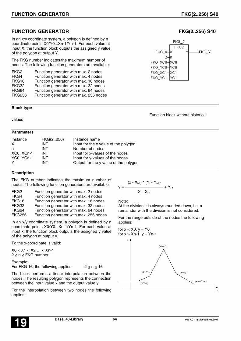
FUNCTION GENERATOR FKG(2..256) S40
Base_40-Library 64 907 AC 1131/Issued: 02.200119
FUNCTION GENERATOR FKG(2..256) S40
In an x/y coordinate system, a polygon is defined by ncoordinate points X0/Y0...Xn-1/Yn-1. For each value atinput X, the function block outputs the assigned y valueof the polygon at output Y.
The FKG number indicates the maximum number ofnodes. The following function generators are available:
FKG2 Function generator with max. 2 nodesFKG4 Function generator with max. 4 nodesFKG16 Function generator with max. 16 nodesFKG32 Function generator with max. 32 nodesFKG64 Function generator with max. 64 nodesFKG256 Function generator with max. 256 nodes
Block type
Function block without historicalvalues
Parameters
Instance FKG(2..256) Instance nameX INT Input for the x value of the polygonn INT Number of nodesXC0..XCn-1 INT Input for x-values of the nodesYC0..YCn-1 INT Input for y-values of the nodesY INT Output for the y value of the polygon
Description
The FKG number indicates the maximum number ofnodes. The following function generators are available:
FKG2 Function generator with max. 2 nodesFKG4 Function generator with max. 4 nodesFKG16 Function generator with max. 16 nodesFKG32 Function generator with max. 32 nodesFKG64 Function generator with max. 64 nodesFKG256 Function generator with max. 256 nodes
In an x/y coordinate system, a polygon is defined by ncoordinate points X0/Y0...Xn-1/Yn-1. For each value atinput x, the function block outputs the assigned y valueof the polygon at output y.
To the x-coordinate is valid:
X0 < X1 < X2 … < Xn-12 < n < FKG number
Example:For FKG 16, the following applies: 2 < n < 16
The block performs a linear interpolation between thenodes. The resulting polygon represents the connectionbetween the input value x and the output value y.
For the interpolation between two nodes the followingapplies:
(x - Xi-1) * (Yi - Yi-1)y = ––––––––––––––––– + Yi-1
Xi - Xi-1
Note:At the division it is always rounded down, i.e. aremainder with the division is not considered.
For the range outside of the nodes the followingapplies:
for x < X0, y = Y0for x > Xn-1, y = Yn-1
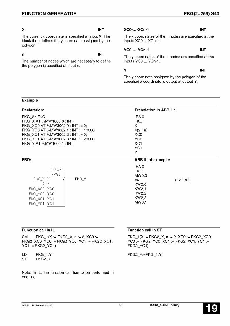
FUNCTION GENERATOR FKG(2..256) S40
907 AC 1131/Issued: 02.2001 65 Base_S40-Library 19
X INT
The current x coordinate is specified at input X. Theblock then defines the y coordinate assigned by thepolygon.
n INT
The number of nodes which are necessary to definethe polygon is specified at input n.
XC0-…-XCn-1 INT
The x coordinates of the n nodes are specified at theinputs XC0 ... XCn-1.
YC0-…-YCn-1 INT
The y coordinates of the n nodes are specified at theinputs YC0 ... YCn-1.
Y INT
The y coordinate assigned by the polygon of thespecified x coordinate is output at output Y.
Example
Declaration:
FKG_2 : FKG;FKG_X AT %MW1000.0 : INT;FKG_XC0 AT %MW3002.0 : INT := 0;FKG_YC0 AT %MW3002.1 : INT := 10000;FKG_XC1 AT %MW3002.2 : INT := 0;FKG_YC1 AT %MW3002.3 : INT := 20000;FKG_Y AT %MW1000.1 : INT;
Translation in ABB IL:
!BA 0FKGX#(2 * n)XC0YC0XC1YC1Y
FBD: ABB IL of example:
!BA 0FKGMW0,0#4 (* 2 * n *)KW2,0KW2,1KW2,2KW2,3MW0,1
Function call in IL
CAL FKG_1(X := FKG2_X, n := 2, XC0 :=FKG2_XC0, YC0 := FKG2_YC0, XC1 := FKG2_XC1,YC1 := FKG2_YC1)
LD FKG_1.YST FKG2_Y
Note: In IL, the function call has to be performed inone line.
Function call in ST
FKG_1(X := FKG2_X, n := 2, XC0 := FKG2_XC0,YC0 := FKG2_YC0, XC1 := FKG2_XC1, YC1 :=FKG2_YC1);
FKG2_Y:=FKG_1.Y;

FALLING EDGE DETECTION I_MINUS S40
Base_40-Library 66 907 AC 1131/Issued: 02.200119
FALLING EDGE DETECTION I_MINUS S40
A negative edge (TRUE/FALSE) at the input CLKgenerates a pulse at theoutput PULS wich has theduration of 1 PLC program cycle.
Block type
Function block without historical values
Parameters
Instance I_MINUS Instance nameCLK BOOL Input for TRUE/FALSE edgeQ BOOL Output for interrogation of the direct flag, operand M (not E, S)PULS BOOL Pulse output, operand M, A (not E, S)
Description
A negative edge (TRUE/FALSE) at the input CLKgenerates a pulse at theoutput PULS wich has theduration of 1 PLC program cycle
The output Q is needed for edge detection. This flagmust not be used again in the PLC program.
Duration of the pulse:From recognition of the TRUE/FALSE edge by theconnection element up to renewed processing of thisconnection element in the next program cycle

FALLING EDGE DETECTION I_MINUS S40
907 AC 1131/Issued: 02.2001 67 Base_S40-Library 19
Example
Declaration:
I_MINUS_1 : I_MINUS;I_MINUS_CLK AT %IX62.0 : BOOL;I_MINUS_Q AT %MX80.0 : BOOL;I_MINUS_PULS AT %MX0.0 : BOOL;
Translation in ABB IL:
! CLK=S Q!N CLK& Q=R Q= PULS
FBD: ABB IL of example:
! E62,0=S M80,0!N E62,0& M80,0=R M80,0=M0,0
Function call in IL
CAL I_MINUS_1(CLK := I_MINUS-CLK)
LD I_MINUS_1.QST I_MINUS_QLD I_MINUS_1.PULSST I_MINUS_PULS
Function call in ST
I_MINUS_1(CLK := I_MINUS_CLK, );
I_MINUS_Q := I_MINUS_1.Q;I_MINUS_PULS := I_MINUS_1.PULS;

RISING EDGE DETECTION I_PLUS S40
Base_40-Library 68 907 AC 1131/Issued: 02.200119
RISING EDGE DETECTION I_PLUS S40
A positive edge (FALSE/TRUE ) at the input CLKgenerates a pulse with the duration of one PLCprogram cycle at the PULS output.
Block type
Function block without historical values
Parameters
Instance I_PLUS Instance nameCLK BOOL Input for FALSE/TRUE edgeQ BOOL Output for interrogation of the direct flag, operand M (not E, S)PULS BOOL Pulse output, operand M, A (not E, S)
Description
A positive edge (FALSE/TRUE ) at the input CLKgenerates a pulse with the duration of one PLCprogram cycle at the PULS output.
The output Q is needed for edge detection. This flagmust not be used again in the PLC program
Duration of the pulse:From recognition of the FALSE/TRUE edge by theconnection element until renewed processing of thisconnection element in the next program cycle

RISING EDGE DETECTION I_PLUS S40
907 AC 1131/Issued: 02.2001 69 Base_S40-Library 19
Example
Declaration:
I_PLUS_1 : I_PLUS;I_PLUS_CLK AT %IX62.1 : BOOL;I_PLUS_Q AT %MX80.1 : BOOL;I_PLUS_PULS AT %MX0.1 : BOOL;
Translation in ABB IL:
!N CLK=R Q! CLK&N Q=S Q= PULS
FBD: ABB IL of example:
!N E62,1=R M80,1! E62,1&N M80,1=S M80,1= M0,1
Function call in IL
CAL I_PLUS_1(CLK := I_PLUS_CLK)
LD I_PLUS_1.QST I_PLUS_QLD I_PLUS_1.PULSST I_PLUS_PULS
Function call in ST
I_PLUS_1(CLK := I_PLUS_CLK, );
I_PLUS_Q := I_PLUS_1.Q;I_PLUS_PULS := I_PLUS_1.PULS;

READ BINARY VARIABLE, INDEXED IDLB S40
Base_40-Library 70 907 AC 1131/Issued: 02.200119
READ BINARY VARIABLE, INDEXED IDLB S40
The function block serves for the purpose of indexedreading of binary variables.
Block type
Function block without historical values
Parameters
Instance IDLB Instance nameFREI BOOL Block enabling
FREI = FALSE: Block is not processedFREI = TRUE: The value of the source variable is read andassigned to the target variable.
INDEX INT The index and the basic variable result in the source variableBASIS BOOL Basic address of the binary variableZIEL BOOL Target variable, operand M, A (not E, S)
Description
This function block serves the purpose of indexedreading of binary variables.
The source variable to be read is obtained fromindexing the basic variable.
The value of the source variable read is allocated to thetarget variable.
The group and channel numbers of the source flag(source variable) are determined from the basic flagand the index INDEX.
The source flag is :M (G_Basis + A) , (K_Basis + B)
where :
G_Basis : Group number of the basic flagK_Basis : Channel number of the basic flag
Formula :
INDEX ---------- = A Remainder B 16
Group No. of the source flag :Group No. of the basic flag + A
Channel No. of the source flag :Channel No. of the basic flag + B
Example :
Basic variable : M00,00 AT %MX000.00
INDEX = 10
-> A = 10 : 16 -> A = 0, Remainder B = 10
->Source variable :%MX(000+A).(00+B) =%MX(000+0).(00+10) =%MX000.10
Further examples :
Basic variable INDEX Source variable
%MX000.00 0 %MX000.00
%MX000.00 2 %MX000.02
%MX000.00 16 %MX001.00
%MX000.02 18 %MX001.04
FREI BOOL
Enable block
FREI = FALSE -> Block is not processed
FREI = TRUE -> The value of the source variable isread and allocated to the targetvariable ZIEL.

READ BINARY VARIABLE, INDEXED IDLB S40
907 AC 1131/Issued: 02.2001 71 Base_S40-Library 19
INDEX INT
The index value is specified at the input INDX. Thesource variable (see above for a calculation) resultsfrom the index and the basic variable.
Value range : -16383 < INDEX < +16383
BASIS BOOL
The basic variable is specified at the input BASIS. Thesource variable (see above for a calculation) resultsfrom the index and the basic variable.
ZIEL BOOL
The target variable is specified at the output ZIEL. Thevalue of the selected source variable is allocated to thetarget variable ZIEL.
Example
Declaration:
IDLB_1 : IDLB;IDLB_FREI AT %MX0.0 : BOOL;IDLB_INDEX AT %MW1000.0 : INT;IDLB_BASIS AT %MX20.0 : BOOL;IDLB_ZIEL AT %MX0.1 : BOOL;
Translation in ABB IL:
!BA 0IDLBFREIINDEXBASISZIEL
FBD: ABB IL of example:
!BA 0IDLBM0,0MW0,0M20,0M0,1
Function call in IL
CAL IDLB_1(FREI := IDLB_FREI,INDEX := IDLB_INDEX,BASIS := IDLB_BASIS)
LD IDLB_1.ZIELST IDLB_ZIEL
Note: In IL, the function call has to be performed inone line.
Function call in ST
IDLB_1 (FREI := IDLB_FREI,INDEX := IDLB_INDEX,BASIS := IDLB_BASIS);
IDLB_ZIEL:=IDLB_1.ZIEL;

READ WORD VARIABLE, INDEXED IDLM S40
Base_40-Library 72 907 AC 1131/Issued: 02.200119
READ WORD VARIABLE, INDEXED IDLM S40
The function block serves for the purpose of indexedreading of word variables.
Block type
Function block without historical values
Parameters
Instance IDLm Instance nameFREI BOOL Block enabling
FREI = FALSE: Block is not processedFREI = TRUE: The value of the source variable is read and assigned tothe target variable.
INDEX INT The index and the basic variable result in the source variableBASIS INT Basic variableZIEL INT Target variable
Description
The function block serves for the purpose of indexedreading of word variables.
The source variable to be read is obtained fromindexing the basic variable. The value of the sourcevariable read is assigned to the target variable.
The inputs and outputs can neither be duplicated norinverted nor negated.
The group and channel numbers of the source flag(source variable) are determined from the basic flagand the index.
The source flag is :MW (G_Basis + A) , (K_Basis + B)
where :
G_Basis : Group number of the basic flagK_Basis : Channel number of the basic flag
Formula :
INDEX ---------- = A Remainder B 16
Group No. of the source flag :Group No. of the basic flag + A
Channel No. of the source flag :Channel No. of the basic flag + B
Example :
Basic variable : MW00,00 AT %MW1000.00
INDEX = 10
-> A = 10 : 16 -> A = 0, Remainder B = 10
-> Source variable :%MW(1000+A).(00+B) =%MW(1000+0).(00+10) =%MW1000.10
Further examples :
Basic variable INDEX Source variable
%MW1000.00 0 %MW1000.00
%MW1000.00 2 %MW1000.02
%MW100.00 16 %MW1001.00
%MW1000.02 18 %MW1001.04

READ WORD VARIABLE, INDEXED IDLM S40
907 AC 1131/Issued: 02.2001 73 Base_S40-Library 19
FREI BOOL
Block enabling
FREI = FALSE→ Block is not processed
FREI = TRUE→ The value of the source variable is read andassigned to the target variable ZIEL.
INDEX INT
The index value is specified at input INDEX. Thesource variable results from the index and the basicvariable.
Value range: -32767 < INDEX < +32767
If INDEX is not within this range, the function block isnot processed.
BASIS INT
The basic variable is specified at input BASIS. Thesource variable results from the index and the basicvariable.
ZIEL INT
The target variable is specified at output ZIEL. Thevalue of the selected source variable is assigned to thetarget variable ZIEL.
Example
Declaration:
IDLm_1 : IDLm;IDLm_FREI AT %MX0.0 : BOOL;IDLm_INDEX AT %MW1002.0 : INT;IDLm_BASIS AT %MW1020.0 : INT;IDLm_ZIEL AT %MW1002.1 : INT;
Translation in ABB IL:
!BA 0IDLFREIINDEXBASISZIEL
FBD: ABB IL of example:
!BA 0IDLM0,0MW2,0MW20,0MW2,1
Function call in IL
CAL IDLM_1(FREI := IDLM_FREI,INDEX := IDLM_INDEX,BASIS := IDLM_BASIS)
LD IDLM_1.ZIELST IDLM_ZIEL
Note: In IL, the function call has to be performed inone line.
Function call in ST
IDLM_1 (FREI := IDLM_FREI,INDEX := IDLM_INDEX,BASIS := IDLM_BASIS);
IDLM_ZIEL := IDLM_1.ZIEL;

WRITE BINARY VARIABLE, INDEXED IDSB S40
Base_40-Library 74 907 AC 1131/Issued: 02.200119
WRITE BINARY VARIABLE, INDEXED IDSB S40
The function block serves for the purpose of indexedwriting of binary variables.
Block type
Function block without historical values
Parameters
Instance IDSB Instance nameFREI BOOL Block enabling
FREI = FALSE: Block is not processedFREI = TRUE: The value of the source variable is read andassigned to the target variable.
QUELL BOOL Source variableINDEX INT The current target variable results from the index and the basic
variableBASIS BOOL Basic variable, operands M, A (not E, S)
Description
The function block serves for the purpose of indexedwriting of binary variables.When the block is enabled, the value of the sourcevariable is read and assigned to the target variable.The target variable is defined by indexing the basicvariable.
The inputs and outputs can neither be duplicated norinverted nor negated.
The group and channel numbers of the target flag(target variable) are determined on the basic flag andthe index INDEX.
The target flag is called:M (G_Basis + A) , (K_Basis + B)
where :
G_Basis : Group number of the basic flagK_Basis : Channel number of the basic flag
Formula :
INDEX ---------- = A Remainder B 16
Group No. of the target flag :Group No. of the basic flag + A
Channel No. of the target flag :Channel No. of the basic flag + B
Example :
Basic variable : M00,00 AT %MX000.00
INDEX = 10
-> A = 10 : 16 -> A = 0, Remainder B = 10
->Target variable :%MX(000+A).(00+B) =%MX(000+0).(00+10) =%MX000.10
Further examples :
Basic variable INDEX Target variable
%MX000.00 0 %MX000.00
%MX000.00 2 %MX000.02
%MX000.00 16 %MX001.00
%MX000.02 18 %MX001.04

WRITE BINARY VARIABLE, INDEXED IDSB S40
907 AC 1131/Issued: 02.2001 75 Base_S40-Library 19
FREI BOOL
Block enablingFREI = FALSE → Block is not processed
FREI = TRUE → The value of the source variable isread and assigned to the targetvariable.
QUELL BOOL
The source variable is specified at input QUELL. Thevalue of this variable is read and assigned to the targetvariable.
INDEX INT
The index value is specified at input INDEX. Thesource variable results from the index and the basicvariable.Value range: -16383 < INDEX < +16383If INDEX is not within this range, the function block isnot processed.
BASIS BOOL
The basic variable is specified at the output BASIS.
The target variable (see above for a calculation) resultsfrom the index INDEX and the basic variable.
Example
Declaration:
IDSB_1 : IDSB;IDSB_FREI AT %MX0.0 : BOOL;IDSB_QUELL AT %MX1.0 : INT;IDSB_INDEX AT %MW1001.1 : INT;IDSB_BASIS AT %MX20.0 : INT;
Translation in ABB IL:
!BA 0IDSBFREIQUELLINDEXBASIS
FBD: ABB IL of example:
!BA 0IDSBM0,0M1,0MW1,1M20,0
Function call in IL
CAL IDSB_1(FREI := IDSB_FREI,QUELL := IDSB_QUELL,INDEX := IDSB_INDEX)
LD IDSB_1.BASISST IDSB_BASIS
Note: In IL, the function call has to be performed inone line.
Function call in ST
IDSB_1 (FREI := IDSB_FREI,QUELL := IDSB_QUELL,INDEX := IDSB_INDEX);
IDSB_BASIS := IDSB_1.BASIS;

WRITE WORD VARIABLE, INDEXED IDSM S40
Base_40-Library 76 907 AC 1131/Issued: 02.200119
WRITE WORD VARIABLE, INDEXED IDSM S40
The function block serves for the purpose of indexedwriting of word variables.
Block type
Function block without historical values
Parameters
Instance IDSm Instance nameFREI BOOL Block enabling
FREI = FALSE: Block is not processedFREI = TRUE: The value of the source variable is read and assignedto the target variable.
QUELL INT Source variableINDEX INT The index and the basic variable result in the source variableBASIS INT Basic variable
Description
The function block serves for the purpose of indexedwriting of word variables.When the block is enabled, the value of the sourcevariable is read and assigned to the target variable.The target variable is defined by indexing the basicvariable.
The inputs and outputs can neither be duplicated norinverted nor negated.
The group and channel numbers of the target flag(target variable) are determined on the basic flag andthe index INDEX.
The target flag is called:MW (G_Basis + A) , (K_Basis + B)
where :
G_Basis : Group number of the basic flagK_Basis : Channel number of the basic flag
Formula :
INDEX ---------- = A Remainder B 16
Group No. of the target flag :Group No. of the basic flag + A
Channel No. of the target flag :Channel No. of the basic flag + B
Example :
Basic variable : MW00,00 AT %MW1000.00
INDEX = 10
-> A = 10 : 16 -> A = 0, Remainder B = 10
->Target variable :%MW(1000+A).(00+B) =%MW(1000+0).(00+10) =%MW1000.10
Further examples :
Basic variable INDEX Target variable
%MW1000.00 0 %MW1000.00
%MW1000.00 2 %MW1000.02
%MW1000.00 16 %MW1001.00
%MW1000.02 18 %MW1001.04

WRITE WORD VARIABLE, INDEXED IDSM S40
907 AC 1131/Issued: 02.2001 77 Base_S40-Library 19
FREI BOOL
Block enablingFREI = FALSE → Block is not processed
FREI = TRUE → The value of the source variable isread and assigned to the targetvariable.
QUELL INT
The source variable is specified at input QUELL. Thevalue of this variable is read and assigned to the targetvariable.
INDEX INT
The index value is specified at input INDEX. Thesource variable results from the index and the basicvariable.Value range: -32767 < INDEX < +32767If INDEX is not within this range, the function block isnot processed.
BASIS INT
The basic variable is specified at output BASIS. Thetarget variable (see above for a calculation) resultsfrom the index INDEX and the basic variable.
Example
Declaration:
IDSm_1 : IDSmIDSm_FREI AT %MX0.0 : BOOL;IDSm_QUELL AT %MW1020.0 : INT;IDSm_INDEX AT %MW1002.1 : INT;IDSm_BASIS AT %MW1002.2 : INT;
Translation in ABB IL:
!BA 0IDSmFREIQUELLINDEXBASIS
FBD: ABB IL of example:
!BA 0IDSmM0,0MW20,0MW2,1MW2,2
Function call in IL
CAL IDSM_1(FREI := IDSM_FREI,QUELL := IDSM_QUELL,INDEX := IDSM_INDEX)
LD IDSM_1.BASISST IDSM_BASIS
Note: In IL, the function call has to be performed inone line.
Function call in ST
IDSM_1 ( FREI := IDSM_FREI,QUELL := IDSM_QUELL,INDEX := IDSM_INDEX);
IDSM_BASIS := IDSM_1.BASIS;

LIST ALLOCATOR LIZU(8..256) S40
Base_40-Library 78 907 AC 1131/Issued: 02.200119
LIST ALLOCATOR LIZU(8..256) S40
The function block has a list of word data at its inputs.With a list pointer, it selects a value out of this list andapplies it at its output.
The LIZU number indicates the maximum number ofword data. The following list allocators are available:
LIZU8 List allocator for max. 8 word dataLIZU16 List allocator for max. 16 word dataLIZU32 List allocator for max. 32 word dataLIZU64 List allocator for max. 64 word dataLIZU256 List allocator for max. 256 word data
Block type
Function block without historical values
Parameters
Instance LIZU(8..256) Instance nameZEIG INT Pointer to the list of word dataE0..En-1 INT List of direct constantsA_E BOOL 0 < ZEIG < n, i.e. pointer in the valid range, operands M, A (not E, S)A INT Selected word value
Description
The function block has a list of word data at its inputs.With a list pointer, it selects a value out of this list andapplies it at its output.
The inputs and outputs cannot be inverted andduplicated.
ZEIG INT
The pointer to the word value to be selected from thelist is specified at input ZEIG.
The following allocation applies:
ZEIG = 0 → Word value at E0ZEIG = 1 → Word value at E1: : :ZEIG = n-1 → Word value at En-1
The value at input ZEIG is subjected to a validitycheck. The result of this range check is signalized atoutput A_E.
Allowed range:
0 < ZEIG < n-1
With n: Number of the inputs E0..En-1.
No allocation to output A takes place if the value atinput ZEIG is outside the allowed range.
E0 .. En-1 INT
The word values out of which one is selected with thevalue at input ZEIG and assigned to output A arespecified at the inputs E0 ... En-1.
A_E BOOL
Output A_E indicates whether the value of the listpointer (input ZEIG) is within the allowed range.
Allowed range:
0 < ZEIG < n-1
With n: Number of the inputs E0..En-1.
The following applies:
ZEIG in the allowed range → A_E = TRUEZEIG in the forbidden range → A_E = FALSE
If the list pointer has a forbidden value, no allocationof a value to output A takes place because no wordvalue can be selected. In this case, output A is notupdated.
A INT
The value of the selected word value is assigned tothe operand at output A.

LIST ALLOCATOR LIZU(8..256) S40
907 AC 1131/Issued: 02.2001 79 Base_S40-Library 19
Example
Declaration:
LIZU8_1 : LIZU8;LIZU_ZEIG AT %MW1000.0: INT;LIZU_A_E AT %MX0.0 : BOOL;LIZU_A AT %MW1000.1 : INT;
Translation in ABB IL:
!BA 0LIZUZEIG#n#E0#E1#E2#E3#E4#E5#E6#E7A_EA
FBD: ABB IL of example:
!BA 0LIZUMW0,0#8#1#2#3#4#5#6#7#8M0,0MW0,1
Function call in IL
CAL LIZU_8(ZEIG := LIZU8_ZEIG,n := 8,E0 := 1,E1 := 2,E2 := 3,E3 := 4,E4 := 5,E5 := 6,E6 := 7,E7 := 8)
LD LIZU8_1.A_EST LIZU_A_ELD LIZU8_1.AST LIZU8_A
Note: In IL, the function call has to be performed inone line.
Function call in ST
LIZU_8 ZEIG := LIZU8_ZEIG,n := 8,E0 := 1,E1 := 2,E2 := 3,E3 := 4,E4 := 5,E5 := 6,E6 := 7,E7 := 8);
LIZU8_A_E := LIZU8_1.A_E;LIZU8_A := LIZU8_1.A;

MONOSTABLE ELEMENT »ABORT« MOA S40
Base_40-Library 80 907 AC 1131/Issued: 02.200119
MONOSTABLE ELEMENT »ABORT« MOA S40
A FALSE/TRUE edge at input E causes aFALSE/TRUE edge at output A. If input E remains atTRUE level, a TRUE/FALSE edge is applied at outputA after the duration T has elapsed.
Output A is also immediately set back to FALSE level ifinput E returns to FALSE level before the time period Thas expired.
Maximum time offset at the output: < 1 cycle time
Block type
Function block with historical values
Parameters
Instance MOA Instance nameE BOOL Input signalT TIME Pulse lengthA BOOL Output signal, operands M, A (not E, S)
Description
A FALSE/TRUE edge at input E causes aFALSE/TRUE edge at output A. If input E remains atTRUE level, a TRUE/FALSE edge is applied atoutput A after the duration T has elapsed.
Output A is also immediately set back to FALSE levelif input E returns to FALSE level before the timeperiod T has expired.
Valid time range: 5 ms .. 24,8 days.
Maximum time offset at the output: < 1 cycle time
Reasonable range for T: > 1 cycle time
The inputs and the output can neither be duplicatednor inverted.
General behavior
� Started timers are processed by the PLC operatingsystem and are therefore completely independent ofprocessing of the PLC program. An appropriatemessage of the operating system is not issued to theaffiliated timer block in the PLC program until thetimer has elapsed.
� Processing of a timer in the PLC operating systemis influenced by the following commands. All runningtimers are stopped and initialized when one of thefollowing actions occurs:
� Abort PLC program� RUN/STOP switch from RUN -> STOP� Warm or cold start

MONOSTABLE ELEMENT »ABORT« MOA S40
907 AC 1131/Issued: 02.2001 81 Base_S40-Library 19
Example
Declaration:
MOA_1 : MOA;MOA_E AT %MX0.0 : BOOL;MOA_T %MD4001.0 : TIME := t#1m; (*60000 ms*)MOA_A AT %MX0.1 : BOOL;
Translation in ABB IL:
!BA 0MOAETA
FBD: ABB IL of example:
!BA 0MOAM0,0KD1,0 ; 60000M0,1
Function call in IL
CAL MOA_1(E := MOA_E,T := MOA_T)
LD MOA_1.AST MOA_A
Note: In IL, the function call has to be performed inone line.
Function call in ST
MOA_1 (E := MOA_E,T := MOA_T);
MOA_A := MOA_1.A;
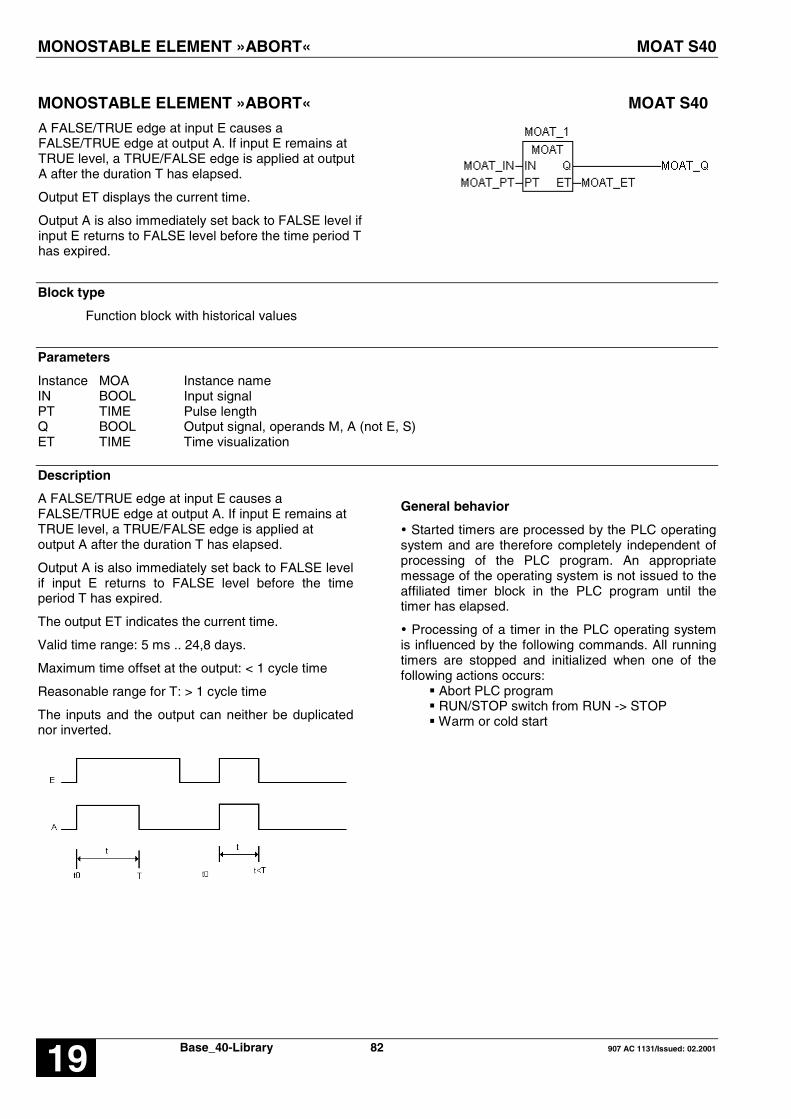
MONOSTABLE ELEMENT »ABORT« MOAT S40
Base_40-Library 82 907 AC 1131/Issued: 02.200119
MONOSTABLE ELEMENT »ABORT« MOAT S40
A FALSE/TRUE edge at input E causes aFALSE/TRUE edge at output A. If input E remains atTRUE level, a TRUE/FALSE edge is applied at outputA after the duration T has elapsed.
Output ET displays the current time.
Output A is also immediately set back to FALSE level ifinput E returns to FALSE level before the time period Thas expired.
Block type
Function block with historical values
Parameters
Instance MOA Instance nameIN BOOL Input signalPT TIME Pulse lengthQ BOOL Output signal, operands M, A (not E, S)ET TIME Time visualization
Description
A FALSE/TRUE edge at input E causes aFALSE/TRUE edge at output A. If input E remains atTRUE level, a TRUE/FALSE edge is applied atoutput A after the duration T has elapsed.
Output A is also immediately set back to FALSE levelif input E returns to FALSE level before the timeperiod T has expired.
The output ET indicates the current time.
Valid time range: 5 ms .. 24,8 days.
Maximum time offset at the output: < 1 cycle time
Reasonable range for T: > 1 cycle time
The inputs and the output can neither be duplicatednor inverted.
General behavior
� Started timers are processed by the PLC operatingsystem and are therefore completely independent ofprocessing of the PLC program. An appropriatemessage of the operating system is not issued to theaffiliated timer block in the PLC program until thetimer has elapsed.
� Processing of a timer in the PLC operating systemis influenced by the following commands. All runningtimers are stopped and initialized when one of thefollowing actions occurs:
� Abort PLC program� RUN/STOP switch from RUN -> STOP� Warm or cold start

MONOSTABLE ELEMENT »ABORT« MOAT S40
907 AC 1131/Issued: 02.2001 83 Base_S40-Library 19
Example
Declaration:
MOAT_1 : MOATMOAT_IN AT %MX0.0 : BOOL;MOAT_PT AT %MD4002.0 : TIME := t#2s500ms; (*2500 ms*)MOAT_Q AT %MX0.1 : BOOL;MOAT_ET AT %MD2002.0 : TIME;
Translation in ABB IL:
!BA 0MOATINPTQET
FBD: ABB IL of example:
!BA 0MOATM0,0KD2,0 ; 2500M0,1MD2,0
Function call in IL
CAL MOAT_1(E := MOAT_E,T := MOAT_T)
LD MOAT_1.AST MOAT_A
Note: In IL, the function call has to be performed inone line.
Function call in ST
MOAT_1 (E := MOAT_E,T := MOAT_T);
MOAT_A := MOAT_1.A;

OPERATION MODE MODBUS MASTER MODMASTB/W S40
Base_40-Library 84 907 AC 1131/Issued: 02.200119
OPERATION MODE MODBUS MASTER MODMASTB/W S40
MODBUS master communication:
MODBUSB COM1 by defaultand DATA is a BOOL
MODBUSW COM1 by defaultand DATA is an INT
MODMASTB COM1 or COM2and DATA is a BOOL
MODMASTW COM1 or COM2and DATA is an INT
Block type
Function block with historical values
Parameters
Instance MODBUS B/WMODMAST B/W
Instance name
EN BOOL Enabling of the block processingCOM INT Interface identifier (COM1, COM2)SLAVE INT Slave address (1...255)FCT INT Function codeTIMEOUT INT Telegram timeout in millisecondsADDR INT Operand/register address in the slaveNB INT Number of dataDATA BOOL / INT Data to send to the slave or to write with the data received
from a slave MODBUSRDY BOOL Ready message, communication in progress, operands M, AERR BOOL Error message, operands M, A (not E, S)ERNO INT Error identifier
Description
MODBUS master communication function block
The central unit is a master on a MODBUS networkand can communicate with other products withMODBUS protocol.The function MODBUS MASTER in the central unit isvalided by :- system constant KW 00,06 / %MW1000.6 = 100- and connection between pins 7 and 6 on theconnector of the serial interface
Several function blocks MODBUS/MODMAST can beused in one user program.
The MODBUS protocol is a master/slave protocol.The master sends a frame to a slave and waits forthe answer (a timeout is defined). Binary or numericdata can be read or written in a slave.
The area of data in the master is chosen by theaddress of the first variable. The size of area isnecessary for sending or receiving. Reading orwriting data are done automatically from these areas.
EN BOOL
A rising edge at the FREI input leads to an output ofa request to a MODBUS slave, provided that theblock is ready to do this (RDY = TRUE).If a rising edge appears at the FREI input althoughthe RDY output is equal to FALSE, i.e. the block isnot ready for a new MODBUS communication, therising edge will be ignored. Therefore, no newMODBUS communication can be started as long asthe RDY output is FALSE.
OPERATION MODE MODBUS MASTER MODMASTB/W S40
907 AC 1131/Issued: 02.2001 85 Base_S40-Library 19
COM INT
At input COM the MODBUS interface number isspecified.COM = 1: COM1 (PLC)COM = 2: COM2 (PLC)
SLAV INT
Address of the slave which receives the request.Value : 0 < ADDR < 255In case of address 0 (ADDR = 0), all slaves on theMODBUS network will read the frame.
FCT INT
The function depends on the type of parameters andif it is reading or writing.
Value : 1 (01H): reading n bits2 (02H): reading n bits3 (03H): reading n words4 (04H): reading n words5 (05H): writing one bit6 (06H): writing one word7 (07H): fast reading of 8 bits8 (08H): Diagnosis/initialization
15 (0FH): writing n bits16 (10H): writing n words
The other function codes are not supported by thecentral units series 40..50. In case of a wrongfunction code, an error 1 is generated in the wordERNO.
TIME INT
Timeout for the communication (maximum time for ananswer of the MODBUS slave).
The value is given in milliseconds.
Cycle time (KD00,00 / %MD4000.0) < TIME < 32767
In case of a timeout, the output ERN provides thevalue of 9.
ADDR INT
Address of data in the slave memory to read or write.
NB INT
Number of data to read or write in the slave.
This number defines also the size of the data area inthe master to send to the slave or to receive from theslave.
DATA INT, BOOL
INT: MODBUSW or MODMASTWBOOL:
DATA defines the first variable of the data area in themaster. The size of this area depends on the NBparameter.
Different cases are possible according to the functioncode and the operand :
Reading :ADDR DATA ResultINT INT IdemBOOL BOOL IdemBOOL INT Same as the function block
PACKINT BOOL The first bit of the word is ranged
in the first bit of the group number
Example : data = %MX00.07 :The first bit of the read word will be writtenin %MX 00.00.
Writing :ADDR DATA ResultINT INT IdemBOOL BOOL IdemBOOL INT Same as the function block PACKINT BOOL Same as the function block
UNPACK
RDY BOOL
The output RDY (ready) indicates whether aMODBUS communication is in progress or not. Aslong as a communication is in progress, the outputRDY is equal to FALSE. The function block can onlybe used if RDY = TRUE.
ERR BOOL
The output ERR indicates an error occurred duringcommunication. The word output ERN indicates thedetails of the error.
If ERR = 1 -> error,ERR = 0 -> no error or communication in
progress.
The error is clear after one cycle time.
ERNO INT
Details of error :0 : no error1 : unknown function code2 : address error3 : data error9 : timeout
10 : checksum errorThe error is clear after one cycle time.

OPERATION MODE MODBUS MASTER MODMASTB/W S40
Base_40-Library 86 907 AC 1131/Issued: 02.200119
Operands (symbolic) Operands(IEC)
MODBUS address (HEX) Operand description
E000_00:
E061_15
%IX000.00:
%IX061.15
0000HEX:
03DFHEX
Binary inputs, CS31 bus
E062_00:
E068_15
%IX062.00:
%IX068.15
03E0HEX:
044FHEX
Binary inputs, local
A000_00:
A061_15
%QX000.00:
%QX061.15
1000HEX:
13DFHEX
Binary outputs, CS31 bus
A062_00:
A068_15
%QX062.00:
%QX068.15
13E0HEX:
144FHEX
Binary outputs, local
M000_00:
M099_15
%MX0000.00:
%MX0099.15
2000HEX:
263FHEX
Binary flags
M230_00:
M254_15
%MX0000.00:
%MX0254.15
2000HEX:
2FEFHEX
Binary flags
M255_00:
M255_15
%MX0255.00:
%MX0255.15
2FF0HEX:
2FFFHEX
Binary flags (system)
S000_00:
S125_15
%MX5000.00:
%MX5125.15
3000HEX:
37DFHEX
Steps
EW000_00:
EW061_15
%IW1000.00:
%IW1061.15
0000HEX:
03DFHEX
Analog inputs, CS31 bus
EW062_00:
EW068_15
%IW1062.00:
%IW1068.15
03E0HEX:
044FHEX
Analog inputs, local
AW000_00:
AW061_15
%QW1000.00:
%QW1061.15
1000HEX:
13DFHEX
Analog outputs, CS31 bus
AW062_00:
AW068_15
%QW1062.00:
%QW1068.15
13E0HEX:
144FHEX
Analog outputs, local

OPERATION MODE MODBUS MASTER MODMASTB/W S40
907 AC 1131/Issued: 02.2001 87 Base_S40-Library 19
Operands (symbolic) Operands(IEC)
MODBUS address (HEX) Operand description
MW000_00:
MW099_15
%MW1000.00:
%MW1099.15
2000HEX:
263FHEX
Word flags
MW230_00:
MW253_15
%MW1230.00:
%MW1253.15
2E60HEX:
2FCFHEX
Word flags
MW254_00:
MW255_15
%MW1254.00:
%MW1255.15
2FD0HEX:
2FFFHEX
Word flags (error message)
KW000_00:
KW000_15
%MW3000.00:
%MW3000.15
3000HEX:
300FHEX
Word constants (system)
KW001_00:
KW031_15
%MW3001.00:
%MW3031.15
3010HEX:
31FFHEX
Word constants
MD000_00:
MD007_15
%MD2000.00:
%MD2007.15
4000HEX:
40FEHEX
Double word flags
KD000_00:
KD000_15
%MD4000.00:
%MD4000.15
5000HEX:
501EHEX
Double word constants
KD001_00:
KD007_15
%MD4000.00:
%MD4007.15
5020HEX:
50FEHEX
Double word constants

OPERATION MODE MODBUS MASTER MODMASTB/W S40
Base_40-Library 88 907 AC 1131/Issued: 02.200119
Example 1: MODBUSB – MODBUS master only for COM1 and BOOL - data
Declaration:
MOD_1: MODBUSB;MOD_EN AT %MX13.0: BOOL;MOD_SLAV AT %MW3002.1: INT := 10;MOD_FCT AT %MW3002.2: INT := 3;MOD_TIMEOUT AT %MW3002.3: INT := 5000;MOD_ADDR AT %MW3002.4: INT := 16#2000; (*8192*)MOD_NB AT %MW3002.5: INT := 16;MOD_DATA_B AT %MX40.0: BOOL;MOD_RDY AT %MX30.0: BOOL;MOD_ERR AT %MX30.1: BOOL;MOD_ERNO AT %MW1039.0: INT;
Translation in ABB IL:
!BA 0CALLUPEN#H0300#H0000#H0000#00009SLAVFCTTIMEOUTADDRNBDATARDYERRERNO
FBD: ABB IL of example:
!BA 0CALLUPM0,0#H0300#H0000#H0000#00009KW2,1 ; 10KW2,2 ; 3KW2,3 ; 5000KW2,4 ; 8192KW2,5 ; 16M40,0M30,0M30,1MW39,0
Function call in ILCAL MOD_1(EN := MOD_EN,
SLAV := MOD_SLAV,FCT := MOD_FCT,TIMEOUT := MOD_TIMEOUT,ADDR := MOD_ADDR,NB := MOD_NB,DATA := MOD_DATA_B)
LD MOD_1.RDYST MOD_RDYLD MOD_1.ERRST MOD_ERRLD MOD_1.ERNOST MOD_ERNO
Function call in STMOD_1 (EN := MOD_EN,
SLAV := MOD_SLAV,FCT := MOD_FCT,TIMEOUT := MOD_TIMEOUT,ADDR := MOD_ADDR,NB := MOD_NB,DATA := MOD_DATA_B)
MOD_RDY := MOD_1.RDY;MOD_ERR := MOD_1.ERR;MOD_ERNO := MOD_1.ERNO;

OPERATION MODE MODBUS MASTER MODMASTB/W S40
907 AC 1131/Issued: 02.2001 89 Base_S40-Library 19
Example 2: MODBUSW – MODBUS master only for COM1 and INT - data
Declaration:
MOD_1: MODBUSW;MOD_EN AT %MX13.0: BOOL;MOD_SLAV AT %MW3002.1: INT := 10;MOD_FCT AT %MW3002.2: INT := 3;MOD_TIMEOUT AT %MW3002.3: INT := 5000;MOD_ADDR AT %MW3002.4: INT := 16#2000; (*8192*)MOD_NB AT %MW3002.5: INT := 16;MOD_DATA AT %MW1030.0: INT;MOD_RDY AT %MX30.0: BOOL;MOD_ERR AT %MX30.1: BOOL;MOD_ERNO AT %MW1039.0: INT;
Translation in ABB IL:
!BA 0CALLUPEN#H0300#H0000#H0000#00009SLAVFCTTIMEOUTADDRNBDATARDYERRERNO
FBD: ABB IL of example:
!BA 0CALLUPM0,0#H0300#H0000#H0000#00009KW2,1 ; 10KW2,2 ; 3KW2,3 ; 5000KW2,4 ; 8192KW2,5 ; 16MW30,0M30,0M30,1MW39,0
Function call in ILCAL MOD_1(EN := MOD_EN,
SLAV := MOD_SLAV,FCT := MOD_FCT,TIMEOUT := MOD_TIMEOUT,ADDR := MOD_ADDR,NB := MOD_NB,DATA := MOD_DATA)
LD MOD_1.RDYST MOD_RDYLD MOD_1.ERRST MOD_ERRLD MOD_1.ERNOST MOD_ERNO
Function call in STMOD_1 (EN := MOD_EN,
SLAV := MOD_SLAV,FCT := MOD_FCT,TIMEOUT := MOD_TIMEOUT,ADDR := MOD_ADDR,NB := MOD_NB,DATA := MOD_DATA)
MOD_RDY := MOD_1.RDY;MOD_ERR := MOD_1.ERR;MOD_ERNO := MOD_1.ERNO;

OPERATION MODE MODBUS MASTER MODMASTB/W S40
Base_40-Library 90 907 AC 1131/Issued: 02.200119
Example 3: MODMASTB – MODBUS master for COM1/COM2 and BOOL - data
Declaration:
MOD_1: MODMASTB;MOD_EN AT %MX13.0: BOOL;MOD_COM AT %MW3002.0: INT := 1;MOD_SLAV AT %MW3002.1: INT := 10;MOD_FCT AT %MW3002.2: INT := 3;MOD_TIMEOUT AT %MW3002.3: INT := 5000;MOD_ADDR AT %MW3002.4: INT := 16#2000; (*8192*)MOD_NB AT %MW3002.5: INT := 16;MOD_DATA_B AT %MX40.0: INT;MOD_RDY AT %MX30.0: BOOL;MOD_ERR AT %MX30.1: BOOL;MOD_ERNO AT %MW1039.0: INT;
Translation in ABB IL:
!BA 0CALLUPEN#H0306#H0000#H0000#00010COMSLAVFCTTIMEOUTADDRNBDATARDYERRERNO
FBD: ABB IL of example:
!BA 0CALLUPM0,0#H0306#H0000#H0000#00010KW2,0 ; 1KW2,1 ; 10KW2,2 ; 3KW2,3 ; 5000KW2,4 ; 8192KW2,5 ; 16M40,0M30,0M30,1MW39,0
Function call in ILCAL MOD_1(EN := MOD_EN,
COM := MOD_COM,SLAV := MOD_SLAV,FCT := MOD_FCT,TIMEOUT := MOD_TIMEOUT,ADDR := MOD_ADDR,NB := MOD_NB,DATA := MOD_DATA_B)
LD MOD_1.RDYST MOD_RDYLD MOD_1.ERRST MOD_ERRLD MOD_1.ERNOST MOD_ERNO
Function call in STMOD_1 (EN := MOD_EN,
COM := MOD_COM,SLAV := MOD_SLAV,FCT := MOD_FCT,TIMEOUT := MOD_TIMEOUT,ADDR := MOD_ADDR,NB := MOD_NB,DATA := MOD_DATA_B)
MOD_RDY := MOD_1.RDY;MOD_ERR := MOD_1.ERR;MOD_ERNO := MOD_1.ERNO;

OPERATION MODE MODBUS MASTER MODMASTB/W S40
907 AC 1131/Issued: 02.2001 91 Base_S40-Library 19
Example 4: MODMASTW – MODBUS master for COM1/COM2 and INT - data
Declaration:
MOD_1: MODMASTW;MOD_EN AT %MX13.0: BOOL;MOD_COM AT %MW3002.0: INT := 1;MOD_SLAV AT %MW3002.1: INT := 10;MOD_FCT AT %MW3002.2: INT := 3;MOD_TIMEOUT AT %MW3002.3: INT := 5000;MOD_ADDR AT %MW3002.4: INT := 16#2000; (*8192*)MOD_NB AT %MW3002.5: INT := 16;MOD_DATA AT %MW1030.0: INT;MOD_RDY AT %MX30.0: BOOL;MOD_ERR AT %MX30.1: BOOL;MOD_ERNO AT %MW1039.0: INT;
Translation in ABB IL:
!BA 0CALLUPEN#H0306#H0000#H0000#00010COMSLAVFCTTIMEOUTADDRNBDATARDYERRERNO
FBD: ABB IL of example:
!BA 0CALLUPM0,0#H0306#H0000#H0000#00010KW2,0 ; 1KW2,1 ; 10KW2,2 ; 3KW2,3 ; 5000KW2,4 ; 8192KW2,5 ; 16MW30,0M30,0M30,1MW39,0
Function call in ILCAL MOD_1(EN := MOD_EN,
COM := MOD_COM,SLAV := MOD_SLAV,FCT := MOD_FCT,TIMEOUT := MOD_TIMEOUT,ADDR := MOD_ADDR,NB := MOD_NB,DATA := MOD_DATA)
LD MOD_1.RDYST MOD_RDYLD MOD_1.ERRST MOD_ERRLD MOD_1.ERNOST MOD_ERNO
Function call in STMOD_1 (EN := MOD_EN,
COM := MOD_COM,SLAV := MOD_SLAV,FCT := MOD_FCT,TIMEOUT := MOD_TIMEOUT,ADDR := MOD_ADDR,NB := MOD_NB,DATA := MOD_DATA)
MOD_RDY := MOD_1.RDY;MOD_ERR := MOD_1.ERR;MOD_ERNO := MOD_1.ERNO;

MONOSTABLE ELEMENT »CONSTANT« MOK S40
Base_40-Library 92 907 AC 1131/Issued: 02.200119
MONOSTABLE ELEMENT »CONSTANT« MOK S40
A FALSE/TRUE edge at input E causes aFALSE/TRUE edge at output A. If input E remains atTRUE level, a TRUE/FALSE edge is applied at outputA after the duration T has elapsed.
A possible second FALSE/TRUE edge of input E whichoccurs before the time period T has elapsed is ignored.
Maximum time offset at the output: < 1 cycle time
Block type
Function block with historical values
Parameters
Instance MOK Instance nameE BOOL Input signalT TIMER Pulse lengthA BOOL Output signal, operands M, A (not E, S)
Description
A FALSE/TRUE edge at input E causes aFALSE/TRUE edge at output A. If input E remains atTRUE level, a TRUE/FALSE edge is applied at outputA after the duration T has elapsed.
A possible second FALSE/TRUE edge of input E whichoccurs before the time period T has elapsed is ignored.
Valid time range: 5 ms .. 24,8 days
Maximum time offset at the output: < 1 cycle time
Reasonable range for T: > 1 cycle time
The inputs and the output can neither be duplicated norinverted.
General behavior
� Started timers are processed by the PLC operatingsystem and are therefore completely independent ofprocessing of the PLC program. An appropriatemessage of the operating system is not issued to theaffiliated timer block in the PLC program until the timerhas elapsed.
� Processing of a timer in the PLC operating system isinfluenced by the following commands. All runningtimers are stopped and initialized when one of thefollowing actions occurs:
� Abort PLC program� RUN/STOP switch from RUN -> STOP� Warm or cold start

MONOSTABLE ELEMENT »CONSTANT« MOK S40
907 AC 1131/Issued: 02.2001 93 Base_S40-Library 19
Example
Declaration:
MOK_1 : MOK;MOK_E AT %MX0.0 : BOOL;MOK_T AT %MD4002.1 : TIME := 16#1s; (*1000 ms*)MOK_A AT %MX0.1 : BOOL;
Translation in ABB IL:
!BA 0MOKETA
FBD: ABB IL of example:
!BA 0MOKM0,0KD2,1 ; 1000M0,1
Function call in IL
CAL MOK_1(E := MOK_E,T := MOK_T)
LD MOK_1.AST MOK_A
Note: In IL, the function call has to be performed inone line.
Function call in ST
MOK_1 (E := MOK_E,T := MOK_T);
MOK_A := MOK_1.A;

MULTIPLICATION BY 2 TO THE POWER OF N, WORD MUL2N S40
Base_40-Library 94 907 AC 1131/Issued: 02.200119
MULTIPLICATION BY 2 TO THE POWER OF N, WORD MUL2N S40
The value of the operand at input E1 is shifted bitwiseN times.
If the value at input N is positive, the value is shifted tothe left. Each shift by 1 bit position corresponds to amultiplication of the current value by 2.
If the value at input N is negative, the value is shifted tothe right. Each shift by 1 bit position corresponds to adivision of the current value by 2.
The result is assigned to the operand at output A1.
Block type
Function
Parameters
E1 INT Input operandN INT QuantityA1 INT Result
Description
The value of the operand at input E1 is shifted bitwiseN times.
If the value at input N is positive, the value is shifted tothe left. Each shift by 1 bit position corresponds to amultiplication of the current value by 2.
If the value at input N is negative, the value is shifted tothe right. Each shift by 1 bit position corresponds to adivision of the current value by 2.
The result is assigned to the operand at output A1.
The inputs and the output can neither be duplicated nornegated.
Reasonable range for N: -14 < N < +14
If N = 0, the value at input E1 is passed directly tooutput A1.
Sign of the value at input E1:
The sign of value E1 is not influenced by the shiftoperation. I. e. the sign of the output value is alwaysidentical with the sign of the input value.
Shift to the left (Multiplication):
When the value at the input is shifted to the left, thereleased bit 0 is filled with 0. The sign bit (bit 15) is notchanged because a limiting to the limit of the numberrange is performed before.
Limiting the value at output A1 when shifting to the left:
• The following applies to positive values at input E1:If bit 14 has a »1« and if shift operations still have tobe carried out on the basis of the value at input N,these are no longer executed. Instead, the output isset to the limit of the positive number range. I.e. thelimit has been reached in any case at the latest after14 shifts.
Limit value: Output A1 = +32767 (7FFFH).
• The following applies to negative values at input E1:If bit 14 has a »0« and if shift operations still have tobe carried out on the basis of the value at input N,these are no longer executed. Instead, the output isset to the limit of the negative number range. I.e. thelimit has been reached in any case at the latest after14 shifts.
Limit value: Output A1 = -32767 (8001H).
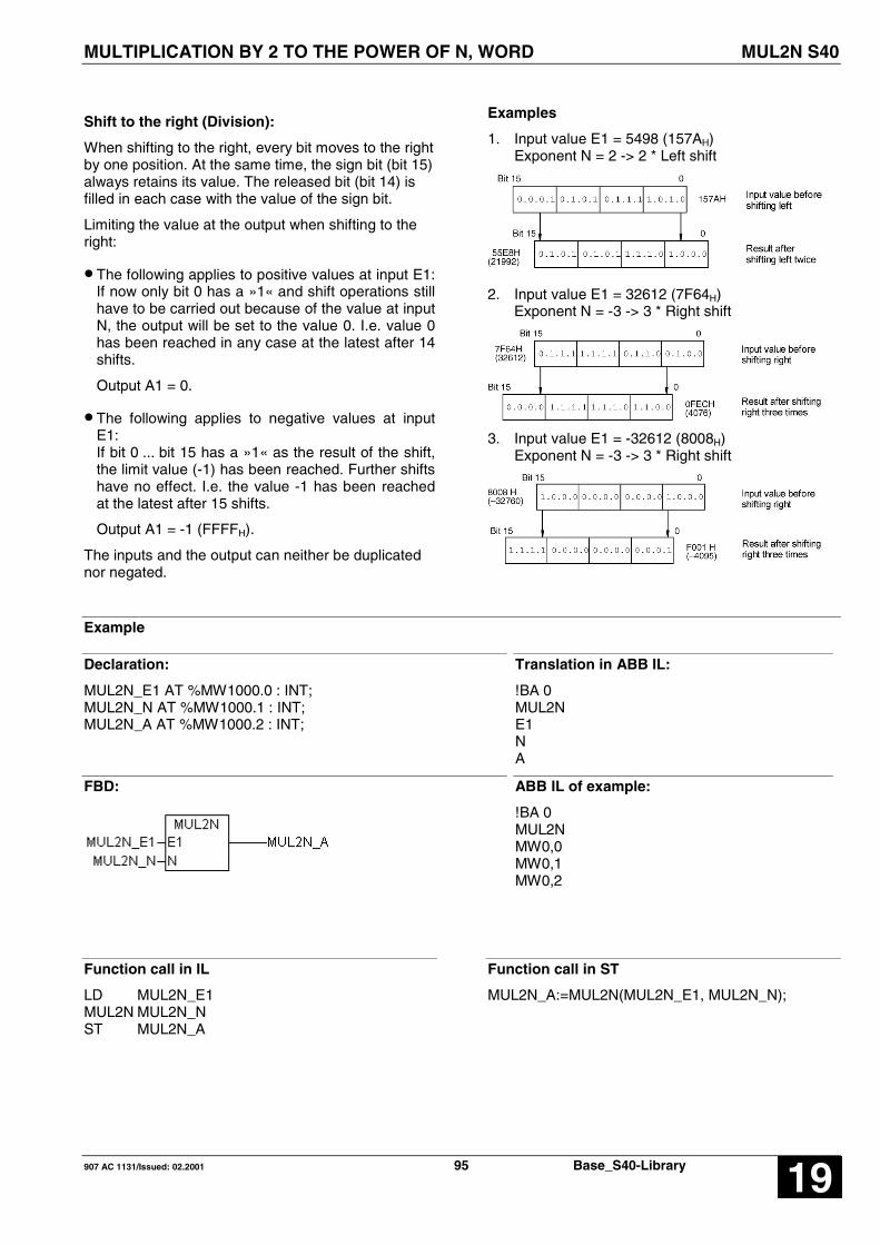
MULTIPLICATION BY 2 TO THE POWER OF N, WORD MUL2N S40
907 AC 1131/Issued: 02.2001 95 Base_S40-Library 19
Shift to the right (Division):
When shifting to the right, every bit moves to the rightby one position. At the same time, the sign bit (bit 15)always retains its value. The released bit (bit 14) isfilled in each case with the value of the sign bit.
Limiting the value at the output when shifting to theright:
• The following applies to positive values at input E1:If now only bit 0 has a »1« and shift operations stillhave to be carried out because of the value at inputN, the output will be set to the value 0. I.e. value 0has been reached in any case at the latest after 14shifts.
Output A1 = 0.
• The following applies to negative values at inputE1:If bit 0 ... bit 15 has a »1« as the result of the shift,the limit value (-1) has been reached. Further shiftshave no effect. I.e. the value -1 has been reachedat the latest after 15 shifts.
Output A1 = -1 (FFFFH).
The inputs and the output can neither be duplicatednor negated.
Examples
1. Input value E1 = 5498 (157AH)Exponent N = 2 -> 2 * Left shift
2. Input value E1 = 32612 (7F64H)Exponent N = -3 -> 3 * Right shift
3. Input value E1 = -32612 (8008H)Exponent N = -3 -> 3 * Right shift
Example
Declaration:
MUL2N_E1 AT %MW1000.0 : INT;MUL2N_N AT %MW1000.1 : INT;MUL2N_A AT %MW1000.2 : INT;
Translation in ABB IL:
!BA 0MUL2NE1NA
FBD: ABB IL of example:
!BA 0MUL2NMW0,0MW0,1MW0,2
Function call in IL
LD MUL2N_E1MUL2N MUL2N_NST MUL2N_A
Function call in ST
MUL2N_A:=MUL2N(MUL2N_E1, MUL2N_N);
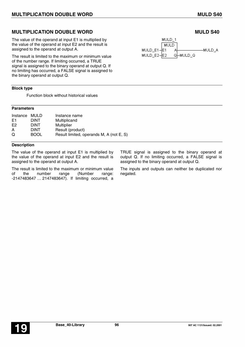
MULTIPLICATION DOUBLE WORD MULD S40
Base_40-Library 96 907 AC 1131/Issued: 02.200119
MULTIPLICATION DOUBLE WORD MULD S40
The value of the operand at input E1 is multiplied bythe value of the operand at input E2 and the result isassigned to the operand at output A.
The result is limited to the maximum or minimum valueof the number range. If limiting occurred, a TRUEsignal is assigned to the binary operand at output Q. Ifno limiting has occurred, a FALSE signal is assigned tothe binary operand at output Q.
Block type
Function block without historical values
Parameters
Instance MULD Instance nameE1 DINT MultiplicandE2 DINT MultiplierA DINT Result (product)Q BOOL Result limited, operands M, A (not E, S)
Description
The value of the operand at input E1 is multiplied bythe value of the operand at input E2 and the result isassigned to the operand at output A.
The result is limited to the maximum or minimum valueof the number range (Number range:-2147483647 … 2147483647). If limiting occurred, a
TRUE signal is assigned to the binary operand atoutput Q. If no limiting occurred, a FALSE signal isassigned to the binary operand at output Q.
The inputs and outputs can neither be duplicated nornegated.

MULTIPLICATION DOUBLE WORD MULD S40
907 AC 1131/Issued: 02.2001 97 Base_S40-Library 19
Example
Declaration:
MULD_1 : MULD;MULD_E1 AT %MD2000.0 : DINT;MULD_E2 AT %MD2000.1 : DINT;MULD_A AT %MD2000.2 : DINT;MULD_Q AT %M0.0 : BOOL;
Translation in ABB IL:
!BA 0MULDE1E2AQ
FBD: ABB IL of example:
!BA 0MULDMD0,0MD0,1MD0,2M0,0
Function call in IL
CAL MULD_1(E1 := MULD_E1,E2 := MULD_E2)
LD MULD_1.QST MULD_QLD MULD_1.AST MULD_A
Note: In IL, the function call has to be performed inone line.
Function call in ST
MULD_1 (E1 := MULD_E1,E2 := MULD_E2);
MULD_A := MULD_1.A;MULD_Q := MULD_1.Q;

MULTIPLICATION WITH DIVISION MULDI S40
Base_40-Library 98 907 AC 1131/Issued: 02.200119
MULTIPLICATION WITH DIVISION MULDI S40
The operand value at input E1 is multiplied by theoperand value at input E2, the intermediate result isdivided by the operand value at E3 and then the resultis assigned to output A.
The result is limited to the maximum or minimum valueof the number range.
Block type
Function
Parameters
E1 INT MultiplicandE2 INT MultiplierE3 INT DivisorA INT Result
Description
The operand value at input E1 is multiplied by theoperand value at input E2, the intermediate result isdivided by the operand value at E3 and then the resultis assigned to output A.
Internal, the block performs the multiplication anddivision with the accuracy of a double word (32 bit).Only when assigning the result to output A, the limitingto the accuracy of a word (16 bit) is carried out. If the
remainder of the division is > 0,5, the result is roundedup. If a numerical overflow occurs during the division(e.g. division by zero), the correct signed limit of thenumber range is applied at output A.
The result is limited to the maximum value 32767 andthe minimum value -32767.
The inputs and the output can neither be duplicated nornegated.

MULTIPLICATION WITH DIVISION MULDI S40
907 AC 1131/Issued: 02.2001 99 Base_S40-Library 19
Example
Declaration:
MULDI_E1 AT %MW1000.0 : INT;MULDI_E2 AT %MW1000.1 : INT;MULDI_E3 AT %MW1000.2 : INT;MULDI_A AT %MW1000.3 : INT;
Translation in ABB IL:
!BA 0MULDIE1E2E3A
FBD: ABB IL of example:
!BA 0MULDIMW0,0MW0,1MW0,2MW0,3
Function call in IL
LD MULDI_E1MULDI MULDI_E2,MULDI_E3ST MULDI_A
Function call in ST
MULDI_A := MULDI (MULDI_E1,MULDI_E2,MULDI_E3);

NEGATION WORD NEGW S40
Base_40-Library 100 907 AC 1131/Issued: 02.200119
NEGATION WORD NEGW S40
The value of the operand at input E is negated and theresult is assigned to the operand at output A.
Block type
Function
Parameters
E1 INT Input valueA INT Negated value
Description
The value of the operand at input E is negated andthe result is assigned to the operand at output A
Number range :
Low limit : 8000H - 32768High limit 7FFFH + 32767Note : if E1 = -32768 then A = +32767.
The input and the output can neither be duplicatednor negated.
Example
Declaration:
NEGW_E1 AT %MW1000.0 : INT;NEGW_A AT %MW1000.1 : INT;
Translation in ABB IL:
!BA 0NEGWE1A
FBD: ABB IL of example:
!BA 0NEGWMW0,0MW0,1
Function call in IL
LD NEGW_E1NEGWST NEGW_A
Function call in ST
NEGW_A := NEGW(NEGW_E1);

PULSES GENERATOR NPULSE S40
907 AC 1131/Issued: 02.2001 101 Base_S40-Library 19
PULSES GENERATOR NPULSE S40
The function block generates pulsesequences with specific frequenciesand specific number of pulses. Thus,it can be used for the activation ofstepper motors.
The pulse sequences are available atoutput A62,00 / %QX62.00.
Block type
Function block with historical values
Parameters
Instance NPULSE Instance nameVAL BOOL EnablingRESET BOOL ResetFREQ INT FrequencyNB INT Number of pulsesRDY BOOL Ready, operands M, A (not E, S)VAL_P INT Number of processed pulses
Description
The function block generates pulse sequences withspecific frequencies and specific number of pulses.Thus, it can be used for the activation of steppermotors.
The pulse sequences are available at outputA62,00 / %QX62.00.
At output VAL_P, the currently generated number ofpulses is displayed. The rising edge at the input VALstarts the pulse generator from the beginning.The firstperiod starts with a high signal.
VAL BOOL
Enabling the output of the impulse sequence at thefixed output A62,00 / %QX62.0.
FALSE/TRUE edge at the input VAL :The pulse mode is validated.
A62,00 / %QX62.00 can not be used normally.
RESET BOOL
RESET = FALSE stops the pulse generator, the outputA62,00 / %QX62.0 is set to FALSE till RESET = TRUE.
FREQ INT
Frequency of the pulse sequence:
Pulse frequency : 10 Hz to 2,604 kHz
Formula for frequency calculation:
Frequency [Hz] = 1000000 / ((256 - FREQ)*384)
FREQ Frequency
012
10,173 Hz11,212 Hz10,253 Hz
10 10,586 Hz
100 16,693 Hz
254255
1,302 kHz2,604 kHz
< 0> 255
10,173 Hz2,604 kHz
NB INT
Number of pulses to be generated.
If NB < 0 then the function block NPULSE generatescontinuously pulses till RESET input is validated.

PULSES GENERATOR NPULSE S40
Base_40-Library 102 907 AC 1131/Issued: 02.200119
RDY BOOL
Ready bitRDY = FALSE Pulses are generated
RDY = TRUE Pulse sequence is finished
VAL_P INT
Number of pulses elapsed.
This number is estimated by the function block everycycle time. It doesn’t represent the exact value.
The internal memory bit %QX62.00 is disabled duringpulses are generating.
Example
Declaration:
NPULSE1 : NPULSE;NPULSE_VAL AT %MX0.0 : BOOL;NPULSE_RESET AT %MX0.1 : BOOL;NPULSE_FREQ AT %MW1000.0 : INT;NPULSE_NB AT %MW1000.1 : INT;NPULSE_RDY AT %MX0.2 : BOOL;NPULSE_VAL_P AT %MW1000.2 : INT;
Translation in ABB IL:
!BA 0NPULSEVALRESETFREQNBRDYVAL_P
FBD: ABB IL of example:
!BA 0NPULSEM0,0M0,1MW0,0MW0,1M0,2MW0,2
Function call in IL
CAL NPULSE1(VAL := NPULSE_VAL,RESET := NPULSE_RESET,FREQ := NPULSE_FREQ,NB := NPULSE_NB)
LD NPULSE1.RDYST NPULSE_RDYLD NPULSE1.VAL_PST NPULSE_VAL_P
Note: In IL, the function call has to be performed inone line.
Function call in ST
NPULSE1 (VAL := NPULSE_VAL,RESET := NPULSE_RESET,FREQ := NPULSE_FREQ,NB := NPULSE_NB);
NPULSE_RDY := NPULSE1.RDY;NPULSE_VAL_P := NPULSE1.VAL_P;

PACK BINARY VARIABLES IN WORD PACK(4..16) S40
907 AC 1131/Issued: 02.2001 103 Base_S40-Library 19
PACK BINARY VARIABLES IN WORD PACK(4..16) S40
This block packs n binary variables into one wordvariable.
Block type
Function block without historical values
Parameters
Instance PACK Instance nameN INT Number of binary variables to be packedB0..B15 BOOL Binary variable to be packedA INT Word variable
Description
The PACK number indicates the maximum number ofbits to pack. The following PACK blocks are available:
PACK4 PACK for max. 2 binary variablesPACK8 PACK for max. 8 binary variablesPACK16 PACK for max. 16 binary variables
This block packs n binary variables into one wordvariable.
n INT
At input n, the number of binary variables to be packedis specified.
The following applies:
1 < n < 4,(8, 16)n = 0 is not allowed! (default = 1)
B0…B15 BOOL
The binary variables to be packed are specified at theinputs B0 ... Bn-1.
A INT
The value of each binary variable at the inputsB0 ... Bn-1 is loaded into the corresponding bit(bit 0 ... bit 15) of the variable at output A.
Assignment:B0 → bit0 of the output variableB1 → bit1 of the output variable. .B15 → bit15 of the output variable
Note:If the user plans less than 16 binary input variables, theunnecessary bits of the output variable are set to thevalue FALSE.

PACK BINARY VARIABLES IN WORD PACK(4..16) S40
Base_40-Library 104 907 AC 1131/Issued: 02.200119
Example
Declaration:
PACK_16 : PACK;PACK_B0 AT %MX0.0 : BOOL;PACK_B1 AT %MX0.1 : BOOL;PACK_B2 AT %MX0.2 : BOOL;PACK_B3 AT %MX0.3 : BOOL;PACK_A AT %MW1000.0 : INT;
Translation in ABB IL:
!BA 0PACK#nB0B1B2B3A
FBD: ABB IL of example:
!BA 0PACK#4M0,0M0,1M0,2M0,3MW0,0
Function call in IL
CAL PACK_1(n := 4,B0 := PACK_B0,B1 := PACK_B1,B2 := PACK_B2,B3 := PACK_B3)
LD PACK_1.AST PACK_A
Note: In IL, the function call has to be performed inone line.
Function call in ST
PACK_1 (n := 16,B0 := PACK_B0,B1 := PACK_B1,B2 := PACK_B2,B3 := PACK_B3);
PACK_A:=PACK_1.A;

PULSE DURATION MODULATOR PDM S40
907 AC 1131/Issued: 02.2001 105 Base_S40-Library 19
PULSE DURATION MODULATOR PDM S40
This function block generates a pulse duration-modulated binary signal at its PULS output.
The pulse duty ratio is specified at the t_TA input andthe period duration for the output signal is specified atthe TA_T input.
Block type
Function block with historical values
Parameters
Instance PDM Instance namet_TA INT Pulse duty ratioTA_T INT Period duration referred to the cycle timePULS BOOL Pulse duration modulated signal
Description
This function block generates a pulse duration-modulated binary signal at its PULS output.
The pulse duty ratio is specified at the t_TA input andthe period duration for the output signal is specified atthe TA_T input.
The inputs and the output can neither be duplicated nornegated nor inverted.
t_TA INT
The required pulse duty ratio for the output signalPULS is specified at input t_TA. At the same time, TAis the period duration of the signal at output PULS and tis the time within the period duration TA during whichthe output signal assumes a TRUE level. The specifiedvalue for the required pulse duty ratio at input t_TAmust be specified in scaled form. To do this, therequired pulse duty ratio must be multiplied by thevalue 32767 and rounded to an integer number. Theresulting numerical value is then specified at inputt_TA.
Boundary condition for t: t > T
I.e. the required duty cycle of the output signal must behigher than the cycle time of the PLC program (T).
The following relationship applies to the specification ofthe pulse duty ratio at input t_TA:
Scaled value at input t_TA results in pulse duty ratio atthe output PULS:
Input t_TA Output PULSNegative value 0 ( 0 %)0 (0 * 32767) 0 ( 0 %): : :: : :16384 (0,5 * 32767) 0,5 ( 50 %): : :: : :32767 (1 * 32767) 1 (100 %)
TA_T INT
The required period duration TA for the signal at outputPULS is specified at input TA_T. At the same time, theperiod duration TA must be scaled to the cycle time T.
Boundary condition for TA:
• TA must be an integer multiple of T (TA = n * T)
• TA >> T > 0; the higher TA is in relation to T, themore exactly the required pulse duty ratio is kept
Example:TA > 10 * T → inaccuracy of the pulse duty ratio atoutput PULS < 10%.
If a value TA_T < 0 is specified for TA_T, the functionblock automatically replaces this meaningless value by32767.

PULSE DURATION MODULATOR PDM S40
Base_40-Library 106 907 AC 1131/Issued: 02.200119
PULS BOOL
The pulse duration modulated signal is available atoutput PULS.
Combination of the PDM block with a controller
If the PDM function block is connected to the output ofa controller in order to realize a »switching« controller,the following boundary conditions apply:
– Period duration TA of the PDM = sampling time ofthe controller.
– Period of the pulse signal must be synchronous withthe period of the controller sampling time.
These boundary conditions are fulfilled by planning thecontroller in the same PLC program as the PDM, butwithin one run number block. By means of the runnumber block, the sampling time of the controller isprolonged by an integer multiple of the cycle time.Therefore, the controller is processed less frequentlywithin the run number block than the PDM outside ofthe run number block.
Example
Required:
– Pulse duty ratio: t_TA = 0,25 (25 %)– Period duration: TA = 800 ms (only an integer
multiple of the PLC cycle time is possible)– Cycle time: T = 100 ms
Block parameters to be specified:
– Value at input t_TA: 8192 (0,25 * 32767)– Value at input TA_T: 8 (800 ms/100 ms)
Example
Declaration:
PDM_1 : PDM;PDM_t_TA AT %MW1000.0 : INT;PDM_TA_t AT %MW1000.1 : INT;PDM_PULS AT %MX0.0 : BOOL;
Translation in ABB IL:
!BA 0PDMt_TATA_tPULS
FBD: ABB IL of example:
!BA 0PDMMW0,0MW0,1M0,0
Function call in IL
CAL PDM_1(t_TA := PDM_t_TA,TA_T := PDM_TA_t)
LD PDM_1.PULSST PDM_PULS
Note: In IL, the function call has to be performed inone line.
Function call in ST
PDM_1 (t_TA := PDM_t_TA,TA_T := PDM_TA_t);
PDM_PULS:=PDM_1.PULS;

PROPORTIONAL INTEGRAL CONTROLLER PI S40
907 AC 1131/Issued: 02.2001 107 Base_S40-Library 19
PROPORTIONAL INTEGRAL CONTROLLER PI S40
The PI controller changes the value atits output Y (manipulated variable) untilthe value at input X (controlledvariable) is equal to the value at inputW (command variable).
Block type
Function block with historical values
Parameters
Instance PI Instance nameW INT Command variable (set point)X INT Controlled variable (actual value)KP INT Proportional coefficient, specified as a percentage valueTN_TZ INT Integral action time scaled to the PLC cycle timeOG INT High limit for the manipulated variable YUG INT Low limit for the manipulated variable YSET BOOL Enabling for setting the manipulated variable Y to the initial value INITINIT INT Initial value for the manipulated variable YRES BOOL Reset of the manipulated variable Y to 0OG_MELD BOOL High limit has been reached, operands M, A (not E, S)UG_MELD BOOL Low limit has been reached, operands M, A (not E, S)Y INT Output for the manipulated variable Y
Description
The PI controller changes the value at its output Y(manipulated variable) until the value at input X(controlled variable) is equal to the value at input W(command variable).
Control algorithm: Simple rectangle rule
KP W-X KPY = ––– * –––––– + YI(z-1) + ––– * (W-X)
100 TN_TZ 100
With: YI(z-1) is the integral component from theprevious program cycle
Transfer function:
1F(s) = KP * (1+ ––––––)
s * TN
The inputs and outputs can neither be duplicated nornegated/inverted.

PROPORTIONAL INTEGRAL CONTROLLER PI S40
Base_40-Library 108 907 AC 1131/Issued: 02.200119
PI controller: Surge-free transition from the specifiedvalue to control operation
PI controller: Surging transition from the specifiedinitial value to control operation

PROPORTIONAL INTEGRAL CONTROLLER PI S40
907 AC 1131/Issued: 02.2001 109 Base_S40-Library 19
W INT
The command variable (set point) is specified at inputW.
X INT
The controlled variable (actual value) is specified atinput X.
KP INT
The proportional coefficient is specified at input KP.This value is specified as a percentage value. Positiveor negative values are possible.
Example:1 = 1 percent
55 = 55 percent100 = 100 percent
1000 = 1000 percent-500 = -500 percent
• 1 percent means that the block multiplies the systemdeviation by the factor 0.01 (see also controlalgorithm)
• 100 percent means that the block multiplies thesystem deviation by the factor 1 (see also controlalgorithm)
• 1000 percent means that the block multiplies thesystem deviation by the factor 10 (see also controlalgorithm)
Generally, proportional coefficients of more than 1000percent are not meaningful in control systems.
TN_TZ INT
The integral action time TN is scaled to the PLC cycletime TZ and is specified at input TN_TZ.
Value range: 0 < TN_TZ < 328
• If values are specified which are not within theadmissible value range the PLC generally uses thevalue 328.
• A large integral action time TN can be achieved bychoosing a large cycle time T, too. If the block is usedwithin a run number block, the cycle time of the runnumber block is valid for block INTK and not the cycletime (KD 0,0) of the PLC program.
Limiting the manipulated variable Y
OG INTUG INT
The controller output Y (manipulated variable) can belimited
– to a maximum value by specifying a limit at input OG(high limit)
– to a minimum value by specifying a limit at input UG(low limit)
The high and low limits also apply to the controller’sinternal I component. I.e the I component can onlyassume values between the high and low limits. If themanipulated variable Y reaches one of the two limits,the I component of the controller is no longer changed.This prevents the I component from drifting in the eventof limiting of the controller output Y, assumingmeaningless values from the point of view of controland, in certain circumstances, not returning to theoperating range until after a very long time. Thisresponse of a controller is also referred to as a »specialanti-reset windup measure«.
Setting and resetting the controller
SET BOOLINIT INTRES BOOL
Setting the controller to an initial value
– The output Y of the controller is set to the initial valuespecified at the INIT input by means of a TRUEsignal at input SET.
– A TRUE signal at input RES (reset) is equivalent tospecifying the initial value 0 (see above).
Surge-free setting/resetting
– The output Y of the controller is set to the initial valuespecified at the INIT input by means of a TRUEsignal at the binary input SET.
– A TRUE signal at input RES (reset) is equivalent tospecifying the initial value 0.
In doing so, adjustment to the initial value is performedinternal to the controller. This adjustment is a shift ofthe controller output from the momentary value to therequired initial value. Now, the controller continuesoperating from this initial value precisely as it wouldhave done at the old operating point before the shift,i.e. without surges. The I component of the controller isdefined so that the sum of the P component and the Icomponent just results in the initial value.
Advantage of surge-free setting:– Control as from the new initial value is devoid of
surges.
Disadvantage of surge-free setting:– The equation applies: I_component = INIT -
P_component
In certain circumstances, the I component is set to highvalues and may take very long before this »wrong« Icomponent from the point of view of control isdissipated again.

PROPORTIONAL INTEGRAL CONTROLLER PI S40
Base_40-Library 110 907 AC 1131/Issued: 02.200119
Surging setting/resetting
– The output Y of the controller is set to the initial valuespecified at the INIT input by means of a TRUEsignal at input SET.
– A TRUE signal at input RES (reset) is equivalent tospecifying the initial value 0.
In the event of surging setting or resetting of thecontroller, the I component is set equal to the initialvalue. To do this, the P component must besuppressed during the setting procedure.
The following applies: I component = INIT
Surging setting to an initial value is achieved by thefollowing measure during the setting procedure:
– Specifying the value 0 at input KP.
This measure renders the controller’s P componentinactive. The controller output Y assumes the initialvalue during the set cycle.The P component is enabled again after the set cycle.From the initial value, the controller output Y jumpsaccording to the P component of the controller.
Advantage of surging setting:– The I component is not set to »wrong« values from
the point of view of control.
Disadvantage of surging setting:– Not surging-free
Y INT
The manipulated variable Y of the controller is appliedat output Y.
OG_MELD BOOL
Output OG_MELD indicates whether the value atoutput Y has reached the specified top limit.
OG_MELD = FALSE limit has not been reached.OG_MELD = TRUE limit has been reached.
UG_MELD BOOL
Output UG_MELD indicates whether the value atoutput Y has reached the specified low limit.
UG_MELD = FALSE limit has not been reached.UG_MELD = TRUE limit has been reached.

PROPORTIONAL INTEGRAL CONTROLLER PI S40
907 AC 1131/Issued: 02.2001 111 Base_S40-Library 19
Example
Declaration:
PI_1: PI;PI_W AT %MW1000.0: INT;PI_X AT %MW1000.1: INT;PI_KP AT %MW3001.0: INT := 100;PI_TN_TZ AT %MW3001.1: INT := 20;PI_OG AT %MW3001.2: INT := 20000;PI_UG AT %MW3001.3: INT := 0;PI_SET AT %MX0.0: BOOL;PI_INIT AT %MW3001.4: INT := 10000;PI_RES AT %MX0.1: BOOL;PI_OG_MELD AT %MX0.2: BOOL;PI_UG_MELD AT %MX0.3: BOOL;PI_Y AT %MW1000.2: INT;
Translation in ABB IL:
!BA 0PIWXKPTN_TZINITSETRESOGUGYOG_MELDUG_MELD
FBD: ABB IL of example:
!BA 0PIMW0,0MW1,1KW1,0 ; 100KW1,1 ; 20M0,0M0,1KW1,4 ; 10000M0,0M0,1KW1,2 ; 20000KW1,3 ; 0MW0,2M0,2M0,3
Function call in IL
CAL PI_1(W := PI_W, X := PI_X, KP := PI_KP,TN_TZ := PI_TN_TZ, OG := PI_OG, UG := PI_UG,SET := PI_SET, INIT := PI_INIT, RES := PI_RES)
LD PI_1.OG_MELDST PI_OG_MELDLD PI_1.UG_MELDST PI_UG_MELDLD PI_1.YST PI_Y
Note: In IL, the function call has to be performed inone line.
Function call in ST
PI_1(W := PI_W, X := PI_X, KP := PI_KP,TN_TZ := PI_TNTZ, OG := PI_OG,UG := PI_UG, SET := PI_SET, INIT := PI_INIT,RES := PI_RES);
PI_OG_MELD:=PI_1.OG_MELD;PI_UG_MELD:=PI_1.UG_MELD;PI_Y:=PI_1.Y;

PIDT1 CONTROLLER PIDT1 S40
Base_40-Library 112 907 AC 1131/Issued: 02.200119
PIDT1 CONTROLLER PIDT1 S40
The PI controller changes its output Y (manipulatedvariable) until input X (controlled variable) is equal toinput W (command variable).
Block type
Function block with historical values
Parameters
Instance PIDT1 Instance nameW INT Command variable (set point)X INT Controlled variable (actual value)KP INT Proportional coefficient, specified as a percentage valueTN_TZ INT Integral action time scaled to the PLC cycle timeTV_TZ INT Derivative action time scaled to the PLC cycle timeT1_TZ INT Returning time scaled to the PLC cycle timeDT1_FR BOOL Enable DT componentOG INT High limit for the manipulated variable YUG INT Low limit for the manipulated variable YSET BOOL Enable for setting to initial value INITINIT INT Initial value for the manipulated variable YRES INT Reset of the manipulated variable Y to 0OG_MELD BOOL High limit has been reached, operands M, A (not E, S)UG_MELD BOOL Low limit has been reached, operands M, A (not E, S)Y INT Output for the manipulated variable Y
Description
The PI controller changes its output Y (manipulatedvariable) until input X (controlled variable) is equal toinput W (command variable).
Transfer function:
1 s * TVF(s) = KP * (1 + ––––– + ––––––––)
s * TN 1 + (s T1)
Control algorithm: Simple rectangle rule:
KP*XD KP XD T1_TZ 1 TV KPY = –––– + ––– * ––––– + YI(z-1) + –––––––– * (YDTI(z-1) + –––– * –– * ––– * (XD – XD(z-1)))
100 100 TN_TZ 1+(T1_TZ) T1_TZ TZ 100
Where:YI(z-1): The integral portion from the previous programcycle
(YDTI(z-1) The differential portion from theprevious program cylce
XD(z-1): Control system difference from theprevious program cycle
The inputs and outputs can neither be duplicated nornegated/inverted.

PIDT1 CONTROLLER PIDT1 S40
907 AC 1131/Issued: 02.2001 113 Base_S40-Library 19
PIDT1 controller: Surge-free transition from thespecified value to control operation
PIDT1 controller: Surging transition from thespecified initial value to control operation

PIDT1 CONTROLLER PIDT1 S40
Base_40-Library 114 907 AC 1131/Issued: 02.200119
W INT
The command variable (set point) is specified at inputW.
X INT
The controlled variable (actual value) is specified atinput X.
KP INT
The proportional coefficient is specified at input KP.This value is specified as a percentage value. Positiveor negative values are possible.
Example:
1 = 1 percent55 = 55 percent
100 = 100 percent1000 = 1000 percent-500 = -500 percent
• 1 percent means that the block multiplies the systemdeviation by the factor 0.01 (see also controlalgorithm)
• 100 percent means that the block multiplies thesystem deviation by the factor 1 (see also controlalgorithm)
• 1000 percent means that the block multiplies thesystem deviation by the factor 10 (see also controlalgorithm)
Generally, proportional coefficients of more than 1000percent are not meaningful in control systems.
TN_TZ INT
The integral action time TN is scaled to the PLC cycletime TZ and is specified at input TN_TZ.
Value range: 0 < TN_TZ < 328
• If values are specified which are not within theadmissible value range, the PLC generally uses thevalue 328.
• A large integral action time TN can be achieved bychoosing a large cycle time T, too. If the block is usedwithin a run number block, the cycle time of the runnumber block is valid for block INTK and not the cycletime (KD00,00 / MD4000.0) of the PLC program.
TV_TZ INT
The derivative action time TV is scaled to the PLCcycle time TZ and is specified at input TV_TZ:(0 < TN_TZ < 32767).
T1_TZ INT
The returning time T1 is scaled to the PLC cycle timeTZ and is specified at input T1_TZ:(0 < TN_TZ < 32767).
The returning time is the time in which the DT1component has decreased to approximately 37% of itsinitial value.
Invalid time parameters:Every time value is set to the maximum positive value32767 if the time value at the input is erroneouslyspecified as less than or equal to »0«.
DT1_FR BOOL
The DT1 component of the controller can be activatedor deactivated by means of the D-FR input.
D_FR Meaning
0 DT1 component isdeactivated
→ pure PIcontroller
1 DT1 component isactivated
→ PIDT1 controller
In the following cases, from the control point of view itis often disturbing and not meaningful for the DT1component to be active:
– During activations– In the event of large system deviations– When setting the controller to a specified initial value– When resetting the controller to the value 0
The command and controlled variables can becompared outside of the controller. Depending on thiscomparison, the DT1 component can be activated ordeactivated specifically using the D-FR input.
For example, the activation can be restricted to thecondition that the system deviation is within a requiredbandwidth. I.e. the DT1 component is only active if thecontrolled variable fluctuates around the set point withina specific bandwidth. The DT1 component isdeactivated if the controlled variable leaves thistolerance band.

PIDT1 CONTROLLER PIDT1 S40
907 AC 1131/Issued: 02.2001 115 Base_S40-Library 19
Limiting the manipulated variable Y
OG INTUG INT
The controller output Y (manipulated variable) can belimited
– to a maximum value by specifying a limit at inputOG (high limit)
– to a minimum value by specifying a limit at inputUG (low limit).
The high and low limits also apply to the controller’sinternal I component. I.e the I component can onlyassume values between the high and low limits. If themanipulated variable Y reaches one of the two limits,the controller's I component is no longer changed.
This prevents the I component from drifting in theevent of limiting of the controller output Y, assumingmeaningless values from the point of view of controland, in certain circumstances, not returning to theoperating range until after a very long time. Thisresponse of a controller is also referred to as a»special anti-reset windup measure«.
Setting and resetting the controller
SET BOOLINIT INTRES BOOL
Setting the controller to an initial value
– The output Y of the controller is set to the initialvalue specified at the INIT input by means of aTRUE signal at input SET.
– A 1 signal at input RES (reset) is equivalent tospecifying the initial value 0 (see above).
Surge-free setting/resetting
– Output Y of the controller is set to the initial valuespecified at the INIT input by means of a TRUEsignal at the binary input SET.
– A 1 signal at input RES (reset) is equivalent tospecifying the initial value 0.
In doing so, adjustment to the initial value isperformed internal to the controller. This adjustmentis a shift of the controller output from the momentaryvalue to the required initial value. Now, the controllercontinues operating from this initial value precisely asit would have done at the old operating point beforethe shift, i.e. without surges. The controller’s Icomponent is defined in a way that the sum of the P,I and the DT1 component just results in the initialvalue.
Advantage of surge-free setting:
– Control as from the new initial value is devoid ofsurges.
Disadvantage of surge-free setting:– The equation applies:
I component = INIT – P component – DT1 comp.
In certain circumstances, the I component is set tohigh values and may take very long before this»wrong« I component from the point of view ofcontrol is dissipated again.
Surging setting/resetting
– The output Y of the controller is set to the initialvalue specified at the INIT input by means of aTRUE signal at input SET.
– A 1 signal at input RES (reset) is equivalent tospecifying the initial value 0.
– In the event of surging setting or resetting of thecontroller the I component is set equal to the initialvalue. To do this, the P component and the DT1component must be suppressed during settingprocedure.
The following applies: I component = INIT
Surging setting to an initial value is achieved by thefollowing measures during setting procedure:
– Deactivation of the DT1 component via the D-FRcontrol input and
– Specifying the value 0 at the input KP.
These measures render the P component and theDT1 component inactive during setting of thecontroller.
The controller output assumes the initial value duringthe set cycle.
The P component and the DT1 component areenabled again after the set cycle. From the initialvalue, the controller output Y jumps according to theP component and the DT1 component of thecontroller.
Advantage of surging setting:– The I component is not set to »wrong« values from
the point of view of control.
Disadvantage of surging setting:– Not surging-free
Y INT
The manipulated variable Y of the controller isapplied at output Y.

PIDT1 CONTROLLER PIDT1 S40
Base_40-Library 116 907 AC 1131/Issued: 02.200119
OG_MELD BOOL
Output OG_MELD indicates whether the value atoutput Y has reached the specified top limit.
OG_MELD = FALSE limit has not been reached.OG_MELD = TRUE limit has been reached.
UG_MELD BOOL
Output UG_MELD indicates whether the value atoutput Y has reached the specified low limit.
UG_MELD = FALSE limit has not been reached.UG_MELD = TRUE limit has been reached.
Example
Declaration:
PIDT1_1 : PIDT1;PIDT1_W AT %MW1000.0: INT;PIDT1_X AT %MW1000.1: INT;PIDT1_KP AT %MW3001.0: INT := 100;PIDT1_TN_TZ AT %MW3001.1: INT := 20;PIDT1_TV_TZ AT %MW3001.2 : INT := 0;PIDT1_T1_TZ AT %MW3001.3 : INT := 0;PIDT1_DT1_FR AT %MX0.4 : BOOL;PIDT1_OG AT %MW3001.5: INT := 20000;PIDT1_UG AT %MW3001.6: INT := 0;PIDT1_SET AT %MX0.0: BOOL;PIDT1_INIT AT %MW3001.7: INT := 10000;PIDT1_RES AT %MX0.1: BOOL;PIDT1_OG_MELD AT %MX0.2: BOOL;PIDT1_UG_MELD AT %MX0.3: BOOL;PIDT1_Y AT %MW1000.2: INT;
Translation in ABB IL:
!BA 0PIDT1WXKPTN_TZTV_TZT1_TZDT1_FRINITSETRESOGUGYOG_MELDUG_MELD
FBD: ABB IL of example:
!BA 0PIMW0,0MW1,1KW1,0 ; 100KW1,1 ; 20KW1,2 ; 0KW1,3 ; 0M0,4M0,0M0,1KW1,5 ; 10000M0,0M0,1KW1,6 ; 20000KW1,7 ; 0MW0,2M0,2M0,3

PIDT1 CONTROLLER PIDT1 S40
907 AC 1131/Issued: 02.2001 117 Base_S40-Library 19
Function call in IL
CAL PIDT1_1(W := PIDT1_W,X := PIDT1_X,KP := PIDT1_KP,TN_TZ := PIDT1_TNTN,TV_TZ := PIDT1_TVTZ,T1_TZ := PIDT1_T1_TZ,DT1_FR := PIDT1_DT1_FR,OG := PIDT1_OG,UG := PIDT1_UG,SET := PIDT1_SET,INIT := PIDT1_INIT,RES := PIDT1_RES)
LD PIDT1_1.OG_MELDST PIDT1_OG_MELDLD PIDT1_1.UG_MELDST PIDT1_UG_MELDLD PIDT1_1.YST PIDT1_Y
Note: In IL, the function call has to be performed inone line.
Function call in ST
PIDT1_1 W := PIDT1_W,X := PIDT1_X,KP := PIDT1_KP,TN_TZ := PIDT1_TNTN,TV_TZ := PIDT1_TVTZ,T1_TZ := PIDT1_T1_TZ,DT1_FR := PIDT1_DT1_FR,OG := PIDT1_OG,UG := PIDT1_UG,SET := PIDT1_SET,INIT := PIDT1_INIT,RES := PIDT1_RES);
PIDT1_OG_MELD := IDT1_1.OG_MELD;PIDT1_UG_MELD := IDT1_1.UG_MELD;PIDT1_Y := IDT1_1.Y;

RESET MEMORY , DOMINATING RS S40
Base_40-Library 118 907 AC 1131/Issued: 02.200119
RESET MEMORY , DOMINATING RS S40
A status TRUE at the input SET sets the operand Q1 tothe status TRUE.
A status TRUE at the input RESET1 resets theoperand Q1 to the status FALSE.
=> dominating RESET
Block type
Function block without historical values
Parameters
Instance RS Instance nameSET BOOL Set inputRESET1 BOOL Reset inputQ1 BOOL Flip-flop output
Description
A status TRUE at the input SET sets the operand Q1to the status TRUE.
A status TRUE at the input RESET1 resets theoperand Q1 to the status FALSE.
A simultaneous TRUE status at the inputs SET andRESET1 sets operand Q1 to a status FALSE(dominating reset )
A status FALSE at the input SET or RESET1 has noinfluence on the operand Q1
Example
Declaration:
RS_1 : RS;RS_SET AT %MX0.0 : BOOL;RS_RESET1 AT %MX0.1 : BOOL;RS_Q1 AT %MX0.2 : BOOL;
Translation in ABB IL:
! SET=S Q1! RESET1=R Q1
FBD: ABB IL of example:
! M0,0=S M0,2! M0,1=R M0,2
Function call in IL
CAL RS_1(SET = RS_SET,RESET1 := RS_RESET)
LD RS_1.Q1ST RS_Q
Function call in ST
RS_1 ( SET := RS_SET,RESET1 := RS_RESET);
RS_Q := RS_1.Q1;

SERIAL LINE INITIALIZATION SINIT S40
907 AC 1131/Issued: 02.2001 119 Base_S40-Library 19
SERIAL LINE INITIALIZATION SINIT S40
Serial interface initialization function block.
The function block SINIT is processed once with everyFALSE/TRUE edge at the FREI input. It initializes theserial interface specified at the SSK input.
The interface can be operated by the PLC program(e.g. with the DRUCK and EMAS blocks).
Block type
Function block with historical values
Parameters
Instance SINIT Instance nameFREI BOOL Enable processing of the block,FALSE->TRUE edgeSSK INT Interface identifier (1 or 2)BAUD INT Baud rate; 300 ... 9600 BaudSTOP INT Number of stop bits; input has no effectZL INT Character length, 7 or 8 data bits per characterPTY BOOL Parity, enable/disableE_O BOOL Parity even/oddECHO BOOL Echo, on/offSBRK BOOL Send break characterFEND BOOL Enable end of text character for transmitting directionENDS INT End of text character for transmitting directionENDE INT End of text character for receiving direction
Description
Serial interface initialization function block.
Before using one of these interfaces, the interface mustbe initialized. The function block SINIT is available forthis purpose.
The function block SINIT is processed once with everyFALSE->TRUE edge at the FREI input.
It initializes the serial interface specified at the SSKinput (COM1, COM2).
FREI BOOL
The block is run through once when a FALSE/TRUEedge is specified at the FREI input. As the result of this,the serial interface whose number is specified at theSSK input is initialized and the interface is thenoperable.
SSK INT
The number of the interface to be initialized is specifiedat the input SSK.
The following applies :
COM1 : number = 1
COM2 : number = 2

SERIAL LINE INITIALIZATION SINIT S40
Base_40-Library 120 907 AC 1131/Issued: 02.200119
BAUD INT
The value for the baud rate is specified at the BAUDinput.
Baud rate : 300 ... 9600 Baud
STOP INT
The number of stop bits is set to 1 and can not bemodified. The value for the number of stop bitsspecified at the input STOP has no significance.
ZL INT
The input ZL specifies the required character length.The character length signifies the number of data bitsper character.
7 or 8 data bits per character are possible.
PTY BOOL
The input PTY specifies whether a character istransferred with or without a parity bit.
PTY = 0 -> Transfer without parity bit
PTY = 1 -> Transfer with parity bit
E_O BOOL
The input E/O specifies whether an even or odd paritybit is required.
E/O = 0 -> Odd parity bit
E/O = 1 -> Even parity bit
ECHO BOOL
The input ECHO specifies whether the charactersreceived through the applicable interface are to bereflected (echoed) by the PLC. In this way, the senderof a character, for example, can determine whether ornot it has arrived correctly in the PLC.
ECHO = 0 -> No echo, character is not reflected
ECHO = 1 -> Echo, character is reflected
SBRK BOOL
The state of the transmit line TxD can be influenced atthe input SBRK (send break character).
SBRK = 0 -> Normal state of the transmit line TxD fortransfer of characters
SBRK = 1 -> Transmit line TxD set to "0"
FEND BOOL
The input FEND specifies whether or not the end of textcharacter planned at input ENDS is output at the sametime (enable end character).
FEND = 0 -> End of text character in transmittingdirection is not output
FEND = 1 -> End of text character in transmittingdirection is output
ENDS INT
A freely selectable end of text character for thetransmitting direction can be specified at the ENDSinput. This end character is then appended
automatically to every text (telegram) which theDRUCK block sends to the outside world through theserial interface. However, a precondition is that inputFEND is enabled.
The end of text character is specified as a numericvalue.
Example :
3 or 03H signifies <ETX> 4 or 04H signifies <EOT>13 or 0DH signifies <CR>10 or OAH signifies <LF>32 or 20H signifies <SP>
...
ENDE INT
A freely selectable end of text character for thereceiving direction can be specified at the ENDE input.When a telegram is received through the serialinterface, the PLC recognizes the end of the telegramby virtue of this end character. The end character isspecified in the same way as in the case of the ENDSinput.

SERIAL LINE INITIALIZATION SINIT S40
907 AC 1131/Issued: 02.2001 121 Base_S40-Library 19
Example
Declaration:
SINIT1 : SINIT;SINIT_FREI AT %MX0.0 : BOOL;SINIT_SSK AT %MW3001.1 : INT := 1;SINIT_BAUD AT %MW3001.2 : INT := 9600;SINIT_STOP AT %MW3001.3 : INT := 1;SINIT_ZL AT %MW3001.4 : INT := 8;SINIT_PTY AT %MX0.1 : BOOL;SINIT_E_O AT %MX0.2 : BOOL;SINIT_ECHO AT %MX0.3 : BOOL;SINIT_SBRK AT %MX0.4 : BOOL;SINIT_FEND AT %MX0.5 : BOOL;SINIT_ENDS AT %MW3001.5 : INT := 13;SINIT_ENDE AT %MW3001.6 : INT := 13;
Translation in ABB IL:
!BA 0SINITFREISSKBAUDSTOPZLPTYE_OECHOSBRKFENDENDSENDE
FBD: ABB IL of example:
!BA 0SINITM0,0KW1,1 ; 1KW1,2 ; 9600KW1,3 ; 1KW1,4 ; 8M0,1M0,2M0,3M0,4M0,5KW1,5 ; 13KW1,6 ; 13
Function call in IL
CAL SINIT1(FREI := SINIT_FREI,SSK := SINIT_SSK,BAUD := SINIT_BAUD,STOP := SINIT_STOP,ZL := SINIT_ZL,PTY := SINIT_PTY,E_O := SINIT_E_O,ECHO := SINIT_ECHO,SBRK := SINIT_SBRK,FEND := SINIT_FEND,ENDS := SINIT_ENDS,ENDE := SINIT_ENDE)
Note: In IL, the function call has to be performed inone line.
Function call in ST
SINIT1 (FREI := SINIT_FREI,SSK := SINIT_SSK,BAUD := SINIT_BAUD,STOP := SINIT_STOP,ZL := SINIT_ZL,PTY := SINIT_PTY,E_O := SINIT_E_O,ECHO := SINIT_ECHO,SBRK := SINIT_SBRK,FEND := SINIT_FEND,ENDS := SINIT_ENDS,ENDE := SINIT_ENDE);

SQUARE ROOT, DOUBLEWORD SQRTD S40
Base_40-Library 122 907 AC 1131/Issued: 02.200119
SQUARE ROOT, DOUBLEWORD SQRTD S40
The function block SQRTD generates the square rootof the value at the input E. The result is available at theoutput A and is always rounded down to an integralnumber.The value at the input E must be a positivenumber. If the value at the input is negative, the value‘zero’ is output through the output A and the valueTRUE is output through the ERR output.
Block type
Function block without historical values
Parameters
Instance SQRTD Instance nameE DINT InputA DINT Square root of the input valueERR BOOL Error if the input value is negative, operands M, A (not E, S)
Description
The function block SQRTD generates the square rootof the value at the input E. The result is available atthe output A and is always rounded down to anintegral number.The value at the input E must be apositive number. If the value at the input is negative,the value ‘zero’ is output through the output A and thevalue TRUE is output through the ERR output.
E DINT
The square root of the value at the input E isgenerated and is available as a value of the outputoperand A.
A DINT
The value of the square root is available at the outputA.
ERR BOOL
The ERR output indicates whether the value of theinput operand E is positive (>= 0) or negative (< 0).
Input E >= 0 -> ERR = FALSE and A = square rootInput E < 0 -> ERR = TRUE and A = 0

SQUARE ROOT, DOUBLEWORD SQRTD S40
907 AC 1131/Issued: 02.2001 123 Base_S40-Library 19
Example
Declaration:
SQRTD_1 : SQRTD;SQRTD_E AT %MD2000.0 : DINT;SQRTD_A AT %MD2000.1 : DINT;SQRTD_ERR AT %MX0.0 : BOOL;
Translation in ABB IL:
!BA 0SQRTK0,1EAERR
FBD: ABB IL of example:
!BA 0SQRTK0,1MD0,0MD0,1M0,0
Function call in IL
CAL SQRTD_1(E := SQRTD_E)
LD SQRTD_1.AST SQRTD_ALD SQRTD_1.ERRST SQRTD_ERR
Function call in ST
SQRTD_1(E := SQRTD_E);
SQRTD_A := SQRTD_1.A;SQRTD_ERR := SQRTD_1.ERR;
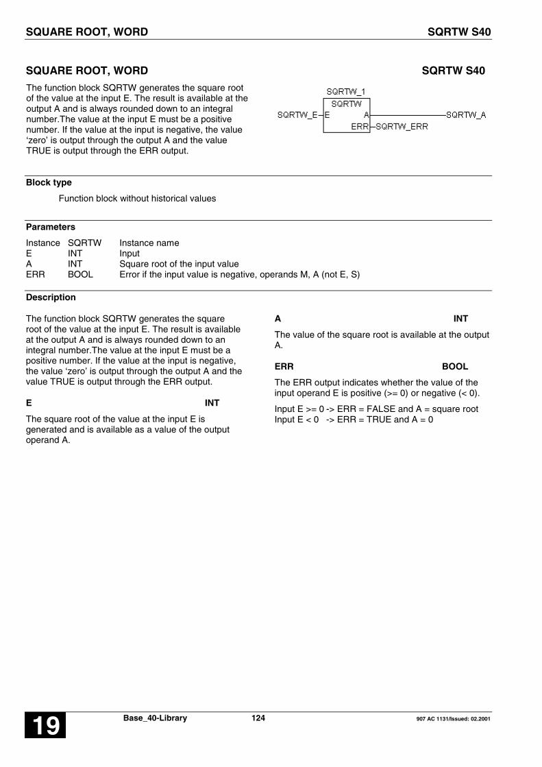
SQUARE ROOT, WORD SQRTW S40
Base_40-Library 124 907 AC 1131/Issued: 02.200119
SQUARE ROOT, WORD SQRTW S40
The function block SQRTW generates the square rootof the value at the input E. The result is available at theoutput A and is always rounded down to an integralnumber.The value at the input E must be a positivenumber. If the value at the input is negative, the value‘zero’ is output through the output A and the valueTRUE is output through the ERR output.
Block type
Function block without historical values
Parameters
Instance SQRTW Instance nameE INT InputA INT Square root of the input valueERR BOOL Error if the input value is negative, operands M, A (not E, S)
Description
The function block SQRTW generates the squareroot of the value at the input E. The result is availableat the output A and is always rounded down to anintegral number.The value at the input E must be apositive number. If the value at the input is negative,the value ‘zero’ is output through the output A and thevalue TRUE is output through the ERR output.
E INT
The square root of the value at the input E isgenerated and is available as a value of the outputoperand A.
A INT
The value of the square root is available at the outputA.
ERR BOOL
The ERR output indicates whether the value of theinput operand E is positive (>= 0) or negative (< 0).
Input E >= 0 -> ERR = FALSE and A = square rootInput E < 0 -> ERR = TRUE and A = 0

SQUARE ROOT, WORD SQRTW S40
907 AC 1131/Issued: 02.2001 125 Base_S40-Library 19
Example
Declaration:
SQRTW_1 : SQRTD;SQRTW_E AT %MW1000.0 : DINT;SQRTW_A AT %MW1000.1 : DINT;SQRTW_ERR AT %MX0.0 : BOOL;
Translation in ABB IL:
!BA 0SQRTK0,0EAERR
FBD: ABB IL of example:
!BA 0SQRTK0,0MW0,0MW0,1M0,0
Function call in IL
CAL SQRTW_1(E := SQRTD_E)
LD SQRTW_1.AST SQRTW_ALD SQRTW_1.ERRST SQRTW_ERR
Function call in ST
SQRTW_1(E := SQRTW_E);
SQRTW_A := SQRTW_1.A;SQRTW_ERR := SQRTW_1.ERR;

SET MEMORY , DOMINATING SR S40
Base_40-Library 126 907 AC 1131/Issued: 02.200119
SET MEMORY , DOMINATING SR S40
A status TRUE at the input SET1 sets the operand Q1to the status TRUE.
A status TRUE at the input RESET resets the operandQ1 to the status FALSE.
=> dominating SET
Block type
Function block without historical values
Parameters
Instance SR Instance nameSET1 BOOL Set inputRESET BOOL Reset inputQ1 BOOL Flip-flop output
Description
A status TRUE at the input SET1 sets the operandQ1 to the status TRUE.
A status TRUE at the input RESET resets theoperand Q1 to the status FALSE.
A simultaneous TRUE status at the inputs SET1 andRESET sets operand Q1 to a status TRUE(dominating set).
A status FALSE at the input SET1 or RESET has noinfluence on the operand Q1.
Example
Declaration:
SR_1 : SR;SR_SET1 AT %MX0.0 : BOOL;SR_RESEET AT %MX0.1 : BOOL;SR_Q1 AT %MX0.2 : BOOL;
Translation in ABB IL:
! RESET=R Q1! SET1=S Q1
FBD: ABB IL of example:
! M0,1=R M0,2! M0,0=S M0,2
Function call in IL
CAL SR_1(SET1 := SR_SET,RESET = SR_RESET)
LD SR_1.Q1ST SR_Q
Function call in ST
SR_1 (SET1 := SR_SET,RESET := SR_RESET);
SR_Q := SR_1.Q1;

SUBTRACTION DOUBLE WORD SUBD S40
907 AC 1131/Issued: 02.2001 127 Base_S40-Library 19
SUBTRACTION DOUBLE WORD SUBD S40
The value of the operand at input E2 is subtracted fromthe value of the operand at input E1 and the result isassigned to the operand at output A.
The result is limited to the maximum or minimum valueof the number range (Number range: -2147483647 …2147483647). If limiting occurred, a TRUE signal isassigned to the binary operand at output Q. If nolimiting occurred, a FALSE signal is assigned to thebinary operand at output Q.
Block type
Function block without historical values
Parameters
Instance SUBD Instance nameE1 DINT MinuendE2 DINT SubtrahendA DINT Result (difference)Q BOOL Result limited
Description
The value of the operand at input E2 is subtracted fromthe value of the operand at input E1 and the result isassigned to the operand at output A.
The result is limited to the maximum or minimum valueof the number range (Number range:-2147483647 … 2147483647). If limiting occurred, aTRUE signal is assigned to the binary operand atoutput Q. If no limiting occurred, a FALSE signal isassigned to the binary operand at output Q.
The inputs and outputs can neither be duplicated nornegated.

SUBTRACTION DOUBLE WORD SUBD S40
Base_40-Library 128 907 AC 1131/Issued: 02.200119
Example
Declaration:
SUBD_1 : SUBD;SUBD_E1 AT %MD2000.0 : DINT;SUBD_E2 AT %MD2000.1 : DINT;SUBD_A AT %MD2000.2 : DINT;SUBD_Q AT %MX0.0 : BOOL;
Translation in ABB IL:
!BA 0SUBDE1E2AQ
FBD: ABB IL of example:
!BA 0SUBDMD0,0MD0,1MD0,2M0,0
Function call in IL
CAL SUBD_1(E1 := SUBD_E1, E2 := SUBD_E2)
LD SUBD1.AST SUBD_ALD SUBD1.QST SUBD_Q
Function call in ST
SUBD_1(E1 := SUBD_E1, E2 := SUBD_E2);
SUBD_A:=SUBD1.A;SUBD_Q:=SUBD1.Q;

TIME WORD CONVERSION TIME_W S40
907 AC 1131/Issued: 02.2001 129 Base_S40-Library 19
TIME WORD CONVERSION TIME_W S40
This functions is used to manage time value withword variables
The time in [ms] TIMEE is converted in hours,minutes, seconds and milliseconds.
Block type
Function block without historical values
Parameters
Instance TIME_W Instance nameTIMEE DINT Time valueH INT Hours valueM INT Minute valueSEC INT Second valueMS INT Millisecond value
Description
This functions is used to manage time value with wordvariables
The Time value TIMEE is converted in hours, minutes,seconds and milliseconds.
TIMEE DINT
The time value is in millisecond.
Value range:0 < TIMEE < 986399999
IF TIMEE is greater than 986399999 then H, M, SEC,MS are set to the maximum value.
IF TIMEE is negative then H, M, SEC, MS are set tozero.
H INT
Output for the hours.
Value range:0 < H < 273
M INT
Output for the minutes.
Value range:0 < M < 59
SEC INT
Output for the seconds.
Value range:0 < SEC < 59
MS INT
Output for the milliseconds.
Value range:0 < MS < 999

TIME WORD CONVERSION TIME_W S40
Base_40-Library 130 907 AC 1131/Issued: 02.200119
Example
Declaration:
TIME_W_1 : TIME_W;TIME_W_TIMEE AT %MD2000.0 : DINT;TIME_W_H AT %MW1000.0 : INT;TIME_W_M AT %MW1000.1 : INT;TIME_W_SEC AT %MW1000.2 : INT;TIME_W_MS AT %MW1000.3 : INT;
Translation in ABB IL:
!BA 0TIME_WHMSECMS
FBD: ABB IL of example:
!BA 0TIME_WMD0,0MW0,0MW0,1MW0,2MW0,3
Function call in IL
CAL TIME_W_1(TIMEE := TIME_W_TIMEE);
LD TIME_W_1.HST TIME_W_HLD TIME_W_1.MST TIME_W_MLD TIME_W_1.SECST TIME_W_SECLD TIME_W_1.MSST TIME_W_MS
Function call in ST
TIME_W_1(TIMEE := TIME_W_TIMEE);
TIME_W_H := TIME_W_1.H;TIME_W_M := TIME_W_1.M;TIME_W_SEC := TIME_W_1.SEC;TIME_W_MS := TIME_W_1.MS;

OFF DELAY TOF S40
907 AC 1131/Issued: 02.2001 131 Base_S40-Library 19
OFF DELAY TOF S40
The TRUE/FALSE edge of the input E is delayed bythe time T at the output A. If the input E returns toTRUE level before expiry of the time T, the output Aretains TRUE level.
Block type
Function block with historical values
Parameters
Instance TOF Instance nameE BOOL Input signalT TIME Preset timeA BOOL Delayed signal, operands M, A (not E, S)ET TIME Time visualization
Description
The TRUE/FALSE edge of the input E is delayed bythe time T at the output A. If the input E returns toTRUE level before expiry of the time T, the output Aretains TRUE level.
The time elapsed can be consulted at the output ETand the preset time value at the input T can bemodified when the timer is running. The preset time isspecified in milliseconds. The time range which canbe specified is : 1 ms ... 24,8 days.
Maximum time offset at the output : < 1 cycle time
Meaningful range for T : > 1 cycle time.
General behavior
� Started timers are processed by the PLC operatingsystem and are therefore completely independent ofprocessing of the PLC program. An appropriatemessage of the operating system is not issued to theaffiliated timer block in the PLC program until thetimer has elapsed.
� Processing of a timer in the PLC operating systemis influenced by the following commands. All runningtimers are stopped and initialized when one of thefollowing actions occurs:
� Abort PLC program� RUN/STOP switch from RUN -> STOP� Warm or cold start

OFF DELAY TOF S40
Base_40-Library 132 907 AC 1131/Issued: 02.200119
Example
Declaration:
TOF_1 : TOF;TOF_IN AT %MX0.0 : BOOL;TOF_PT AT %MD40001.0 : TIME := t#10s; (* 10000 ms *)TOF_Q AT %MX0.1 : BOOL;TOF_ET AT %MD2000.0 : TIME;
Translation in ABB IL:
!BA 0TOFINPTQET
FBD: ABB IL of example:
!BA 0TOFM0,0KD1,0 ; 10000M0,1MD0,0
Function call in IL
CAL TOF_1(E := TOF_E, T := TOF_T)
LD TOF_1.AST TOF_ALD TOF_1.ETST TOF_ET
Function call in ST
TOF_1(E := TOF_E, T := TOF_T);
TOF_A := TOF_1.A;TOF_ET := TOF_1.ET;

ON DELAY TON S40
907 AC 1131/Issued: 02.2001 133 Base_S40-Library 19
ON DELAY TON S40
The FALSE/TRUE edge of the input E is delayed bythe time T at the output A. The output A retains FALSElevel if the input E returns to FALSE level before thetime T has elapsed.
Block type
Function block with historical values
Parameters
Instance TON Instance nameE BOOL Input signalT TIME Preset timeA BOOL Delayed signalET TIME Time visualization
Description
The FALSE/TRUE edge of the input E is delayed bythe time T at the output A. The output A retains 0level if the input E returns to 0 level before the time Thas elapsed.
The time elapsed can be consulted at the output ETand the preset time value at the input T can bemodified when the timer is running. The preset time isspecified in milliseconds. The time range which canbe specified is : 1 ms ... 24.8 days.
Maximum time offset at the output : < 1 cycle time
Meaningful range for T : > 1 cycle time
General behavior
� Started timers are processed by the PLC operatingsystem and are therefore completely independent ofprocessing of the PLC program. An appropriatemessage of the operating system is not issued to theaffiliated timer block in the PLC program until thetimer has elapsed.
� Processing of a timer in the PLC operating systemis influenced by the following commands. All runningtimers are stopped and initialized when one of thefollowing actions occurs:
� Abort PLC program� RUN/STOP switch from RUN -> STOP� Warm or cold start

ON DELAY TON S40
Base_40-Library 134 907 AC 1131/Issued: 02.200119
Example
Declaration:
TON_1 : TON;TON_IN AT %MX0.0 : BOOL;TON_PT AT %MD40001.0 : TIME := t#10s; (* 10000 ms *)TON_Q AT %MX0.1 : BOOL;TON_ET AT %MD2000.0 : TIME;
Translation in ABB IL:
!BA 0TONINPTQET
FBD: ABB IL of example:
!BA 0TONM0,0KD1,0 ; 10000M0,1MD0,0
Function call in IL
CAL TON_1(E := TON_E, T := TON_T)
LD TON_1.AST TON_ALD TON_1.ETST TON_ET
Function call in ST
TON_1(E := TON_E, T := TON_T);
TON_A := TON_1.A;TON_ET := TON_1.ET;

MONOSTABLE ELEMENT « CONSTANT » TP S40
907 AC 1131/Issued: 02.2001 135 Base_S40-Library 19
MONOSTABLE ELEMENT � CONSTANT � TP S40
The FALSE/TRUE edge at the input E produces aFALSE/TRUE edge at the output A. The output A isreset to FALSE level after expiry of the period T.
A second FALSE/TRUE Edge of the input E before thetime T has elapsed is ignored.
Block type
Function block with historical values
Parameters
Instance ASV Instance nameE BOOL Input signalT TIMER Delay timeA BOOL Delayed signalET DINT Time visualization
Description
The FALSE/TRUE edge at the input E produces aFALSE/TRUE edge at the output A. The output A isreset to FALSE level after expiry of the period T.
A second FALSE/TRUE Edge of the input E before thetime T has elapsed is ignored.
The time elapsed can be consulted at the output ETand the preset time value at the input E can bemodified when the timer is running.
The preset time is specified in milliseconds. The timerange which can be specified is : 1 ms ... 24.8 days.
Maximum time offset at the output : < 1 cycle time
Meaningful range for PT : > 1 cycle time.
General behavior
� Started timers are processed by the PLC operatingsystem and are therefore completely independent ofprocessing of the PLC program. An appropriatemessage of the operating system is not issued to theaffiliated timer block in the PLC program until the timerhas elapsed.
� Processing of a timer in the PLC operating system isinfluenced by the following commands. All runningtimers are stopped and initialized when one of thefollowing actions occurs:
� Abort PLC program� RUN/STOP switch from RUN -> STOP� Warm or cold start
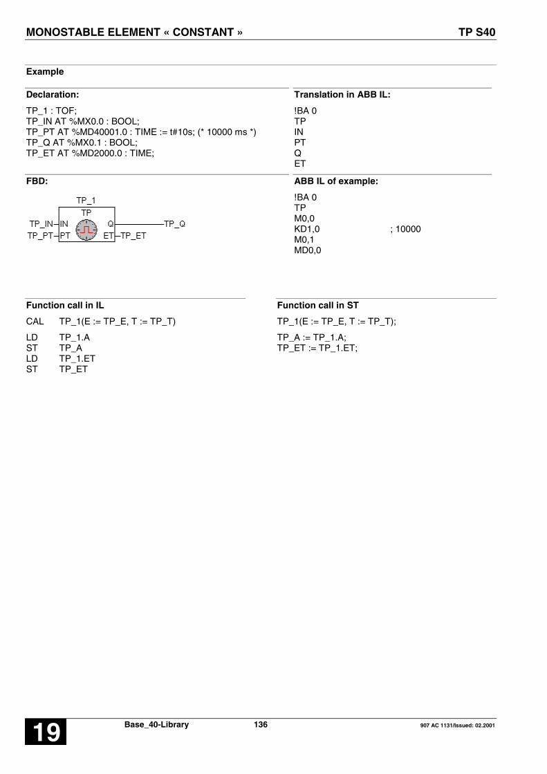
MONOSTABLE ELEMENT « CONSTANT » TP S40
Base_40-Library 136 907 AC 1131/Issued: 02.200119
Example
Declaration:
TP_1 : TOF;TP_IN AT %MX0.0 : BOOL;TP_PT AT %MD40001.0 : TIME := t#10s; (* 10000 ms *)TP_Q AT %MX0.1 : BOOL;TP_ET AT %MD2000.0 : TIME;
Translation in ABB IL:
!BA 0TPINPTQET
FBD: ABB IL of example:
!BA 0TPM0,0KD1,0 ; 10000M0,1MD0,0
Function call in IL
CAL TP_1(E := TP_E, T := TP_T)
LD TP_1.AST TP_ALD TP_1.ETST TP_ET
Function call in ST
TP_1(E := TP_E, T := TP_T);
TP_A := TP_1.A;TP_ET := TP_1.ET;

DISPLAY AND SET CLOCK UHR S40
907 AC 1131/Issued: 02.2001 137 Base_S40-Library 19
DISPLAY AND SET CLOCK UHR S40
This function block allows to set and displaythe current time and date.
Block type
Function block with historical values
Parameters
Instance UHR Instance nameFREI BOOL Enable block processingSET BOOL FALSE/TRUE edge sets the time and dateESEC INT Set input for secondsEMIN INT Set input for minutesEH INT Set input for hoursETAG INT Set input for daysEMON INT Set input for monthsEJHR INT Set input for yearsEWO INT Set input for weekdaysAKT BOOL Topicality (usefulness) of the data at the outputsERR INT Error identifierASEC INT Output secondsAMIN INT Output minutesAH INT Output hoursATAG INT Output daysAMON INT Output monthsAJHR INT Output yearsAWO INT Output weekday no.
Description
This function block allows to set and display thecurrent time and date.
The inputs and outputs can neither be duplicated norinverted nor negated.
The clock is set by means of the set inputs for thetime and date. The values present at the set inputsare adopted with the occurrence of a FALSE/TRUEedge at input SET. As long as a TRUE signal ispresent at the FREI input, the current date and timeare indicated at the block’s outputs.
FREI BOOLEnabling the block
FREI = FALSE:The block is not processed. The AKT and ERRoutputs are set to FALSE or 0. The time and dateoutputs are no longer changed by the block.
FREI = TRUE:Block is processed

DISPLAY AND SET CLOCK UHR S40
Base_40-Library 138 907 AC 1131/Issued: 02.200119
SET BOOL
FALSE/TRUE edge:The clock is set to the values present at the time anddate inputs.
During the setting procedure the time and date at theblock outputs are invalid (output AKT = FALSE).
Set inputs for date and time
In the event of a FALSE/TRUE edge at input SET,the clock is set to the values present at the set inputs.If the specified set values are inadmissible, the AKToutput is set to FALSE and an error messageappears at the ERR output. In this case the valuespresent at the time and date outputs are invalid. Theclock has to be set again.
ESEC INTSet input for seconds.Value range: 0 … 59.
EMIN INTSet input for minutes.Value range: 0 … 59.
EH INTSet input for hours.
The clock operates in 24 hour mode, i.e. it changesfrom 23:59:59 h to 0:0:0 h.
Value range: 0 … 23.
ETAG INTSet input for days (which day of the month).
The clock knows the number of days depending onthe months and leap years. For the clock, a leap yearexists when the year number is an integral multiple of4. The maximum value for the days (28, 29, 30, 31)depends on the month.
Value range: 1…28, 29, 30, 31.
EMON INTSet input for months.Value range: 1 … 12.
EJHR INTSet input for years.The clock only indicates the years and decades.Value range: 0 … 99.
EWO INT
Set input for the number of the weekday.
This input specifies on which day of the week theinput is made. That is to say, it is possible todetermine which day of the week the day with thenumber 1 is to be (e. g. Sunday or Monday).
Value range: 1 … 7.
Example:The clock is set on Friday, 01.07.88. If the value 6 isentered for the week day number, Friday is now the6th day of the week and Sunday is defined as the 1stday of the week.
AKT BOOL
Indication of the topicality (usefulness) of the outputs.
AKT is TRUE if:
– The date and time outputs were updated in thecurrent cycle.
– The values at the outputs are consistent, i.e. noneof the values at the date or time outputs haschanged during updating. They all originate fromthe same clock pulse.
– The clock was set correctly.
AKT = TRUE → ERR = 0:Date/time are valid
AKT = FALSE → ERR > 0:Date/time are invalidThe reason is displayed at output ERR as an erroridentifier.
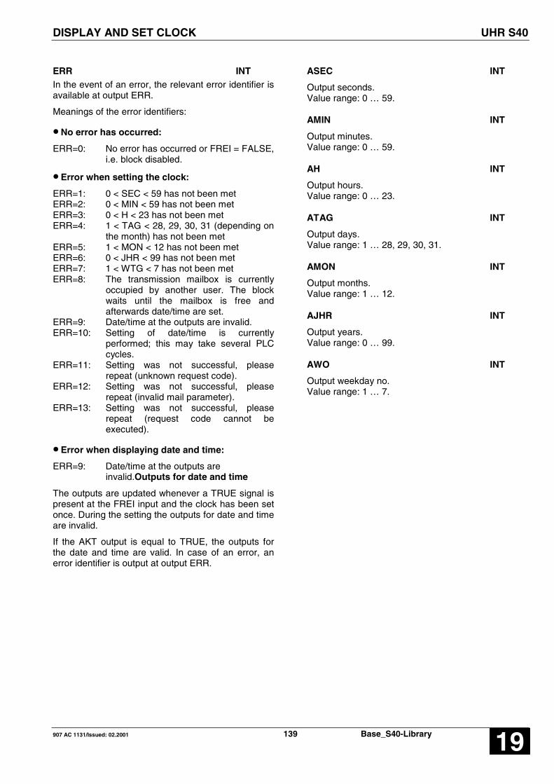
DISPLAY AND SET CLOCK UHR S40
907 AC 1131/Issued: 02.2001 139 Base_S40-Library 19
ERR INTIn the event of an error, the relevant error identifier isavailable at output ERR.
Meanings of the error identifiers:
• No error has occurred:
ERR=0: No error has occurred or FREI = FALSE,i.e. block disabled.
• Error when setting the clock:
ERR=1: 0 < SEC < 59 has not been metERR=2: 0 < MIN < 59 has not been metERR=3: 0 < H < 23 has not been metERR=4: 1 < TAG < 28, 29, 30, 31 (depending on
the month) has not been metERR=5: 1 < MON < 12 has not been metERR=6: 0 < JHR < 99 has not been metERR=7: 1 < WTG < 7 has not been metERR=8: The transmission mailbox is currently
occupied by another user. The blockwaits until the mailbox is free andafterwards date/time are set.
ERR=9: Date/time at the outputs are invalid.ERR=10: Setting of date/time is currently
performed; this may take several PLCcycles.
ERR=11: Setting was not successful, pleaserepeat (unknown request code).
ERR=12: Setting was not successful, pleaserepeat (invalid mail parameter).
ERR=13: Setting was not successful, pleaserepeat (request code cannot beexecuted).
• Error when displaying date and time:
ERR=9: Date/time at the outputs areinvalid.Outputs for date and time
The outputs are updated whenever a TRUE signal ispresent at the FREI input and the clock has been setonce. During the setting the outputs for date and timeare invalid.
If the AKT output is equal to TRUE, the outputs forthe date and time are valid. In case of an error, anerror identifier is output at output ERR.
ASEC INT
Output seconds.Value range: 0 … 59.
AMIN INT
Output minutes.Value range: 0 … 59.
AH INT
Output hours.Value range: 0 … 23.
ATAG INT
Output days.Value range: 1 … 28, 29, 30, 31.
AMON INT
Output months.Value range: 1 … 12.
AJHR INT
Output years.Value range: 0 … 99.
AWO INT
Output weekday no.Value range: 1 … 7.

DISPLAY AND SET CLOCK UHR S40
Base_40-Library 140 907 AC 1131/Issued: 02.200119
Example
Declaration:
UHR_1 : UHR;UHR_FREI AT %MX0.0 : BOOL;UHR_SET AT %MX0.1 : BOOL;UHR_ESEC AT %MW1000.0 : INT;UHR_EMIN AT %MW1000.1 : INT;UHR_EH AT %MW1000.2 : INT;UHR_ETAG AT %MW1000.3 : INT;UHR_EMON AT %MW1000.4 : INT;UHR_EJHR AT %MW1000.5 : INT;UHR_EWO AT %MW1000.6 : INT;UHR_AKT AT %MX0.2 : BOOL;UHR_ERR AT MW1000.7 : INT;UHR_ASEC AT MW1000.8 : INT;UHR_AMIN AT MW1000.9 : INT;UHR_AH AT MW1000.10 : INT;UHR_ATAG AT MW1000.11 : INT;UHR_AMON AT MW1000.12 : INT;UHR_AJHR AT MW1000.13 : INT;UHR_AWO AT MW1000.14 : INT;
Translation in ABB IL:
!BA 0UHRSETESECEMINEHETAGEMONEJHREWOAKTERRASECAMINAHATAGAMONAJHRAWO
FBD: ABB IL of example:
!BA 0UHRM0,0M0,1MW1,0MW1,1MW1,2MW1,3MW1,4MW1,5MW1,6M0,2MW1,7MW1,8MW1,9MW1,10MW1,11MW1,12MW1,13MW1,14

DISPLAY AND SET CLOCK UHR S40
907 AC 1131/Issued: 02.2001 141 Base_S40-Library 19
Function call in IL
CAL UHR_1( FREI := UHR_FREI,SET := UHR_SET,ESEC := UHR_ESEC,EMIN := UHR_EMIN,EH := UHR_EH,ETAG := UHR_ETAG,EMON := UHR_EMON,EJHR := UHR_EJHR,EWO := UHR_EWO)
LD UHR_1.ERRST UHR_ERRLD UHR_1.ASECST UHR_ASECLD UHR_1.AMINST UHR_AMINLD UHR_1.AHST UHR_AHLD UHR_1.ATAGST UHR_ATAGLD UHR_1.AMONST UHR_AMONLD UHR_1.AJHRST UHR_AJHRLD UHR_1.AWOST UHR_AWOLD UHR_1.AKTST UHR_AKT
Note: In IL, the function call has to be performed inone line.
Function call in ST
UHR_1 FREI := UHR_FREI,SET := UHR_SET,ESEC := UHR_ESEC,EMIN := UHR_EMIN,EH := UHR_EH,ETAG := UHR_ETAG,EMON := UHR_EMON,EJHR := UHR_EJHR,EWO := UHR_EWO);
UHR_ERR := UHR_1.ERR;UHR_ASEC := UHR_1.ASEC;UHR_AMIN := UHR_1.AMIN;UHR_AH := UHR_1.AH;UHR_ATAG := UHR_1.ATAG;UHR_AMON := UHR_1.AMON;UHR_AJHR := UHR_1.AJHR;UHR_AWO := UHR_1.AWO;UHR_AKT := UHR_1.AKT;

UNPACKING A WORD INTO BINARY VARIABLES UNPACK(4,..) S40
Base_40-Library 142 907 AC 1131/Issued: 02.200119
UNPACKING A WORD INTO BINARY VARIABLES UNPACK(4,..) S40
This function block unpacks the word variable atinput E. Each bit of the input variable is assigned toone binary variable each (B0 ... B15) at the output.
UNPACK4 – max. 4 output variablesUNPACK8 – max. 8 output variablesUNPACK16 – max. 16 output variables
Block type
Function block without historical values
Parameters
Instance UNPACK Instance nameE INT Word variable to be unpackedN INT Number of bitB0..B15 BOOL Binary output variable
Description
This function block unpacks the word variable at inputE. Each bit of the input variable is assigned to onebinary variable each (B0 ... Bn-1) at the output.
E INT
The variable to be unpacked is specified at input E.Each bit (bit0 ... bit15) of this input variable is assignedto the assigned output variable (B0 ... Bn-1).
B0…B15 BOOL
The assigned bits of the variable at input E areassigned to the binary outputs B0 ... B15.
Assignment:
Input variable Bit0 → B0Input variable Bit1 → B1
. . .
. . .Input variable Bit15 → B15

UNPACKING A WORD INTO BINARY VARIABLES UNPACK(4,..) S40
907 AC 1131/Issued: 02.2001 143 Base_S40-Library 19
Example
Declaration:
UNPACK_4: UNPACK4;UNPACK_E AT %MW1001.0: INT;UNPACK_B0 AT %MX1.0: BOOL;UNPACK_B1 AT %MX1.1: BOOL;UNPACK_B2 AT %MX1.2: BOOL;UNPACK_B3 AT %MX1.3: BOOL;
Translation in ABB IL:
!BA 0UNPACKE#nB0B1B2B3
FBD: ABB IL of example:
!BA 0UNPACKM0,0#4M1,0M1,1M1,2M1,3
Function call in IL
CAL UNPACK_4(E := UNPACK_E,n := 4)
LD UNPACK_4.B0ST UNPACK_B0LD UNPACK_4.B1ST UNPACK_B1LD UNPACK_4.B2ST UNPACK_B2LD UNPACK_4.B3ST UNPACK_B3
Function call in ST
UNPACK_4 (E := UNPACK_E,n := 4);
UNPACK_B0 :=UNPACK_4.B0UNPACK_B1 :=UNPACK_4.B1UNPACK_B2 :=UNPACK_4.B2UNPACK_B3 :=UNPACK_4.B3;

UP-DOWN COUNTER VRZ S40
Base_40-Library 144 907 AC 1131/Issued: 02.200119
UP-DOWN COUNTER VRZ S40
This function block is used to count pulses. Duringcounting, the positive edge of the pulse is evaluated ineach case. The counter is capable of counting up anddown and the counting increment can be specified. Itis possible to preset the counter content to anintermediate value.
Block type
Function block with historical values
Parameters
Instance VRZ Instance nameFREI BOOL Enabling of the block processingZV BOOL Pulse input, up countingZR BOOL Pulse input, down countingDIFF INT Counter content change per positive edge (increment)SET BOOL Set counter to an intermediate valueZW INT Intermediate valueRESET BOOL Reset counterA INT Output for counter content
Description
This function block is used to count pulses. Duringcounting, the positive edge of the pulse is evaluatedin each case. The counter is capable of counting upand down and the counting increment can bespecified. It is possible to preset the counter contentto an intermediate value.
FREI BOOL
Counting is enabled or disabled by means of theFREI input.
The following applies:
FREI = FALSE → Counting disabledFREI = TRUE → Counting enabled
ZV BOOL
Each positive edge (FALSE → TRUE edge) at theinput ZV increases the current counter content by theincrement specified at input DIFF.
ZR BOOL
Each positive edge (FALSE → TRUE edge) at theinput ZR decreases the current counter content bythe increment specified at input DIFF.
DIFF INT
The increment for the counting operation is specifiedat input DIFF. The increment is the value by whichthe counter is changed at the input ZV or ZR witheach positive edge.
SET BOOLBy means of a TRUE signal at input SET, the countercontent is set to the value specified at input ZW.Counting is blocked as long as a TRUE signal ispresent at input SET. Setting is also effective when aTRUE signal is present at input FREI.
ZW INTThe value to which the counter content is set by aTRUE signal at input SET is specified at the inputZW.
RESET BOOLA TRUE signal at input RESET sets the countercontent to the value 0. The reset input RES has thehighest priority of all inputs.

UP-DOWN COUNTER VRZ S40
907 AC 1131/Issued: 02.2001 145 Base_S40-Library 19
A INTThe current counter content is available at output A.
If the counter reaches the positive or negative limit ofthe number range, the counter is limited to this value.The inputs and the output can neither be duplicatednor negated/inverted
Example
Declaration:
VRZ_1 : VRZ;VRZ_FREI AT %MX0.0 : BOOL;VRZ_ZV AT %MX0.1 : BOOL;VRZ_ZR AT %MX0.2 : BOOL;VRZ_DIFF AT %MW1000.0 : INT;VRZ_SET AT %MX0.3 : BOOL;VRZ_ZW AT %MW1000.1 : INT;VRZ_RESET AT %MX0.4 : BOOL;VRZ_A AT %MW1000.2 : INT;
Translation in ABB IL:
!BA 0VRZRESETDIFFSETZWFREIZVZRA
FBD: ABB IL of example:
!BA 0VRZM0,4MW0,0M0,3MW0,1M0,0M0,1MW0,2
Function call in IL
CAL VRZ_1(FREI := VRZ_FREI,ZV := VRZ_ZV,ZR := VRZ_ZR,DIFF := VRZ_DIFF,SET := VRZ_SET,ZW := VRZ_ZW,RESET := VRZ_RESET)
LD VRZ_1.AST VRZ_A
Function call in ST
VRZ_1(FREI := VRZ_FREI, ZV := VRZ_ZV,ZR := VRZ_ZR, DIFF := VRZ_DIFF,SET := VRZ_SET, ZW := VRZ_ZW,RESET := VRZ_RESET);
VRZ_A:=VRZ_1.A;

INTERRUPTION TASK VALIDATION VTASK S40
Base_40-Library 146 907 AC 1131/Issued: 02.200119
INTERRUPTION TASK VALIDATION VTASK S40
Enable or disable (interrupt) task routine.
Block type
Function block without historical values
Parameters
Instance VTASK Instance nameEne BOOL Interrupt validationINTNUM INT Interrupt number
Description
The VTASK function validates the execution of aninterruption whose name is specified in NAMEvariable
In function block diagram, the block has the name ofthe interruption.
In instruction list, the function is VTASK with NAMEand EN as parameters.
Example
Declaration:
VTASK_1 : VTASK;VTASK_EN AT %MX0.0 : BOOL;
Translation in ABB IL:
!BA 0VTASKEN#INTNUM
FBD:
Note:The Task for INT 1 must have the name INT1,for INT 2 – IN2 and for cycle task 10 – INT10_cycle time [ms]
ABB IL of example:
!BA 0VTASKM0,0#1...!PE (* Programmende *)!BA 0TASK#1#1... (* Code der Interrupttask *)RETNOP
Function call in IL
CAL VTASK_1(enable := VTASK_enable,N := VTASK_N )
Function call in ST
VTASK_1 (enable := VTASK_enable,N := VTASK_N );

AND COMBINATION, WORD WAND S40
907 AC 1131/Issued: 02.2001 147 Base_S40-Library 19
AND COMBINATION, WORD WAND S40
This function block generates, bit-by-bit, the ANDcombination of the operands present at the inputs E1and E2. The result is allocated to the operand at theoutput.
Block type
Function
Parameters
E1 INT Operand 1E2 INT Operand 2A INT Result of the AND combination
Description
This function block generates, bit-by-bit, the ANDcombination of the operands present at the inputs E1and E2. The result is allocated to the operand at theoutput.
The inputs and outputs can neither be duplicated nornegated.
Example
Declaration:
WAND_E1 AT %MW1000.0 : INT;WAND_E2 AT %MW1000.1 : INT;WAND_A AT %MW1000.2 : INT;
Translation in ABB IL:
!BA 0WANDE1E2A
FBD: ABB IL of example:
!BA 0WANDMW0,0MW0,1MW0,2
Function call in IL
LD WAND_E1WAND WAND_E2ST WAND_A
Function call in ST
WAND_A := WAND(E1 := WAND_E1,E2 := WAND_E2);

WORD TIME CONVERSION W_TIME S40
Base_40-Library 148 907 AC 1131/Issued: 02.200119
WORD TIME CONVERSION W_TIME S40
This functions is used to set a TIME value throughwords.
The words values are converted in a double wordfor timer functions.
Block type
Function block without historical values
Parameters
Instance W_TIME Instance nameH INT Hour valueM INT Minute valueSEC INT Second valueMS INT Millisecond valueTIMEE DINT Time value
Description
This functions is used to set a time value throughwords.
The words values are converted in a double word fortimer functions.
The time value is in millisecond.
H INT
Input for the hours.
Value range:0 < H < 273
M INT
Input for the minutes.
Value range:0 < M < 32767
SEC INT
Input for the seconds.
Value range:0 < SEC < 32767
MS INT
Input for the milliseconds.
Value range:0 < MS < 32767
TIMEE DINT
Output for the converted time value is in milliseconds.
Value range:0 < TIMEE < 986399999
If one parameter is set to a negative value, the valueused for the internal calculation is 0.

WORD TIME CONVERSION W_TIME S40
907 AC 1131/Issued: 02.2001 149 Base_S40-Library 19
Example
Declaration:
W_TIME_H AT %MW1000.0 : INT;W_TIME_M AT %MW1000.1 : INT;W_TIME_SEC AT %MW1000.2 : INT;W_TIME_MS AT %MW1000.3 : INT;W_TIME_TIMEE AT %MD2000.0 : DINT;
Translation in ABB IL:
!BA 0W_TIMEHMSECMSTIMEE
FBD: ABB IL of example:
!BA 0W_TIMEMW0,0MW0,1MW0,2MW0,3MD0,0
Function call in IL
CAL W_TIME1( H := W_TIME_H,M := W_TIME_M,SEC := W_TIME_SEC,MS := W_TIME_MS)
LD W_TIME1.TIMEEST W_TIME_TIMEE
Function call in ST
W_TIME1 ( H := W_TIME_H,M := W_TIME_M,SEC := W_TIME_SEC,MS := W_TIME_MS);
W_TIME_TIMEE := W_TIME1.TIMEE;

WORD TO DOUBLE WORD CONVERSION WDW S40
Base_40-Library 150 907 AC 1131/Issued: 02.200119
WORD TO DOUBLE WORD CONVERSION WDW S40
The value of the word operand at input E is convertedto a double word variable and the result is assigned tothe double word operand at output A.
Block type
Function
Parameters
E INT Word variable to be convertedA DINT Result of the conversion, double word variable
Description
The value of the word operand at input E is convertedto a double word variable and the result is assigned tothe double word operand at output A.
Value range for E1:8000H < E1 < 7FFFH
-32768 < E1 < 32767
The input and the output can neither be duplicated nornegated.
Example
Declaration:
WDW_E AT %MW1000.0 : INT;WDW_A AT %MD2000.0 : DINT;
Translation in ABB IL:
!BA 0WDWEA
FBD: ABB IL of example:
!BA 0WDWMW0,0MD0,0
Function call in IL
LD WDW_EWDWST WDW_DW
Function call in ST
WDW_DW := WDW(WDW_E);

READ WORD WITH ENABLING WOL S40
907 AC 1131/Issued: 02.2001 151 Base_S40-Library 19
READ WORD WITH ENABLING WOL S40
If there is a TRUE signal at input FREI, the value of thespecified physical address is read and assigned to theoperand at output A.
Block type
Function
Parameters
FREI BOOL Enabling the blockOFF INT Offset address of the memory locationSEG INT Segment address of the memory locationA INT Output to which the value read is assigned
Description
If there is a TRUE signal at input FREI, the value of thespecified physical address is read and assigned to theoperand at output A.
No reading and no assignment is performed, if there isa FALSE signal at input FREI.
The inputs and the output can neither be duplicated nornegated.
FREI BOOL
Processing of the block is enabled or disabled with theoperand at input FREI.
The following applies:
FREI = FALSE → Processing disabledFREI = TRUE → Processing enabled
OFF INT
The offset address to be read is specified at input OFF.This is specified as 16 bit address.
SEG INT
The segment address to be read is specified at inputADRESSE. This is specified as 16 bit address.
A INT
The value read is assigned to the operand at output A.

READ WORD WITH ENABLING WOL S40
Base_40-Library 152 907 AC 1131/Issued: 02.200119
Example
Declaration:
WOL_FREI AT %MX0.0 : BOOL;WOL_A AT %MW1000.0 : INT
Translation in ABB IL:
!BA 0WOLFREIOFFSEG
FBD: ABB IL of example:
!BA 0WOLM0,0#0#H197C
Function call in IL
LD WOL_FREIWOL WOL_OFF, WOL_ADRST WOL_A
Function call in ST
WOL_A := WOL(WOL_FREI,WOL_OFF,WOL_SEG);

OR COMBINATION, WORD WOR S40
907 AC 1131/Issued: 02.2001 153 Base_S40-Library 19
OR COMBINATION, WORD WOR S40
This function block generates, bit-by-bit, the ORcombination of the operands present at the inputs E1and E2. The result is allocated to the operand at theoutput.
Block type
Function
Parameters
E1 INT Operand 1E2 INT Operand 2A INT Result of the OR combination
Description
This function block generates, bit-by-bit, the ORcombination of the operands present at the inputs E1and E2. The result is allocated to the operand at theoutput.
The inputs and outputs can neither be duplicated nornegated.
Example
Declaration:
WOR_E1 AT %MW1000.0 : INT;WOR_E2 AT %MW1000.1 : INT;WOR_A AT %MW1000.2 : INT;
Translation in ABB IL:
!BA 0WORE1E2A
FBD: ABB IL of example:
!BA 0WORMW0,0MW0,1MW0,2
Function call in IL
LD WOR_E1WOR WOR_E2ST WOR_A
Function call in ST
WOR_A := WOR(E1 := WOR_E1,E2 := WOR_E2);

XOR COMBINATION, WORD WXOR S40
Base_40-Library 154 907 AC 1131/Issued: 02.200119
XOR COMBINATION, WORD WXOR S40
This function block generates, bit-by-bit, the XORcombination of the operands present at the inputs E1and E2. The result is allocated to the operand at theoutput.
Block type
Function
Parameters
E1 INT Operand 1E2 INT Operand 2A INT Result of the XOR combination
Description
This function block generates, bit-by-bit, the XORcombination of the operands present at the inputs E1and E2. The result is allocated to the operand at theoutput.
The inputs and outputs can neither be duplicated nornegated.
Example
Declaration:
WXOR_E1 AT %MW1000.0 : INT;WXOR_E2 AT %MW1000.1 : INT;WXOR_A AT %MW1000.2 : INT;
Translation in ABB IL:
!BA 0WXORE1E2A
FBD: ABB IL of example:
!BA 0WXORMW0,0MW0,1MW0,2
Function call in IL
LD WXOR_E1WXOR WXOR_E2ST WXOR_A
Function call in ST
WXOR_A := WXOR(E1 := WXOR_E1,E2 := WXOR_E2);

907 AC 1131/Issued: 02.2001 155 Base_S40-Library 19
Glossary
BOOLVariables of the type BOOL can have the values TRUE and FALSE. For this, 8 bit memory space are reserved.
DINTDINT belongs to the integer data types.
The different numerical types are responsible for a different numerical range. For integer data types the followingrange limits are valid:
Type Lower limit Upper limit Memory spaceDINT: -2147483648 2147483647 32 bit
Due to this, it is possible that information are lost during the conversion of greater data types to smaller data types.
DWORDDWORD belongs to the integer data types.
The different numerical types are responsible for a different numerical range. For integer data types the followingrange limits are valid:
Type Lower limit Upper limit Memory spaceDWORD 0 4294967295 32 bit
Due to this, it is possible that information are lost during the conversion of greater data types to smaller data types.
INTINT belongs to the integer data types.
The different numerical types are responsible for a different numerical range. For integer data types the followingrange limits are valid:
Type Lower limit Upper limit Memory spaceINT: -32768 32767 16 bit
Due to this, it is possible that information are lost during the conversion of greater data types to smaller data types.

Base_40-Library 156 907 AC 1131/Issued: 02.200119
WORDWORD belongs to the integer data types.
The different numerical types are responsible for a different numerical range. For integer data types the followingrange limits are valid:
Type Lower limit Upper limit Memory spaceWORD 0 65535 16 bit
Due to this, it is possible that information are lost during the conversion of greater data types to smaller data types.
FunctionsFunctions are subroutines which have multiple input parameters and return exactly one result element. Thereturned result can be of an elementary or a derived data type.
For the same input parameters, functions always return the same result (they do not have an internal memory).
Therefore, the following rules can derived:
• Within functions, global variables can neither be read nor written.• Within functions, it is not allowed to read or write absolute operands.• Within functions, it is not allowed to call function blocks.
Function blocksFunction blocks are subroutines which can have as much inputs, outputs and internal variables as required. Theyare called by a program or by another function block.
As they can be used several times (with different data records), function blocks (code and interface) can beconsidered as type. When assigning an individual data record (declaration) to the function block, a function blockinstance is generated.
In contrast to functions, function blocks can contain statically local data which are saved from one call to the next.This allows for example to realize counters which may not forget their counter value. I.e. function blocks can havean internal memory.
Functions and function blocks differ in two essential points:
• A function block has multiple output parameters. A function has maximally one output parameter. Note that theoutput parameters of functions and function blocks differ syntactically.
• In contrast to a function, a function block can have an internal memory.
For all ABB function blocks it has to be observed that instance names may not be defined several times if differentdata sets should be called.
Example:Name TypeVRZ1 VRZVRZ2 VRZ. .

907 AC 1131/Issued: 02.2001 157 Base_S40-Library 19
Index
A
ADDD S40 8
ASV S40 10
AWT S40 12
AWTB S40 13
B
Base S40
ADDD 8
AWT 12
AWTB 13
BCDDUAL 14
BEG 17
BMELD 19
CONFIO 22
COPY 25
CS31CO 27
CS31QU 35
CTU 37
CTUH 39
DIN 42
DIVD 44
DOUT 46
DRUCK 48
DUALBCD 52
DWAND 54
DWOR 55
DWW 56
DWXOR 57
EMAS 58
ESV 62
FKG 64
I_MINUS 66
I_PLUS 68
IDLB 70
IDLM 72
IDSB 74
IDSM 76
LIZU 78
MOA 80
MOAT 82
MODMAST_B/W 84
MOK 92
MUL2N 94
MULD 96
MULDI 98
NEGW 100
NPULSE 101
PACK 103
PDM 105
PI 107
PIDT1 112
RS 118
SINIT 119
SQRTD 122
SQRTW 124
SR 126
SUBD 127
TIME_W 129
TOF 131
TON 133
TP 135
UHR 137
UNPACK 142
VRZ 144
VTASK 146
W_TIME 148
WAND 147
WDW 150
WOL 151
WOR 153

Base_40-Library 158 907 AC 1131/Issued: 02.200119
WXOR 154
BCDDUAL S40 14
BEG S40 17
BMELD S40 19
C
CONFIO S40 22
COPY S40 25
CS31CO S40 27
CS31QU S40 35
CTU S40 37
CTUH S40 39
D
DIN S40 42
DIVD S40 44
DOUT S40 46
DRUCK S40 48
DUALBCD S40 52
DWAND S40 54
DWOR S40 55
DWW S40 56
DWXOR S40 57
E
EMAS S40 58
ESV S40 62
F
FKG S40 64
Function blocks 3
Functions 3
I
I_MINUS S40 66
I_PLUS S40 68
IDLB S40 70
IDLM S40 72
IDSB S40 74
IDSM S40 76
L
LIZU S40 78
M
MOA S40 80
MOAT S40 82
MODMAST_B/W S40 84
MOK S40 92
MUL2N S40 94
MULD S40 96
MULDI S40 98
N
NEGW S40 100
NPULSE S40 101
P
PACK S40 103
PDM S40 105
PI S40 107
PIDT1 S40 112
R
RS S40 118
S
SINIT S40 119
SQRTD S40 122
SQRTW S40 124
SR S40 126
SUBD S40 127
T
TIME_W S40 129
TOF S40 131
TON S40 133
TP S40 135

907 AC 1131/Issued: 02.2001 159 Base_S40-Library 19
U
UHR S40 137
UNPACK S40 142
V
VRZ S40 144
VTASK S40 146
W
W_TIME S40 148
WAND S40 147
WDW S40 150
WOL S40 151
WOR S40 153
WXOR S40 154

ABB STOTZ-KONTAKT GmbH ABB ControlEppelheimer Straße 82 Postfach 101680 10, rue Ampère Z.I. - B.P. 11469123 Heidelberg 69006 Heidelberg F-69685 Chassieu cedex, FranceGermany Germany
Telephone +49 6221 701-0 Telephone +33 (0) 4 7222 1722Telefax +49 6221 701-1111 Telefax +33 (0) 4 7222 1935E-Mail [email protected] E-MailInternet http://www.abb.de/stotz-kontakt Internet http://www.abb.com/lowvoltage
Man
ual N
o.:
2CD
C 1
20 0
69 M
020
2