Embed Size (px)
Citation preview

2018 / 02
TOX®-Powerpackage X-KT-SystemThe pneumohydraulic split system
Data sheet 10.05
TOX® PressOTechnikriedstrasse 4D-88250 Weingarten
Find your local contact at:www.tox-pressotechnik.com
Gmbh &co. kG

2
10
3 7 6 58941112
60212
TB 10.05_201802.enwww.tox-pressotechnik.com
The TOX®-Powerpackage X-kT- system consists of the pressure intensifier X-es and one or more drive cylinders. Depending on the required press force, dimensions and cycle-time each system is configured individually to customers needs. Drive cylinders can be selected from either the TOX®-hydraulic cylinder hZL or the pneumohydraulic TOX®-Working cylinder X-AT.
Advantages of the X-KT-System:
+ Press forces 2 – 1700 kn + Long power strokes + compact measurements + easy controls + Use up to 6 drive cylinders per intensifier + Low noise + connection via TOX®-hydrosplit coupling + easy colour-guided pneumatic plug-in-system
TOX®-Powerpackage X-KT-Systemcustomized to individual needs
The TOX®-Pressure intensifier X-es is connected to the drive cylinders via hydraulic hoses and TOX®-hydrosplit couplings. The changeover from fast approach stroke to power stroke is perfor-med automatically according to the dynamic pressure principle. The speed of the changeover can be regulated via a control throttle. The unit is controlled by a 4/2 or 5/2-way valve.
As standard, the pressure intensi-fiers are designed for air pressure of 6 bar. Other air pressures or combinations on request.
The TOX®-Pressure intensifier X-es features:
+ Absolute air-oil separation + integrated bypass for reliable operation of the system + ring reservoir for significantly reduced overall length + can be mounted in any orientation + Air spring included + simple pneumatic controls like for any double acting pneumatic cylinder + closed oil system + All X-kT-systems with fast ap-proach support
TOX®-Pressure Intensifier X-ES with fast approach stroke function
Press with
TOX®-Powerpackage
X-KT-System: 1 pressure
intensifier and 6 drive
cylinders.
1 high pressure connection 2 high pressure measuring
and control connection 3 Oil filling nipple 4 Bleed plate 5 Air connection fast approach
stroke 6 Air connection return stroke 7 return stroke air hose 8 Oil level indicator 9 Patented anti-overfill device 10 intensifier piston 11 hydrosplit coupling 12 Fast approach stroke hose
(only for X-AT)602 Power stroke valve632 Valve block ZVX
3
2 63
154
431
8 10 11 8 6 12 95
7 2
TB 10.05_201802.en www.tox-pressotechnik.com
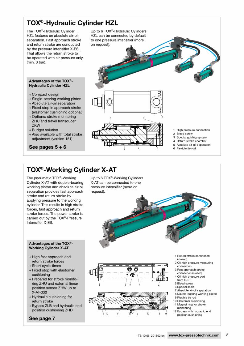
TOX®-Hydraulic Cylinder HZLThe TOX®-hydraulic cylinder hZL features an absolute air-oil separation. Fast approach stroke and return stroke are conducted by the pressure intensifier X-es. That allows the return stroke to be operated with air pressure only (min. 3 bar).
1 high pressure connection2 Bleed screw3 special guiding system4 return stroke chamber5 Absolute air-oil separation 6 Flexible tie rod
Advantages of the TOX®-Hydraulic Cylinder HZL
+ compact design + single-bearing working piston + Absolute air-oil separation + Fixed stop in approach stroke (elastomer cushioning optional) + Options: stroke monitoring ZhU and travel transducer ZkW + Budget solution + Also available with total stroke adjustment (version 151)
See pages 5 + 6
TOX®-Working Cylinder X-ATThe pneumatic TOX®-Working cylinder X-AT with double-bearing working piston and absolute air-oil separation provides fast approach stroke and return stroke by applying pressure to the working cylinder. This results in high stroke forces, fast approach and return stroke forces. The power stroke is carried out by the TOX®-Pressure intensifier X-es.
Advantages of the TOX®-Working Cylinder X-AT
+ high fast approach and return stroke forces + short cycle-times + Fixed stop with elastomer cushioning + Prepared for stroke monito-ring ZhU and external linear position sensor ZhW up to X-AT-030 + hydraulic cushioning for return stroke + Bypass ZLB and hydraulic end position cushioning ZhD
See page 7
Up to 6 TOX®-hydraulic cylinders hZL can be connected by default to one pressure intensifier (more on request).
Up to 6 TOX®-Working cylinders X-AT can be connected to one pressure intensifier (more on request).
1 return stroke connection (closed)
2 Oil high pressure measuring connection
3 Fast approach stroke connection (closed)
4 Oil high pressure port from X-es
5 Bleed screw 6 special seals 7 Absolute air-oil separation 8 Double-bearing working piston 9 Flexible tie rod10 elastomer cushioning11 Magnet ring for stroke
monitoring12 Bypass with hydraulic end
position cushioning

4 TB 10.05_201802.enwww.tox-pressotechnik.com
Design of a TOX®-X-KT-System example calculation of a combination of TOX®-Pressure intensifier X-es and TOX®-hydraulic cylinder hZL:
To figure out what combination of TOX®-Pressure intensifier X-es and TOX®-Working cylinders hZL is appropriate for you, we give you the following sample calculation. The values you have to provide are shown in red. That means: you define the required press force, total stroke and power stroke of the cylinder. Furthermore you have to determine the number of cylinders installed to one intensifier and the hose lengths. Following this sample calculation also combinations of TOX-hydraulic cylinders hZL with total stroke adjustment or TOX®-Pressure intensifiers X-es with TOX®-Working cylinders can be specified.
The stroke required for your application leads to the selection of a cylinder with a total stroke of 100 mm and defines the type of cylinder. Multiply the delivery volume factor V by the number of cylinders (e.g. 2 ) equals in the total delivery volume of 620 cm3. check whether this is possible with the selected intensifier. This intensi-fier delivers e.g. 1300 cm3. Therefore it‘s enough.
Note: When using different cylinders and different hose lengths, the calculation of the volume must be done individually for each cylinder. Then add the combined results.
The volume required in your case can be determined by multiplying the required power stroke (e.g. 14 mm) by the type specific volume factor V (e.g. 3.1). The factors F1 +F2 are added to the previous result (whereby F2 de-pends on the hose length e.g. 800 mm). Then add a factor of 1.5 for each Zhk 020 hydrosplit coupling, equals 56.6. Finally, this multiplied by the number of cylinders e.g. 2 , results in 113.2 cm3 oil volume. This leads to the selection of an intensifier X-es with 123 cm3, the X-es 125.000.0123.48.
The required press force e.g. 60 kn leads to the selection of a cylinder with max. 76 kn press force. The calcu-lation results in 197 bar required oil pressure. Attention: max. 250 bar possible!
The oil pressure calculated e.g. 197 bar is devided by the oil pressure produced by the intensifier at 1 bar air pressure (e.g. 40 ). The result is the required air pressure (e.g. 4.9 bar). in order to obtain high stroke frequenci-es, the air pressure should always be about 20 % higher (e.g. 5.9 bar). caution: the maximum pressure / press force of the cylinder must not be exceeded.
Example: You need 60 kn press force, 100 mm total stroke, 14 mm power stroke and you want 2 hZL con-nected to one intensifier X-es. You need one hydrosplit coupling Zhk for each working cylinder (factor for calculation: Zhk 020 = 1.5) and one hose with 800 mm length. ( defined data data from table on page 5 calculated figures)
40÷ = 4.9197 required air pressure for applicationcalculated oil pressure barbar
d
c
b
a
a
a
250 ÷ x =6076 197Max. press force kn
Max. oil pressure bar
Calculation for system selection
required press force for application kn
required oil pressure for application bar
Required total delivery volume for fast approach stroke
Total stroke of cylinder
required total delivery volume for fast approach stroke for the application
required delivery volume for fast approach stroke
Amount cylinders
required delivery volume per 1 mm total stroke
620310 xx == 21003.1V cm3cm3mm
56.6 113.2xx = =+ + ) +( 214 0.6 x 83.1 6.9 1.5V F1 F2
Required total delivery volume for power stroke
required delivery volume per 1 mm power stroke
required power stroke for the application
mm cm3 cm3
required deli-very volume for power stroke
required total delivery volume for power stroke for the application
Amount cylinders
Factor 1 depending on total stroke
Factor 2 per 100 mm hose length
(Zhk 020)

5
A
N
C
DF H L V
WM B
X
KRG
E
DDA
NN
C C
A
hZL 29 - hZL 74hZL 02 - hZL 29 hZL 48 hZL 74
U
2 4
E G
X B V
O
H+0.3
AY
72C
TB 10.05_201802.en www.tox-pressotechnik.com
TOX®-Hydraulic Cylinder HZL max. 250 bar oil pressure
Order no.
Max
. pre
ss fo
rce
at
250
bar
oi
l pre
ssur
e
Fast
ap
pro
ach
forc
e at
6 b
ar a
ir p
ress
ure
ret
urn
forc
e
at 6
bar
air
pre
ssur
e
Vcm3
F1 F2 Weightkg
Typ
e
Vers
ion
Tota
l str
oke
kn dan dan A B c D e* Ff7 G h k L M n W Vg6 r U X
hZL 02.101. 50 23 17 10 0.9 0.9 0.2 55 158 6xM6x12 42 G1/8“ 32 9.5 16 27 M12x1.5 12 14 4 10 10 - G1/4“ 2hZL 02.101.100 23 17 10 0.9 1.7 0.2 55 208 6xM6x12 42 G1/8“ 32 9.5 16 27 M12x1.5 12 14 4 10 10 - G1/4“ 2hZL 02.101.150 23 17 10 0.9 2.4 0.2 55 258 6xM6x12 42 G1/8“ 32 9.5 16 27 M12x1.5 12 14 4 10 10 - G1/4“ 3hZL 02.101.200 23 17 10 0.9 3.2 0.2 55 308 6xM6x12 42 G1/8“ 32 9.5 16 27 M12x1.5 12 14 4 10 10 - G1/4“ 3hZL 05.101. 50 48 40 25 2.0 2.2 0.5 65 190 6xM8x12 54 G3/8“ 40 10.0 25 25 M16x1.5 15 19 4 14 14 - G1/2“ 4hZL 05.101.100 48 40 25 2.0 4.3 0.5 65 240 6xM8x12 54 G3/8“ 40 10.0 25 25 M16x1.5 15 19 4 14 14 - G1/2“ 5hZL 05.101.150 48 40 25 2.0 6.5 0.5 65 290 6xM8x12 54 G3/8“ 40 10.0 25 25 M16x1.5 15 19 4 14 14 - G1/2“ 5hZL 05.101.200 48 40 25 2.0 8.6 0.5 65 340 6xM8x12 54 G3/8“ 40 10.0 25 25 M16x1.5 15 19 4 14 14 - G1/2“ 6hZL 07.101. 50 76 70 35 3.1 3.4 0.6 80 210 6xM8x16 65 G3/8“ 52 10.0 35 25 M24x1.5 19 30 6 22 18 - G3/4“ 7hZL 07.101.100 76 70 35 3.1 6.9 0.6 80 260 6xM8x16 65 G3/8“ 52 10.0 35 25 M24x1.5 19 30 6 22 18 - G3/4“ 8hZL 07.101.150 76 70 35 3.1 10.3 0.6 80 310 6xM8x16 65 G3/8“ 52 10.0 35 25 M24x1.5 19 30 6 22 18 - G3/4“ 9hZL 07.101.200 76 70 35 3.1 13.7 0.6 80 360 6xM8x16 65 G3/8“ 52 10.0 35 25 M24x1.5 19 30 6 22 18 - G3/4“ 10hZL 11.101. 50 108 115 70 4.4 4.9 0.6 90 210 6xM10x16 68 G3/8“ 52 10.0 35 25 M24x1.5 19 30 6 22 18 - G3/4“ 10hZL 11.101.100 108 115 70 4.4 9.7 0.6 90 260 6xM10x16 68 G3/8“ 52 10.0 35 25 M24x1.5 19 30 6 22 18 - G3/4“ 11hZL 11.101.150 108 115 70 4.4 14.6 0.6 90 310 6xM10x16 68 G3/8“ 52 10.0 35 25 M24x1.5 19 30 6 22 18 - G3/4“ 12hZL 11.101.200 108 115 70 4.4 19.4 0.6 90 360 6xM10x16 68 G3/8“ 52 10.0 35 25 M24x1.5 19 30 6 22 18 - G3/4“ 14hZL 19.101. 50 192 210 125 7.9 8.6 0.7 125 235 6xM16x25 100 G1/2“ 75 10.0 50 28 M30x2 25 41 7 26 24 - G1“ 21hZL 19.101.100 192 210 125 7.9 17.3 0.7 125 285 6xM16x25 100 G1/2“ 75 10.0 50 28 M30x2 25 41 7 26 24 - G1“ 24hZL 19.101.150 192 210 125 7.9 25.9 0.7 125 335 6xM16x25 100 G1/2“ 75 10.0 50 28 M30x2 25 41 7 26 24 - G1“ 26hZL 19.101.200 192 210 125 7.9 34.5 0.7 125 385 6xM16x25 100 G1/2“ 75 10.0 50 28 M30x2 25 41 7 26 24 - G1“ 29hZL 29.101. 50 300 355 235 12.3 13.5 0.7 160 298 6xM20x30 115 G3/4“ 80 15.0 55 47 M39x2 35 50 - - 27 22 G1“ 46hZL 29.101.100 300 355 235 12.3 27.0 0.7 160 348 6xM20x30 115 G3/4“ 80 15.0 55 47 M39x2 35 50 - - 27 22 G1“ 49hZL 29.101.150 300 355 235 12.3 40.6 0.7 160 398 6xM20x30 115 G3/4“ 80 15.0 55 47 M39x2 35 50 - - 27 22 G1“ 53hZL 29.101.200 300 355 235 12.3 54.1 0.7 160 448 6xM20x30 115 G3/4“ 80 15.0 55 47 M39x2 35 50 - - 27 22 G1“ 57hZL 48.101. 50 492 630 390 20.1 22.0 0.7 200 300 8xM20x30 150 G3/4“ 125 25.0 80 60 M64x2 60 70 - - 27 30 G1“ 78hZL 48.101.100 492 630 390 20.1 44.0 0.7 200 350 8xM20x30 150 G3/4“ 125 25.0 80 60 M64x2 60 70 - - 27 30 G1“ 84hZL 48.101.150 492 630 390 20.1 66.0 0.7 200 400 8xM20x30 150 G3/4“ 125 25.0 80 60 M64x2 60 70 - - 27 30 G1“ 91hZL 48.101.200 492 630 390 20.1 88.0 0.7 200 450 8xM20x30 150 G3/4“ 125 25.0 80 60 M64x2 60 70 - - 27 30 G1“ 97hZL 74.101. 50 770 1050 655 31.4 35.0 0.7 275 366 10xM24x40 200 G3/4“ 150 25.0 100 65 M64x2 60 85 - - 38 30 G1“ 152hZL 74.101.100 770 1050 655 31.4 70.0 0.7 275 416 10xM24x40 200 G3/4“ 150 25.0 100 65 M64x2 60 85 - - 38 30 G1“ 161hZL 74.101.150 770 1050 655 31.4 105.0 0.7 275 466 10xM24x40 200 G3/4“ 150 25.0 100 65 M64x2 60 85 - - 38 30 G1“ 171hZL 74.101.200 770 1050 655 31.4 140.0 0.7 275 516 10xM24x40 200 G3/4“ 150 25.0 100 65 M64x2 60 85 - - 38 30 G1“ 180
d
a
TOX®-Pressure Intensifier X-ES in combination with the TOX®-Hydraulic Cylinder HZL
Order no. A B c D e G h O V
Zhk 020 Xmax.
Zhk 042 Xmax. Y
Pneumatic connection
[4] [2] Fast ap- return -proach / stroke power stroke
hydraulic connec-tion high pressure
Delivery volume for fast
approach stroke cm3
Delivery volume
for power stroke cm3
Oil pressure at 1 bar air pres-
sure bar
Oil pressure at 6 bar air pres-
sure bar
Maximum number of hydrosplit coupling
direct
Amount of hydrosplit couplings
with adapter
603Weightkg****
X-es 100.000.0060.51 110 999 135 9 6 27 85 233 45 100 - 233 G1/2“ G1/2“ G1/2“ 600 60 42** 255*** 3xZhk020 4 - 6 43X-es 125.000.0123.48 135 1207 160 9 6 27 85 258 45 100 - 246 G3/4“ G3/4“ G3/4“ 1300 123 40** 241*** 3xZhk020 4 - 6 70X-es 180.000.0322.52 190 1569 195 14 20 45 100 317 88 100 - 273 G1“ G1“ G1“ 4300 322 43** 259*** - 1 - 6 158X-es 250.000.0692.51 267 1731 272 14 20 45 100 440 88 100 205 312 G1“ G1“ sAe 2" 10000 692 42** 255*** 1xZhk042 1 - 6 317X-es 300.000.1300.51 324 2207 329 14 20 45 100 497 88 100 205 340 G1“ G1“ sAe 2" 20000 1300 42** 255*** 1xZhk042 1 - 6 559
b d
b b b
c
note: Unless specified otherwise the max. permissible oil pressure is 400 bar for all intensifiers of the type X-es. it must not be exceeded.** Attention: Pressure and force values to be considered as calculation basis for preselection. The real values can differ.*** Pressure tolerance ± 5%**** Weight data for X-es including pneumatic control and hydrosplit coupling Zhk 020.
Pneumatic connection sizesconnection nominal sizes / inside-Ø hose
G1/4“ 7 - 8 mmG3/8“ 8 - 9 mmG1/2“ 10 - 11 mmG3/4“ 19 - 20 mmG1“ 25 mmG1 1/2“ 38 mm
per 1
00 m
m
hose
leng
th
notice: The specified press force includes the fast approach force. For mounting specifications see data sheet 10.18 TOX®-Powerpackage. Pressure tolerances ± 5 %.* Pneumatic supply at the intensifier X-es (connection sizes see X-es).
Dimensions in mm
Dimensions in mm

6
A
N
C
DF H L V
WM B
X
KRG
E
DDA
NN
C C
ADDA
NN
C C
A U
F H L V
M K
KEG4
B
hZL 29 - hZL 74hZL 02 - hZL 29 hZL 48 hZL 74
U
F H L V
M K
KEG4
B
TB 10.05_201802.enwww.tox-pressotechnik.com
TOX®-Hydraulic Cylinder HZL with total stroke adjustment max. 250 bar oil pressure
corresponding TOX®-Pressure intensifier X-es see page 5.
Adapter for working piston (with internal thread to fit the piston rod end)
Type fits to ØA B L1 L M W Vg6 sW
hZZ 012.016.020.000 hZL 02 22 20 M12 x 1.5 M16 x 1,5 15 4 14 19
hZZ 016.022.020.000 hZL 05 30 20 M16 x 1.5 M22 x 2 20 7 18 27
hZZ 024.030.030.000 hZL 07 / hZL 11 45 30 M24 x 1.5 M30 x 2 25 7 26 41
hZZ 030.039.040.000 hZL 19 56 40 M30 x 2 M39 x 2 35 - - 50
WM B
SW
ØA L L1V
Order no.
Max
. pre
ss fo
rce
at 2
50 b
ar
oil p
ress
ure
Fast
ap
pro
ach
forc
e at
6 b
ar a
ir p
ress
ure
ret
urn
forc
e at
6
bar
air
pre
ssur
e
Vcm3
F1 F2
Typ
e
Vers
ion
Tota
l str
oke
kn dan dan A B c D e Ff7 G h k L M n W Vg6 r U XWeight kg
hZL 02.151. 50 18 7 12 0.8 0.9 0.2 55 328 6xM6x12 42 G1/8“ 32 9.5 16 27 M12x1.5 12 14 4 10 10 - G1/4“ 4hZL 02.151.100 18 7 12 0.8 1.6 0.2 55 478 6xM6x12 42 G1/8“ 32 9.5 16 27 M12x1.5 12 14 4 10 10 - G1/4“ 4hZL 02.151.150 18 7 12 0.8 2.3 0.2 55 628 6xM6x12 42 G1/8“ 32 9.5 16 27 M12x1.5 12 14 4 10 10 - G1/4“ 5hZL 02.151.200 18 7 12 0.8 3.1 0.2 55 778 6xM6x12 42 G1/8“ 32 9.5 16 27 M12x1.5 12 14 4 10 10 - G1/4“ 6hZL 05.151. 50 38 26 29 1.6 2.0 0.5 65 349 6xM8x12 54 G3/8“ 40 10.0 25 25 M16x1.5 15 19 4 14 14 - G1/2“ 6hZL 05.151.100 38 26 29 1.6 4.0 0.5 65 506.5 6xM8x12 54 G3/8“ 40 10.0 25 25 M16x1.5 15 19 4 14 14 - G1/2“ 8hZL 05.151.150 38 26 29 1.6 5.5 0.5 65 656.5 6xM8x12 54 G3/8“ 40 10.0 25 25 M16x1.5 15 19 4 14 14 - G1/2“ 9hZL 05.151.200 38 26 29 1.6 7.0 0.5 65 806.5 6xM8x12 54 G3/8“ 40 10.0 25 25 M16x1.5 15 19 4 14 14 - G1/2“ 11hZL 07.151. 50 61 48 41 2.5 3.2 0.5 80 373.5 6xM8x16 65 G3/8“ 52 10.0 35 25 M24x1.5 19 30 6 22 18 - G1/2“ 10hZL 07.151.100 61 48 41 2.5 6.5 0.5 80 517 6xM8x16 65 G3/8“ 52 10.0 35 25 M24x1.5 19 30 6 22 18 - G1/2“ 12hZL 07.151.150 61 48 41 2.5 8.9 0.5 80 667 6xM8x16 65 G3/8“ 52 10.0 35 25 M24x1.5 19 30 6 22 18 - G1/2“ 14hZL 07.151.200 61 48 41 2.5 11.3 0.5 80 817 6xM8x16 65 G3/8“ 52 10.0 35 25 M24x1.5 19 30 6 22 18 - G1/2“ 16hZL 11.151. 50 88 85 85 3.6 4.5 0.5 90 373 6xM10x16 68 G3/8“ 52 10.0 35 25 M24x1.5 19 30 6 22 18 - G1/2“ 13hZL 11.151.100 88 85 85 3.6 9.2 0.5 90 523 6xM10x16 68 G3/8“ 52 10.0 35 25 M24x1.5 19 30 6 22 18 - G1/2“ 16hZL 11.151.150 88 85 85 3.6 12.6 0.5 90 675 6xM10x16 68 G3/8“ 52 10.0 35 25 M24x1.5 19 30 6 22 18 - G1/2“ 18hZL 11.151.200 88 85 85 3.6 16.0 0.5 90 823 6xM10x16 68 G3/8“ 52 10.0 35 25 M24x1.5 19 30 6 22 18 - G1/2“ 21hZL 19.151. 50 153 148 142 6.3 8.0 0.7 125 418 6xM16x25 100 G1/2“ 75 10.0 50 28 M30x2 25 41 7 26 24 - G1“ 28hZL 19.151.100 153 148 142 6.3 16.3 0.7 125 568 6xM16x25 100 G1/2“ 75 10.0 50 28 M30x2 25 41 7 26 24 - G1“ 32hZL 19.151.150 153 148 142 6.3 22.3 0.7 125 718 6xM16x25 100 G1/2“ 75 10.0 50 28 M30x2 25 41 7 26 24 - G1“ 38hZL 19.151.200 153 148 142 6.3 28.4 0.7 125 868 6xM16x25 100 G1/2“ 75 10.0 50 28 M30x2 25 41 7 26 24 - G1“ 43hZL 29.151. 50 252 277 254 10.3 12.7 0.7 160 498 6xM20x30 115 G3/4“ 80 15.0 55 47 M39x2 35 50 - - 27 22 G1“ 56hZL 29.151.100 252 277 254 10.3 25.8 0.7 160 648 6xM20x30 115 G3/4“ 80 15.0 55 47 M39x2 35 50 - - 27 22 G1“ 63hZL 29.151.150 252 277 254 10.3 35.2 0.7 160 798 6xM20x30 115 G3/4“ 80 15.0 55 47 M39x2 35 50 - - 27 22 G1“ 71hZL 29.151.200 252 277 254 10.3 44.7 0.7 160 948 6xM20x30 115 G3/4“ 80 15.0 55 47 M39x2 35 50 - - 27 22 G1“ 79hZL 48.151. 50 411 500 423 16.8 20.7 0.7 200 505 8xM20x30 150 G3/4“ 125 25.0 80 60 M64x2 60 70 - - 27 30 G1“ 92hZL 48.151.100 411 500 423 16.8 42.2 0.7 200 655 8xM20x30 150 G3/4“ 125 25.0 80 60 M64x2 60 70 - - 27 30 G1“ 104hZL 48.151.150 411 500 423 16.8 57.7 0.7 200 805 8xM20x30 150 G3/4“ 125 25.0 80 60 M64x2 60 70 - - 27 30 G1“ 116hZL 48.101.200 411 500 423 16.8 73.2 0.7 200 955 8xM20x30 150 G3/4“ 125 25.0 80 60 M64x2 60 70 - - 27 30 G1“ 128hZL 74.101. 50 577 747 733 23.6 31.5 0.7 275 612 10xM24x40 200 G3/4“ 150 25.0 100 65 M64x2 60 85 - - 38 30 G1“ 186hZL 74.101.100 577 747 733 23.6 64.1 0.7 275 762 10xM24x40 200 G3/4“ 150 25.0 100 65 M64x2 60 85 - - 38 30 G1“ 207hZL 74.101.150 577 747 733 23.6 88.4 0.7 275 912 10xM24x40 200 G3/4“ 150 25.0 100 65 M64x2 60 85 - - 38 30 G1“ 228hZL 74.101.200 577 747 733 23.6 112.6 0.7 275 1062 10xM24x40 200 G3/4“ 150 25.0 100 65 M64x2 60 85 - - 38 30 G1“ 249
Dimensions in mm
Dimensions in mm
per 1
00 m
m
hose
leng
thd
b b ba
7
M
FH V
L
KG RW S
B
N C
CD
D
D
D
C
N
A
X-AT 002 - X-AT 030 X-AT 050
X-AT 100 X-AT 170 / X-AT 200
A
A A
N C
U
E
X
2 4
X B
O
H+0.3
AY
C72
0.05 A
TB 10.05_201802.en www.tox-pressotechnik.com
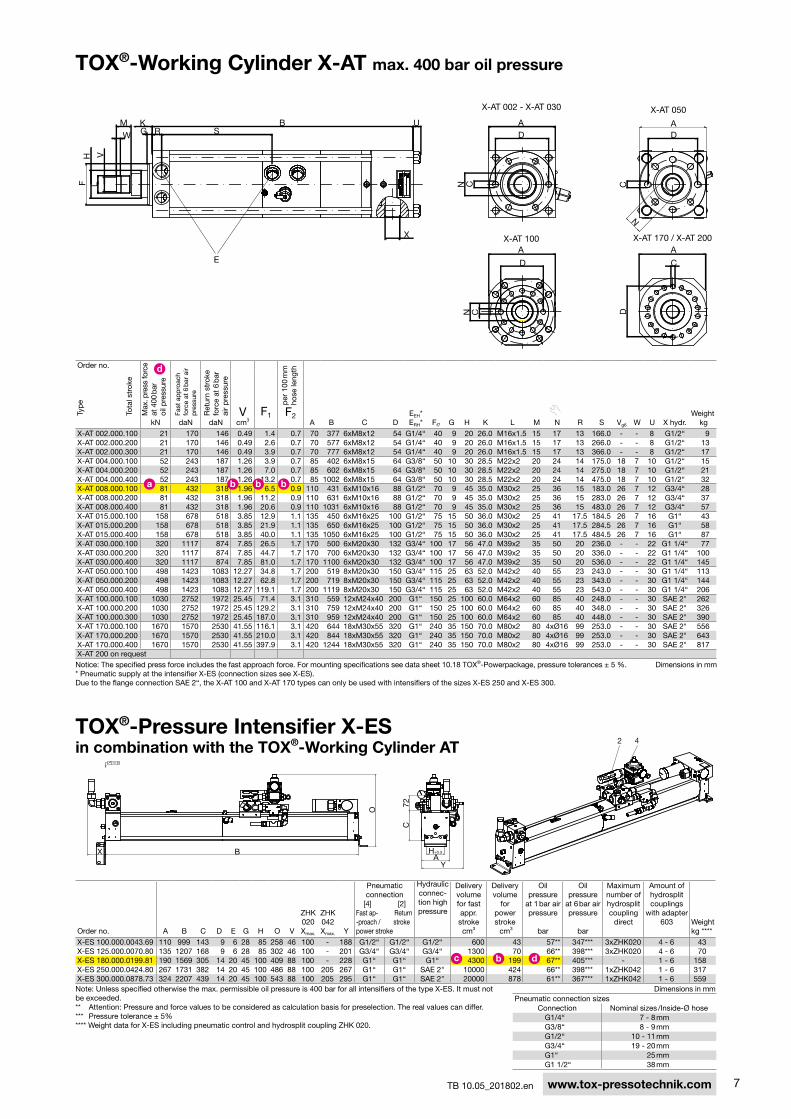
TOX®-Working Cylinder X-AT max. 400 bar oil pressure
Order no.
Max
. pre
ss fo
rce
at 4
00 b
ar
oil p
ress
ure
Fast
ap
pro
ach
forc
e at
6 b
ar a
ir p
ress
ure
ret
urn
stro
ke
forc
e at
6 b
ar
air
pre
ssur
e
Vcm3
F1 F2A B c D
eeh*erh* Ff7 G h k L M n r s Vg6 W U X hydr.
Weight kg
Typ
e
Tota
l str
oke
kn dan dan
X-AT 002.000.100 21 170 146 0.49 1.4 0.7 70 377 6xM8x12 54 G1/4“ 40 9 20 26.0 M16x1.5 15 17 13 166.0 - - 8 G1/2“ 9X-AT 002.000.200 21 170 146 0.49 2.6 0.7 70 577 6xM8x12 54 G1/4“ 40 9 20 26.0 M16x1.5 15 17 13 266.0 - - 8 G1/2“ 13X-AT 002.000.300 21 170 146 0.49 3.9 0.7 70 777 6xM8x12 54 G1/4“ 40 9 20 26.0 M16x1.5 15 17 13 366.0 - - 8 G1/2“ 17X-AT 004.000.100 52 243 187 1.26 3.9 0.7 85 402 6xM8x15 64 G3/8“ 50 10 30 28.5 M22x2 20 24 14 175.0 18 7 10 G1/2“ 15X-AT 004.000.200 52 243 187 1.26 7.0 0.7 85 602 6xM8x15 64 G3/8“ 50 10 30 28.5 M22x2 20 24 14 275.0 18 7 10 G1/2“ 21X-AT 004.000.400 52 243 187 1.26 13.2 0.7 85 1002 6xM8x15 64 G3/8“ 50 10 30 28.5 M22x2 20 24 14 475.0 18 7 10 G1/2“ 32X-AT 008.000.100 81 432 318 1.96 6.5 0.9 110 431 6xM10x16 88 G1/2“ 70 9 45 35.0 M30x2 25 36 15 183.0 26 7 12 G3/4“ 28X-AT 008.000.200 81 432 318 1.96 11.2 0.9 110 631 6xM10x16 88 G1/2“ 70 9 45 35.0 M30x2 25 36 15 283.0 26 7 12 G3/4“ 37X-AT 008.000.400 81 432 318 1.96 20.6 0.9 110 1031 6xM10x16 88 G1/2“ 70 9 45 35.0 M30x2 25 36 15 483.0 26 7 12 G3/4“ 57X-AT 015.000.100 158 678 518 3.85 12.9 1.1 135 450 6xM16x25 100 G1/2“ 75 15 50 36.0 M30x2 25 41 17.5 184.5 26 7 16 G1“ 43X-AT 015.000.200 158 678 518 3.85 21.9 1.1 135 650 6xM16x25 100 G1/2“ 75 15 50 36.0 M30x2 25 41 17.5 284.5 26 7 16 G1“ 58X-AT 015.000.400 158 678 518 3.85 40.0 1.1 135 1050 6xM16x25 100 G1/2“ 75 15 50 36.0 M30x2 25 41 17.5 484.5 26 7 16 G1“ 87X-AT 030.000.100 320 1117 874 7.85 26.5 1.7 170 500 6xM20x30 132 G3/4“ 100 17 56 47.0 M39x2 35 50 20 236.0 - - 22 G1 1/4“ 77X-AT 030.000.200 320 1117 874 7.85 44.7 1.7 170 700 6xM20x30 132 G3/4“ 100 17 56 47.0 M39x2 35 50 20 336.0 - - 22 G1 1/4“ 100X-AT 030.000.400 320 1117 874 7.85 81.0 1.7 170 1100 6xM20x30 132 G3/4“ 100 17 56 47.0 M39x2 35 50 20 536.0 - - 22 G1 1/4“ 145X-AT 050.000.100 498 1423 1083 12.27 34.8 1.7 200 519 8xM20x30 150 G3/4“ 115 25 63 52.0 M42x2 40 55 23 243.0 - - 30 G1 1/4“ 113X-AT 050.000.200 498 1423 1083 12.27 62.8 1.7 200 719 8xM20x30 150 G3/4“ 115 25 63 52.0 M42x2 40 55 23 343.0 - - 30 G1 1/4“ 144X-AT 050.000.400 498 1423 1083 12.27 119.1 1.7 200 1119 8xM20x30 150 G3/4“ 115 25 63 52.0 M42x2 40 55 23 543.0 - - 30 G1 1/4“ 206X-AT 100.000.100 1030 2752 1972 25.45 71.4 3.1 310 559 12xM24x40 200 G1“ 150 25 100 60.0 M64x2 60 85 40 248.0 - - 30 sAe 2" 262X-AT 100.000.200 1030 2752 1972 25.45 129.2 3.1 310 759 12xM24x40 200 G1“ 150 25 100 60.0 M64x2 60 85 40 348.0 - - 30 sAe 2" 326X-AT 100.000.300 1030 2752 1972 25.45 187.0 3.1 310 959 12xM24x40 200 G1“ 150 25 100 60.0 M64x2 60 85 40 448.0 - - 30 sAe 2" 390X-AT 170.000.100 1670 1570 2530 41.55 116.1 3.1 420 644 18xM30x55 320 G1“ 240 35 150 70.0 M80x2 80 4xØ16 99 253.0 - - 30 sAe 2" 556X-AT 170.000.200 1670 1570 2530 41.55 210.0 3.1 420 844 18xM30x55 320 G1“ 240 35 150 70.0 M80x2 80 4xØ16 99 253.0 - - 30 sAe 2" 643X-AT 170.000.400 1670 1570 2530 41.55 397.9 3.1 420 1244 18xM30x55 320 G1“ 240 35 150 70.0 M80x2 80 4xØ16 99 253.0 - - 30 sAe 2" 817X-AT 200 on request
d
b b ba
note: Unless specified otherwise the max. permissible oil pressure is 400 bar for all intensifiers of the type X-es. it must not be exceeded.** Attention: Pressure and force values to be considered as calculation basis for preselection. The real values can differ.*** Pressure tolerance ± 5%**** Weight data for X-es including pneumatic control and hydrosplit coupling Zhk 020.
TOX®-Pressure Intensifier X-ES in combination with the TOX®-Working Cylinder AT
Order no. A B c D e G h O V
Zhk 020 Xmax.
Zhk 042 Xmax. Y
Pneumatic connection
[4] [2] Fast ap- return -proach / stroke power stroke
hydraulic connec-tion high pressure
Delivery volume for fast appr. stroke cm3
Delivery volume
forpower stroke cm3
Oil pressure
at 1 bar air pressure
bar
Oil pressure
at 6 bar air pressure
bar
Maximum number of hydrosplit coupling
direct
Amount of hydrosplit couplings
with adapter 603 Weight
kg ****
X-es 100.000.0043.69 110 999 143 9 6 28 85 258 46 100 - 188 G1/2“ G1/2“ G1/2“ 600 43 57** 347*** 3xZhk020 4 - 6 43X-es 125.000.0070.80 135 1207 168 9 6 28 85 302 46 100 - 201 G3/4“ G3/4“ G3/4“ 1300 70 66** 398*** 3xZhk020 4 - 6 70X-es 180.000.0199.81 190 1569 305 14 20 45 100 409 88 100 - 228 G1“ G1“ G1“ 4300 199 67** 405*** - 1 - 6 158X-es 250.000.0424.80 267 1731 382 14 20 45 100 486 88 100 205 267 G1“ G1“ sAe 2" 10000 424 66** 398*** 1xZhk042 1 - 6 317X-es 300.000.0878.73 324 2207 439 14 20 45 100 543 88 100 205 295 G1“ G1“ sAe 2" 20000 878 61** 367*** 1xZhk042 1 - 6 559
dbc
notice: The specified press force includes the fast approach force. For mounting specifications see data sheet 10.18 TOX®-Powerpackage, pressure tolerances ± 5 %.* Pneumatic supply at the intensifier X-es (connection sizes see X-es).Due to the flange connection sAe 2“, the X-AT 100 and X-AT 170 types can only be used with intensifiers of the sizes X-es 250 and X-es 300.
Dimensions in mm
Dimensions in mmPneumatic connection sizes
connection nominal sizes /inside-Ø hoseG1/4“ 7 - 8 mmG3/8“ 8 - 9 mmG1/2“ 10 - 11 mmG3/4“ 19 - 20 mmG1“ 25 mmG1 1/2“ 38 mm
per
100
mm
ho
se le
ngth

8
2
16
7
4
3 3
7
5
13
5
7
4
TB 10.05_201802.enwww.tox-pressotechnik.com
TOX®-Hydrosplit Coupling type ZHKeasy separation of pressure intensifier and drive cylinder
in order to ship the components already filled with oil and for easy installation, the TOX®-hydrosplit coupling has been developed. This allows to connect all components without any introduction of air to the system and without leakage. The coupling is available as manual or electric switchable.
connection hose side connection intensifier side connection hose side connection intensifier side
TOX®-Hydrosplit Coupling type ZHK 020.000 manually switchable
hose hose
disconnected connected
can be used with drives up to hZL 74 / X-AT 050.For bigger cylinders request the Zhk 042 (with sAe 2“ connection.)
can be used with drives up to hZL 74 / X-AT 050.
disconnected
connected
Part 1 Part 2 1 coupling half – hose side2 coupling half – intensifier side3 Threaded bushing – do not open4 Bleed screw5 coupling assembly screws6 coupling mounting screws to
intensifier7 Valve stem to open or close valve
hose
hose
Part 1 Part 3
Features: •Valve is operated with a drive
cylinder. no pressure drop•cylinders can be activated
independently. return stroke posi-tion can be controlled
•One valve size can be used on all cylinders
•improved cycle time•Prepared for position feedback
Technical data:
Operating voltage 24 V / DcPower consumption 4.4 W
includes solenoid Din 43650 (isO 4400) design A, with LeD
TOX®-Hydrosplit Coupling type ZHK 020.001 with solenoid operated valve

9
603
90° / 180° / 270°
TB 10.05_201802.en www.tox-pressotechnik.com
TOX®-Hydrosplit Coupling type ZHKcombinable with up to 6 drive cylinders
Pressure Intensifier X-ES with up to 3 working cylinders
The pressure intensifiers X-es 100 and X-es 125 allow direct mounting of 1 to 3 hydrosplit couplings Zhk 020.
Pressure Intensifier X-ES with 4 and more working cylinders When mounting 4 to 6 working cylinders to the inten-sifiers X-es 100 and X-es 125 with the hydrosplit coupling, the adapter 603 is used.
The adapter type 603 is always used when mounting hydrosplit couplings Zhk 020 to the intensifiers X-es 180, X-es 250 and X-es 300.
Variant 1 Variant 2 Variant 3 Variant 4
HZLX- AT
HZLX- AT
X-ES
HydrosplitCoupling
X-ES
HZLX- AT
HydrosplitCoupling
X-ES
HZLX- AT
HydrosplitCoupling
X-ES
HZLX- AT
HydrosplitCoupling
Mounting variants of TOX®-hydrosplit coupling with 1 – 6 hoses. swivel fitting allows each hose to be independently oriented.
5
3
1
6
4
2
Standard mounting sequence of theTOX -Hydrosplit Coupling ZHK 020®
Mounting variants

10
A B
C
Hm
in.
Hm
in.
Rmin.
Rmin.
Hm
in.
Rmin.
Rmin
.
Hm
in.
TB 10.05_201802.enwww.tox-pressotechnik.com
Hydraulic hosesThe connection between the drive cylinders and pneumohydraulic intensifier
Examples of the correct installation of hydraulic hoses
wrong
right
wrong
right
hoses must be installed so that it can be bled properly!
wrong
right
wrong
right
Other connection variants on request.
Ordering example:
Zs 01 - 1000
hose length
variant no.
Connection variants
Variant no. cylinder hZL / X-AT side intensifier X-es side connection
Zs 01
2 x straight connection
Zs 02
1 x 90° elbow on X-es1 x straight connection
on hZL / X-AT
Zs 03
1 x straight connection on X-es
1 x 90° elbow on hZL / X-ATHose length
Allocation of the hydraulic hoses to the drive cylinders
Drive standard hose lengthsnominal
sizehoses Ø D
hose dimensions hose weight incl. oil* [kg / m]A B c hmin rmin
AT 001 500 / 1000 / 1500 / 2000 / 2500 / 3000 10 21 88 75 84 220 150 0.6X-AT 002 / X-AT 004 500 / 1000 / 1500 / 2000 / 2500 / 3000 12 24 94 85 92 275 200 0.8X-AT 008 500 / 1000 / 1500 / 2000 / 2500 / 3000 16 28.5 101 90 74 320 240 1.3X-AT 015 500 / 1000 / 1500 / 2000 / 2500 / 3000 19 32 118 125 137 375 280 1.8X-AT 030 /X-AT 050 500 / 1000 / 1500 / 2000 / 2500 / 3000 25 39 145 160 100 420 270 2.6X-AT 100 / X-AT 170 1000 / 1500 / 2000 / 2500 / 3000 50 71 200 200 176 1120 920 6.8hZL 02 500 / 1000 / 1500 / 2000 / 2500 / 3000 10 21 88 75 84 220 150 0.6hZL 05 500 / 1000 / 1500 / 2000 / 2500 / 3000 12 24 94 85 92 275 200 0.8hZL 07 / hZL 11 500 / 1000 / 1500 / 2000 / 2500 / 3000 16 28.5 101 90 74 320 240 1.3hZL 19 / hZL 29 500 / 1000 / 1500 / 2000 / 2500 / 3000 19 32 118 125 137 375 280 1.8hZL 48 / hZL 74 500 / 1000 / 1500 / 2000 / 2500 / 3000 25 39 145 160 100 420 270 2.6rmin: smallest allowable bending radius *without screw-type fittings Dimensions in mm

11TB 10.05_201802.en www.tox-pressotechnik.com
Pneumatic control diagram (example):TOX®-Powerpackage X-kT-system for up to 6 drive cylinders (X-AT or hZL) with pneumatic control, power stroke valve and hydrosplit coupling Zhk 020.
Additional informationPneumatic control diagram
Power strokevalve
2 6.1
1431
1
3
X
P
P Distributorledge ZVL
Control throttle X
2
2
4.1
HDM 4
X
X
HD
HZ/HZL
AT/X-ATZHK 020
21
ZHK 020
212 1
HD
HDM6
X-ES
4.28
3
1
Not included in the scope ofdelivery!Maintenance unit required!Con�guration range:min. 2 bar, max. 10 bar
3
15
4
Control system for X-KT systems for 1-2 X-AT/HZLwith power stroke valve, with fast approach stroke support and control throttle X
Description:Storage piston during fast approach pressurized with fast approach pressure.Storage piston during return stroke pressurized with reduced air spring pressure.Power stroke piston permanently pressurized with reduced air spring pressure.
2
2
NDB
22
2
4.1 44
4
4.4
6
1
2
Pressure regulatorpneumatic spring0.8 bar set permanently
12
12<->1

12 TB 10.05_201802.enwww.tox-pressotechnik.com
Additional informationOrdering information
The TOX®-Powerpackage X-kT-system will be delivered in detached condition but completely filled with oil.
All components are ready for connection including colour-guided pneumatic plug-in-system.
You will receive:•2 x hZL incl. hoses and hydrosplit coupling•1 x X-es incl. hydrosplit coupling (manually switchable)
The following ordering example (TOX®-Pressure intensifier with 2 TOX®-hydraulic cylinders hZL) shows, how to order a TOX®-Powerpackage X-kT system (either with working part X-AT or with hydraulic cylinder hZL):
Ordering data: Example: Quantity:Order no. of the intensifier X-es X-es 125.000.0123.48 1
Order no. of either the TOX®-Working cylinder X-AT or the TOX®-hydraulic cylinder hZL
hZL 07.101.100 2
Length and variant no. of the hydraulic hose Zs Zs 01.1000 2
Type of TOX®-hydrosplit coupling and mounting variant Zhk 020.000, Mounting variant 1
2
subject to technical changes.