Embed Size (px)
Citation preview
Full Terms & Conditions of access and use can be found athttp://www.tandfonline.com/action/journalInformation?journalCode=tctm20
Download by: [West Virginia University Libraries] Date: 31 May 2017, At: 11:04
Combustion Theory and Modelling
ISSN: 1364-7830 (Print) 1741-3559 (Online) Journal homepage: http://www.tandfonline.com/loi/tctm20
Towards a predictive scenario of a burningaccident in a mining passage
Sinan Demir, Vitaly Bychkov (DECEASED), Sri Hari Ramakrishna Chalagalla &V'yacheslav Akkerman
To cite this article: Sinan Demir, Vitaly Bychkov (DECEASED), Sri Hari Ramakrishna Chalagalla& V'yacheslav Akkerman (2017): Towards a predictive scenario of a burning accident in a miningpassage, Combustion Theory and Modelling
To link to this article: http://dx.doi.org/10.1080/13647830.2017.1328129
Published online: 31 May 2017.
Submit your article to this journal
View related articles
View Crossmark data

Combustion Theory and Modelling, 2017
https://doi.org/10.1080/13647830.2017.1328129
Towards a predictive scenario of a burning accident in a miningpassage
Sinan Demira, Vitaly Bychkov (DECEASED)b, Sri Hari Ramakrishna Chalagallaa andV’yacheslav Akkermana∗
aCenter for Innovation in Gas Research and Utilization (CIGRU), Center for Alternative Fuels,Engines and Emissions (CAFEE), Department of Mechanical and Aerospace Engineering, West
Virginia University, Morgantown, West Virginia 26506-6106, USA; bDepartment of Physics, UmeaUniversity, Umea 90187, Sweden
(Received 31 October 2016; accepted 27 April 2017)
To reveal the inner mechanisms of a combustion accident in a coalmine, the key stagesand characteristics of premixed flame front evolution such as the flame shapes, propa-gation speeds, acceleration rates, run-up distances and flame-generated velocity profilesare scrutinised. The theories of globally spherical, expanding flames and of finger-flameacceleration are combined into a general analytical formulation. Two-dimensional andcylindrical mining passages are studied, with noticeably stronger acceleration found inthe cylindrical geometry. The entire acceleration scenario may promote the total burningrate by up to two orders of magnitude, to a near-sonic value. Starting with gaseous com-bustion, the analysis is subsequently extended to gaseous-dusty environments. Specif-ically, combustible dust (e.g. coal), inert dust (e.g. sand), and their combination areconsidered, and the influence of the size and concentration of the dust particles is quan-tified. In particular, small particles influence flame propagation more than large ones,and flame acceleration increases with the concentration of a combustible dust, until theconcentration attains a certain limit.
Keywords: dust combustion; mining safety; fire safety; Darrieus–Landau instability;finger flame shape
Nomenclature
atip flame tip acceleration [m s–2]B frequency factor characterising the rate of gas phase oxidation of a gaseous fuel
[s−1]cs concentration of coal particles [kg m–3]co local sound speed [m s–1]C constant defined in Equation (2) [m s–n]
Cp specific heat of gaseous air-fuel mixture [kJ kg–1 K–1]Cs specific heat of dust particles [kJ kg–1 K–1]CT entire specific heat [kJ kg–1 K–1]Dth thermal diffusivity [m2 s–1]Ea activation energy characterising the gas phase reaction [kJ mol–1]H distance to the ignition point from a tunnel side walls [m]
∗Corresponding author. Email: [email protected]
C© 2017 Informa UK Limited, trading as Taylor & Francis Group

2 S. Demir et al.
�hCH4 specific enthalpy of formation for methane [kJ kg–1]k perturbation wave-number [m−1]
kDL Darrius–Landau (DL) cut-off wave number [m−1]ku thermal conductivity [W K–1 m–1]Le Lewis numberLf flame thickness [m]Lv heat necessary for gasification per unit volume [kJ m–3]
mfuel total amount of fuel available per unit volume (accounting for the volatilities)[kg m–3]
mCH4 mass of methane available for combustion per unit volume [kg m–3]mair mass of air available for combustion per unit volume [kg m–3]
MCH4 molar mass of methane [kg mol–1]Mair molar mass of air [kg mol–1]
ns number of particles per unit volume [m−3]nair number of moles of air per unit volume [mol]
n exponent given in Equation (1)N exponent given in Equation (40)P pressure [Pa]
Pr Prandtl numberR characteristic length scale [m]Rf radius of the flame skirt [m]Ru universal gas constant [kJ mol–1 K–1]
r radial (cylindrical) coordinate [m]rs radius of a single particle [μm]SL unstretched laminar flame propagation velocity in gaseous environment [m s–1]
SL,d unstretched laminar flame propagation velocity in gaseous-dusty environment[m s–1]
T temperature [K]Tb adiabatic flame temperature [K]Tf flame temperature with particles [K]Ts surface temperature of a dust particle [K]Tu temperature of the reactants [K]Tv devolatilisation temperature [K]
t time [s]tr residence time [s]
tsph characteristic time when the spherical flame transforms into a finger-shaped front[s]
twall time when the flame skirt contacts a wall [s]u velocity [m s–1]
UDL instantaneous global flame speed with respect to the fuel mixture [m s–1]Utip flame tip velocity [m s–1]
Vs volume of a single particle [m3]x radial (2D) coordinate [m]
Ze Zeldovich numberZrud run-up-distance [m]Ztip flame tip position [m]
z axial coordinate [m]Q heat released during combustion per unit volume [kJ m–3]

Combustion Theory and Modelling 3
w′v devolatalisation rate [kg m–3 s–1]
wv total mass of volatilities released per unit volume [kg m–3]
Greek symbols
� thermal expansion coefficientφ gaseous mixture equivalence ratioφs modified equivalence ratio due to the addition of coal particles
σDL growth rate of the Darrieus–Landau (DL) instability [s−1]ρ density of a coal-dust/gas mixture [kg m–3]ρs density of a dust single particle [kg m–3]ρu density of a gas mixture [kg m–3]� coefficient defined in Equation (3)
λDL DL cut-off wavelength [m]
Subscripts
s coal dust particleu ambient conditions1 air-fuel mixture2 burnt matter
1. Introduction
Historically, the mining industry has one of the highest injury and fatality rates for employ-ees. While mining accidents are caused by a multitude of reasons, spontaneous methanedeflagrations and detonations in the presence of coal dust constitute the most commonhazard. Among the recent examples of such dust/gas disasters, the 2014 mining catastrophein Soma, Turkey resulted in over 300 deaths. To reduce the risk of these accidental burningevents, researchers worldwide analyse – experimentally, theoretically and computation-ally – numerous factors affecting the mechanisms of flame propagation and accelerationin methane–air and methane–air–coal-dust mixtures. In particular, Chatrathi et al. [1] in-vestigated methane–air flame propagation in industrial-scale piping. Silvestrini et al. [2]provided simplified formulas to evaluate the flame velocities as well as the run-up distancesof the deflagration-to-detonation transition (DDT) for flammable mixtures in smooth andobstructed tubes. Chen et al. [3] studied the structure and dynamics of flames at variousequivalence ratios; they suggested that flame acceleration occurs only after a transition toturbulence, which actually determines the structure of the flame front. In another study, Biet al. [4] investigated premixed methane–air flames in relatively long pipes by means ofnumerical simulations. Kjaldman [5] performed a pioneering numerical study on burningin a gaseous environment with combustible dust impurities, employing a computationalfluid dynamics (CFD) tool with small-scale dust flames. Furthermore, Liu et al. [6] con-ducted experiments on coal-dust–air mixture explosions under a weak ignition conditionin a horizontal tube of diameter ∼0.2 m. Skjold et al. [7] investigated, experimentallyand numerically, constant-volume dusty/gaseous detonations. Houim et al. [8] simulatedthe interaction of shock waves and the resulting shear layers with coal-dust layers. Gard-ner et al. [9] undertook large-scale experiments to investigate detonations spreading inflowing coal-dust–air suspensions in a duct of diameter 0.6 m. Bartknecht [10,11] per-formed experiments on coal-dust–air detonations in two tubes of different diameters andlengths; the maximum flame speeds attained in a tube of length 130 m and diameter 2.5 mwere 500 m s–1 and 700 m s–1, for dust concentrations of 250 g m–3 and 500 g m–3,respectively.
4 S. Demir et al.
Nevertheless, up to now there was not a unified analysis capturing all the fundamentalsand providing enough details about a flame acceleration mechanism, starting from theinitial stages of the process to the onset of the detonation. The present work is a stepin this direction. Earlier experiments by Oppenheim [12] and Urtiew [13] were devotedto hydrogen-oxygen flame acceleration, at the initial stage of burning, and transition todetonation. It was concluded that an initially laminar accelerating flame creates compressionand then shock waves ahead of it, which subsequently leads to flame turbulisation and thedetonation onset. Clanet and Searby [14] have identified a finger-shaped mechanism offlame acceleration at the early stages of burning in tubes, which has been subsequentlyjustified numerically and developed into a quantitative theory [15]. Specifically, a flamepropagating in a cylindrical tube with ideally slip adiabatic walls was considered, with oneend of the tube closed, and a flame ignited at the symmetry axis at the closed end, andpropagating to the open one. In that case, the flame front develops from a hemisphericalshape at the beginning to a finger-shape, accompanied by the concomitant exponentialgrowth of the surface area of the flame front and, thereby, associated increase in the flamevelocity. This acceleration is fast, but it lasts only for a short time interval – until a flameskirt contacts a wall. This acceleration mechanism is Reynolds-independent, and is thereforeequally strong in micro-tubes and mining passages. However, in practice, Re-dependentfactors such as combustion instabilities and/or turbulence provide corrections to the flameacceleration scenario, making it Reynolds-dependent as well [16].
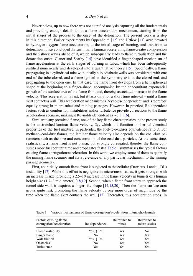
Similar to any premixed flame, one of the key flame characteristics in the present studyis the unstretched laminar flame velocity, SL, which is a function of thermal-chemicalproperties of the fuel mixture; in particular, the fuel-to-oxidiser equivalence ratio φ. Formethane–coal-dust flames, the laminar flame velocity also depends on the coal-dust pa-rameters such as the size and concentration of the coal-dust particles. At the same time,realistically, a flame front is not planar, but strongly corrugated; thereby, the flame con-sumes more fuel per unit time and propagates faster. Table 1 summarises the typical factorscausing flame corrugation/acceleration. In this work, we employ some of them to quantifythe mining flame scenario and fix a relevance of any particular mechanism to the miningpassage geometry.
First, an initially smooth flame front is subjected to the cellular (Darrieus–Landau, DL)instability [17]. While this effect is negligible in micro/meso-scales, it gets stronger withan increase in size, providing a 2.5–10 increase in the flame velocity in tunnels of a humanheight size (1.7–2 m diameter) [18,19]. Second, when a flame front starts to approach thetunnel side wall, it acquires a finger-like shape [14,15,20]. Then the flame surface areagrows quite fast, promoting the flame velocity by one more order of magnitude by thetime when the flame skirt contacts the wall [15]. Thereafter, this acceleration stops. In
Table 1. Various mechanisms of flame corrugation/acceleration in tunnels/channels.
Factors causing flamecorrugation/acceleration Re-dependence
Relevance tomines
Relevance tomicro-scales
Flame instability Yes, ↑ Re Yes NoFinger flame No Yes YesWall friction Yes, ↓ Re Yes YesObstacles No Yes YesTurbulence Yes Yes Yes
Combustion Theory and Modelling 5
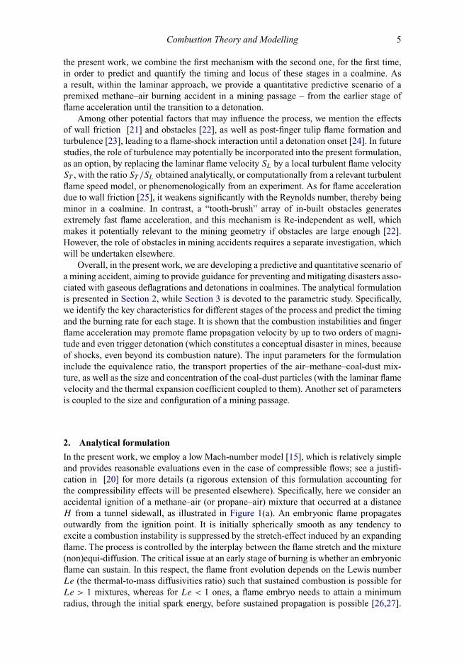
the present work, we combine the first mechanism with the second one, for the first time,in order to predict and quantify the timing and locus of these stages in a coalmine. Asa result, within the laminar approach, we provide a quantitative predictive scenario of apremixed methane–air burning accident in a mining passage – from the earlier stage offlame acceleration until the transition to a detonation.
Among other potential factors that may influence the process, we mention the effectsof wall friction [21] and obstacles [22], as well as post-finger tulip flame formation andturbulence [23], leading to a flame-shock interaction until a detonation onset [24]. In futurestudies, the role of turbulence may potentially be incorporated into the present formulation,as an option, by replacing the laminar flame velocity SL by a local turbulent flame velocityST , with the ratio ST /SL obtained analytically, or computationally from a relevant turbulentflame speed model, or phenomenologically from an experiment. As for flame accelerationdue to wall friction [25], it weakens significantly with the Reynolds number, thereby beingminor in a coalmine. In contrast, a “tooth-brush” array of in-built obstacles generatesextremely fast flame acceleration, and this mechanism is Re-independent as well, whichmakes it potentially relevant to the mining geometry if obstacles are large enough [22].However, the role of obstacles in mining accidents requires a separate investigation, whichwill be undertaken elsewhere.
Overall, in the present work, we are developing a predictive and quantitative scenario ofa mining accident, aiming to provide guidance for preventing and mitigating disasters asso-ciated with gaseous deflagrations and detonations in coalmines. The analytical formulationis presented in Section 2, while Section 3 is devoted to the parametric study. Specifically,we identify the key characteristics for different stages of the process and predict the timingand the burning rate for each stage. It is shown that the combustion instabilities and fingerflame acceleration may promote flame propagation velocity by up to two orders of magni-tude and even trigger detonation (which constitutes a conceptual disaster in mines, becauseof shocks, even beyond its combustion nature). The input parameters for the formulationinclude the equivalence ratio, the transport properties of the air–methane–coal-dust mix-ture, as well as the size and concentration of the coal-dust particles (with the laminar flamevelocity and the thermal expansion coefficient coupled to them). Another set of parametersis coupled to the size and configuration of a mining passage.
2. Analytical formulation
In the present work, we employ a low Mach-number model [15], which is relatively simpleand provides reasonable evaluations even in the case of compressible flows; see a justifi-cation in [20] for more details (a rigorous extension of this formulation accounting forthe compressibility effects will be presented elsewhere). Specifically, here we consider anaccidental ignition of a methane–air (or propane–air) mixture that occurred at a distanceH from a tunnel sidewall, as illustrated in Figure 1(a). An embryonic flame propagatesoutwardly from the ignition point. It is initially spherically smooth as any tendency toexcite a combustion instability is suppressed by the stretch-effect induced by an expandingflame. The process is controlled by the interplay between the flame stretch and the mixture(non)equi-diffusion. The critical issue at an early stage of burning is whether an embryonicflame can sustain. In this respect, the flame front evolution depends on the Lewis numberLe (the thermal-to-mass diffusivities ratio) such that sustained combustion is possible forLe > 1 mixtures, whereas for Le < 1 ones, a flame embryo needs to attain a minimumradius, through the initial spark energy, before sustained propagation is possible [26,27].

6 S. Demir et al.
Consequently, keeping Le < 1 in a mining environment may improve the flame safetystandards. It is also noted that Le ∼ 1 for the majority of methane–air flames.
Stage 1: Quasi-spherical, self-similar accelerative flame expansion
Let us consider the case when a flame has survived and keeps propagating. In the presentstudy, we are interested mostly in large scales such that the flame stretch will eventuallybe neglected. At the early stage of burning, the flame front expands with a constant speed,dRf /dt = �SL, with respect to the ignition point, where Rf (t) is the instantaneous flameradius, SL the unstretched laminar flame propagation speed, as discussed above, and � =ρu/ρb is the thermal expansion factor, which is coupled to the equivalence ratio φ. As aflame “ball” grows in size and the stretch intensity reduces, the diffusional-thermal cellswould develop over the surface of Le < 1 flames [28]. Subsequently, the flame thicknessrelative to the global flame radius is reduced, leading to the onset of hydrodynamic (DL)flame instability mode. The latter generates hydrodynamic cells over the flame surface,regardless of Le, and will eventually dominate in the surface morphology [28,29]. Thecontinuous generation of new cells leads to the continuous increase in the flame surfacedensity and thereby an expanding flame self-accelerates in a scale-invariant (self-similar)manner; see Figure 1(b). According to numerous experimental and computational studies,a reasonable fitting law for such acceleration is [30]:
Rf = R0 + Ctn ≈ Ctn, (1)
where R0 plays the role of a critical radius related to the transition to the cellular flamestructure (it can be neglected within the frame of a large-scale formulation), n ≈ 1.3 − 1.4in the most of studies; and the factor C can be evaluated as [30,31]:
C = kn−1DL (�SL/n)n, (2)
where kDL is the DL cut-off wavenumber that appears in the Pelce–Clavin dispersionrelation [32]:
σDL (k) = � (�) SLk (1 − k/kDL) , � (�) = �
� + 1
[(� + 1 − 1
�
)1/2
− 1
], (3)
Figure 1. Illustration of quasi-spherical flame expansion: the stages of ignition, uniform propagationof a smooth front (a) as well as self-similar acceleration of a cellular front (b).
Combustion Theory and Modelling 7
and it is coupled to the DL critical wavelength as kDL = 2π/λDL; the latter, in turn,depends on � and is proportional to the flame thickness, which is conventionally definedas Lf = Dth/SL, where Dth is the thermal diffusivity, with λDL ≈ (30 − 100)Lf for � =5 − 8. In the present work, we employ the following formulas for λDL and, respectively,kDL [23]:
λDL = 2πLf
(1 + (� + 1)
(� − 1)2� ln �
), kDL = L−1
f
(1 + (� + 1)
(� − 1)2� ln �
)−1
. (4)
With power-law flame acceleration, Equation (1), the global (radial) flame velocity withrespect to the ignition point is not a constant �SL any more, but a time-dependentquantity:
dRf /dt = nCtn−1 = (kDL/n)n−1 (�SL)ntn−1. (5)
To evaluate the instantaneous global flame velocity with respect to the fuel mixture, wedivide the result (5) by �, namely:
UDL = 1
�
dRf
dt= nC
�tn−1 = Sn
L
(�
nkDL
)n−1
tn−1. (6)
Stage 2: Finger-like flame acceleration
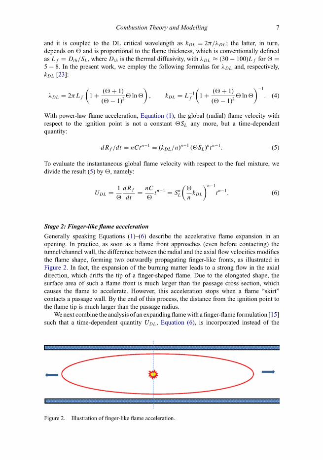
Generally speaking Equations (1)–(6) describe the accelerative flame expansion in anopening. In practice, as soon as a flame front approaches (even before contacting) thetunnel/channel wall, the difference between the radial and the axial flow velocities modifiesthe flame shape, forming two outwardly propagating finger-like fronts, as illustrated inFigure 2. In fact, the expansion of the burning matter leads to a strong flow in the axialdirection, which drifts the tip of a finger-shaped flame. Due to the elongated shape, thesurface area of such a flame front is much larger than the passage cross section, whichcauses the flame to accelerate. However, this acceleration stops when a flame “skirt”contacts a passage wall. By the end of this process, the distance from the ignition point tothe flame tip is much larger than the passage radius.
We next combine the analysis of an expanding flame with a finger-flame formulation [15]such that a time-dependent quantity UDL, Equation (6), is incorporated instead of the
Figure 2. Illustration of finger-like flame acceleration.
8 S. Demir et al.
(a)
endwall
Rf
Rside wall
z
flameskirt
fuelmixture
burntgas
(b
x
endwall
b)
burntgas
flametip
fum
Ztip
elixture
z
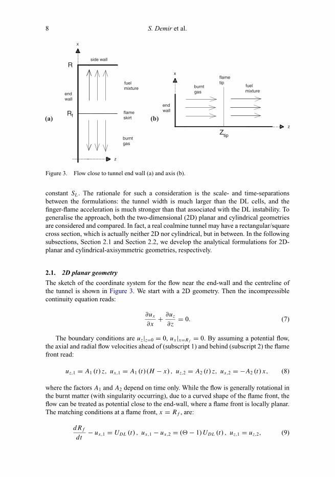
Figure 3. Flow close to tunnel end wall (a) and axis (b).
constant SL. The rationale for such a consideration is the scale- and time-separationsbetween the formulations: the tunnel width is much larger than the DL cells, and thefinger-flame acceleration is much stronger than that associated with the DL instability. Togeneralise the approach, both the two-dimensional (2D) planar and cylindrical geometriesare considered and compared. In fact, a real coalmine tunnel may have a rectangular/squarecross section, which is actually neither 2D nor cylindrical, but in between. In the followingsubsections, Section 2.1 and Section 2.2, we develop the analytical formulations for 2D-planar and cylindrical-axisymmetric geometries, respectively.
2.1. 2D planar geometry
The sketch of the coordinate system for the flow near the end-wall and the centreline ofthe tunnel is shown in Figure 3. We start with a 2D geometry. Then the incompressiblecontinuity equation reads:
∂ux
∂x+ ∂uz
∂z= 0. (7)
The boundary conditions are uz|z=0 = 0, ux |x=Rf= 0. By assuming a potential flow,
the axial and radial flow velocities ahead of (subscript 1) and behind (subscript 2) the flamefront read:
uz,1 = A1 (t) z, ux,1 = A1 (t) (H − x) , uz,2 = A2 (t) z, ux,2 = −A2 (t) x, (8)
where the factors A1 and A2 depend on time only. While the flow is generally rotational inthe burnt matter (with singularity occurring), due to a curved shape of the flame front, theflow can be treated as potential close to the end-wall, where a flame front is locally planar.The matching conditions at a flame front, x = Rf , are:
dRf
dt− ux,1 = UDL (t) , ux,1 − ux,2 = (� − 1) UDL (t) , uz,1 = uz,2, (9)
Combustion Theory and Modelling 9
where the first equation specifies the flame propagation velocity with respect to the fuelmixture, the second describes the jump of the normal velocity, and the third describes thecontinuity of the tangential velocity. Substituting Equation (8) into Equation (9), we obtainA1(t) = A2(t) = (� − 1)UDL(t)/H , and then the evolution equation for the flame skirtreads:
dRf
dt=
{(� − 1)
(1 − Rf
H
)+ 1
}UDL =
{(� − 1)
(1 − Rf
H
)+ 1
}Sn
L
(�
nkDL
)n−1
tn−1,
(10)with the initial condition Rf |t=0 = 0, and the solution:
t(Rf
) ={
�H
(� − 1) Cln
(�H
�H − (� − 1) Rf
)}1/n
= n
�SL
{�H
(� − 1) kn−1DL
ln
(�H
�H − (� − 1) Rf
)}1/n
, (11)
Rf (t)
H= �
� − 1
{1 − exp
[−� − 1
�HCtn
]}
= �
� − 1
{1 − exp
[−� − 1
�H
(kn−1DL
(�SL
n
)n)tn
]}. (12)
The characteristic time instant devoted to the transition from a globally-spherical toa finger-like flame shape, tsph, and the associated flame skirt location, Rf (tsph), can beevaluated as:
tsph ≈(
�H
(� − 1) C
)1/n
= n
�SL
(�H
(� − 1) kn−1DL
)1/n
,
Rf
(tsph
) =(1 − e−1
)�H
(� − 1)≈ 0.632
�H
(� − 1), (13)
with the burning rate at this instant being:
UDL
(tsph
) = nC
�tn−1sph = n
(C
�
)1/n (H
� − 1
)n − 1
n. (14)
We next focus on the flame tip, which evolution equation reads:
dZtip
dt= (� − 1) UDL (t)
Ztip
H+ �UDL (t) , (15)
with the initial condition Ztip|t=0 = 0, and the solution:
Ztip = �H
(� − 1)
{exp
[(� − 1)
�
Ctn
H
]− 1
}
= �H
(� − 1)
{exp
[(� − 1)
�
kn−1DL
H
(�SL
n
)n
tn
]− 1
}. (16)

10 S. Demir et al.
The flame skirt (in fact, its first “wing”) contacts the tunnel side wall whenRf = H , i.e.:
twall,1 ={
�H
(� − 1) Cln (�)
}1/n
= n
�SL
{�H
(� − 1) kn−1DL
ln (�)
}1/n
. (17)
The second flame wing contacts the opposite wall a little later, when Rf = 2R − H :
twall,2 ={
� (2R − H )
(� − 1) Cln (�)
}1/n
= n
�SL
{� (2R − H )
(� − 1) kn−1DL
ln (�)
}1/n
. (18)
Obviously, twall,1 = twall,2 if H = R and twall/tsph = n√
ln �. The velocity of the flametip in the laboratory reference frame and its acceleration are respectively given by:
dZtip
dt= Utip = nCtn−1 exp
((� − 1) Ctn
�H
), (19)
d2Ztip
dt2= atip = nCtn−1 exp
((� − 1) Ctn
�H
) {(n − 1) t−1 + ntn−1 � − 1
�
C
H
}. (20)
On can also readily check that in the case of n = 1, the DL instability disappears andall these formulas reproduce their counterparts of [20].
2.2. Cylindrical axisymmetric geometry
We next develop a similar analytical formulation for the cylindrical-axisymmetric geometry.In this case, the continuity equation for the incompressible flow reads [15]
1
r
∂ (rur )
∂r+ ∂uz
∂z= 0, (21)
with the boundary conditions uz|z=0 = 0, ur |r=rf= 0. Similar to the 2D case, assuming
potential flow in the fuel mixture, we find
uz,1 = A1 (t) z, ur,1 = A1 (t)
2
(H 2
r− r
), uz,2 = A2 (t) z, ur,2 = −A2 (t)
2r. (22)
The matching conditions are given by Equation (9). Then A1(t) = A2(t) =2(� − 1)UDL(t)Rf /H 2. Altogether, Equations (6) and (21)–(22) provide the evolutionequation for the flame skirt:
dRf
dt=
{� − (� − 1)
R2f
H 2
}UDL =
{� − (� − 1)
R2f
H 2
}Sn
L
(�
nkDL
)n−1
tn−1, (23)
with the solution:

Combustion Theory and Modelling 11
t(Rf
) ={
�H
2αCln
(� + α(Rf /H )
� − α(Rf /H )
)}1/n
= n
�SL
{�H
2αkn−1DL
ln
(� + α(Rf /H )
� − α(Rf /H )
)}1/n
,
(24)
Rf (t)
H= �
αtanh
(α
�
Ctn
H
)= �
αtanh
(α
�Hkn−1DL
(�SL
n
)n
tn)
, (25)
where α = √�(� − 1). The characteristic time instant devoted to the transition from a
globally spherical to a finger-like flame shape, tsph, and the flame skirt location at thisinstant, Rf (tsph), can be evaluated as:
tsph ≈(
�H
2αC
)1/n
= n
�SL
(�H
2αkn−1DL
)1/n
, Rf
(tsph
) = �H
αtanh (0.5) ≈ 0.46
√�
� − 1H,
(26)with the associated corrugated flame velocity being:
UDL
(tsph
) = nC
�tn−1sph = n
(C
�
)1/n(H
2α
)(n−1)/n
. (27)
We next focus on the flame tip, which evolution equation in this geometry reads:
dZtip
dt= 2 (� − 1) UDL (t)
Rf (t) Ztip
H 2+ �UDL (t) , (28)
with the solution:
Ztip = �H
2αsinh
(2
α
�
Ctn
H
)= H
2
√�
� − 1sinh
(2
√� − 1
�
kn−1DL
H
(�SL
n
)n
tn
). (29)
The first wing of the flame skirt contacts the tunnel side wall when Rf = H , i.e.:
twall,1 ={
�H
2αCln
(� + α
� − α
)}1/n
= n
�SL
{�H
2αkn−1DL
ln
(� + α
� − α
)}1/n
. (30)
The second flame wing contacts the opposite wall at:
twall,2 ={
�(2R − H )
2αCln
(� + α
� − α
)}1/n
= n
�SL
{�(2R − H )
2αkn−1DL
ln
(� + α
� − α
)}1/n
,
(31)
when Rf = 2R − H . Obviously, twall,1 = twall,2 if H = R and twall/tsph =n√
ln[(� + α)/(� − α)]. The flame tip velocity and acceleration in the laboratory referenceframe read:

12 S. Demir et al.
dZtip
dt= Utip = nCtn−1 cosh
(2αCtn
�H
), (32)
d2ztip
dt2= atip = nCtn−2
{2αnCtn
�Hsinh
(2αnCtn
�H
)+ (n − 1) cosh
(2αnCtn
�H
)}. (33)
Again, in the case of n = 1, the DL instability disappears and all these formulasreproduce their counterparts of [20].
3. Results and discussion
In this section, the analytical results of Section 2 are thoroughly investigated for a setof input parameters. Specifically, we start with the gaseous methane–air or propane–airflames, of various equivalence ratios, and then extend the analysis to methane–air–coal-dust combustion.
3.1. Homogeneously gaseous flames
While it is a methane–air accidental explosion that is most relevant to coalmines, forcomparison, and to identify the role of the type of a combustible, here we also investigatedpotential propane–air flame spreading. The thermal expansion factor � and the laminarflame velocity SL are tabulated versus the equivalence ratio φ: in Table 2, for the methane–air mixture, and in Table 3, for the propane–air one, respectively [33]. Based on thesetables, the characteristic timings of the process, tsph, Equations (13) and (26), and twall ,Equations (17), (18) and (30), (31) are presented in Figures 4 and 5 for the 2D planarand cylindrical axisymmetric geometries, respectively, with n = 1.4 and R = H = 1.05in both figures. It is recalled that these quantities, tsph and twall , play the key roles forflame acceleration and, thereby, the entire flame evolution scenario. Indeed, just after anignition, a flame tip moves in the same manner as the flame skirt, Equations (10)–(12)and (23)–(25), exhibiting a globally spherical (cellular) shape of an expanding flame frontwhile t < tsph. Then the flame skirt slows down, while the flame tip accelerates, therebyleading to very strong elongation and global acceleration of the flame front within theinterval tsph < t < twall . This acceleration is nevertheless limited in time: it terminatesas soon as the flame skirt contacts a wall, t = twall . The flame tip position, velocity andacceleration are presented in Figures 6–8 for the planar and cylindrical geometries. Here,Figures 6(a), 7(a) and 8(a) show the time evolution of these quantities, in a stoichiometric
Table 2. Methane–air flame parameters [33].
φ 0.6 0.7 0.8 0.9 1 1.1 1.2 1.3 1.4� 5.54 6.11 6.65 7.12 7.48 7.55 7.43 7.28 7.09SL (m s–1) 0.089 0.169 0.254 0.325 0.371 0.383 0.345 0.250 0.137
Table 3. Propane–air flame parameters [33].
φ 0.63 0.7 0.8 0.9 1 1.1 1.2 1.3 1.4� 6.04 6.56 7.15 7.66 8.02 8.08 8 7.88 7.74SL (m s–1) 0.147 0.217 0.303 0.374 0.418 0.429 0.399 0.322 0.226

Combustion Theory and Modelling 13
0
0.1
0.2
0.3
0.4
0.5
0.6
0.7
0.8
0.4 0.6 0.8 1 1.2 1.4 1.6
t sp
h,
tw
all [
sec]
Methane
Methane
Propane
Propane
( )spht
( )spht( )wallt
( )wallt
Figure 4. 2D planar geometry: The time limitations of the finger flame acceleration, tsph
(Equation (13)) and twall (Equation (17)), versus the equivalence ratio φ for propane–air and methane–air flames, R = H = 1 .05 m, n = 1.4.
0
0.1
0.2
0.3
0.4
0.5
0.6
0.7
0.8
0.4 0.6 0.8 1 1.2 1.4 1.6
t sph
, t w
all [
sec]
MethaneMethanePropanePropane
( )spht
( )spht( )wallt
( )wallt
Figure 5. Cylindrical axisymmetric geometry: The time limitations of the finger flame acceleration,tsph (Equation (26)), and twall (Equation (30)), versus the equivalence ratio φ for propane–air andmethane–air flames, R = H = 1 .05 m, n = 1.4.
Figure 6. (a) Evolution of flame tip position Zt ip in a stoichiometric (φ = 1) mixture and (b)Zt ip (twall) versus φ for methane–air and propane–air combustion in the 2D planar and cylindricalaxisymmetric geometries.
14 S. Demir et al.
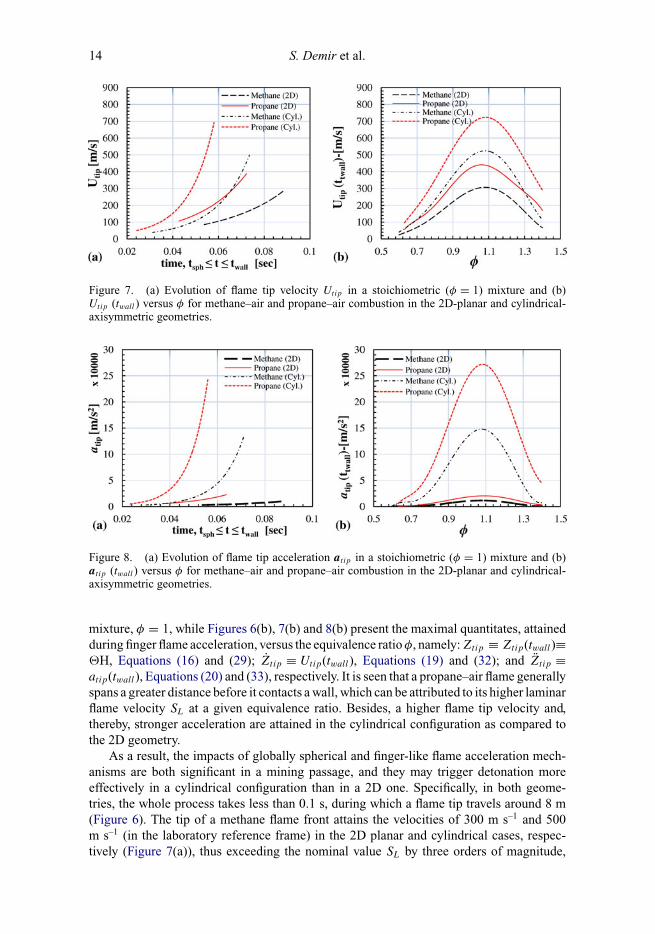
Figure 7. (a) Evolution of flame tip velocity Utip in a stoichiometric (φ = 1) mixture and (b)Utip (twall) versus φ for methane–air and propane–air combustion in the 2D-planar and cylindrical-axisymmetric geometries.
Figure 8. (a) Evolution of flame tip acceleration at ip in a stoichiometric (φ = 1) mixture and (b)at ip (twall) versus φ for methane–air and propane–air combustion in the 2D-planar and cylindrical-axisymmetric geometries.
mixture, φ = 1, while Figures 6(b), 7(b) and 8(b) present the maximal quantitates, attainedduring finger flame acceleration, versus the equivalence ratio φ, namely: Ztip ≡ Ztip(twall)≡�H, Equations (16) and (29); Ztip ≡ Utip(twall), Equations (19) and (32); and Ztip ≡atip(twall), Equations (20) and (33), respectively. It is seen that a propane–air flame generallyspans a greater distance before it contacts a wall, which can be attributed to its higher laminarflame velocity SL at a given equivalence ratio. Besides, a higher flame tip velocity and,thereby, stronger acceleration are attained in the cylindrical configuration as compared tothe 2D geometry.
As a result, the impacts of globally spherical and finger-like flame acceleration mech-anisms are both significant in a mining passage, and they may trigger detonation moreeffectively in a cylindrical configuration than in a 2D one. Specifically, in both geome-tries, the whole process takes less than 0.1 s, during which a flame tip travels around 8 m(Figure 6). The tip of a methane flame front attains the velocities of 300 m s–1 and 500m s–1 (in the laboratory reference frame) in the 2D planar and cylindrical cases, respec-tively (Figure 7(a)), thus exceeding the nominal value SL by three orders of magnitude,

Combustion Theory and Modelling 15
and the laminar flame velocity in the laboratory reference frame, �SL, by two orders. Forpropane–air combustion, the burning rate increases even higher, up to 400 m s–1 and 700m s–1 in the 2D planar and cylindrical axisymmetric geometries, respectively. In fact, itis Figure 7 that identifies whether a propagating flame front can attain a sonic/supersonicspeed in a coalmine, where a detonation occurs mostly due to an accidental ignition ofmethane, being thereby one of the major causes for a disaster. For methane–air burning,while such an overcome of the sound barrier is not observed in a 2D channel, in a cylin-drical geometry, it occurs for the equivalence ratios in the range 0.9 ≤ φ ≤ 1.2. For fasterpropane–air burning, this range is even wider in the cylindrical geometry, 0.8 ≤ φ ≤ 1.3,and it is also observed in a 2D planar geometry for 1.0 ≤ φ ≤ 1.2. Consequently, we mayexpect a deflagration-to-detonation transition (DDT) event to occur in all these cases.
In fact, a reasonable and conventional parameter to analyse flame acceleration as a stageof the DDT process is the so-called run-up distance. Two distinctive definitions for sucha quantity are frequently employed in the DDT studies: (i) a distance that a flame spanfrom its ignition to the detonation onset; or (ii) a distance at which the flame velocity inthe laboratory reference frame equals the sound speed. In the first case, the run-up distancestrongly depends on particular chemical kinetics of the reactions involved. In contrast, inthe latter case, the run-up distance is a purely gas-dynamic characteristic of the process.Since we are focusing on the gas-dynamics of flame acceleration, the second definitionis employed in this paper, namely the run-up distance is approximated as the flame tipposition at the instant when its velocity equals the local sound speed, dZtip/dt = Utip = co.Although it is recognised that such a definition is not accurate, and the detonation does notoccur exactly at that instant, still these values correlate, and therefore this is a reasonableapproximation. Similarly, we may also define the run-up time as the instant when the flamespeed in the laboratory reference frame overcomes the sound barrier. For the 2D planargeometry, the run-up timing, trud , can be obtained by equating Equation (19) to the soundspeed:
c0 = dZtip
dt
∣∣∣∣r.u.d
= Utip
∣∣r.u.d
= nCtn−1rud exp
((� − 1) Ctnrud
�H
), (34)
and then, substituting this result into Equation (16), we find the run-up distance in the form
Zrud = �H
� − 1
{exp
[(� − 1) Ctnrud
�H
]− 1
}. (35)
The cylindrical counterparts of these quantities are obtained in the same manner byusing Equations (32) and (29), which yield:
c0 = dZtip
dt
∣∣∣∣r.u.d
= Utip
∣∣r.u.d
= nCtn−1rud cosh
(2αCtnrud
�H
), (36)
Zrud = �H
2αsinh
(2αCtnrud
�H
). (37)
All these results are shown in Figure 9, which identifies the distance the flame propagatesbefore the detonation onset.
16 S. Demir et al.
0
1
2
3
4
5
6
7
8
9
0.7
Zru
d [m
]
0.8
Methane (Cyl.
Propane (Cyl.)
Propane (2D)
0.9 1
.)
)
1 1.1 1.2 1.3 1.4
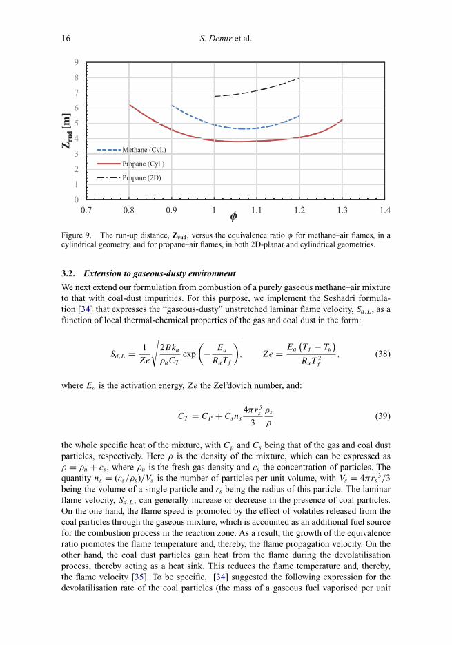
Figure 9. The run-up distance, Zrud, versus the equivalence ratio φ for methane–air flames, in acylindrical geometry, and for propane–air flames, in both 2D-planar and cylindrical geometries.
3.2. Extension to gaseous-dusty environment
We next extend our formulation from combustion of a purely gaseous methane–air mixtureto that with coal-dust impurities. For this purpose, we implement the Seshadri formula-tion [34] that expresses the “gaseous-dusty” unstretched laminar flame velocity, Sd,L, as afunction of local thermal-chemical properties of the gas and coal dust in the form:
Sd,L = 1
Ze
√2Bku
ρuCT
exp
(− Ea
RuTf
), Ze = Ea
(Tf − Tu
)RuT
2f
, (38)
where Ea is the activation energy, Ze the Zel’dovich number, and:
CT = CP + Csns
4πr3s
3
ρs
ρ(39)
the whole specific heat of the mixture, with Cp and Cs being that of the gas and coal dustparticles, respectively. Here ρ is the density of the mixture, which can be expressed asρ = ρu + cs , where ρu is the fresh gas density and cs the concentration of particles. Thequantity ns = (cs/ρs)/Vs is the number of particles per unit volume, with Vs = 4πrs
3/3being the volume of a single particle and rs being the radius of this particle. The laminarflame velocity, Sd,L, can generally increase or decrease in the presence of coal particles.On the one hand, the flame speed is promoted by the effect of volatiles released from thecoal particles through the gaseous mixture, which is accounted as an additional fuel sourcefor the combustion process in the reaction zone. As a result, the growth of the equivalenceratio promotes the flame temperature and, thereby, the flame propagation velocity. On theother hand, the coal dust particles gain heat from the flame during the devolatilisationprocess, thereby acting as a heat sink. This reduces the flame temperature and, thereby,the flame velocity [35]. To be specific, [34] suggested the following expression for thedevolatilisation rate of the coal particles (the mass of a gaseous fuel vaporised per unit
Combustion Theory and Modelling 17
volume per second):
w′v = Ans4π r2T N
s . (40)
In this study, we use A = 3.4 · 10−5kg m–2 s–1 K–1, N = 1.33 as in [34]. The tempera-ture of a coal particle is approximated as Ts = (Tv + Tb)/2, where Tv is the devolatilisationtemperature, which is taken here to be 600 K, and Tb is the adiabatic flame temperaturebased on the purely methane–air equivalence ratio. Among various methods to find Tb, hereit is evaluated as a fifth-order polynomial function of the equivalence ratio [36]:
Tb = (−2.21 × 10⁴)φ5 + (8.042 × 10⁴)φ4 + (−1.171 × 10⁵)φ3
+(8.471 × 10⁴)φ2 + (−2.854 × 10⁴)φ + 4.89 × 10³ , (41)
valid in the range 0.6 ≤ φ ≤ 1.6. The characteristic time of vaporisation is of the orderof [34]:
tr = ku
ρuS2LCT
, (42)
which is the residence time of a coal particle before it enters the reaction zone. It is noted thatSL in Equation (42) is actually the laminar propagation velocity of a gaseous flame (withoutparticles) for a given equivalence ratio, and this quantity can be calculated by removing thecoal dust particles in Equation (39), i.e. by substituting CT = Cp in Equation (38). In ourcase, to match the calculated laminar flame velocity in the case of no particles, we simplytake the experimental values of SL given in Table 2. The characteristic time of vaporisation,tr, is used to estimate the total mass of released volatiles per unit volume, wv = w′
vtr .Similar to [34], for simplicity, this additional fuel is assumed to be methane (CH4), whichis added to the original gaseous methane–air mixture, thereby promoting the equivalenceratio. The new amount of gaseous fuel per unit volume in the mixture is designated asmm
f uel = mmCH4
+ wv , where mmCH4
is the original mass of methane per unit volume for agiven equivalence ratio, and it can be calculated together with that for air as:
mmCH4
= MCH4VCH4P
RuTu
(VCH4 + Vair
) , mmair = MairVairP
RuTu
(VCH4 + Vair
) . (43)
Here P is the atmospheric pressure, VCH4 and Vair , MCH4 and Mair are the volumes andmolar masses of methane and air, respectively. Accordingly, the modified equivalence ratiocan be estimated as:
φs =
[(mm
f uel/MCH4
)/(mm
air/Mair
)]act[(
mmCH4
/MCH4
)/(mm
air/Mair
)]st
. (44)
With this modified equivalence ratio, a new flame temperature, T ∗f , is estimated by
Equation (41). The outcome for a methane–air premixed flame is shown in Figure 13(a),where T ∗
f is presented versus the coal dust concentration cs for various equivalence ratios,φ = 0.7; 0.8; 0.9; 1. To match the experimental values of Table 2 in the case of no

18 S. Demir et al.
Figure 10. The flame temperature T ∗f (a) and laminar velocity S∗
d,L (b) modified by the promotionof the equivalence ratio, versus the particle concentration cs for the particles of size rs = 25 µm.
coal-dust particles, we modify Equation (38) as:
Sd,L = SL
√φs
φ
√CP
CT
(Tf
Tb
)2 (Tb − Tu
Tf − Tu
) √E
(Tf − Tb
)Tf TbRu
. (45)
The corresponding values of T ∗f are then used to estimate the new laminar flame
velocity, S∗d,L, by substituting T ∗
f instead of Tf into Equation (45). The results are shownin Figure 10 for particles of radius rs = 25 µm. Table 4 [37] presents other values used inthe present analysis. It is seen that both T ∗
f and S∗d,L grow with the increase in cs and/or
φ. It is also noted that while the new flame temperature and laminar flame velocity growsignificantly with cs for lean combustion, φ = 0.7, these cs-dependences weaken with theincrease in φ such that T ∗
f and S∗d,L appear almost cs-invariant for φ = 1. This is due to an
effective promotion of the equivalence ratio at φ = 0.7 resulting from the increase in theflame temperature T ∗
f .Unlike a combustible (e.g. coal) particle, an inert (e.g. sand) particle acts only as a heat
sink, because it absorbs heat from the flame and reduces the flame temperature. For lean(φ < 1) or stoichiometric (φ = 1) methane–air combustion, the global chemical reactionreads:
φCH4 + 2 (O2 + 3.76N2) ⇒ φCO2 + 2φH2O + 7.52N2 + 4 (1 − φ) O2. (46)
The heat release in the process of burning of φ moles of methane and 9.52 moles of airequals [(Tb − Tu)
∑CP .nproduct ]. With the assumption that the entire heat released in the
reaction is used to raise the temperature of the mixture, the volumetric heat release from
Table 4. Some physical parameters used in the study [37].
B (s−1) 3.5 × 10⁶ ρu (kg m–3) 1.135ku (W K–1 m–1) 0.052 ρs (kg m–3) 1000E (kJ mol–1) 88.8 Cp (kJ kg–1 K–1) 2.22Ru (kJ mol–1 K) 8.314 × 10⁻³ Cs (kJ kg–1 K–1) 1.26
Combustion Theory and Modelling 19
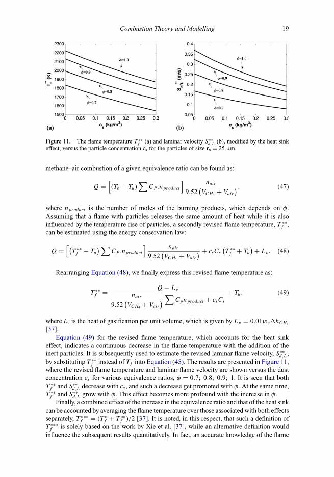
Figure 11. The flame temperature T ∗∗f (a) and laminar velocity S∗∗
d,L (b), modified by the heat sinkeffect, versus the particle concentration cs for the particles of size rs = 25 µm.
methane–air combustion of a given equivalence ratio can be found as:
Q =[(Tb − Tu)
∑CP .nproduct
] nair
9.52(VCH4 + Vair
) , (47)
where nproduct is the number of moles of the burning products, which depends on φ.Assuming that a flame with particles releases the same amount of heat while it is alsoinfluenced by the temperature rise of particles, a secondly revised flame temperature, T ∗∗
f ,can be estimated using the energy conservation law:
Q =[(
T ∗∗f − Tu
)∑CP .nproduct
] nair
9.52(VCH4 + Vair
) + csCs
(T ∗∗
f + Tu
) + Lv. (48)
Rearranging Equation (48), we finally express this revised flame temperature as:
T ∗∗f = Q − Lv
nair
9.52(VCH4 + Vair
) ∑Cpnproduct + csCs
+ Tu, (49)
where Lv is the heat of gasification per unit volume, which is given by Lv = 0.01wv�hCH4
[37].Equation (49) for the revised flame temperature, which accounts for the heat sink
effect, indicates a continuous decrease in the flame temperature with the addition of theinert particles. It is subsequently used to estimate the revised laminar flame velocity, S∗∗
d,L,by substituting T ∗∗
f instead of Tf into Equation (45). The results are presented in Figure 11,where the revised flame temperature and laminar flame velocity are shown versus the dustconcentration cs for various equivalence ratios, φ = 0.7; 0.8; 0.9; 1. It is seen that bothT ∗∗
f and S∗∗d,L decrease with cs , and such a decrease get promoted with φ. At the same time,
T ∗∗f and S∗∗
d,L grow with φ. This effect becomes more profound with the increase in φ.Finally, a combined effect of the increase in the equivalence ratio and that of the heat sink
can be accounted by averaging the flame temperature over those associated with both effectsseparately, T ∗∗∗
f = (T ∗f + T ∗∗
f )/2 [37]. It is noted, in this respect, that such a definition ofT ∗∗∗
f is solely based on the work by Xie et al. [37], while an alternative definition wouldinfluence the subsequent results quantitatively. In fact, an accurate knowledge of the flame
20 S. Demir et al.
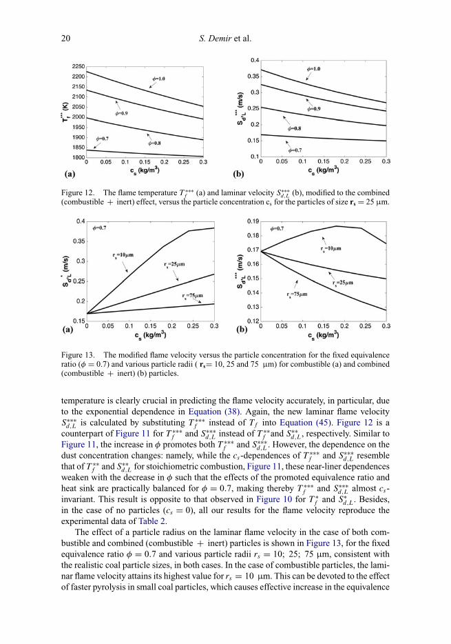
Figure 12. The flame temperature T ∗∗∗f (a) and laminar velocity S∗∗∗
d,L (b), modified to the combined(combustible + inert) effect, versus the particle concentration cs for the particles of size rs = 25 µm.
Figure 13. The modified flame velocity versus the particle concentration for the fixed equivalenceratio (φ = 0.7) and various particle radii ( rs= 10, 25 and 75 µm) for combustible (a) and combined(combustible + inert) (b) particles.
temperature is clearly crucial in predicting the flame velocity accurately, in particular, dueto the exponential dependence in Equation (38). Again, the new laminar flame velocityS∗∗∗
d,L is calculated by substituting T ∗∗∗f instead of Tf into Equation (45). Figure 12 is a
counterpart of Figure 11 for T ∗∗∗f and S∗∗∗
d,L instead of T ∗∗f and S∗∗
d,L, respectively. Similar toFigure 11, the increase in φ promotes both T ∗∗∗
f and S∗∗∗d,L. However, the dependence on the
dust concentration changes: namely, while the cs-dependences of T ∗∗∗f and S∗∗∗
d,L resemblethat of T ∗∗
f and S∗∗d,L for stoichiometric combustion, Figure 11, these near-liner dependences
weaken with the decrease in φ such that the effects of the promoted equivalence ratio andheat sink are practically balanced for φ = 0.7, making thereby T ∗∗∗
f and S∗∗∗d,L almost cs-
invariant. This result is opposite to that observed in Figure 10 for T ∗f and S∗
d,L. Besides,in the case of no particles (cs = 0), all our results for the flame velocity reproduce theexperimental data of Table 2.
The effect of a particle radius on the laminar flame velocity in the case of both com-bustible and combined (combustible + inert) particles is shown in Figure 13, for the fixedequivalence ratio φ = 0.7 and various particle radii rs = 10; 25; 75 µm, consistent withthe realistic coal particle sizes, in both cases. In the case of combustible particles, the lami-nar flame velocity attains its highest value for rs = 10 µm. This can be devoted to the effectof faster pyrolysis in small coal particles, which causes effective increase in the equivalence
Combustion Theory and Modelling 21
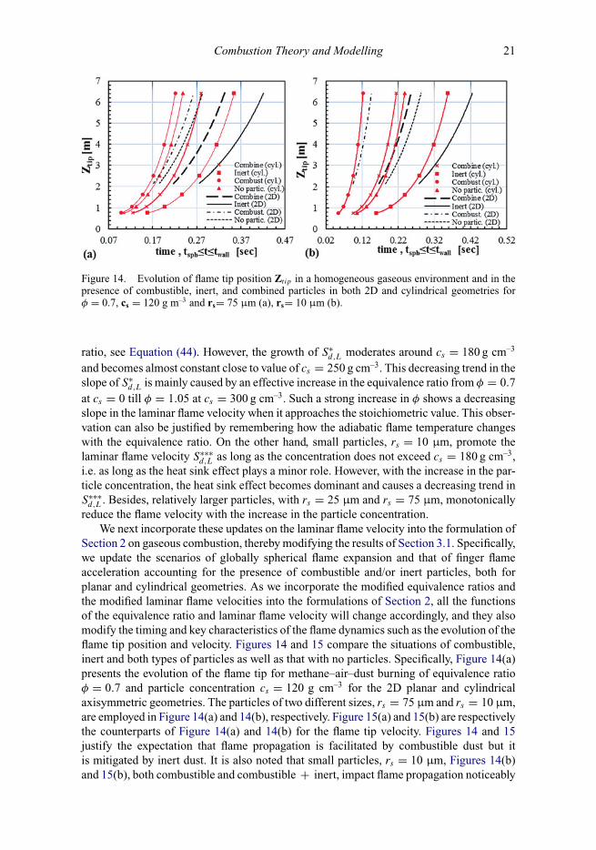
Figure 14. Evolution of flame tip position Zt ip in a homogeneous gaseous environment and in thepresence of combustible, inert, and combined particles in both 2D and cylindrical geometries forφ = 0.7, cs = 120 g m–3 and rs= 75 µm (a), rs= 10 µm (b).
ratio, see Equation (44). However, the growth of S∗d,L moderates around cs = 180 g cm–3
and becomes almost constant close to value of cs = 250 g cm–3. This decreasing trend in theslope of S∗
d,L is mainly caused by an effective increase in the equivalence ratio from φ = 0.7at cs = 0 till φ = 1.05 at cs = 300 g cm–3. Such a strong increase in φ shows a decreasingslope in the laminar flame velocity when it approaches the stoichiometric value. This obser-vation can also be justified by remembering how the adiabatic flame temperature changeswith the equivalence ratio. On the other hand, small particles, rs = 10 µm, promote thelaminar flame velocity S∗∗∗
d,L as long as the concentration does not exceed cs = 180 g cm–3,i.e. as long as the heat sink effect plays a minor role. However, with the increase in the par-ticle concentration, the heat sink effect becomes dominant and causes a decreasing trend inS∗∗∗
d,L . Besides, relatively larger particles, with rs = 25 µm and rs = 75 µm, monotonicallyreduce the flame velocity with the increase in the particle concentration.
We next incorporate these updates on the laminar flame velocity into the formulation ofSection 2 on gaseous combustion, thereby modifying the results of Section 3.1. Specifically,we update the scenarios of globally spherical flame expansion and that of finger flameacceleration accounting for the presence of combustible and/or inert particles, both forplanar and cylindrical geometries. As we incorporate the modified equivalence ratios andthe modified laminar flame velocities into the formulations of Section 2, all the functionsof the equivalence ratio and laminar flame velocity will change accordingly, and they alsomodify the timing and key characteristics of the flame dynamics such as the evolution of theflame tip position and velocity. Figures 14 and 15 compare the situations of combustible,inert and both types of particles as well as that with no particles. Specifically, Figure 14(a)presents the evolution of the flame tip for methane–air–dust burning of equivalence ratioφ = 0.7 and particle concentration cs = 120 g cm–3 for the 2D planar and cylindricalaxisymmetric geometries. The particles of two different sizes, rs = 75 µm and rs = 10 µm,are employed in Figure 14(a) and 14(b), respectively. Figure 15(a) and 15(b) are respectivelythe counterparts of Figure 14(a) and 14(b) for the flame tip velocity. Figures 14 and 15justify the expectation that flame propagation is facilitated by combustible dust but itis mitigated by inert dust. It is also noted that small particles, rs = 10 µm, Figures 14(b)and 15(b), both combustible and combustible + inert, impact flame propagation noticeably

22 S. Demir et al.
Figure 15. Evolution of flame tip position Utip in a homogeneous gaseous environment and in thepresence of combustible, inert, and combined particles in both 2D and cylindrical geometries forφ = 0.7, cs = 120 g m–3 and rs= 75 µm (a), rs= 10 µm (b).
stronger than that of rs = 75 µm, Figures 14(a) and 15(a). In particular, while the differencebetween the cases of no particles and combustible particles is hardly seen for rs = 75 µmin the cylindrical geometry, such a difference is substantial for rs = 10 µm, both in the2D planar and cylindrical axisymmetric configurations. The difference between the casesof no particles and that of combined particles becomes relatively small in the cylindricalgeometry. Additionally, in line with Section 3.1, the flame tip velocity attains higher valuesfor all (combustible, inert, combined combustible + inert and no particles) cases in thecylindrical geometry as compared to a 2D one, hence yielding faster flame propagation.Such a qualitative and quantitative difference is demonstrated in Figures 14 and 15.
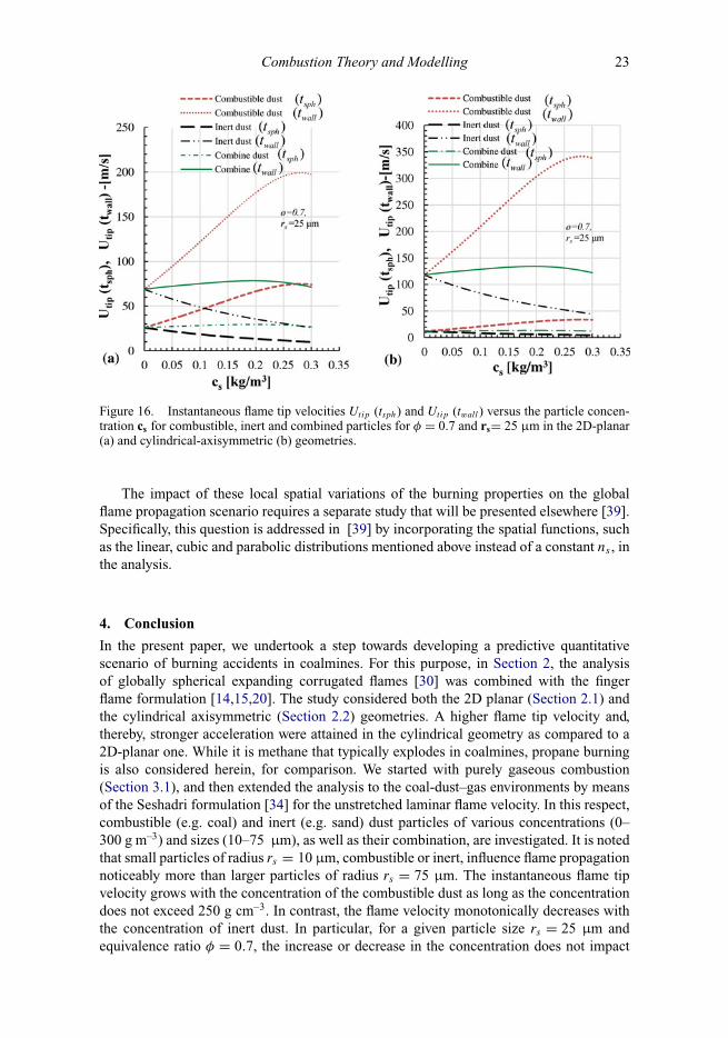
We have also investigated the effect of particles concentration on the instantaneousflame tip velocity Utip(tsph, twall) for the combustible, inert and combined combustible +inert dust for the equivalence ratio φ = 0.7 and the particle radius rs = 25 µm. The resultis shown in Figure 16, for the 2D (a) and cylindrical (b) geometries. Specifically, the flametip velocities attained at the time instants tsph and twall increase with the concentrationof the combustible dust as long as the cs < 250 g cm–3. In contrast, the flame tip velocitydiminishes with the concentration of the inert dust. For a given particle size and equivalenceratio, the increase or decrease in the combined particles concentration does not influenceUtip(tsph). For the same particle type, Utip(twall) slightly increases with the concentrationwhile cs < 200 g cm–3 but then decreases when cs > 200 g cm–3.
Finally, it is noted that different motions of dust participles may influence the fireevolution. Moreover, distribution of the particle velocities will lead to a non-uniformdistribution of the dust concentration and thereby a certain spatial distribution of the localburning properties such as that of equivalence ratio φs , laminar flame velocity Sd,L, etc. Infact, the coal dust distribution is typically non-uniform in coalmines and a stationary densecoal dust layer may spread through the bottom of the channel. In particular, a gaseous-baseddetonation wave may produce a strong shock that can lift and entrain the dust layer. Overtime, the shock weakens but the shock-heated fluid is ignited by lifted dust, which initiatesa secondary combustion process [38]. Such a lifted dust layer may resemble a linear, cubic,or even parabolic distribution of the dust concentration in space, due to the different energylevels of complex magnetic forces.
Combustion Theory and Modelling 23
Figure 16. Instantaneous flame tip velocities Utip (tsph) and Utip (twall) versus the particle concen-tration cs for combustible, inert and combined particles for φ = 0.7 and rs= 25 µm in the 2D-planar(a) and cylindrical-axisymmetric (b) geometries.
The impact of these local spatial variations of the burning properties on the globalflame propagation scenario requires a separate study that will be presented elsewhere [39].Specifically, this question is addressed in [39] by incorporating the spatial functions, suchas the linear, cubic and parabolic distributions mentioned above instead of a constant ns , inthe analysis.
4. Conclusion
In the present paper, we undertook a step towards developing a predictive quantitativescenario of burning accidents in coalmines. For this purpose, in Section 2, the analysisof globally spherical expanding corrugated flames [30] was combined with the fingerflame formulation [14,15,20]. The study considered both the 2D planar (Section 2.1) andthe cylindrical axisymmetric (Section 2.2) geometries. A higher flame tip velocity and,thereby, stronger acceleration were attained in the cylindrical geometry as compared to a2D-planar one. While it is methane that typically explodes in coalmines, propane burningis also considered herein, for comparison. We started with purely gaseous combustion(Section 3.1), and then extended the analysis to the coal-dust–gas environments by meansof the Seshadri formulation [34] for the unstretched laminar flame velocity. In this respect,combustible (e.g. coal) and inert (e.g. sand) dust particles of various concentrations (0–300 g m–3) and sizes (10–75 µm), as well as their combination, are investigated. It is notedthat small particles of radius rs = 10 µm, combustible or inert, influence flame propagationnoticeably more than larger particles of radius rs = 75 µm. The instantaneous flame tipvelocity grows with the concentration of the combustible dust as long as the concentrationdoes not exceed 250 g cm–3. In contrast, the flame velocity monotonically decreases withthe concentration of inert dust. In particular, for a given particle size rs = 25 µm andequivalence ratio φ = 0.7, the increase or decrease in the concentration does not impact

24 S. Demir et al.
the flame velocity due to a balance between the effects of the equivalence ratio and the heatsink.
We have predicted and quantified the key stages and characteristics of coalmine burningsuch as the evolution and velocity of the tip and skirt of the flame front as well as the locusand timing of a potential detonation onset. The timing for each stage as well as the flameshapes, propagation speeds, acceleration rates, run-up distances and flame-generated veloc-ity profiles were identified. Specifically, when an accidental ignition occurs in a coalmine,first, an embryonic flame develops from a smooth hemispherical/hemi-circular kernel to aglobally spherical/cellular (corrugated) structure. This occurs due to the Darrieus–Landauflame instability, and the process is accompanied by self-similar flame acceleration. Sub-sequently, such a cellular flame acquires a finger-like shape, exhibiting strong acceleration,which lasts for a short time, until a flame skirts contacts a passage wall. In particular, ina 2D geometry, no detonation is predicted for methane combustion, while in the case ofpropane, the detonation may occur for near-stoichiometric, slightly fuel-rich burning, withequivalence ratios in the range 1 ≤ φ ≤ 1.2. For the cylindrical geometry, this range variesas 0.9 ≤ φ ≤ 1.2 and 0.8 ≤ φ ≤ 1.3 for methane and propane, respectively.
The entire acceleration scenario may promote the total burning rate by up to twoorders of magnitude, to near-sonic flame velocities. Obviously, such fast flame spreadingconstitutes a substantial disaster, especially in enclosures and limited spacing such as incoalmines. Moreover, in addition to the direct disaster of such a fast flame, it may facilitatethe deflagration-to-detonation transition, thereby leading to additional hazards for bothpersonnel and equipment such as spreading of strong shock waves.
AcknowledgmentsThe co-authors recognise Vitaly Bychkov, who passed away when the work was in progress.
Disclosure statementNo potential conflict of interest was reported by the authors.
FundingThis study is sponsored by the US National Science Foundation (NSF) [through the CAREER Award#1554254] (V.A.), prior to which it was supported by the Alpha Foundation for the Improvement ofMine Safety and Health, Inc. (ALPHA FOUNDATION) [through the Award #AFSTI14-05] (V.A.)as well as West Virginia University’s Program to Stimulate Competitive Research (PSCoR) andWest Virginia University’s Senate Award for Research and Scholarship. The views, opinions andrecommendations expressed herein are solely those of the authors and do not imply any endorsementby the ALPHA FOUNDATION, its directors and staff.
References[1] K. Chatrathi, J.E. Going, and B. Grandestaff, Flame propogation in industrial scale piping,
Process Saf. Prog. 20 (4) (2001), pp. 286–294.[2] M. Silvestrini, B. Genova, G. Parisi, and F.L. Trujillo, Flame acceleration and DDT run-up
distance for smooth and obstacles filled tubes, J. Loss Prev. Process Ind. 21 (2008), pp. 555–562.[3] X. Chen, Y. Zhang, and Y. Zhang, Effect of CH4-air ratios on gas explosion flame microstructure
and propogation behaviors, Energies 5 (2012), pp. 4132–4146.[4] M. Bi, C. Dong, and Y. Zhou, Numerical simulation of premixed methane-air deflagration in
large L/D closed pipes, Appl. Therm. Eng. 40 (2012), pp. 337–342.[5] L. Kjaldman, Numerical flow simulation of dust deflegration, Power Technol. 71 (1992), pp.
163–169.

Combustion Theory and Modelling 25
[6] Q. Liu, C. Bai, X. Li, L. Jiang, and W. Dai, Coal dust/air explosions in a large-scale tube, Fuel89 (2010), pp. 329–335.
[7] T. Skjold, D. Castellanos, K. Olsen, and R. Eckhoff, Experimental and numerical investigationof constant volume dust and gas explosions in a 3,6-m flame acceleration tube, J. Loss Prev.Process Ind. 30 (2014), pp. 164–176.
[8] R.W. Houim and E.S. Oran, Structure and flame speed speed of dilute and dense layeredcoal-dust explosions, J. Loss Prev. Process Ind. 36 (2015), pp. 214–222.
[9] B. Gardner, R. Winter, and M. Moore, Explosion development and deflegration to detonationin coal dust/air suspensions, Proc. Combust. Inst. 21 (1986), pp. 335–343.
[10] W. Bartknecht, Bundesinstitut fur Arbeitsschutz (Bifa), Koblenz, Germany, 1971.[11] W. Bartknecht, Staubexplosionen, Springer, Verlag, 1987.[12] A.K. Oppenheim, A.J. Laderman, and P.A. Urtiew, The onset of retonation, Combust. Flame 6
(1962), pp. 193–197.[13] P.A. Urtiew and A.K. Oppenheim, Experimental observations of the transition to detonation
in an explosive gas, Proc R. Soc. Lond. Ser. A. Math. Phys. 295 (1940) (1966), pp. 13–28.[14] C. Clanet and G. Searby, On the “tulip flame” phenomenon, Combust. Flame 105 (1996), pp.
225–238.[15] V. Bychkov, V. Akkerman, G. Fru, A. Petchenko, and L.E. Eriksson, Flame acceleration in the
early stages of burning in tubes, Combust. Flame 150 (2007), pp. 263–276.[16] H. Xiao, R.W. Houim, and E.S. Oran, Formation and evolution of distorted tulip flames,
Combust. Flame 162 (11) (2015), pp. 4084–4101.[17] V. Bychkov and M. Liberman, Dynamics and stability of premixed flames, Phys. Rep. 325
(2000), pp. 115–237.[18] D. Bradley, T.M. Cresswell, and J.S. Puttock, Flame acceleration due to flame-induced insta-
bilities in large-scale explosions, Combust. Flame 124 (4) (2001), pp. 551–559.[19] T. Becker and F. Ebert, Vergleich zwischen experiment und theorie der explosion grober, freier
gaswolken, Chem. Ing. Tech. 57 (1) (1985), pp. 42–45.[20] D. Valiev, V. Akkerman, M. Kuznetsov, L.E. Eriksson, C.K. Law, and V. Bychkov, Influence of
gas compression on flame acceleration in the early stage of burning in tubes, Combust. Flame160 (2013), pp. 97–111.
[21] V. Bychkov, A. Petchenko, V. Akkerman, and L.E. Eriksson, Theory and modelling of acceler-ating flames in tubes, Phys. Rev. E. 72 (2005), p. 046307.
[22] D. Valiev, V. Bychkov, V. Akkerman, and A. Petchenko, Flame acceleration in channels withobstacles in the deflegration-to-detonation transition, Combust. Flame 157 (2010), pp. 1012–1021.
[23] V. Akkerman and V. Bychkov, Turbulent flame and the Darrieus-Landau instability in a three-dimensional flow, Combust. Theory Modelling 7 (2003), pp. 767–794.
[24] M.A. Liberman, M.F. Ivanov, A.D. Kiverin, M.S. Kuznetsov, A.A. Chukalovsky, and T.V.Rakhimova, Deflegration-to-detonation transition in highly reactive combustible mixtures, ActaAstronaut. 67 (2010), pp. 688–701.
[25] V. Akkerman, V. Bychkov, A. Petchenko, and L.E. Eriksson, Accelerating flames in cylindricaltubes with nonslip at the walls, Combust. Flame 145 (2006), pp. 206–219.
[26] Z. Chen and Y. Ju, Theoretical analysis of the evolution from ignation kernel to flame ball andplanar flame, Combust. Theory Modelling 11 (3) (2007), pp. 427–453.
[27] M. Burke, Z. Chen, Y. Ju, and F. Dryer, Effect of cylindrical confinement on the determinationof laminar flame speeds using outwardly propagating flames, Combust. Flame 156 (4) (2009),pp. 771–779.
[28] C.K. Law, Combustion Physics, Cambridge University Press, New York, 2006.[29] Y.B. Zeldovich, G.I. Barenblatt, V.B. Librovich, and G.M. Makhviladze, Mathematical Theory
of Combustion and Explosion, Consultants Bureau, New York, 1985.[30] V. Akkerman, C.K. Law, and V. Bychkov, Self-similar accelerative propagation of expanding
wrinkled flames and explosion triggering, Phys. Rev. E. 83 (2011), p. 026305.[31] V. Bychkov and M. Liberman, Stability and fractal structure of a spherical flame in a self-similar
regime, Phys. Rev. Lett. 76 (1996), pp. 2814–2817.[32] P. Pelce and P. Clavin, Influence of hydrodynamics and diffusion upon the stability limits of
laminar premixed flames, J. Fluid Mech. 124 (1982), pp. 219–237.[33] S.G. Davis, J. Quinard, and G. Searby, Markstein numbers in counterflow methane- and
propane-air flames: A computational study, Combust. Flame 7 (2003), pp. 767–794.

26 S. Demir et al.
[34] K. Seshadri, A.L. Berlad, and V. Tangirala, The structure of premixed particle-cloud flames,Combust. Flame 89 (1992), pp. 333–342.
[35] S. Ranganathan, M. Lee, V. Akkerman, and A.S. Rangwala, Suppression of premixed flameswith inert particles, J. Loss Prev. Process Ind. 35 (2015), pp. 46–51.
[36] C. Morley, Gaseq, (2005), [Online]. Available at http://www.c.morley.dsl.pipex.com/.[37] Y. Xie, V. Raghavan, and A.S. Rangwala, Study of interaction of entrained coal dust particles
in lean methane-air premixed flames, Combust. Flame 159 (2012), pp. 2449–2456.[38] R.W. Houim and E.S. Oran, Numerical simulation of dilute and dense layered coal-dust explo-
sions, Proc. Combust. Inst. 35 (2015), pp. 2083–2090.[39] S. Demir, H. Sezer, and V. Akkerman, Effect of local variations of the laminar flame speed on
the global finger-flame acceleration scenario, Combust. Sci. Technol. submitted.


![Influence of gas compressibility on a burning accident in a ...€¦ · which may identify the applicability and limitations of the incompressible theory [6]. For simplicity, here](https://img.dokumen.tips/doc/110x75/5f0f4f6a7e708231d4438705/iniuence-of-gas-compressibility-on-a-burning-accident-in-a-which-may-identify.jpg)