Embed Size (px)
Citation preview
Preface, Contents
Introduction 1
Functionality 2
Commissioning 3
Operating the TP 170A 4
Operation of Screen Objects 5
System Settings 6
Installation 7
Unit Description 8
Maintenance/Upkeep 9
Operating System Update 10
Appendices
A
E
Glossary, Index
Release 12/99
6AV6591–1DC11–0AB0
Touch PanelTP 170A
Equipment Manual
SIMATIC HMI
Index-2TP 170A Equipment Manual
Release 12/99
!Warning
indicates that death, severe personal injury or substantial property damage can result if proper precau-tions are not taken.
!Caution
indicates that minor personal injury or property damage can result if proper precautions are not taken.
Note
draws your attention to particularly important information on the product, handling the product, or to aparticular part of the documentation.
Qualified PersonnelEquipment may be commissioned and operated only by qualified personnel . Qualified personnel withinthe meaning of the safety notices in this manual are persons who are authorized to commission, groundand identify equipment, systems and circuits in accordance with safety engineering standards.
Correct UsageNote the following:
!Warning
The equipment may be used only for the applications stipulated in the catalog and in the technical descrip-tion and only in conjunction with other equipment and components recommended or approved by Sie-mens.
Startup must not take place until it is established that the machine, which is to accommodate this compo-nent, is in conformity with the guideline 89/392/EEC.
Faultless and safe operation of the product presupposes proper transportation, proper storage, erectionand installation as well as careful operation and maintenance.
TrademarksThe registered trademarks of Siemens AG are listed in the Preface.
Some of the other designations used in these documents are also registered trademarks; the owner’srights may be violated if they are used be third parties for their own purposes.
ImpressumEditor and Publisher: A&D PT1 D1.
Safety GuidelinesThis manual contains notices which you should observe to ensure your own personal safety, as well as toprotect the product and connected equipment. These notices are highlighted in the manual by a warningtriangle and are marked as follows according to the level of danger:
We have checked the contents of this manual for agreement with the hard-ware and software described. Since deviations cannot be precluded entirely,we cannot guarantee full agreement. However, the data in this manual arereviewed regularly and any necessary corrections included in subsequenteditions. Suggestions for improvement are welcomed.
Disclaimer of LiabilityCopyright Siemens AG 1999 All rights reserved
The reproduction, transmission or use of this document or its contents is notpermitted without express written authority. Offenders will be liable fordamages. All rights, including rights created by patent grant or registration ofan utility model or design, are reserved.
Siemens AGBereich Automatisierungs- und AntriebstechnikBedienen und BeobachtenPostfach 4848, D-90327 Nuernberg
� Siemens AG 1999Technical data subject to change.
Siemens Aktiengesellschaft Order no: 6AV6591–1DC11–0AB0
iTP 170A Equipment ManualRelease 12/99
Preface
This manual
The TP 170A equipment manual is part of the SIMATIC HMI documentation. Itprovides operation, installation, configuration and system personnel withinformation concerning installation, functionality, operation and technical design ofthe TP 170A.
An overview of the entire SIMATIC HMI documentation is provided in Appendix E.
Organization of the manual
The TP 170A equipment manual is organized into the following chapters:
Chapter Contents
1 - 2 Overview of features and functional scope of the TP 170A.
3 - 6 Commissioning, operation and system settings.
7 - 9 Mechanical and electrical installation, unit description, as well asmaintenance and upkeep of the TP 170A.
10 Information on the operating system update.
Appendix � Technical Data
� Interface Assignments
� System Messages
� ESD Guidelines
� SIMATIC HMI Documentation
Preface
iiTP 170A Equipment Manual
Release 12/99
Conventions
The following conventions are used throughout this manual:
Motor off Text in the operating unit display is presented in thistypewriter font.
Tag Symbolic names representing tag values on the screen arepresented in this italic typewriter font.
Screens Functions available for selection are presented in this italicfont.
ESC The names of keys and buttons are displayed in a differentfont.
History
The various releases of this manual correspond to the following versions of theProTool configuration software:
Release Comment ProTool version
12/99 First release of the TP 170A equipmentmanual.
From Vers. 5.2
Trademarks
The following names are registered trademarks of the Siemens AG:
� SIMATIC�
� SIMATIC HMI�
� HMI�
� ProTool�
� ProTool/Lite�
� ProTool/Pro�
� SIMATIC Multi Panel�
� SIMATIC Multifunctional Platform�
� MP 270�
� ProAgent�
Other support
In the case of technical queries, please contact the Siemens representatives in thesubsidiaries and branches responsible for your area.
Preface
iiiTP 170A Equipment ManualRelease 12/99
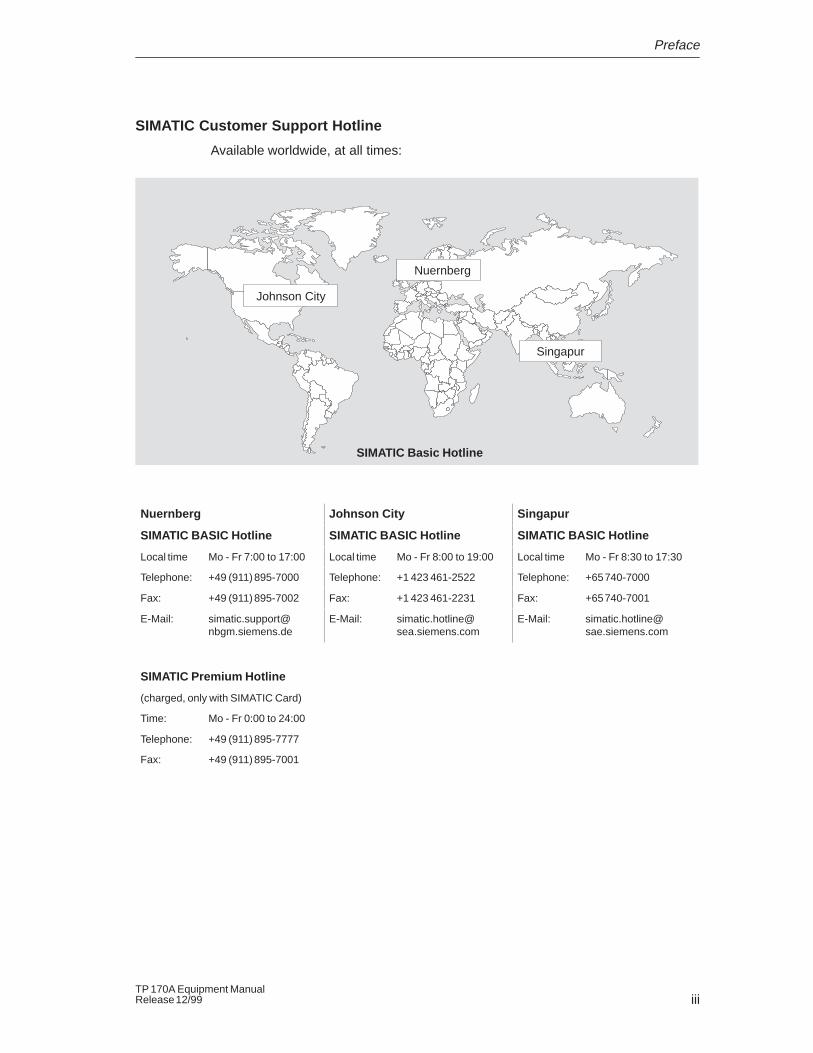
SIMATIC Customer Support Hotline
Available worldwide, at all times:
Johnson City
Nuernberg
Singapur
SIMATIC Basic Hotline
Nuernberg Johnson City Singapur
SIMATIC BASIC Hotline SIMATIC BASIC Hotline SIMATIC BASIC Hotline
Local time Mo - Fr 7:00 to 17:00 Local time Mo - Fr 8:00 to 19:00 Local time Mo - Fr 8:30 to 17:30
Telephone: +49 (911) 895-7000 Telephone: +1 423 461-2522 Telephone: +65 740-7000
Fax: +49 (911) 895-7002 Fax: +1 423 461-2231 Fax: +65 740-7001
E-Mail: [email protected]
E-Mail: [email protected]
E-Mail: [email protected]
SIMATIC Premium Hotline
(charged, only with SIMATIC Card)
Time: Mo - Fr 0:00 to 24:00
Telephone: +49 (911) 895-7777
Fax: +49 (911) 895-7001
Preface
ivTP 170A Equipment Manual
Release 12/99
SIMATIC Customer Online Services
SIMATIC Customer Support offers comprehensive additional informationconcerning SIMATIC products through its Online services as follows:
� Up-to-date general information is provided
– in Internet under http://www.ad.siemens.de/simatic
– via the Fax-Polling under 08765–93 02 77 95 00
� Up-to-date product information and downloads for practical use can be found:
– in Internet under http://www.ad.siemens.de/support/html–00/
Preface
vTP 170A Equipment ManualRelease 12/99
Abbreviations
The abbreviations used in this equipment manual have the following meaning:
AG (PLC) Programmable Logic Controller
ANSI American National Standards Institute
AS 511 Protocol of the PU interface to SIMATIC S5
ASCII American Standard Code for Information Interchange
CCFL Cold Cathode Fluorescence Lamp
CF Compact Flash
CPU Central Processing Unit
DIL Dual-In-Line
DP Decentralized Periphery
EM Event Message
EMC Electromagnetic Compatibility
EPROM Electric Programmable Read Only Memory
ESD Electrostatic Sensitive Device
HMI Human Machine Interface
IF Interface
LCD Liquid Crystal Display
LED Light Emitting Diode
MPI Multipoint Interface (SIMATIC S7)
OP Operator Panel
PC Personal Computer
PLC Programmable Logic Control
PPI Point to Point Interface (SIMATIC S7)
PU Programming Unit
RISC Reduced Instruction Set Computing
SRAM Static Random Access Memory
STN Super Twisted Nematic
TP Touch Panel
TTL Transistor–Transistor Logic
A list of all the specialist terms together with their explanations is provided in theGlossary at the end of this manual.

Preface
viTP 170A Equipment Manual
Release 12/99
viiTP 170A Equipment ManualRelease 12/99
Contents
1 Introduction 1-1. . . . . . . . . . . . . . . . . . . . . . . . . . . . . . . . . . . . . . . . . . . . . . . . . . . . . . . . . . . .
2 Functionality 2-1. . . . . . . . . . . . . . . . . . . . . . . . . . . . . . . . . . . . . . . . . . . . . . . . . . . . . . . . . . .
3 Commissioning 3-1. . . . . . . . . . . . . . . . . . . . . . . . . . . . . . . . . . . . . . . . . . . . . . . . . . . . . . . .
3.1 Initial Startup 3-2. . . . . . . . . . . . . . . . . . . . . . . . . . . . . . . . . . . . . . . . . . . . . . . . . . .
3.2 Recommissioning 3-3. . . . . . . . . . . . . . . . . . . . . . . . . . . . . . . . . . . . . . . . . . . . . . .
3.3 Download Mode Options 3-5. . . . . . . . . . . . . . . . . . . . . . . . . . . . . . . . . . . . . . . . .
3.4 Test Configuration 3-7. . . . . . . . . . . . . . . . . . . . . . . . . . . . . . . . . . . . . . . . . . . . . . .
4 Operating the TP 170A 4-1. . . . . . . . . . . . . . . . . . . . . . . . . . . . . . . . . . . . . . . . . . . . . . . . . .
4.1 Operating Touch Elements 4-2. . . . . . . . . . . . . . . . . . . . . . . . . . . . . . . . . . . . . . . .
4.2 Entering Values 4-4. . . . . . . . . . . . . . . . . . . . . . . . . . . . . . . . . . . . . . . . . . . . . . . . .
4.3 Operating Screens 4-6. . . . . . . . . . . . . . . . . . . . . . . . . . . . . . . . . . . . . . . . . . . . . .
5 Operation of Screen Objects 5-1. . . . . . . . . . . . . . . . . . . . . . . . . . . . . . . . . . . . . . . . . . . .
5.1 Overview of Screen Objects 5-2. . . . . . . . . . . . . . . . . . . . . . . . . . . . . . . . . . . . . .
5.2 Status Button 5-3. . . . . . . . . . . . . . . . . . . . . . . . . . . . . . . . . . . . . . . . . . . . . . . . . . .
5.3 Messages 5-5. . . . . . . . . . . . . . . . . . . . . . . . . . . . . . . . . . . . . . . . . . . . . . . . . . . . . .
5.4 Logging On and Off from the Operating Unit 5-7. . . . . . . . . . . . . . . . . . . . . . . .
6 System Settings 6-1. . . . . . . . . . . . . . . . . . . . . . . . . . . . . . . . . . . . . . . . . . . . . . . . . . . . . . . .
6.1 Setting an Operating Mode 6-2. . . . . . . . . . . . . . . . . . . . . . . . . . . . . . . . . . . . . . .
6.2 Screen Settings 6-3. . . . . . . . . . . . . . . . . . . . . . . . . . . . . . . . . . . . . . . . . . . . . . . . .
7 Installation 7-1. . . . . . . . . . . . . . . . . . . . . . . . . . . . . . . . . . . . . . . . . . . . . . . . . . . . . . . . . . . . .
7.1 Mechanical Installation 7-2. . . . . . . . . . . . . . . . . . . . . . . . . . . . . . . . . . . . . . . . . . .
7.2 Electrical Installation 7-4. . . . . . . . . . . . . . . . . . . . . . . . . . . . . . . . . . . . . . . . . . . . . 7.2.1 Connect Configuration Computer 7-7. . . . . . . . . . . . . . . . . . . . . . . . . . . . . . . . . . 7.2.2 Connect PLC 7-8. . . . . . . . . . . . . . . . . . . . . . . . . . . . . . . . . . . . . . . . . . . . . . . . . . .
8 Unit Description 8-1. . . . . . . . . . . . . . . . . . . . . . . . . . . . . . . . . . . . . . . . . . . . . . . . . . . . . . . .
8.1 Dimensions 8-2. . . . . . . . . . . . . . . . . . . . . . . . . . . . . . . . . . . . . . . . . . . . . . . . . . . . .
8.2 Connection Elements 8-3. . . . . . . . . . . . . . . . . . . . . . . . . . . . . . . . . . . . . . . . . . . .
8.3 Communication Options 8-4. . . . . . . . . . . . . . . . . . . . . . . . . . . . . . . . . . . . . . . . . .
Contents
viiiTP 170A Equipment Manual
Release 12/99
9 Maintenance/Upkeep 9-1. . . . . . . . . . . . . . . . . . . . . . . . . . . . . . . . . . . . . . . . . . . . . . . . . . . .
10 Operating System Update 10-1. . . . . . . . . . . . . . . . . . . . . . . . . . . . . . . . . . . . . . . . . . . . . . .
Appendices
A Technical Data A-1. . . . . . . . . . . . . . . . . . . . . . . . . . . . . . . . . . . . . . . . . . . . . . . . . . . . . . . . .
B Interface Assignment B-1. . . . . . . . . . . . . . . . . . . . . . . . . . . . . . . . . . . . . . . . . . . . . . . . . . .
C System Messages C-1. . . . . . . . . . . . . . . . . . . . . . . . . . . . . . . . . . . . . . . . . . . . . . . . . . . . . .
D ESD-Guidelines D-1. . . . . . . . . . . . . . . . . . . . . . . . . . . . . . . . . . . . . . . . . . . . . . . . . . . . . . . .
E SIMATIC HMI Documentation E-1. . . . . . . . . . . . . . . . . . . . . . . . . . . . . . . . . . . . . . . . . . . .
1-1TP 170A Equipment ManualRelease 12/99
Introduction
Use of the TP 170A
The TP 170A is the basic touch panel for all SIMATIC S7 CPUs. It is the first touchpanel unit in the SIMATIC HMI product range and is based on the operating systemMicrosoft� Windows� CE.
The TP 170A is suitable for all basic functions. It has an interface which can be usedfor both the MPI and the Profibus-DP. The unit memory is designed for smallerconfigurations. The objects used for a configuration can be buttons, bar graphs,graphics and messages.
Area of use of the TP 170A
The TP 170A has been conceived for machine operation and monitoring. Itprovides a realistic graphical representation of the machine or system to bemonitored. Its area of use includes implementation in machine and apparatusconstruction as well as in the packing and electronics industry.
The high degree of protection (IP65 on the front side) and non-implementation ofmoving storage media, such as hard disks and floppy disks, ensure the TP 170A isalso suitable for use in rough industrial environments and directly on site on therespective machine.
The TP 170A can be installed in switching cabinets and operating consoles.
Due to the fact that the TP 170A is equipped with high performance basichardware and has a minimum installation depth means that it fulfills all therequirements for operation in the vicinity of the machine.
1
Introduction
1-2TP 170A Equipment Manual
Release 12/99
Easy to operate and observe
The TP 170A enables operating statuses and current process values concerning aconnected PLC to be graphically displayed and the relevant machine or system tobe easily monitored and operated. Display and operation of the TP 170A can beadapted optimally for the respective process requirements by using theconfiguration software ProTool/Lite, ProTool and ProTool/Pro CS (fromVersion 5.2).
The TP 170A can be used to:
� control and monitor the process intuitively. Setpoint values or control elementsettings, for instance, can be modified by entering values or touching configuredbuttons;
� display processes, machines and systems graphically;
� visualize operating and alarm messages and process tags, e.g. in output fields,bar graphs or trend curves;
� intervene directly in the operation by means of the touch-sensitive screen.
Introduction
1-3TP 170A Equipment ManualRelease 12/99
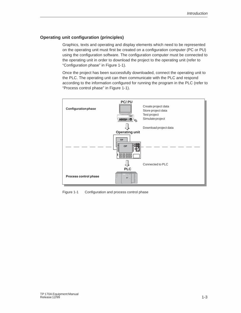
Operating unit configuration (principles)
Graphics, texts and operating and display elements which need to be representedon the operating unit must first be created on a configuration computer (PC or PU)using the configuration software. The configuration computer must be connected tothe operating unit in order to download the project to the operating unit (refer to“Configuration phase” in Figure 1-1).
Once the project has been successfully downloaded, connect the operating unit tothe PLC. The operating unit can then communicate with the PLC and respondaccording to the information configured for running the program in the PLC (refer to“Process control phase” in Figure 1-1).
Create project dataStore project dataTest projectSimulate project
Download project data
Connected to PLC
Configuration phase
������������������
PC/ PU
PLC
Operating unit
TP
OP
Figure 1-1 Configuration and process control phase
Introduction
1-4TP 170A Equipment Manual
Release 12/99
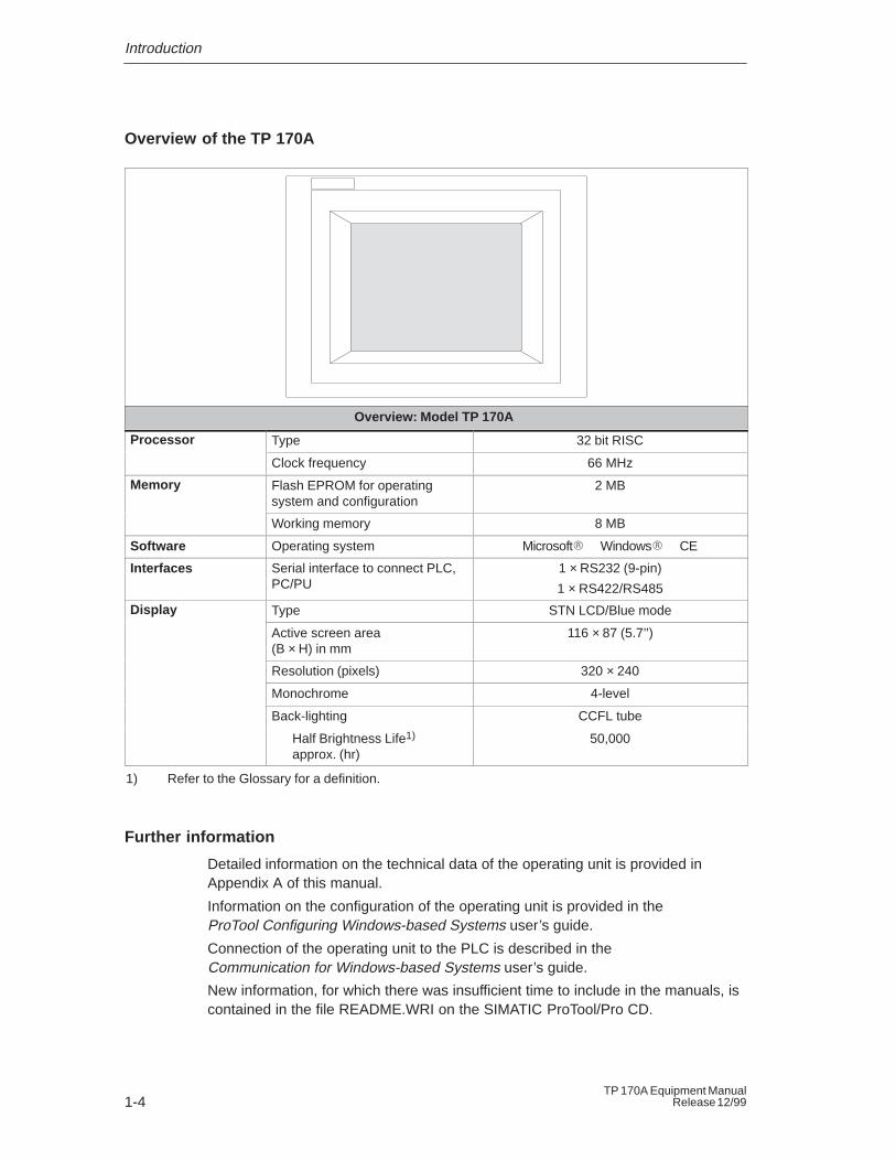
Overview of the TP 170A
Overview: Model TP 170A
Processor Type 32 bit RISC
Clock frequency 66 MHz
Memory Flash EPROM for operatingsystem and configuration
2 MB
Working memory 8 MB
Software Operating system Microsoft�� Windows�� CE
Interfaces Serial interface to connect PLC,PC/PU
1 × RS232 (9-pin)
1 × RS422/RS485
Display Type STN LCD/Blue mode
Active screen area (B × H) in mm
116 × 87 (5.7’’)
Resolution (pixels) 320 × 240
Monochrome 4-level
Back-lighting CCFL tube
Half Brightness Life1) approx. (hr)
50,000
1) Refer to the Glossary for a definition.
Further information
Detailed information on the technical data of the operating unit is provided inAppendix A of this manual.
Information on the configuration of the operating unit is provided in theProTool Configuring Windows-based Systems user’s guide.
Connection of the operating unit to the PLC is described in theCommunication for Windows-based Systems user’s guide.
New information, for which there was insufficient time to include in the manuals, iscontained in the file README.WRI on the SIMATIC ProTool/Pro CD.
2-1TP 170A Equipment ManualRelease 12/99
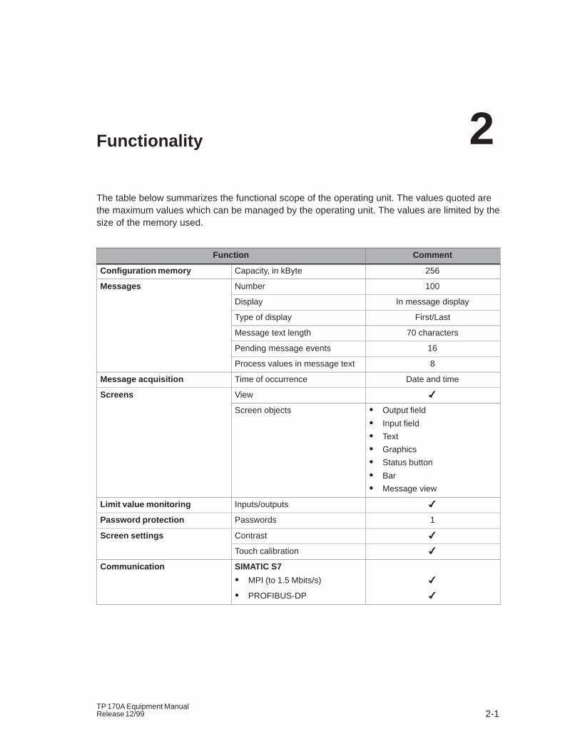
Functionality
The table below summarizes the functional scope of the operating unit. The values quoted arethe maximum values which can be managed by the operating unit. The values are limited by thesize of the memory used.
Function Comment
Configuration memory Capacity, in kByte 256
Messages Number 100
Display In message display
Type of display First/Last
Message text length 70 characters
Pending message events 16
Process values in message text 8
Message acquisition Time of occurrence Date and time
Screens View �
Screen objects � Output field
� Input field
� Text
� Graphics
� Status button
� Bar
� Message view
Limit value monitoring Inputs/outputs �
Password protection Passwords 1
Screen settings Contrast �
Touch calibration �
Communication SIMATIC S7
� MPI (to 1.5 Mbits/s) �
� PROFIBUS-DP �
2

Functionality
2-2TP 170A Equipment Manual
Release 12/99
3-1TP 170A Equipment ManualRelease 12/99
Commissioning
In this chapter
This chapter provides information on:
� starting up the operating unit for the first time (Page 3-2)
� restarting the operating unit (from Page 3-3)
� the options for Download mode (from Page 3-5)
� testing a configuration (Page 3-7)
3
Commissioning
3-2TP 170A Equipment Manual
Release 12/99
3.1 Initial Startup
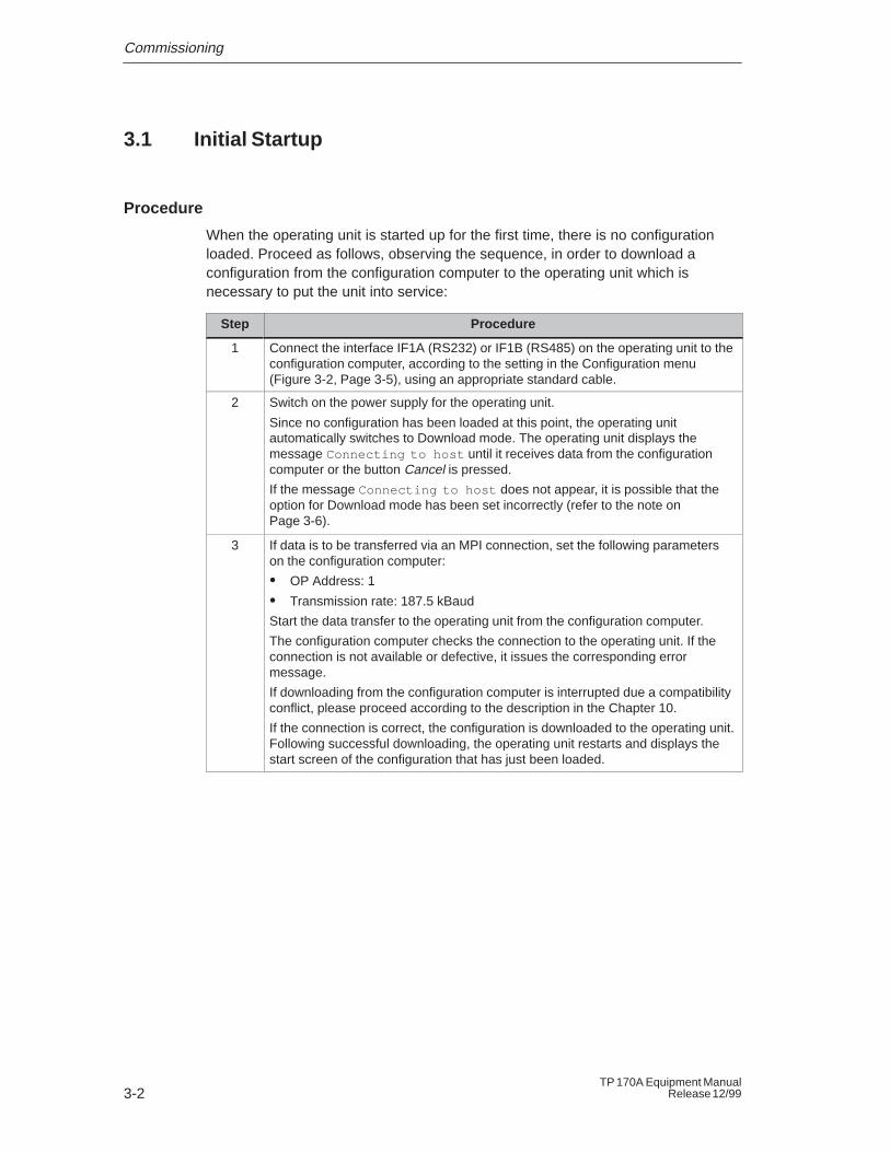
Procedure
When the operating unit is started up for the first time, there is no configurationloaded. Proceed as follows, observing the sequence, in order to download aconfiguration from the configuration computer to the operating unit which isnecessary to put the unit into service:
Step Procedure
1 Connect the interface IF1A (RS232) or IF1B (RS485) on the operating unit to theconfiguration computer, according to the setting in the Configuration menu(Figure 3-2, Page 3-5), using an appropriate standard cable.
2 Switch on the power supply for the operating unit.
Since no configuration has been loaded at this point, the operating unitautomatically switches to Download mode. The operating unit displays themessage Connecting to host until it receives data from the configurationcomputer or the button Cancel is pressed.
If the message Connecting to host does not appear, it is possible that theoption for Download mode has been set incorrectly (refer to the note onPage 3-6).
3 If data is to be transferred via an MPI connection, set the following parameterson the configuration computer:
� OP Address: 1
� Transmission rate: 187.5 kBaud
Start the data transfer to the operating unit from the configuration computer.
The configuration computer checks the connection to the operating unit. If theconnection is not available or defective, it issues the corresponding errormessage.
If downloading from the configuration computer is interrupted due a compatibilityconflict, please proceed according to the description in the Chapter 10.
If the connection is correct, the configuration is downloaded to the operating unit.Following successful downloading, the operating unit restarts and displays thestart screen of the configuration that has just been loaded.
Commissioning
3-3TP 170A Equipment ManualRelease 12/99
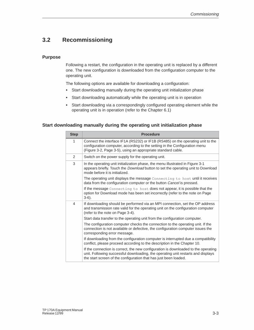
3.2 Recommissioning
Purpose
Following a restart, the configuration in the operating unit is replaced by a differentone. The new configuration is downloaded from the configuration computer to theoperating unit.
The following options are available for downloading a configuration:
� Start downloading manually during the operating unit initialization phase
� Start downloading automatically while the operating unit is in operation
� Start downloading via a correspondingly configured operating element while theoperating unit is in operation (refer to the Chapter 6.1)
Start downloading manually during the operating unit initialization phase
Step Procedure
1 Connect the interface IF1A (RS232) or IF1B (RS485) on the operating unit to theconfiguration computer, according to the setting in the Configuration menu(Figure 3-2, Page 3-5), using an appropriate standard cable.
2 Switch on the power supply for the operating unit.
3 In the operating unit initialization phase, the menu illustrated in Figure 3-1appears briefly. Touch the Download button to set the operating unit to Downloadmode before it is initialized.
The operating unit displays the message Connecting to host until it receivesdata from the configuration computer or the button Cancel is pressed.
If the message Connecting to host does not appear, it is possible that theoption for Download mode has been set incorrectly (refer to the note on Page3-6).
4 If downloading should be performed via an MPI connection, set the OP addressand transmission rate valid for the operating unit on the configuration computer(refer to the note on Page 3-4).
Start data transfer to the operating unit from the configuration computer.
The configuration computer checks the connection to the operating unit. If theconnection is not available or defective, the configuration computer issues thecorresponding error message.
If downloading from the configuration computer is interrupted due a compatibilityconflict, please proceed according to the description in the Chapter 10.
If the connection is correct, the new configuration is downloaded to the operatingunit. Following successful downloading, the operating unit restarts and displaysthe start screen of the configuration that has just been loaded.
Commissioning
3-4TP 170A Equipment Manual
Release 12/99
Start downloading automatically when the operating unit is in operation
The operating unit can be switched automatically to Download mode from normaloperation as soon as downloading is started on the connected configurationcomputer. This option is especially recommended for the test phase of a newconfiguration because the transfer is performed without intervention in theoperating unit. A condition for this is that the following settings are defined in theConfiguration menu (Figure 3-2):
MPI connection:
� Option MPI Transfer Enable activated
� Option MPI Transfer Remote activated
Serial connection:
� Option Serial Transfer Enable activated
� Option Serial Transfer Remote activated
A detailed description of the possible settings in the Configuration menu isprovided on Page 3-5.
Note: The bus parameters (e.g. MPI address, baud rate, etc.) are read out of theconfiguration which has been loaded on the operating unit. Important: A newproject with new parameters must initially be loaded on the operating unit with theold settings (on the configuration computer) because the old parameters applyhere.
Commissioning
3-5TP 170A Equipment ManualRelease 12/99
3.3 Download Mode Options
Purpose
The following options can be set for Download mode:
� The operating unit can be switched from normal operation to Download modeautomatically as soon as downloading is started on the connected configurationcomputer.
� Download mode can be restricted to a specific connection type so thatdownloading is only performed via a serial or an MPI connection.
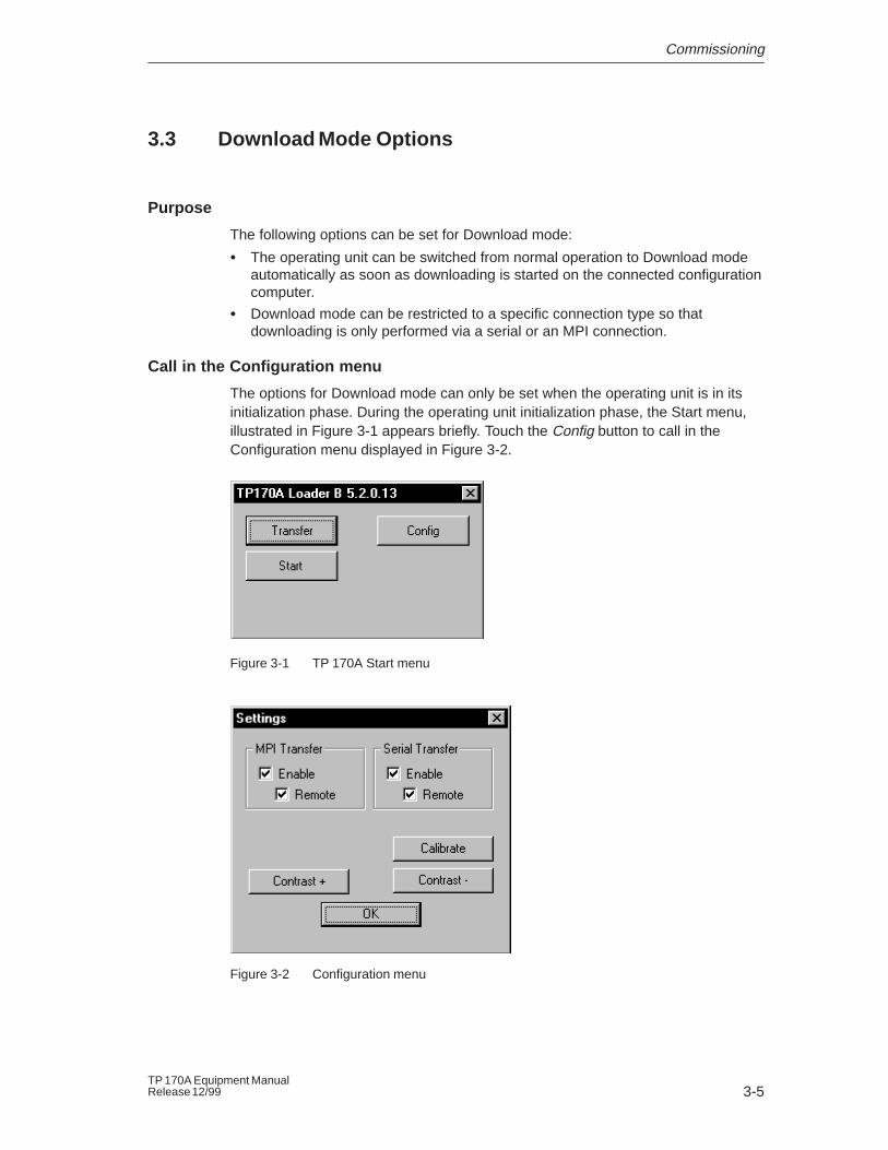
Call in the Configuration menu
The options for Download mode can only be set when the operating unit is in itsinitialization phase. During the operating unit initialization phase, the Start menu,illustrated in Figure 3-1 appears briefly. Touch the Config button to call in theConfiguration menu displayed in Figure 3-2.
Figure 3-1 TP 170A Start menu
Figure 3-2 Configuration menu
Commissioning
3-6TP 170A Equipment Manual
Release 12/99
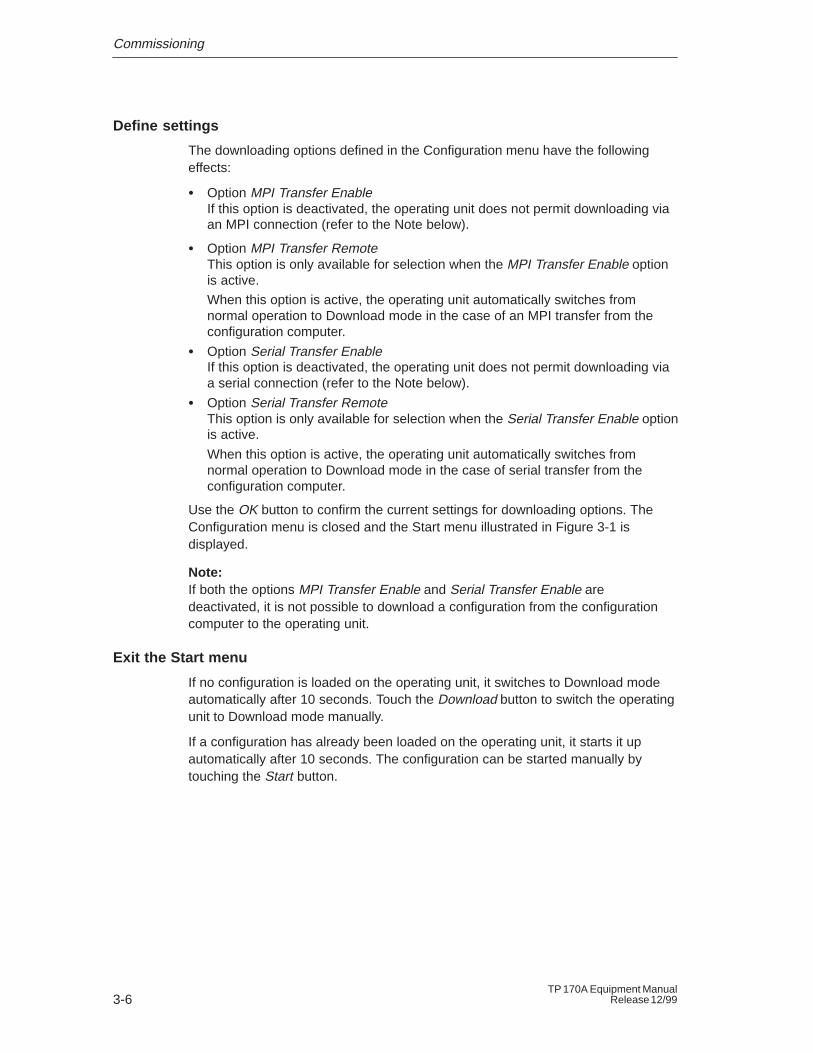
Define settings
The downloading options defined in the Configuration menu have the followingeffects:
� Option MPI Transfer EnableIf this option is deactivated, the operating unit does not permit downloading viaan MPI connection (refer to the Note below).
� Option MPI Transfer RemoteThis option is only available for selection when the MPI Transfer Enable optionis active.
When this option is active, the operating unit automatically switches fromnormal operation to Download mode in the case of an MPI transfer from theconfiguration computer.
� Option Serial Transfer EnableIf this option is deactivated, the operating unit does not permit downloading viaa serial connection (refer to the Note below).
� Option Serial Transfer RemoteThis option is only available for selection when the Serial Transfer Enable optionis active.
When this option is active, the operating unit automatically switches fromnormal operation to Download mode in the case of serial transfer from theconfiguration computer.
Use the OK button to confirm the current settings for downloading options. TheConfiguration menu is closed and the Start menu illustrated in Figure 3-1 isdisplayed.
Note: If both the options MPI Transfer Enable and Serial Transfer Enable aredeactivated, it is not possible to download a configuration from the configurationcomputer to the operating unit.
Exit the Start menu
If no configuration is loaded on the operating unit, it switches to Download modeautomatically after 10 seconds. Touch the Download button to switch the operatingunit to Download mode manually.
If a configuration has already been loaded on the operating unit, it starts it upautomatically after 10 seconds. The configuration can be started manually bytouching the Start button.
Commissioning
3-7TP 170A Equipment ManualRelease 12/99
3.4 Test Configuration
Simulation on a configuration computer
A simulator is supplied with the configuration software which can be used to testyour configuration without the necessity of a connection to a PLC. A condition forthis is that the runtime software is installed on the same configuration computer onwhich the configuration software is loaded. The runtime software is contained onthe configuration software installation CD.
The simulator is an individual application. It simulates the configuration offline, i.e.without the necessity of a physical connection to a PLC. The PLC is simulated bythe software.
Start the simulator by clicking on the symbol depicted on the left or by usingthe menu command File → Test → Start simulator.
Detailed information on operating the simulator is provided in the ProToolConfiguring Windows-based Systems user’s guide and in the configurationsoftware online help.
Note:For the test phase of a configuration, it is recommended to initiate Download modefrom normal operation automatically. Further information is available on Page 3-4.
Test with connected PLC
When a PLC is connected, it is possible to test the communication between theoperating unit and PLC. This test also determines whether the correct data areashave been configured.
Check the following configuration elements, for example:
� messages,
� screen selection,
� input field.

Commissioning
3-8TP 170A Equipment Manual
Release 12/99
4-1TP 170A Equipment ManualRelease 12/99
Operating the TP 170A
In this chapter
This chapter contains information on how to:
� operate touch elements (from Page 4-2)
� enter values (from Page 4-4)
� operate screens (Page 4-6)
Information regarding operation for special screen objects is provided in Chapter 5.
4
Operating the TP 170A
4-2TP 170A Equipment Manual
Release 12/99
4.1 Operating Touch Elements
Operating concept
The screen is used to observe the operating status of the machine or system beingmonitored and, at the same time, to intervene directly in the process runningsimply by touching the buttons and input fields displayed.
Definition
Touch elements are contact–sensitive operating elements provided on the touchpanel screen, such as buttons and input fields. Their operation is basically nodifferent from pressing conventional keys. Touch elements are operated bytouching them lightly with your finger or a suitable object.
Note
Never use pointed or sharp instruments to operate the Touch Panel to preventdamage to the plastic surface of the touch screen.
!Caution
Never touch more than one touch panel screen element at a time. If you do, anunintended action may be initiated.
Operating the TP 170A
4-3TP 170A Equipment ManualRelease 12/99
Operation acknowledgement
As soon as the touch panel detects valid contact with a touch element, it respondsby displaying a visual acknowledgement. An acknowledgment is independent ofcommunication with the PLC. It is not an indication of the required action actuallyhaving been executed.
The type of visual acknowledgement is dependent on the operating elementtouched:
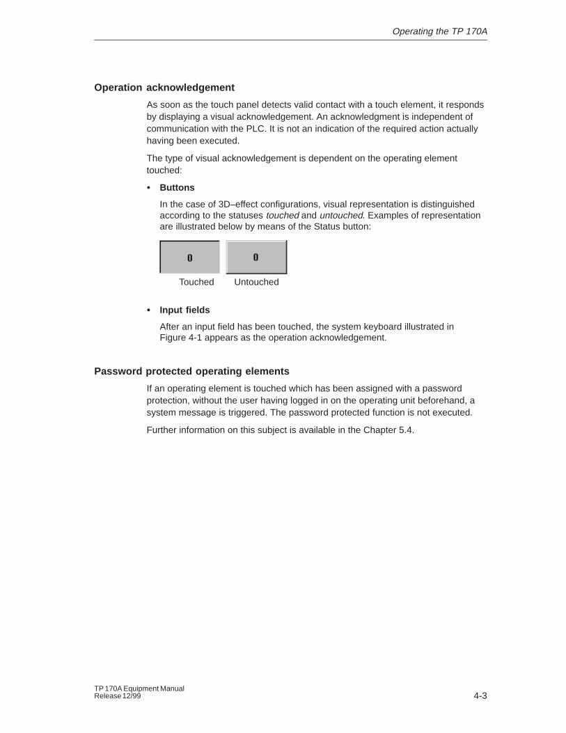
� Buttons
In the case of 3D–effect configurations, visual representation is distinguishedaccording to the statuses touched and untouched. Examples of representationare illustrated below by means of the Status button:
UntouchedTouched
� Input fields
After an input field has been touched, the system keyboard illustrated inFigure 4-1 appears as the operation acknowledgement.
Password protected operating elements
If an operating element is touched which has been assigned with a passwordprotection, without the user having logged in on the operating unit beforehand, asystem message is triggered. The password protected function is not executed.
Further information on this subject is available in the Chapter 5.4.
Operating the TP 170A
4-4TP 170A Equipment Manual
Release 12/99
4.2 Entering Values
Principles of operation
Input fields are used to enter digits and texts (characters 0 to 9 and A to F). To doso, touch the corresponding field. The system keyboard appears.
After an entry has been made correctly, the system keyboard automaticallydisappears and the entered value is accepted in the input field.
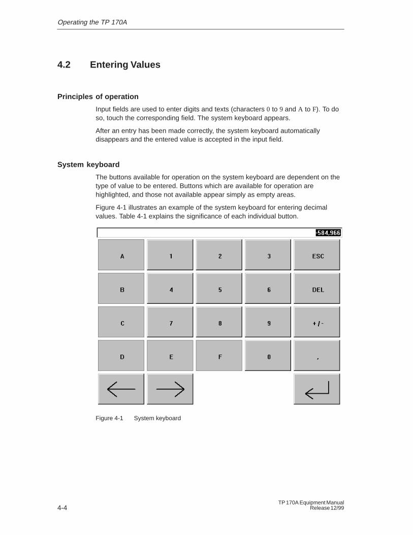
System keyboard
The buttons available for operation on the system keyboard are dependent on thetype of value to be entered. Buttons which are available for operation arehighlighted, and those not available appear simply as empty areas.
Figure 4-1 illustrates an example of the system keyboard for entering decimalvalues. Table 4-1 explains the significance of each individual button.
Figure 4-1 System keyboard
Operating the TP 170A
4-5TP 170A Equipment ManualRelease 12/99
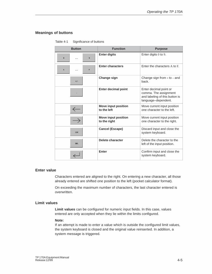
Meanings of buttons
Table 4-1 Significance of buttons
Button Function Purpose
...Enter digits Enter digits 0 to 9.
...Enter characters Enter the characters A to F.
Change sign Change sign from + to – andback.
Enter decimal point Enter decimal point orcomma. The assignmentand labeling of this button islanguage–dependent.
Move input positionto the left
Move current input positionone character to the left.
Move input positionto the right
Move current input positionone character to the right.
Cancel (Escape) Discard input and close thesystem keyboard.
Delete character Delete the character to theleft of the input position.
Enter Confirm input and close thesystem keyboard.
Enter value
Characters entered are aligned to the right. On entering a new character, all thosealready entered are shifted one position to the left (pocket calculator format).
On exceeding the maximum number of characters, the last character entered isoverwritten.
Limit values
Limit values can be configured for numeric input fields. In this case, valuesentered are only accepted when they lie within the limits configured.
Note:If an attempt is made to enter a value which is outside the configured limit values,the system keyboard is closed and the original value reinserted. In addition, asystem message is triggered.
Operating the TP 170A
4-6TP 170A Equipment Manual
Release 12/99
4.3 Operating Screens
What is a screen?
Screens visualize the progress of processes and display specified process values.A screen contains logically related process data which the operating unit can bothdisplay and modify by operating the individual values.
Screen partitions
A screen is basically composed of static and dynamic sections. The terms “static”and “dynamic” do not refer to the possibility of dynamically positioning screenpartitions but to the connection to the PLC.
Static partitions, e.g. text and graphics, are not updated by the PLC. Dynamicpartitions, e.g. input and output fields and bars, can be linked to the PLC anddisplay current values constantly read in from the PLC memory. Their connectionto the PLC is established by means of tags.
Screen objects
Various screen elements are used to display and operate a screen:
� Output fields
� Input fields
� Texts
� Graphics
� Status buttons
� Bar graphs
� Message view
A summary of all the screen objects which a TP 170A project may contain isprovided in Chapter 5.
5-1TP 170A Equipment ManualRelease 12/99
Operation of Screen Objects
In this chapter
This chapter introduces the screen objects which may be contained in aconfiguration and explains their operation. It provides the following information:
� a summary of screen objects (Page 5-2)
� the Status button (from Page 5-3)
� messages (from Page 5-5)
� logging in and out of the operating unit (Page 5-7)
5
Operation of Screen Objects
5-2TP 170A Equipment Manual
Release 12/99
5.1 Overview of Screen Objects
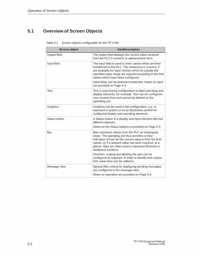
Table 5-1 Screen objects configurable for the TP 170A
Screen object Use/Description
Output field The output field displays the current value receivedfrom the PLC in numeric or alphanumeric form.
Input field The input field is used to enter values which are thentransferred to the PLC. The characters 0..9 and A..Fare available for input. Entries which lie outside thespecified value range are rejected according to the limitvalues which have been configured.
Input fields can be password protected. Notes on inputare provided on Page 4-4.
Text Text is used during configuration to label operating anddisplay elements, for example. Text can be configuredover several lines and cannot be altered on theoperating unit.
Graphics Graphics can be used in the configuration, e.g. torepresent a system or as an illustrative symbol forconfigured display and operating elements.
Status button A Status button is a display and input element with twodifferent statuses.
Notes on the Status buttons is provided on Page 5-3.
Bar Bars represent values from the PLC as rectangularareas. The operating unit thus provides a clearindication of how far the current value is from the limitvalues, or if a setpoint value has been reached, at aglance. Bars are often used to represent fill levels orworkpiece numbers.
Direction, scaling and labeling the axis can beconfigured as required. In order to identify limit values,limit value lines can be called in.
Message view Special filter criteria for displaying pending messagesare configured in the message view.
Notes on operation are provided on Page 5-6.
Operation of Screen Objects
5-3TP 170A Equipment ManualRelease 12/99
5.2 Status Button
Purpose
The Status button is an operating and display element with the two states ON andOFF. Status buttons indicate the status of a device which cannot be determinedfrom the operating unit (e.g. a motor). At the same time, it is also possible tochange the status of the device concerned on the operating unit.
Configurable properties
The behavior of the Status button can be configured:
� Option switch:
The Status button reacts as a toggle switch. Each time it is operated, itswitches to the other status and remains in that status until the button ispressed again.
In addition to the tags, which represent the current switch status, theconfiguration software can be used to define text or graphics for the twostatuses ON and OFF.
� Option push button:
The Status button reacts as a key-in button. When pressed, the Status buttonchanges to the status ON. It remains in this status as long as the Status buttonis pressed. When released, it automatically switches back to OFF.
Event-related initiation
Use the configuration software to assign the Status button one or more functionsand to define which events result in the respective function being triggered. Theevents which can be configured are:
� Changed This function is triggered as soon as the status of the Status button changes.
� OnButtonDown This function is triggered as soon as the Status button changes to the statusON.
� OnButtonUp This function is triggered as soon as the Status button changes to the statusOFF.
If the status of the Status button changes from the type switch due to amodification of the configured variables, none of the described events is triggered.
Operation of Screen Objects
5-4TP 170A Equipment Manual
Release 12/99
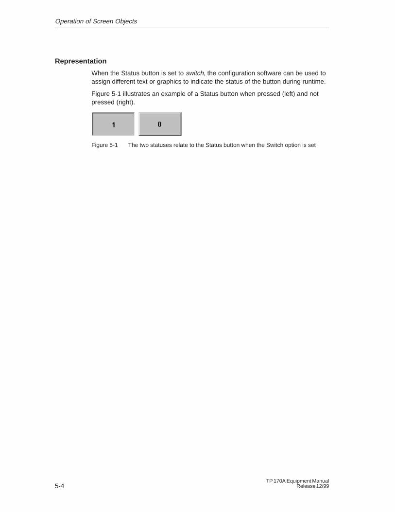
Representation
When the Status button is set to switch, the configuration software can be used toassign different text or graphics to indicate the status of the button during runtime.
Figure 5-1 illustrates an example of a Status button when pressed (left) and notpressed (right).
Figure 5-1 The two statuses relate to the Status button when the Switch option is set
Operation of Screen Objects
5-5TP 170A Equipment ManualRelease 12/99
5.3 Messages
What are messages?
Messages which appear on the operating unit indicate events and statuses relatedto the control process and operating unit itself. A message can contain text andtags.
The operating unit differentiates between event messages and system messages:
� Event messagesindicate the status in a process, e.g. Motor ON .Event messages are configured. They are triggered when a bit is set in thePLC.
� System Messagesare triggered by the operating unit. They do not have to be configured.System messages indicate incorrect operations or communication faults, forexample. A time period can be considered for system messages in theconfiguration software. This defines how long a system message appears onthe operating unit.
A list of the most important system messages is provided in the Appendix C.
Message events
These messages are triggered according to events. Message events on theTP 170A include:
� Message arrivalA message which has been triggered is considered as having arrived. As soonas message is triggered, it is displayed in the operating unit message displayand is then considered as queued.
� Message departureA message is considered as having departed when its configured time periodhas expired or the event causing the message is no longer present. As soon asa message has departed, it is deleted from the message display.
Operation of Screen Objects
5-6TP 170A Equipment Manual
Release 12/99
Message view
The TP 170A can display up to 16 messages in the message view. If more than 16messages are present simultaneously on the operating unit, the oldest message inthe queue is deleted.
It is possible to define specific views of the messages to be displayed in themessage view. Various filter criteria is available for this in the configurationsoftware.
The following can be configured
� Message categories (event and system messages only)
� Number of columns
� Number of lines per message
� Sorting (oldest or latest message at the top)
� Maximum number of visible messages
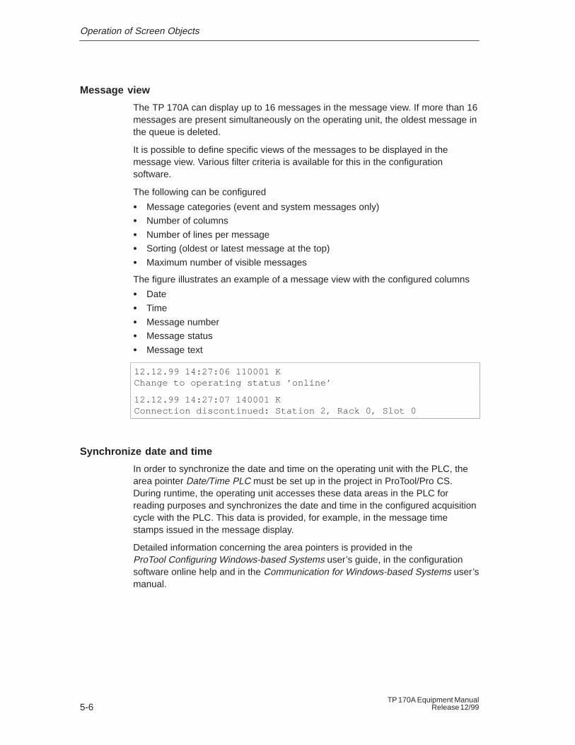
The figure illustrates an example of a message view with the configured columns
� Date
� Time
� Message number
� Message status
� Message text
12.12.99 14:27:06 110001 K Change to operating status ’online’
12.12.99 14:27:07 140001 K Connection discontinued: Station 2, Rack 0, Slot 0
Synchronize date and time
In order to synchronize the date and time on the operating unit with the PLC, thearea pointer Date/Time PLC must be set up in the project in ProTool/Pro CS.During runtime, the operating unit accesses these data areas in the PLC forreading purposes and synchronizes the date and time in the configured acquisitioncycle with the PLC. This data is provided, for example, in the message timestamps issued in the message display.
Detailed information concerning the area pointers is provided in theProTool Configuring Windows-based Systems user’s guide, in the configurationsoftware online help and in the Communication for Windows-based Systems user’smanual.
Operation of Screen Objects
5-7TP 170A Equipment ManualRelease 12/99
5.4 Logging On and Off from the Operating Unit
Purpose
During the configuration, input fields and buttons can be protected againstunauthorized operation by assigning passwords. Important parameters andsettings can then only be modified by authorized personnel. The password isdefined at the moment the element is configured and cannot be modified via theoperating unit.
Logon
If operating elements are to be assigned password protection in the configuration,it must be possible for the operator to log on. In this case, the function Logon_Usermust be linked with an operating element, preferably an input field, in theconfiguration.
In order to access a password protected operating element during runtime, it isnecessary to log on on the operating unit. It is then possible to access all passwordprotected operating elements up to the point of logging off from the operating unit.
Logoff
In order to rule out operation by unauthorized personnel, the logon should notremain active on the operating unit for too long a period of time. The followingoptions are available with which to log off from the operating unit:
� Configured logoff time expiresIf the operating unit is not operated by the user within the configured period(logoff time), he is automatically logged off from the operating unit.
� Log off of the operating unit If the configuration links the function Logoff_User with an operating element,the element can be used log off from the operating unit.

Operation of Screen Objects
5-8TP 170A Equipment Manual
Release 12/99
6-1TP 170A Equipment ManualRelease 12/99
System Settings
In this chapter
This chapter provides information on the following general settings which can bemodified on the operating unit online:
� Operating mode (Page 6-2)
� Screen contrast and calibration (Page 6-3)
6
System Settings
6-2TP 170A Equipment Manual
Release 12/99
6.1 Setting an Operating Mode
Conditions for changing operating modes
In order to switch between the operating modes described below, the functionChange_mode must be linked to an operating element in the project.
Operating modes
It is possible to switch between various operating modes on the operating unit:
Offline modeIn this mode there is no logical connection between the operating unit and PLC.The operating unit can be operated, but processes cannot be operated orvisualized.
Online modeWhen using this mode, processes can be operated and visualized withoutrestriction. There is a logical connection between the operating unit and PLC or theoperating unit attempts to establish one.Online mode is the predefined operating mode each time the operating unit isstarted up.
Download modeThis operating mode is used to transfer a configuration from the configurationcomputer to the operating unit. Further information on Download mode is providedin Chapter 3.3.
System Settings
6-3TP 170A Equipment ManualRelease 12/99
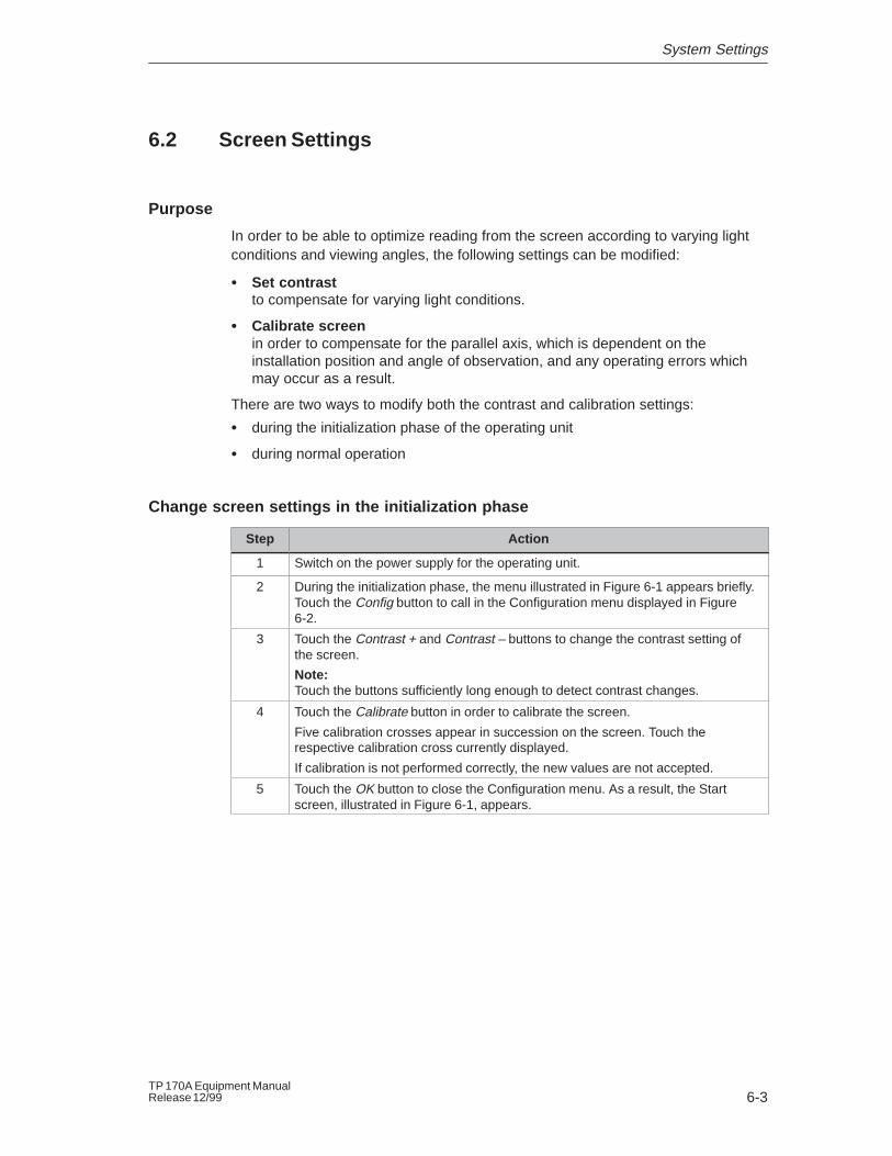
6.2 Screen Settings
Purpose
In order to be able to optimize reading from the screen according to varying lightconditions and viewing angles, the following settings can be modified:
� Set contrastto compensate for varying light conditions.
� Calibrate screenin order to compensate for the parallel axis, which is dependent on theinstallation position and angle of observation, and any operating errors whichmay occur as a result.
There are two ways to modify both the contrast and calibration settings:
� during the initialization phase of the operating unit
� during normal operation
Change screen settings in the initialization phase
Step Action
1 Switch on the power supply for the operating unit.
2 During the initialization phase, the menu illustrated in Figure 6-1 appears briefly.Touch the Config button to call in the Configuration menu displayed in Figure6-2.
3 Touch the Contrast + and Contrast – buttons to change the contrast setting ofthe screen.
Note: Touch the buttons sufficiently long enough to detect contrast changes.
4 Touch the Calibrate button in order to calibrate the screen.
Five calibration crosses appear in succession on the screen. Touch therespective calibration cross currently displayed.
If calibration is not performed correctly, the new values are not accepted.
5 Touch the OK button to close the Configuration menu. As a result, the Startscreen, illustrated in Figure 6-1, appears.
System Settings
6-4TP 170A Equipment Manual
Release 12/99
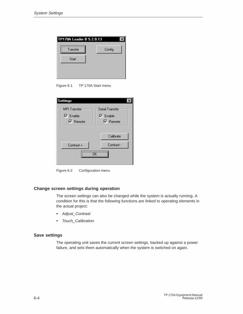
Figure 6-1 TP 170A Start menu
Figure 6-2 Configuration menu
Change screen settings during operation
The screen settings can also be changed while the system is actually running. Acondition for this is that the following functions are linked to operating elements inthe actual project:
� Adjust_Contrast
� Touch_Calibration
Save settings
The operating unit saves the current screen settings, backed up against a powerfailure, and sets them automatically when the system is switched on again.
7-1TP 170A Equipment ManualRelease 12/99
Installation
In this chapter
This chapter provides information on:
� the installation of the operating unit (from Page 7-2)
� electrical connections to
– the power supply (Page 7-6)
– the configuration computer (Page 7-7)
– the PLC (Page 7-8)
7
Installation
7-2TP 170A Equipment Manual
Release 12/99
7.1 Mechanical Installation
Installation location and conditions
The operating unit is designed for installation in the front panels of cabinets andconsoles. Cut a mounting cut-out in the front panel in preparation for installation ofthe unit. The thickness of the front panel must not exceed 6 mm. No other holesneed to be drilled for mounting.
Details regarding the mounting depth and mounting cut-out are provided onPage 8-2.
Degree of protection
The IP65 degree of protection for the front panel can only be ensured when theseal on the front plate of the operating unit is fitted correctly.
!Caution
� The unit must be brought to room temperature before it is commissioned. Ifcondensation forms, do not switch the unit on until it absolutely dry.
� To prevent the operating unit overheating during operation,
– the angle of inclination from vertical installation may not exceed a maximumof �35�.
– do not expose the operating unit to direct sunlight.
– ensure that the ventilation slits in the housing remain free after installation.
� When the cabinet is opened, certain parts of the system that may conducthazardous voltage are exposed.
� The unit was function-tested before shipping. If a fault occurs nevertheless,please enclose a full account of the fault when returning the unit.
Installation
7-3TP 170A Equipment ManualRelease 12/99
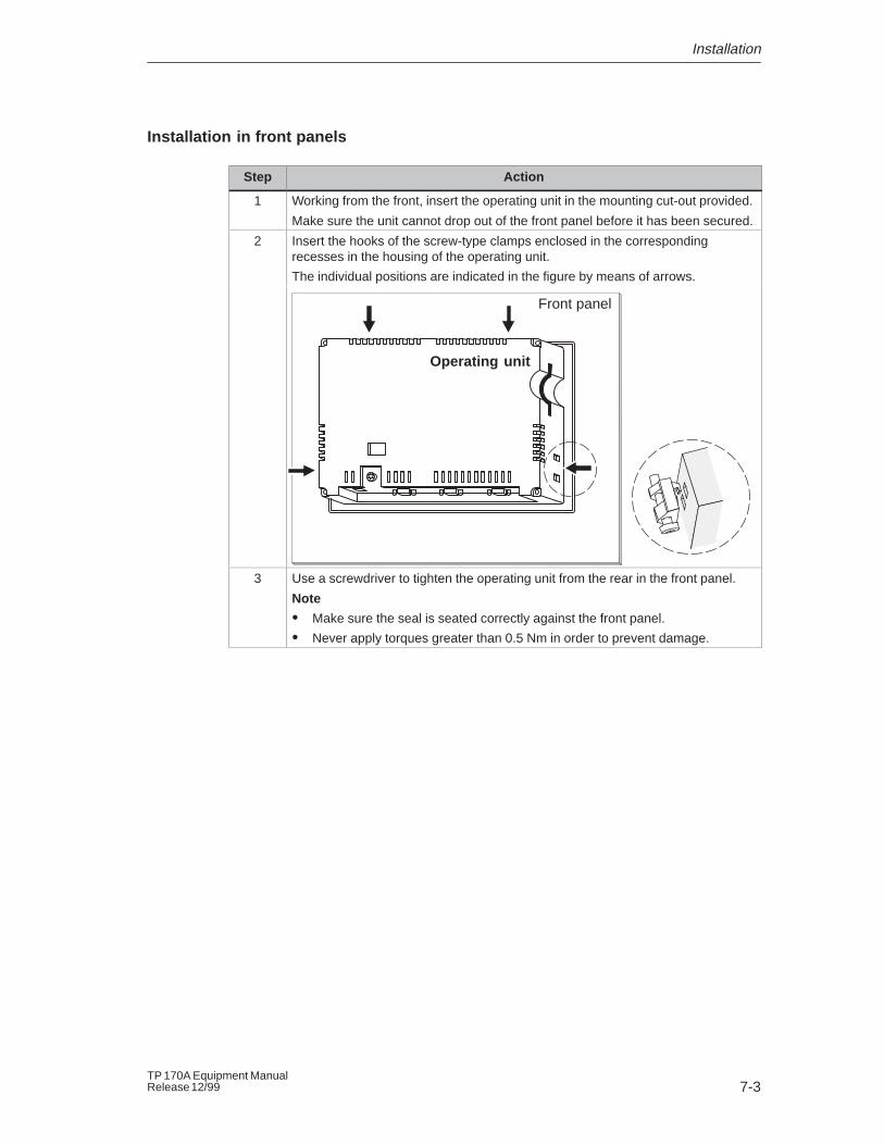
Installation in front panels
Step Action
1 Working from the front, insert the operating unit in the mounting cut-out provided.
Make sure the unit cannot drop out of the front panel before it has been secured.
2 Insert the hooks of the screw-type clamps enclosed in the correspondingrecesses in the housing of the operating unit.
The individual positions are indicated in the figure by means of arrows.
Front panel
Operating unit
3 Use a screwdriver to tighten the operating unit from the rear in the front panel.
Note
� Make sure the seal is seated correctly against the front panel.
� Never apply torques greater than 0.5 Nm in order to prevent damage.
Installation
7-4TP 170A Equipment Manual
Release 12/99
7.2 Electrical Installation
Electrical connections
The operating unit requires electrical connections
� to the power supply,
� to the configuration computer (PU or PC),
� to the PLC.
The electrical connection to the configuration computer is required purely fordownloading project data.
EMC compatible installation
A precondition for error-free operation is an EMC compatible hardware design ofthe PLC and the use of interference-proof cables. The guidelines oninterference-free design of the PLCs apply equally to installation of the operatingunit.
!Caution
� Only shielded cables are permitted for all signal connections.
� Screw or lock all plug connections.
� Do not install signal lines in the same cable ducts as power cables.
� Siemens AG refuses to accept liability for malfunctions and damage arisingfrom use of self-made cables or cables from other manufacturers.
Installation
7-5TP 170A Equipment ManualRelease 12/99
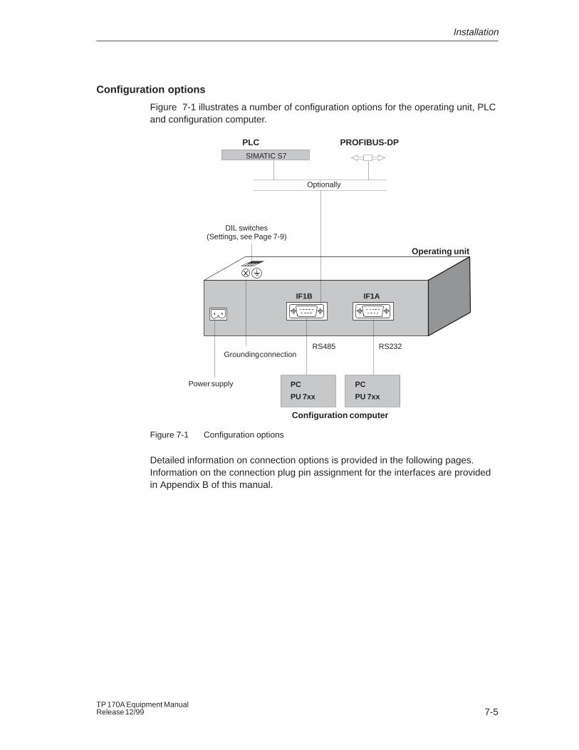
Configuration options
Figure 7-1 illustrates a number of configuration options for the operating unit, PLCand configuration computer.
IF1B IF1A
Operating unit
Power supply
Optionally
PLC PROFIBUS-DP
SIMATIC S7
PC
PU 7xx
DIL switches(Settings, see Page 7-9)
Grounding connection
PC
PU 7xx
Configuration computer
RS485 RS232
Figure 7-1 Configuration options
Detailed information on connection options is provided in the following pages.Information on the connection plug pin assignment for the interfaces are providedin Appendix B of this manual.
Installation
7-6TP 170A Equipment Manual
Release 12/99
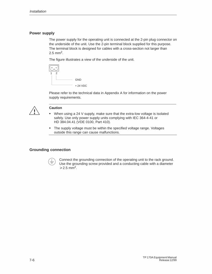
Power supply
The power supply for the operating unit is connected at the 2-pin plug connector onthe underside of the unit. Use the 2-pin terminal block supplied for this purpose.The terminal block is designed for cables with a cross-section not larger than2.5 mm2.
The figure illustrates a view of the underside of the unit.
GND
+ 24 VDC
1 2
Please refer to the technical data in Appendix A for information on the powersupply requirements.
!Caution
� When using a 24 V supply, make sure that the extra-low voltage is isolatedsafely. Use only power supply units complying with IEC 364-4-41 orHD 384.04.41 (VDE 0100, Part 410).
� The supply voltage must be within the specified voltage range. Voltagesoutside this range can cause malfunctions.
Grounding connection
Connect the grounding connection of the operating unit to the rack ground.Use the grounding screw provided and a conducting cable with a diameter�2.5 mm2.
Installation
7-7TP 170A Equipment ManualRelease 12/99
7.2.1 Connect Configuration Computer
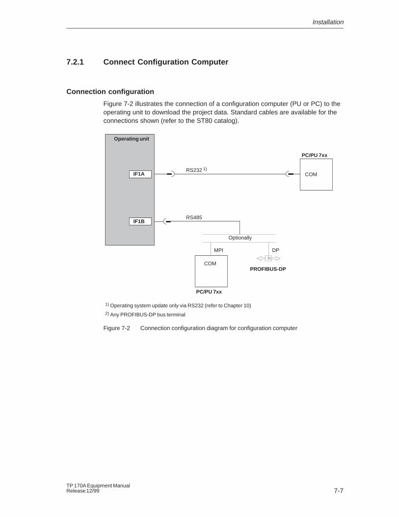
Connection configuration
Figure 7-2 illustrates the connection of a configuration computer (PU or PC) to theoperating unit to download the project data. Standard cables are available for theconnections shown (refer to the ST80 catalog).
COMIF1A
PC/PU 7xx
Operating unit
RS232 1)
IF1B
Optionally
PROFIBUS-DP
MPI
COM
PC/PU 7xx
DP
1) Operating system update only via RS232 (refer to Chapter 10)2) Any PROFIBUS-DP bus terminal
RS485
2)
Figure 7-2 Connection configuration diagram for configuration computer
Installation
7-8TP 170A Equipment Manual
Release 12/99
7.2.2 Connect PLC
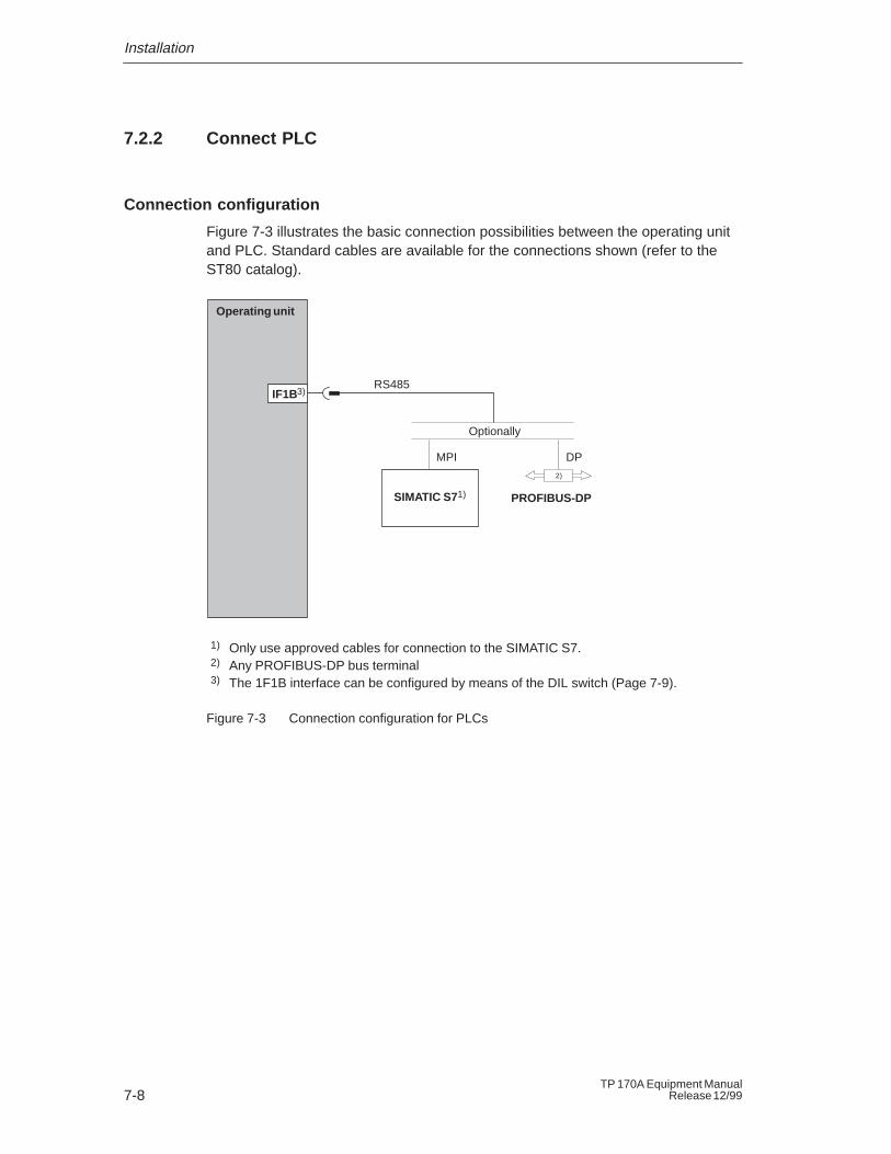
Connection configuration
Figure 7-3 illustrates the basic connection possibilities between the operating unitand PLC. Standard cables are available for the connections shown (refer to theST80 catalog).
1) Only use approved cables for connection to the SIMATIC S7.2) Any PROFIBUS-DP bus terminal3) The 1F1B interface can be configured by means of the DIL switch (Page 7-9).
2)
Operating unit
IF1B3)
Optionally
PROFIBUS-DP
MPI DP
RS485
SIMATIC S71)
Figure 7-3 Connection configuration for PLCs
Installation
7-9TP 170A Equipment ManualRelease 12/99
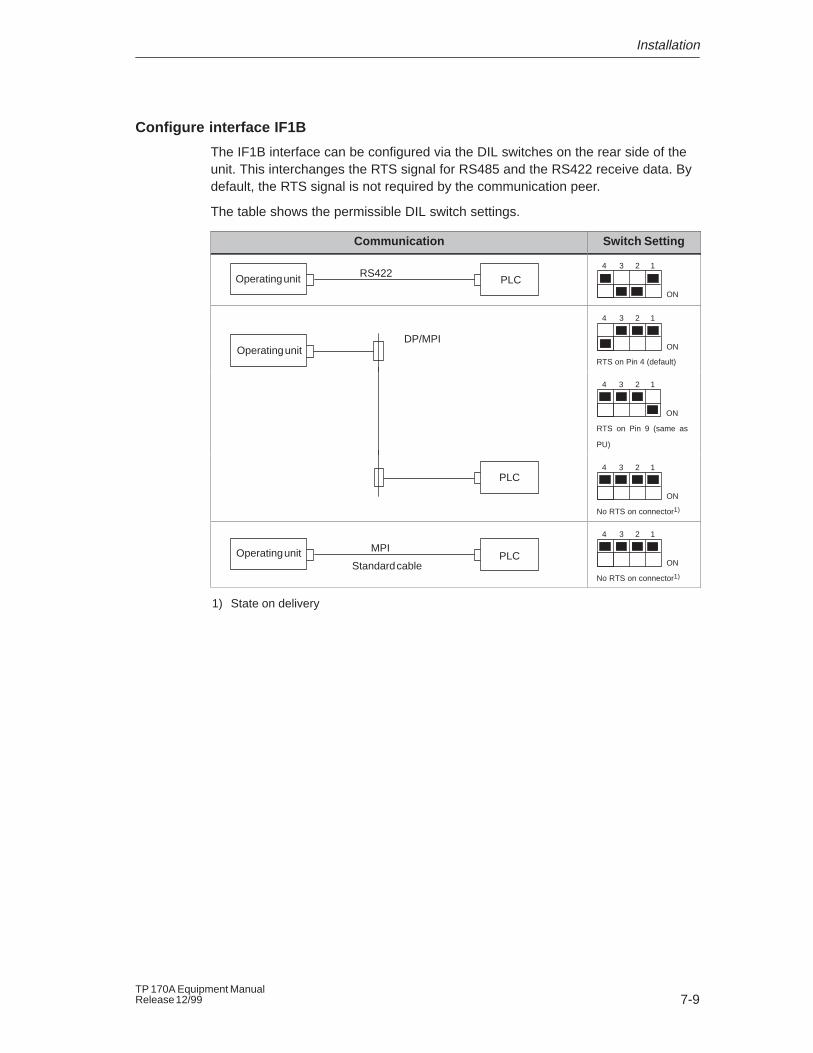
Configure interface IF1B
The IF1B interface can be configured via the DIL switches on the rear side of theunit. This interchanges the RTS signal for RS485 and the RS422 receive data. Bydefault, the RTS signal is not required by the communication peer.
The table shows the permissible DIL switch settings.
Communication Switch Setting
PLCRS422Operating unit
ON
1234
DP/MPIOperating unit ON
1234
RTS on Pin 4 (default)
RTS on Pin 9 (same as
PU)
ON
1234
PLC
No RTS on connector1)
ON
1234
PLCMPI
Standard cableOperating unit
ON
1234
No RTS on connector1)
1) State on delivery

Installation
7-10TP 170A Equipment Manual
Release 12/99
8-1TP 170A Equipment ManualRelease 12/99
Unit Description
In this chapter
This chapter provides information on:
� Dimensions (Page 8-2),
� Connection elements (Page 8-3),
� Communication options (Page 8-4).
8
Unit Description
8-2TP 170A Equipment Manual
Release 12/99
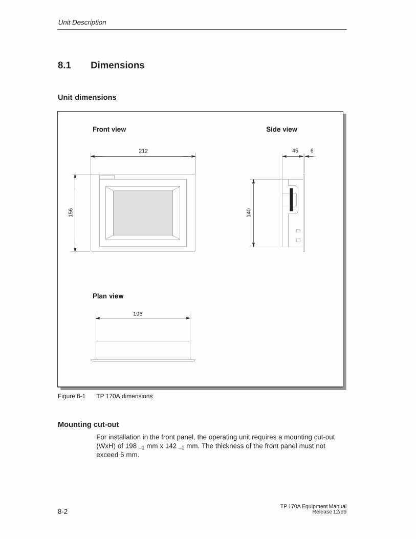
8.1 Dimensions
Unit dimensions
196
45212 6
156
����� ������� ���
���� ���
140
Figure 8-1 TP 170A dimensions
Mounting cut-out
For installation in the front panel, the operating unit requires a mounting cut-out(WxH) of 198 –1 mm x 142 –1 mm. The thickness of the front panel must notexceed 6 mm.
Unit Description
8-3TP 170A Equipment ManualRelease 12/99
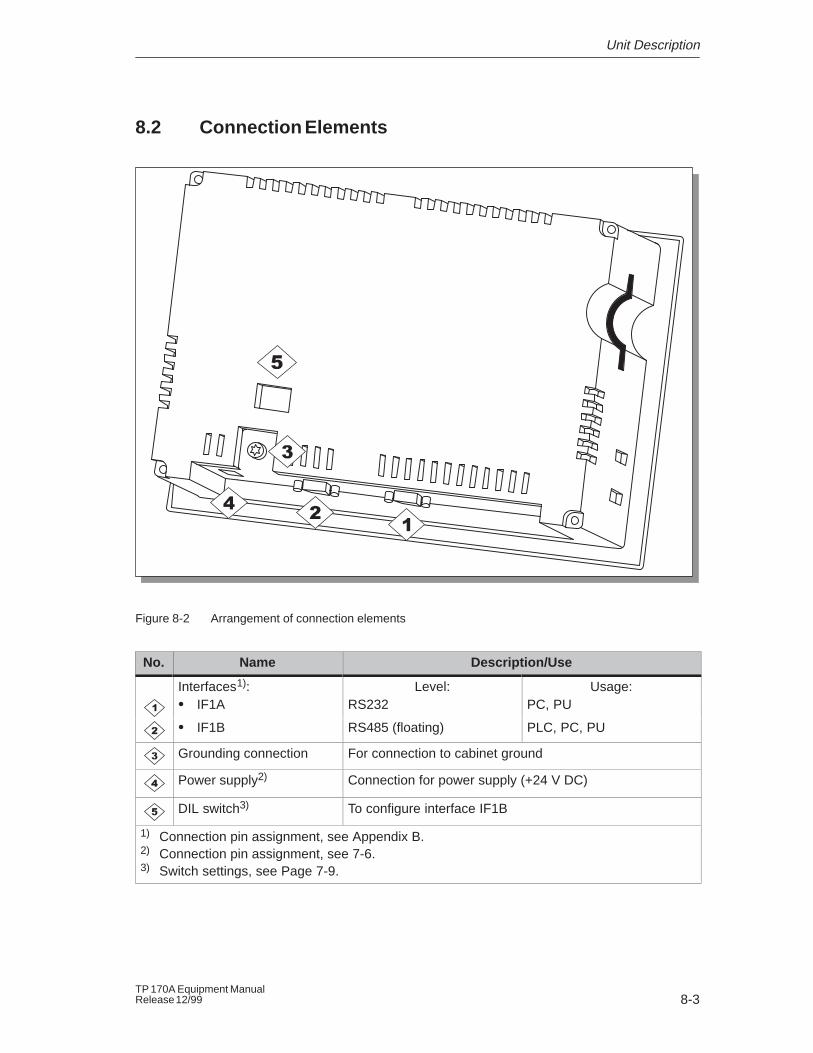
8.2 Connection Elements
Figure 8-2 Arrangement of connection elements
No. Name Description/Use
Interfaces1): Level: Usage:� IF1A RS232 PC, PU
� IF1B RS485 (floating) PLC, PC, PU
Grounding connection For connection to cabinet ground
Power supply2) Connection for power supply (+24 V DC)
DIL switch3) To configure interface IF1B
1) Connection pin assignment, see Appendix B.2) Connection pin assignment, see 7-6.3) Switch settings, see Page 7-9.
Unit Description
8-4TP 170A Equipment Manual
Release 12/99
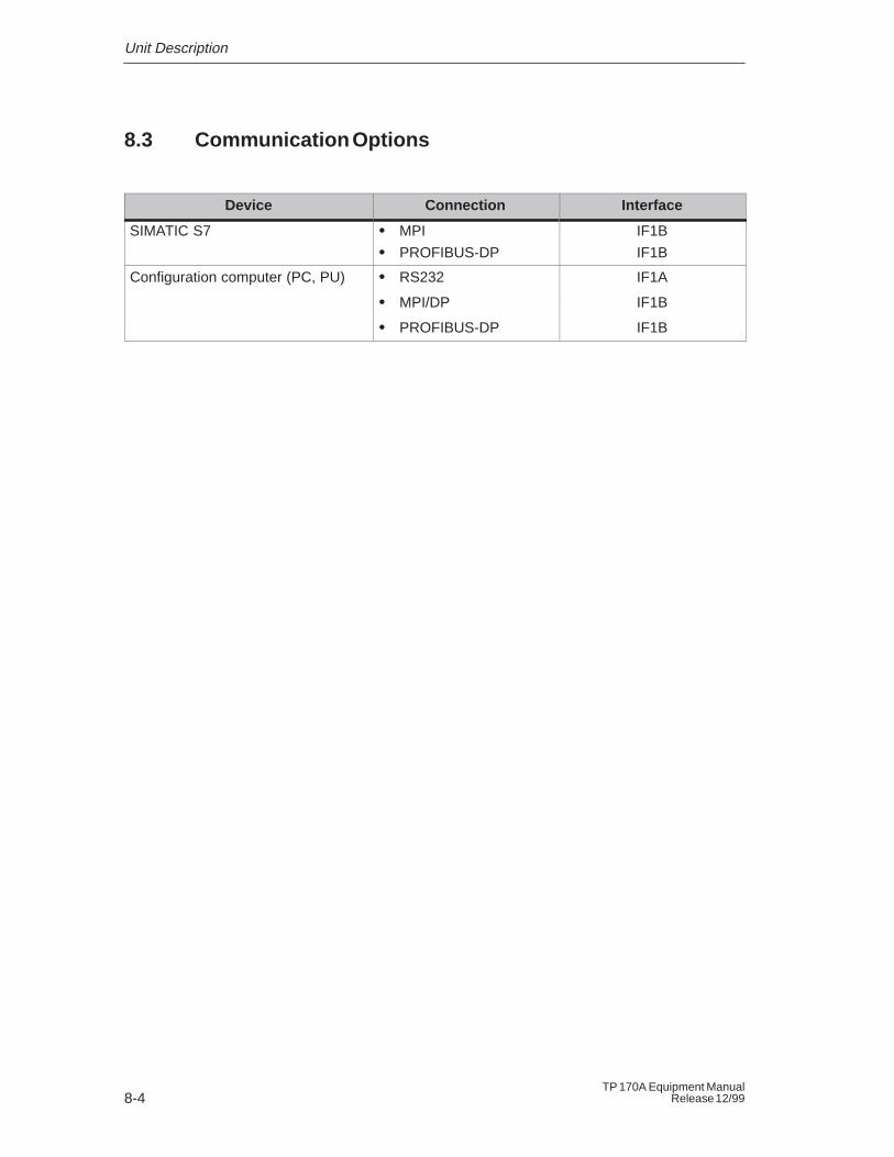
8.3 Communication Options
Device Connection Interface
SIMATIC S7 � MPI
� PROFIBUS-DP
IF1B
IF1B
Configuration computer (PC, PU) � RS232 IF1A
� MPI/DP IF1B
� PROFIBUS-DP IF1B
9-1TP 170A Equipment ManualRelease 12/99
Maintenance/Upkeep
Cleaning the screen
Clean the operating unit screen at regular intervals using a damp cloth. Do notclean the unit while it is turned on. This ensures that functions are not triggered byinadvertently coming into contact with the touch screen.
Only use water and washing up liquid or screen cleaning foam to dampen cloths.Never spray the cleaning agent directly onto the screen, but onto the cleaningcloth. Never use aggressive solvents or scouring powder.
Protective foil
A protective foil is available for the operating unit (refer to the ST80 catalog). Thefoil prevents the screen being scratched and soiled.
9

Maintenance/Upkeep
9-2TP 170A Equipment Manual
Release 12/99
10-1TP 170A Equipment ManualRelease 12/99
Operating System Update
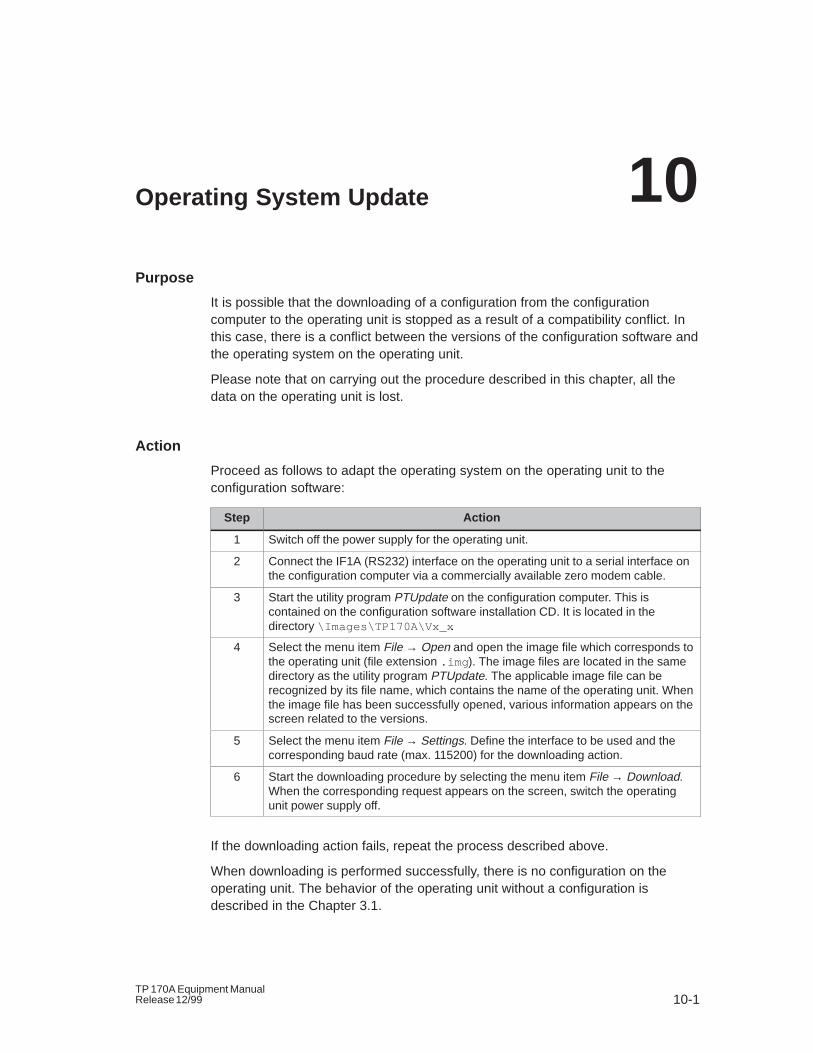
Purpose
It is possible that the downloading of a configuration from the configurationcomputer to the operating unit is stopped as a result of a compatibility conflict. Inthis case, there is a conflict between the versions of the configuration software andthe operating system on the operating unit.
Please note that on carrying out the procedure described in this chapter, all thedata on the operating unit is lost.
Action
Proceed as follows to adapt the operating system on the operating unit to theconfiguration software:
Step Action
1 Switch off the power supply for the operating unit.
2 Connect the IF1A (RS232) interface on the operating unit to a serial interface onthe configuration computer via a commercially available zero modem cable.
3 Start the utility program PTUpdate on the configuration computer. This iscontained on the configuration software installation CD. It is located in thedirectory \Images\TP170A\Vx_x .
4 Select the menu item File → Open and open the image file which corresponds tothe operating unit (file extension .img ). The image files are located in the samedirectory as the utility program PTUpdate. The applicable image file can berecognized by its file name, which contains the name of the operating unit. Whenthe image file has been successfully opened, various information appears on thescreen related to the versions.
5 Select the menu item File → Settings. Define the interface to be used and thecorresponding baud rate (max. 115200) for the downloading action.
6 Start the downloading procedure by selecting the menu item File → Download.When the corresponding request appears on the screen, switch the operatingunit power supply off.
If the downloading action fails, repeat the process described above.
When downloading is performed successfully, there is no configuration on theoperating unit. The behavior of the operating unit without a configuration isdescribed in the Chapter 3.1.
10

Operating System Update
10-2TP 170A Equipment Manual
Release 12/99
APPENDICES
A Technical Data
B Interface Assignments
C System Messages
D ESD Guidelines
E SIMATIC HMI Documentation

APPENDICES
J-2TP 170A Equipment Manual
Release 12/99
A-1TP 170A Equipment ManualRelease 12/99
Technical Data
In this Appendix
This section of the Appendix contains technical data on the TP 170A concerning:
� Housing
� Processor
� Memory
� Software
� Display
� Power supply
� Ambient conditions
� Noise immunity / Noise transmission
� Approvals
A
Technical Data
A-2TP 170A Equipment Manual
Release 12/99
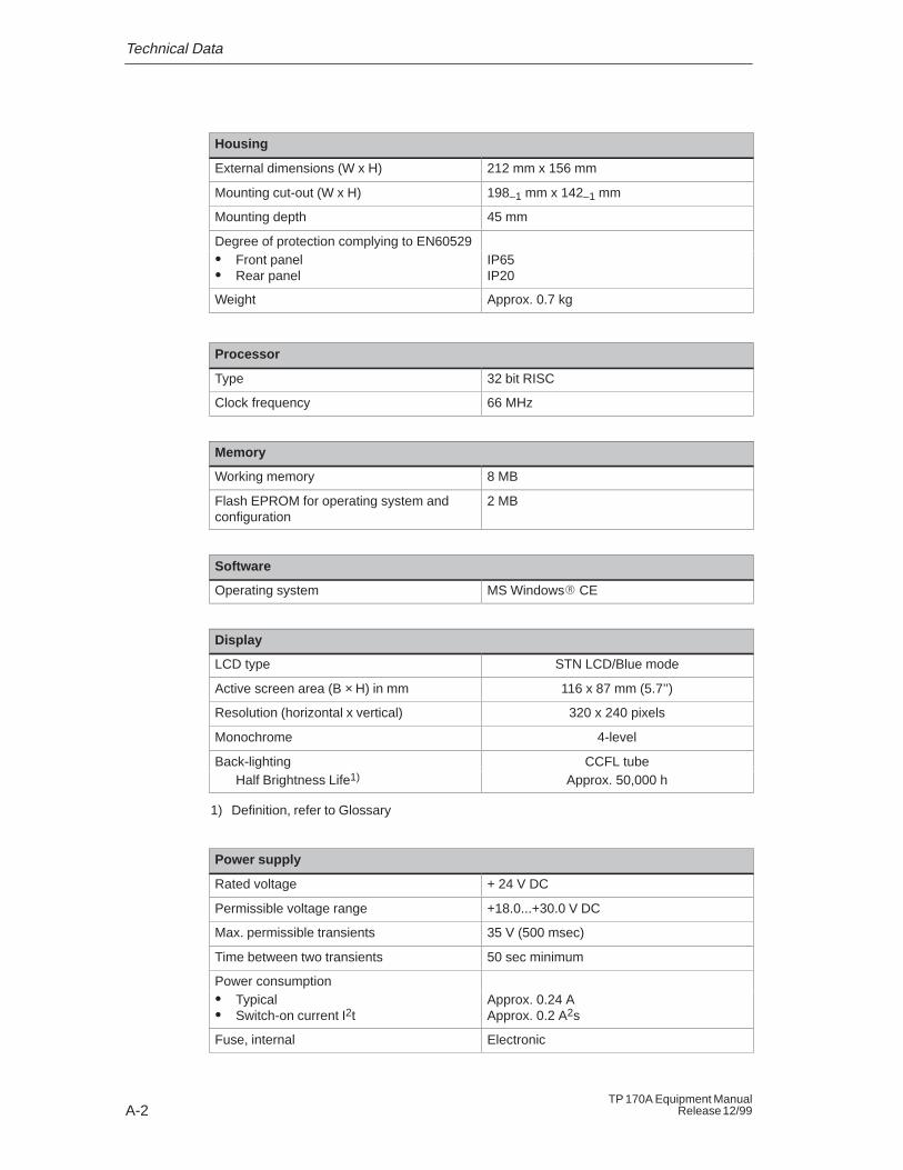
Housing
External dimensions (W x H) 212 mm x 156 mm
Mounting cut-out (W x H) 198–1 mm x 142–1 mm
Mounting depth 45 mm
Degree of protection complying to EN60529� Front panel� Rear panel
IP65IP20
Weight Approx. 0.7 kg
Processor
Type 32 bit RISC
Clock frequency 66 MHz
Memory
Working memory 8 MB
Flash EPROM for operating system and configuration
2 MB
Software
Operating system MS Windows� CE
Display
LCD type STN LCD/Blue mode
Active screen area (B × H) in mm 116 x 87 mm (5.7’’)
Resolution (horizontal x vertical) 320 x 240 pixels
Monochrome 4-level
Back-lighting CCFL tubeHalf Brightness Life1) Approx. 50,000 h
1) Definition, refer to Glossary
Power supply
Rated voltage + 24 V DC
Permissible voltage range +18.0...+30.0 V DC
Max. permissible transients 35 V (500 msec)
Time between two transients 50 sec minimum
Power consumption� Typical� Switch-on current I2t
Approx. 0.24 AApprox. 0.2 A2s
Fuse, internal Electronic
Technical Data
A-3TP 170A Equipment ManualRelease 12/99
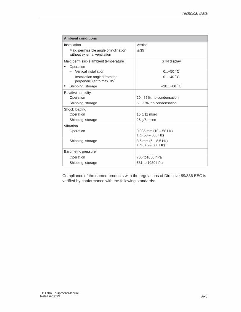
Ambient conditions
Installation
Max. permissible angle of inclinationwithout external ventilation
Vertical
�35�
Max. permissible ambient temperature
� Operation
STN display
– Vertical installation
– Installation angled from theperpendicular to max. 35�
0...+50 ��
0...+40 �C
� Shipping, storage –20...+60 ��
Relative humidityOperation
Shipping, storage
20...85%, no condensation
5...90%, no condensation
Shock loadingOperation
Shipping, storage
15 g/11 msec
25 g/6 msec
VibrationOperation 0.035 mm (10 – 58 Hz)
1 g (58 – 500 Hz)
Shipping, storage 3.5 mm (5 – 8,5 Hz)1 g (8.5 – 500 Hz)
Barometric pressure
Operation
Shipping, storage
706 to1030 hPa
581 to 1030 hPa
Compliance of the named products with the regulations of Directive 89/336 EEC isverified by conformance with the following standards:
Technical Data
A-4TP 170A Equipment Manual
Release 12/99
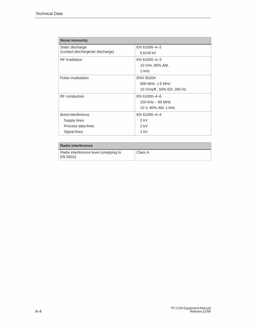
Noise immunity
Static discharge (contact discharge/air discharge)
EN 61000–4–2
6 kV/8 kV
RF irradiation EN 61000–4–3
10 V/m, 80% AM,
1 kHz
Pulse modulation ENV 50204
900 MHz �5 MHz
10 V/meff., 50% ED, 200 Hz
RF conduction EN 61000–4–6
150 kHz – 80 MHz
10 V, 80% AM, 1 kHz
Burst interference
Supply lines
Process data lines
Signal lines
EN 61000–4–4
2 kV
2 kV
1 kV
Radio interference
Radio interference level complying to EN 55011
Class A
Technical Data
A-5TP 170A Equipment ManualRelease 12/99
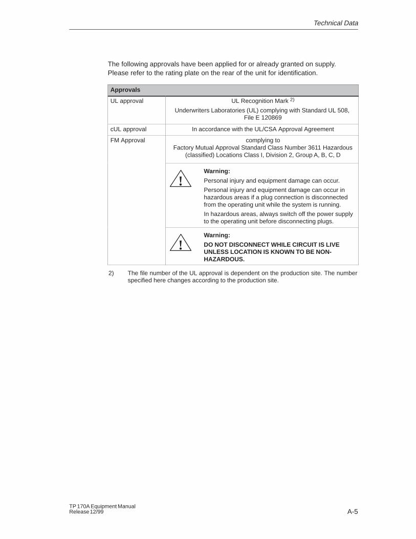
The following approvals have been applied for or already granted on supply.Please refer to the rating plate on the rear of the unit for identification.
Approvals
UL approval UL Recognition Mark 2)
Underwriters Laboratories (UL) complying with Standard UL 508, File E 120869
cUL approval In accordance with the UL/CSA Approval Agreement
FM Approval complying toFactory Mutual Approval Standard Class Number 3611 Hazardous
(classified) Locations Class I, Division 2, Group A, B, C, D
Warning:
Personal injury and equipment damage can occur.
Personal injury and equipment damage can occur inhazardous areas if a plug connection is disconnectedfrom the operating unit while the system is running.
In hazardous areas, always switch off the power supplyto the operating unit before disconnecting plugs.
!
Warning:
DO NOT DISCONNECT WHILE CIRCUIT IS LIVEUNLESS LOCATION IS KNOWN TO BE NON-HAZARDOUS.
!
2) The file number of the UL approval is dependent on the production site. The numberspecified here changes according to the production site.

Technical Data
A-6TP 170A Equipment Manual
Release 12/99
B-1TP 170A Equipment ManualRelease 12/99
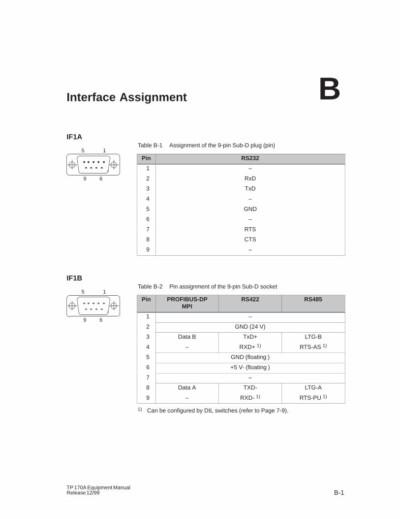
Interface Assignment
IF1ATable B-1 Assignment of the 9-pin Sub-D plug (pin)
Pin RS232
1 –
2 RxD
3 TxD
4 –
5 GND
6 –
7 RTS
8 CTS
9 –
IF1BTable B-2 Pin assignment of the 9-pin Sub-D socket
Pin PROFIBUS-DPMPI
RS422 RS485
1 –
2 GND (24 V)
3 Data B TxD+ LTG-B
4 – RXD+ 1) RTS-AS 1)
5 GND (floating )
6 +5 V- (floating )
7 –
8 Data A TXD- LTG-A
9 – RXD- 1) RTS-PU 1)
1) Can be configured by DIL switches (refer to Page 7-9).
B
5 1
9 6
5 1
9 6

Interface Assignment
B-2TP 170A Equipment Manual
Release 12/99
C-1TP 170A Equipment ManualRelease 12/99
System Messages
In this chapter
This chapter contains a selection of important system messages forWindows-based systems. The table indicates when the messages occur and howthey, or their cause, can be cleared. Not every message is relevant for eachoperating unit.
Message number
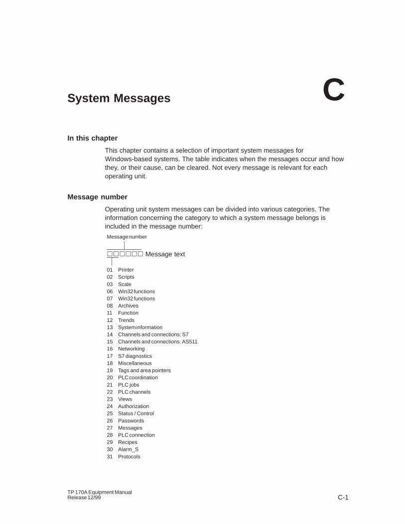
Operating unit system messages can be divided into various categories. Theinformation concerning the category to which a system message belongs isincluded in the message number:
������ Message text
Message number
01 Printer02 Scripts03 Scale06 Win32 functions07 Win32 functions08 Archives11 Function12 Trends13 System information14 Channels and connections: S715 Channels and connections: AS51116 Networking17 S7 diagnostics18 Miscellaneous19 Tags and area pointers20 PLC coordination21 PLC jobs22 PLC channels23 Views24 Authorization25 Status / Control26 Passwords27 Messages28 PLC connection29 Recipes30 Alarm_S31 Protocols
C
System Messages
C-2TP 170A Equipment Manual
Release 12/99
The message category enables the identification of a general area in which thecause of the fault is to be found.
Note
System messages are issued in the language currently set on the operating unit.
System message parameters
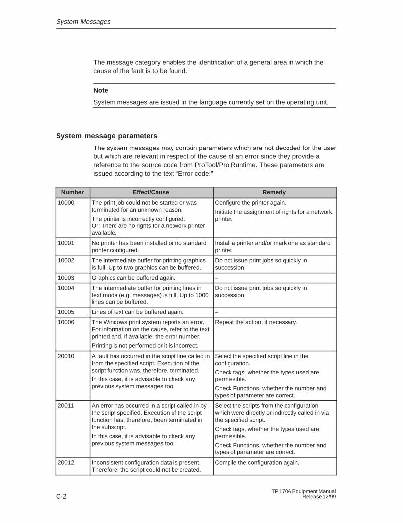
The system messages may contain parameters which are not decoded for the userbut which are relevant in respect of the cause of an error since they provide areference to the source code from ProTool/Pro Runtime. These parameters areissued according to the text “Error code:”
Number Effect/Cause Remedy
10000 The print job could not be started or wasterminated for an unknown reason.
The printer is incorrectly configured.Or: There are no rights for a network printeravailable.
Configure the printer again.
Initiate the assignment of rights for a networkprinter.
10001 No printer has been installed or no standardprinter configured.
Install a printer and/or mark one as standardprinter.
10002 The intermediate buffer for printing graphicsis full. Up to two graphics can be buffered.
Do not issue print jobs so quickly insuccession.
10003 Graphics can be buffered again. –
10004 The intermediate buffer for printing lines intext mode (e.g. messages) is full. Up to 1000lines can be buffered.
Do not issue print jobs so quickly insuccession.
10005 Lines of text can be buffered again. –
10006 The Windows print system reports an error.For information on the cause, refer to the textprinted and, if available, the error number.
Printing is not performed or it is incorrect.
Repeat the action, if necessary.
20010 A fault has occurred in the script line called infrom the specified script. Execution of thescript function was, therefore, terminated.
In this case, it is advisable to check anyprevious system messages too.
Select the specified script line in theconfiguration.
Check tags, whether the types used arepermissible.
Check Functions, whether the number andtypes of parameter are correct.
20011 An error has occurred in a script called in bythe script specified. Execution of the scriptfunction has, therefore, been terminated inthe subscript.
In this case, it is advisable to check anyprevious system messages too.
Select the scripts from the configurationwhich were directly or indirectly called in viathe specified script.
Check tags, whether the types used arepermissible.
Check Functions, whether the number andtypes of parameter are correct.
20012 Inconsistent configuration data is present.Therefore, the script could not be created.
Compile the configuration again.
System Messages
C-3TP 170A Equipment ManualRelease 12/99
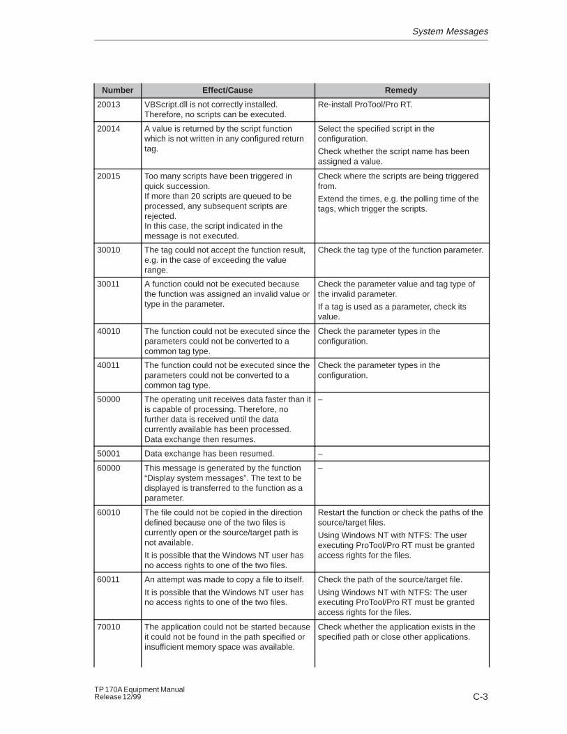
RemedyEffect/CauseNumber
20013 VBScript.dll is not correctly installed.Therefore, no scripts can be executed.
Re-install ProTool/Pro RT.
20014 A value is returned by the script functionwhich is not written in any configured returntag.
Select the specified script in theconfiguration.
Check whether the script name has beenassigned a value.
20015 Too many scripts have been triggered inquick succession.If more than 20 scripts are queued to beprocessed, any subsequent scripts arerejected.In this case, the script indicated in themessage is not executed.
Check where the scripts are being triggeredfrom.
Extend the times, e.g. the polling time of thetags, which trigger the scripts.
30010 The tag could not accept the function result,e.g. in the case of exceeding the valuerange.
Check the tag type of the function parameter.
30011 A function could not be executed becausethe function was assigned an invalid value ortype in the parameter.
Check the parameter value and tag type ofthe invalid parameter.
If a tag is used as a parameter, check itsvalue.
40010 The function could not be executed since theparameters could not be converted to acommon tag type.
Check the parameter types in theconfiguration.
40011 The function could not be executed since theparameters could not be converted to acommon tag type.
Check the parameter types in theconfiguration.
50000 The operating unit receives data faster than itis capable of processing. Therefore, nofurther data is received until the datacurrently available has been processed.Data exchange then resumes.
–
50001 Data exchange has been resumed. –
60000 This message is generated by the function“Display system messages”. The text to bedisplayed is transferred to the function as aparameter.
–
60010 The file could not be copied in the directiondefined because one of the two files iscurrently open or the source/target path isnot available.
It is possible that the Windows NT user hasno access rights to one of the two files.
Restart the function or check the paths of thesource/target files.
Using Windows NT with NTFS: The userexecuting ProTool/Pro RT must be grantedaccess rights for the files.
60011 An attempt was made to copy a file to itself.
It is possible that the Windows NT user hasno access rights to one of the two files.
Check the path of the source/target file.
Using Windows NT with NTFS: The userexecuting ProTool/Pro RT must be grantedaccess rights for the files.
70010 The application could not be started becauseit could not be found in the path specified orinsufficient memory space was available.
Check whether the application exists in thespecified path or close other applications.
System Messages
C-4TP 170A Equipment Manual
Release 12/99
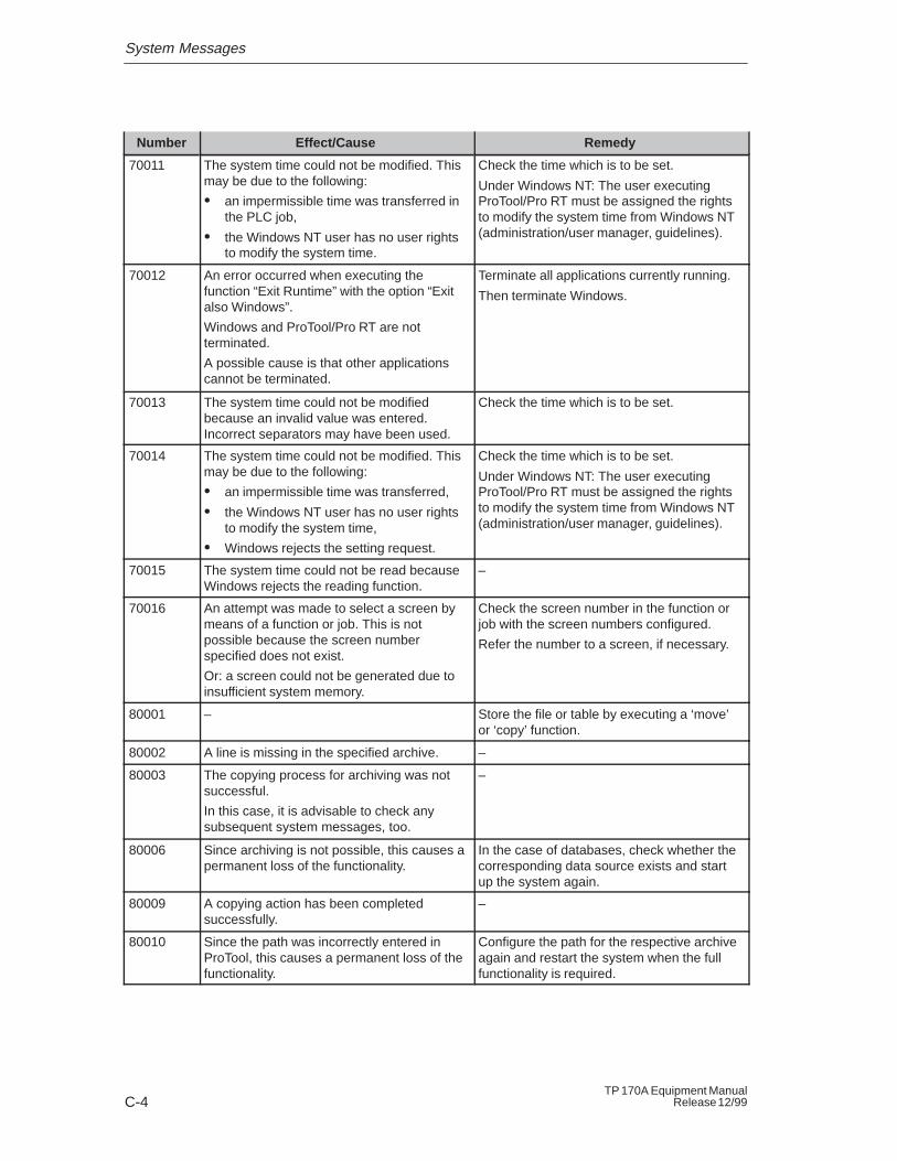
RemedyEffect/CauseNumber
70011 The system time could not be modified. Thismay be due to the following:
� an impermissible time was transferred inthe PLC job,
� the Windows NT user has no user rightsto modify the system time.
Check the time which is to be set.
Under Windows NT: The user executingProTool/Pro RT must be assigned the rightsto modify the system time from Windows NT(administration/user manager, guidelines).
70012 An error occurred when executing thefunction “Exit Runtime” with the option “Exitalso Windows”.
Windows and ProTool/Pro RT are notterminated.
A possible cause is that other applicationscannot be terminated.
Terminate all applications currently running.
Then terminate Windows.
70013 The system time could not be modifiedbecause an invalid value was entered.Incorrect separators may have been used.
Check the time which is to be set.
70014 The system time could not be modified. Thismay be due to the following:
� an impermissible time was transferred,
� the Windows NT user has no user rightsto modify the system time,
� Windows rejects the setting request.
Check the time which is to be set.
Under Windows NT: The user executingProTool/Pro RT must be assigned the rightsto modify the system time from Windows NT(administration/user manager, guidelines).
70015 The system time could not be read becauseWindows rejects the reading function.
–
70016 An attempt was made to select a screen bymeans of a function or job. This is notpossible because the screen numberspecified does not exist.
Or: a screen could not be generated due toinsufficient system memory.
Check the screen number in the function orjob with the screen numbers configured.
Refer the number to a screen, if necessary.
80001 – Store the file or table by executing a ‘move’or ‘copy’ function.
80002 A line is missing in the specified archive. –
80003 The copying process for archiving was notsuccessful.
In this case, it is advisable to check anysubsequent system messages, too.
–
80006 Since archiving is not possible, this causes apermanent loss of the functionality.
In the case of databases, check whether thecorresponding data source exists and startup the system again.
80009 A copying action has been completedsuccessfully.
–
80010 Since the path was incorrectly entered inProTool, this causes a permanent loss of thefunctionality.
Configure the path for the respective archiveagain and restart the system when the fullfunctionality is required.
System Messages
C-5TP 170A Equipment ManualRelease 12/99
RemedyEffect/CauseNumber
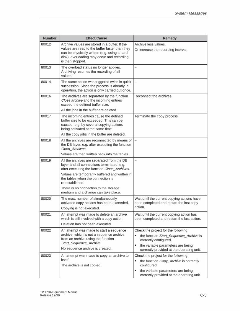
80012 Archive values are stored in a buffer. If thevalues are read to the buffer faster than theycan be physically written (e.g. using a harddisk), overloading may occur and recordingis then stopped.
Archive less values.
Or increase the recording interval.
80013 The overload status no longer applies.Archiving resumes the recording of allvalues.
–
80014 The same action was triggered twice in quicksuccession. Since the process is already inoperation, the action is only carried out once.
–
80016 The archives are separated by the functionClose archive and the incoming entriesexceed the defined buffer size.
All the jobs in the buffer are deleted.
Reconnect the archives.
80017 The incoming entries cause the definedbuffer size to be exceeded. This can becaused, e.g. by several copying actionsbeing activated at the same time.
All the copy jobs in the buffer are deleted.
Terminate the copy process.
80018 All the archives are reconnected by means ofthe DB layer, e.g. after executing the functionOpen_Archives.
Values are then written back into the tables.
–
80019 All the archives are separated from the DBlayer and all connections terminated, e.g.after executing the function Close_Archives.
Values are temporarily buffered and written inthe tables when the connection isre-established.
There is no connection to the storagemedium and a change can take place.
–
80020 The max. number of simultaneouslyactivated copy actions has been exceeded.
Copying is not executed.
Wait until the current copying actions havebeen completed and restart the last copyaction.
80021 An attempt was made to delete an archivewhich is still involved with a copy action.
Deletion has not been executed.
Wait until the current copying action hasbeen completed and restart the last action.
80022 An attempt was made to start a sequencearchive, which is not a sequence archive,from an archive using the functionStart_Sequence_Archive.
No sequence archive is created.
Check the project for the following:
� the function Start_Sequence_Archive iscorrectly configured.
� the variable parameters are beingcorrectly provided at the operating unit.
80023 An attempt was made to copy an archive toitself.
The archive is not copied.
Check the project for the following:
� the function Copy_Archive is correctlyconfigured.
� the variable parameters are beingcorrectly provided at the operating unit.
System Messages
C-6TP 170A Equipment Manual
Release 12/99
RemedyEffect/CauseNumber
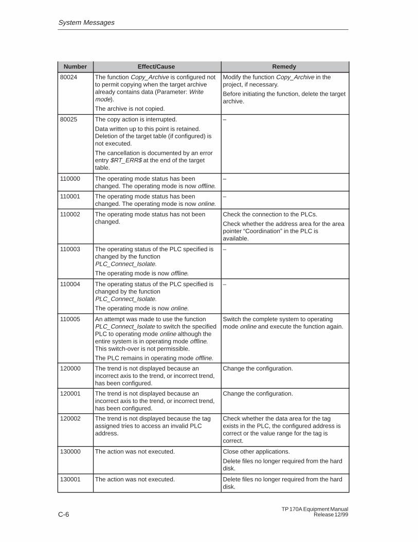
80024 The function Copy_Archive is configured notto permit copying when the target archivealready contains data (Parameter: Writemode).
The archive is not copied.
Modify the function Copy_Archive in theproject, if necessary.
Before initiating the function, delete the targetarchive.
80025 The copy action is interrupted.
Data written up to this point is retained.Deletion of the target table (if configured) isnot executed.
The cancellation is documented by an errorentry $RT_ERR$ at the end of the targettable.
–
110000 The operating mode status has beenchanged. The operating mode is now offline.
–
110001 The operating mode status has beenchanged. The operating mode is now online.
–
110002 The operating mode status has not beenchanged.
Check the connection to the PLCs.
Check whether the address area for the areapointer “Coordination” in the PLC isavailable.
110003 The operating status of the PLC specified ischanged by the functionPLC_Connect_Isolate.
The operating mode is now offline.
–
110004 The operating status of the PLC specified ischanged by the functionPLC_Connect_Isolate.
The operating mode is now online.
–
110005 An attempt was made to use the functionPLC_Connect_Isolate to switch the specifiedPLC to operating mode online although theentire system is in operating mode offline.This switch-over is not permissible.
The PLC remains in operating mode offline.
Switch the complete system to operatingmode online and execute the function again.
120000 The trend is not displayed because anincorrect axis to the trend, or incorrect trend,has been configured.
Change the configuration.
120001 The trend is not displayed because anincorrect axis to the trend, or incorrect trend,has been configured.
Change the configuration.
120002 The trend is not displayed because the tagassigned tries to access an invalid PLCaddress.
Check whether the data area for the tagexists in the PLC, the configured address iscorrect or the value range for the tag iscorrect.
130000 The action was not executed. Close other applications.
Delete files no longer required from the harddisk.
130001 The action was not executed. Delete files no longer required from the harddisk.
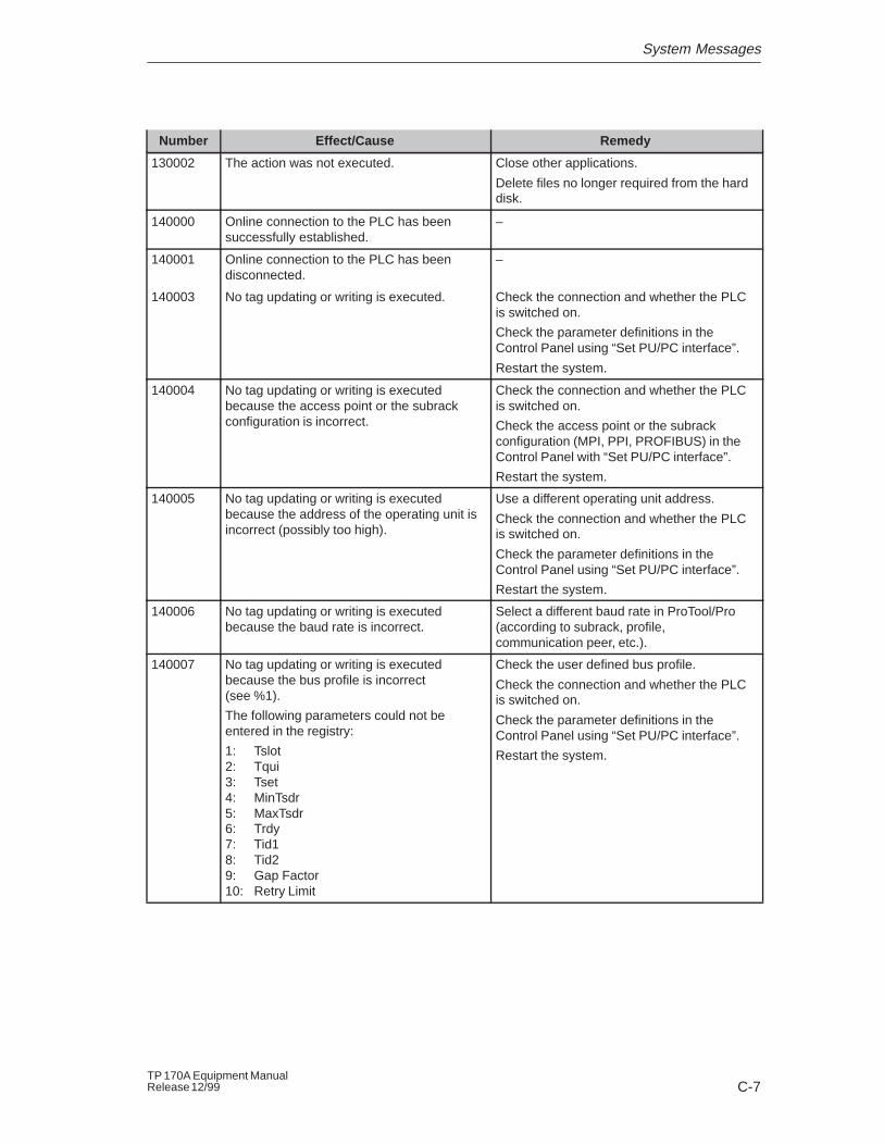
System Messages
C-7TP 170A Equipment ManualRelease 12/99
RemedyEffect/CauseNumber
130002 The action was not executed. Close other applications.
Delete files no longer required from the harddisk.
140000 Online connection to the PLC has beensuccessfully established.
–
140001 Online connection to the PLC has beendisconnected.
–
140003 No tag updating or writing is executed. Check the connection and whether the PLCis switched on.
Check the parameter definitions in theControl Panel using “Set PU/PC interface”.
Restart the system.
140004 No tag updating or writing is executedbecause the access point or the subrackconfiguration is incorrect.
Check the connection and whether the PLCis switched on.
Check the access point or the subrackconfiguration (MPI, PPI, PROFIBUS) in theControl Panel with “Set PU/PC interface”.
Restart the system.
140005 No tag updating or writing is executedbecause the address of the operating unit isincorrect (possibly too high).
Use a different operating unit address.
Check the connection and whether the PLCis switched on.
Check the parameter definitions in theControl Panel using “Set PU/PC interface”.
Restart the system.
140006 No tag updating or writing is executedbecause the baud rate is incorrect.
Select a different baud rate in ProTool/Pro(according to subrack, profile,communication peer, etc.).
140007 No tag updating or writing is executedbecause the bus profile is incorrect(see %1).
The following parameters could not beentered in the registry:
1: Tslot2: Tqui3: Tset4: MinTsdr5: MaxTsdr6: Trdy7: Tid18: Tid29: Gap Factor10: Retry Limit
Check the user defined bus profile.
Check the connection and whether the PLCis switched on.
Check the parameter definitions in theControl Panel using “Set PU/PC interface”.
Restart the system.
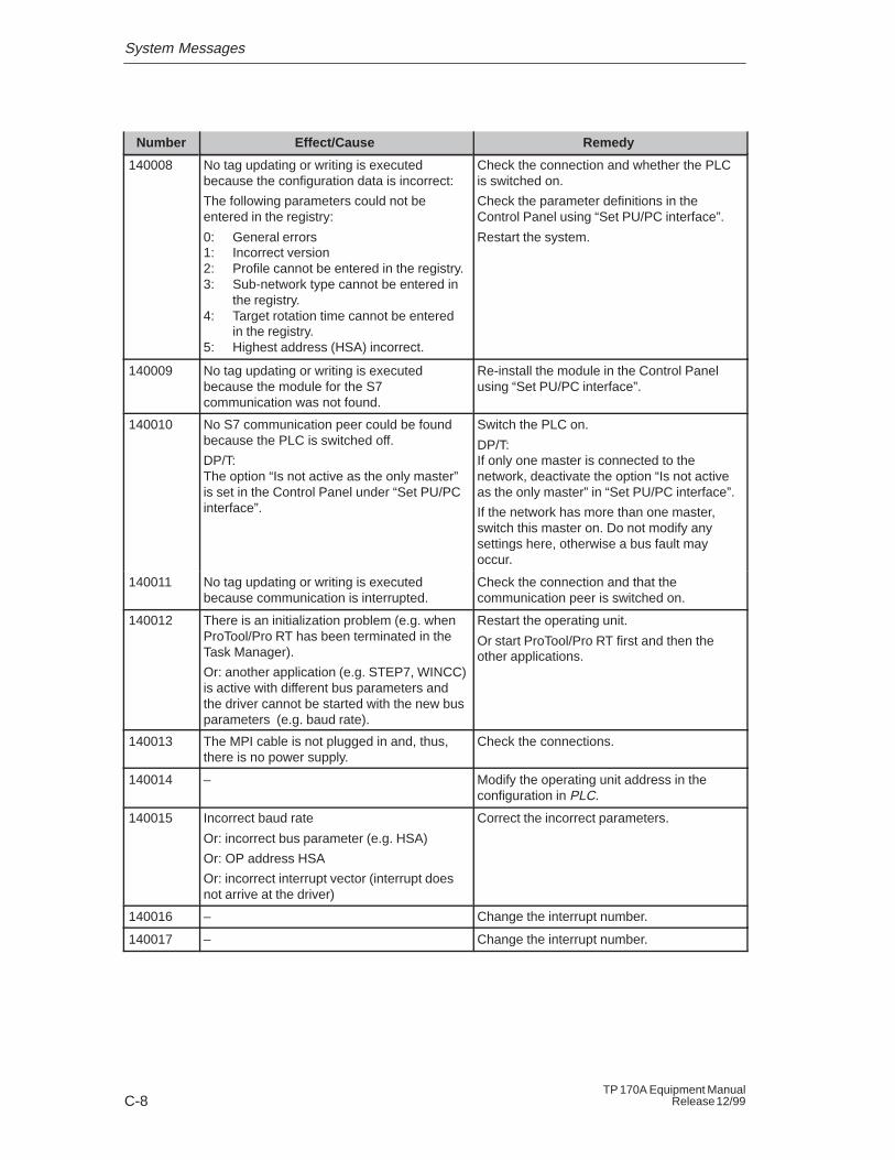
System Messages
C-8TP 170A Equipment Manual
Release 12/99
RemedyEffect/CauseNumber
140008 No tag updating or writing is executedbecause the configuration data is incorrect:
The following parameters could not beentered in the registry:
0: General errors1: Incorrect version2: Profile cannot be entered in the registry.3: Sub-network type cannot be entered in
the registry.4: Target rotation time cannot be entered
in the registry.5: Highest address (HSA) incorrect.
Check the connection and whether the PLCis switched on.
Check the parameter definitions in theControl Panel using “Set PU/PC interface”.
Restart the system.
140009 No tag updating or writing is executedbecause the module for the S7communication was not found.
Re-install the module in the Control Panelusing “Set PU/PC interface”.
140010 No S7 communication peer could be foundbecause the PLC is switched off.
DP/T:The option “Is not active as the only master”is set in the Control Panel under “Set PU/PCinterface”.
Switch the PLC on.
DP/T:If only one master is connected to thenetwork, deactivate the option “Is not activeas the only master” in “Set PU/PC interface”.
If the network has more than one master,switch this master on. Do not modify anysettings here, otherwise a bus fault mayoccur.
140011 No tag updating or writing is executedbecause communication is interrupted.
Check the connection and that thecommunication peer is switched on.
140012 There is an initialization problem (e.g. whenProTool/Pro RT has been terminated in theTask Manager).
Or: another application (e.g. STEP7, WINCC)is active with different bus parameters andthe driver cannot be started with the new busparameters (e.g. baud rate).
Restart the operating unit.
Or start ProTool/Pro RT first and then theother applications.
140013 The MPI cable is not plugged in and, thus,there is no power supply.
Check the connections.
140014 – Modify the operating unit address in theconfiguration in PLC.
140015 Incorrect baud rate
Or: incorrect bus parameter (e.g. HSA)
Or: OP address HSA
Or: incorrect interrupt vector (interrupt doesnot arrive at the driver)
Correct the incorrect parameters.
140016 – Change the interrupt number.
140017 – Change the interrupt number.
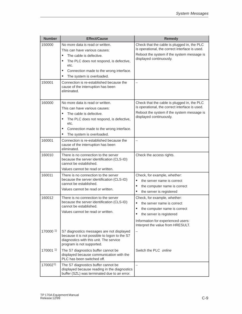
System Messages
C-9TP 170A Equipment ManualRelease 12/99
RemedyEffect/CauseNumber
150000 No more data is read or written.
This can have various causes:
� The cable is defective.
� The PLC does not respond, is defective,etc.
� Connection made to the wrong interface.
� The system is overloaded.
Check that the cable is plugged in, the PLCis operational, the correct interface is used.
Reboot the system if the system message isdisplayed continuously.
150001 Connection is re-established because thecause of the interruption has beeneliminated.
–
160000 No more data is read or written.
This can have various causes:
� The cable is defective.
� The PLC does not respond, is defective,etc.
� Connection made to the wrong interface.
� The system is overloaded.
Check that the cable is plugged in, the PLCis operational, the correct interface is used.
Reboot the system if the system message isdisplayed continuously.
160001 Connection is re-established because thecause of the interruption has beeneliminated.
–
160010 There is no connection to the serverbecause the server identification (CLS-ID)cannot be established.
Values cannot be read or written.
Check the access rights.
160011 There is no connection to the serverbecause the server identification (CLS-ID)cannot be established.
Values cannot be read or written.
Check, for example, whether:
� the server name is correct
� the computer name is correct
� the server is registered
160012 There is no connection to the serverbecause the server identification (CLS-ID)cannot be established.
Values cannot be read or written.
Check, for example, whether:
� the server name is correct
� the computer name is correct
� the server is registered
Information for experienced users:Interpret the value from HRESULT.
170000 1) S7 diagnostics messages are not displayedbecause it is not possible to logon to the S7diagnostics with this unit. The serviceprogram is not supported.
–
170001 1) The S7 diagnostics buffer cannot bedisplayed because communication with thePLC has been switched off.
Switch the PLC online
1700021) The S7 diagnostics buffer cannot bedisplayed because reading in the diagnosticsbuffer (SZL) was terminated due to an error.
–
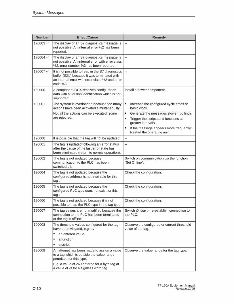
System Messages
C-10TP 170A Equipment Manual
Release 12/99
RemedyEffect/CauseNumber
170003 1) The display of an S7 diagnostics message isnot possible. An internal error %2 has beenreported.
–
170004 1) The display of an S7 diagnostics message isnot possible. An internal error with error class%2, error number %3 has been reported.
–
170007 1) It is not possible to read in the S7 diagnosticsbuffer (SZL) because it was terminated withan internal error with error class %2 and errorcode %3.
–
180000 A component/OCX receives configurationdata with a version identification which is notsupported.
Install a newer component.
180001 The system is overloaded because too manyactions have been activated simultaneously.
Not all the actions can be executed, someare rejected.
� Increase the configured cycle times orbasic clock.
� Generate the messages slower (polling).
� Trigger the scripts and functions atgreater intervals.
� If the message appears more frequently: Restart the operating unit.
190000 It is possible that the tag will not be updated. –
190001 The tag is updated following an error statusafter the cause of the last error state hasbeen eliminated (return to normal operation).
–
190002 The tag is not updated becausecommunication to the PLC has beenswitched off.
Switch on communication via the function“Set Online”.
190004 The tag is not updated because theconfigured address is not available for thistag .
Check the configuration.
190005 The tag is not updated because theconfigured PLC type does not exist for thistag .
Check the configuration.
190006 The tag is not updated because it is notpossible to map the PLC type in the tag type.
Check the configuration.
190007 The tag values are not modified because theconnection to the PLC has been terminatedor the tag is offline.
Switch Online or re-establish connection tothe PLC.
190008 The threshold values configured for the taghave been violated, e.g. by
� an entered value,
� a function,
� a script.
Observe the configured or current thresholdvalue of the tag.
190009 An attempt has been made to assign a valueto a tag which is outside the value rangepermitted for this type.
E.g. a value of 260 entered for a byte tag ora value of -3 for a signless word tag
Observe the value range for the tag type.
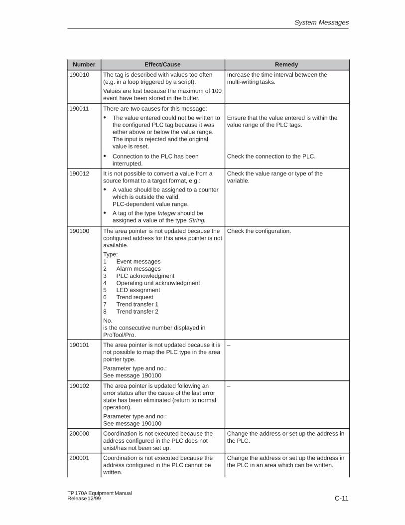
System Messages
C-11TP 170A Equipment ManualRelease 12/99
RemedyEffect/CauseNumber
190010 The tag is described with values too often(e.g. in a loop triggered by a script).
Values are lost because the maximum of 100event have been stored in the buffer.
Increase the time interval between themulti-writing tasks.
190011 There are two causes for this message:
� The value entered could not be written tothe configured PLC tag because it waseither above or below the value range.The input is rejected and the originalvalue is reset.
Ensure that the value entered is within thevalue range of the PLC tags.
� Connection to the PLC has beeninterrupted.
Check the connection to the PLC.
190012 It is not possible to convert a value from asource format to a target format, e.g.:
� A value should be assigned to a counterwhich is outside the valid,PLC-dependent value range.
� A tag of the type Integer should beassigned a value of the type String.
Check the value range or type of thevariable.
190100 The area pointer is not updated because theconfigured address for this area pointer is notavailable.
Type:1 Event messages2 Alarm messages3 PLC acknowledgment4 Operating unit acknowledgment5 LED assignment6 Trend request7 Trend transfer 18 Trend transfer 2
No.is the consecutive number displayed inProTool/Pro.
Check the configuration.
190101 The area pointer is not updated because it isnot possible to map the PLC type in the areapointer type.
Parameter type and no.:See message 190100
–
190102 The area pointer is updated following anerror status after the cause of the last errorstate has been eliminated (return to normaloperation).
Parameter type and no.:See message 190100
–
200000 Coordination is not executed because theaddress configured in the PLC does notexist/has not been set up.
Change the address or set up the address inthe PLC.
200001 Coordination is not executed because theaddress configured in the PLC cannot bewritten.
Change the address or set up the address inthe PLC in an area which can be written.
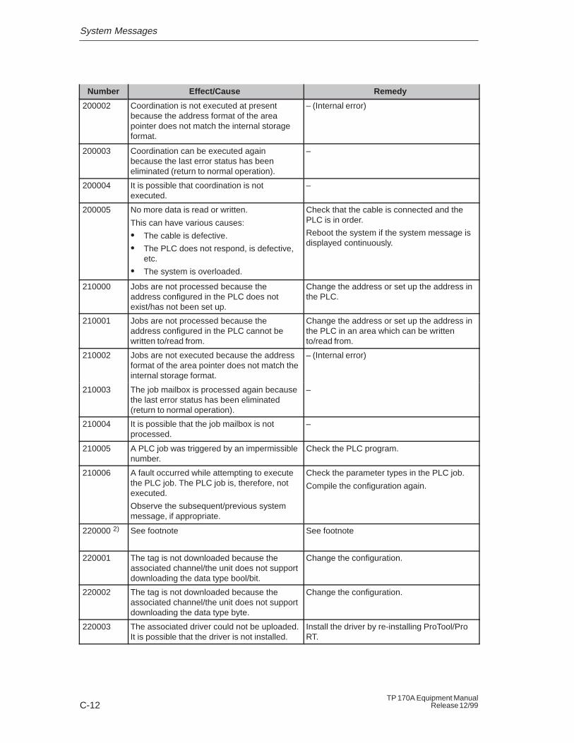
System Messages
C-12TP 170A Equipment Manual
Release 12/99
RemedyEffect/CauseNumber
200002 Coordination is not executed at presentbecause the address format of the areapointer does not match the internal storageformat.
– (Internal error)
200003 Coordination can be executed againbecause the last error status has beeneliminated (return to normal operation).
–
200004 It is possible that coordination is notexecuted.
–
200005 No more data is read or written.
This can have various causes:
� The cable is defective.
� The PLC does not respond, is defective,etc.
� The system is overloaded.
Check that the cable is connected and thePLC is in order.
Reboot the system if the system message isdisplayed continuously.
210000 Jobs are not processed because theaddress configured in the PLC does notexist/has not been set up.
Change the address or set up the address inthe PLC.
210001 Jobs are not processed because theaddress configured in the PLC cannot bewritten to/read from.
Change the address or set up the address inthe PLC in an area which can be writtento/read from.
210002 Jobs are not executed because the addressformat of the area pointer does not match theinternal storage format.
– (Internal error)
210003 The job mailbox is processed again becausethe last error status has been eliminated(return to normal operation).
–
210004 It is possible that the job mailbox is notprocessed.
–
210005 A PLC job was triggered by an impermissiblenumber.
Check the PLC program.
210006 A fault occurred while attempting to executethe PLC job. The PLC job is, therefore, notexecuted.
Observe the subsequent/previous systemmessage, if appropriate.
Check the parameter types in the PLC job.
Compile the configuration again.
220000 2) See footnote See footnote
220001 The tag is not downloaded because theassociated channel/the unit does not supportdownloading the data type bool/bit.
Change the configuration.
220002 The tag is not downloaded because theassociated channel/the unit does not supportdownloading the data type byte.
Change the configuration.
220003 The associated driver could not be uploaded.It is possible that the driver is not installed.
Install the driver by re-installing ProTool/ProRT.
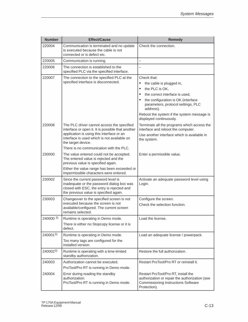
System Messages
C-13TP 170A Equipment ManualRelease 12/99
RemedyEffect/CauseNumber
220004 Communication is terminated and no updateis executed because the cable is notconnected or is defect etc.
Check the connection.
220005 Communication is running. –
220006 The connection is established to thespecified PLC via the specified interface.
–
220007 The connection to the specified PLC at thespecified interface is disconnected.
Check that:
� the cable is plugged in,
� the PLC is OK,
� the correct interface is used,
� the configuration is OK (interfaceparameters, protocol settings, PLCaddress).
Reboot the system if the system message isdisplayed continuously.
220008 The PLC driver cannot access the specifiedinterface or open it. It is possible that anotherapplication is using this interface or aninterface is used which is not available onthe target device.
There is no communication with the PLC.
Terminate all the programs which access theinterface and reboot the computer.
Use another interface which is available inthe system.
230000 The value entered could not be accepted.The entered value is rejected and theprevious value is specified again.
Either the value range has been exceeded orimpermissible characters were entered.
Enter a permissible value.
230002 Since the current password level isinadequate or the password dialog box wasclosed with ESC, the entry is rejected andthe previous value is specified again.
Activate an adequate password level usingLogin.
230003 Changeover to the specified screen is notexecuted because the screen is notavailable/configured. The current screenremains selected.
Configure the screen.
Check the selection function.
240000 3) Runtime is operating in Demo mode.
There is either no Stopcopy license or it isdefect.
Load the license.
2400013) Runtime is operating in Demo mode.
Too many tags are configured for theinstalled version.
Load an adequate license / powerpack.
2400023) Runtime is operating with a time-limitedstandby authorization.
Restore the full authorization.
240003 Authorization cannot be executed.
ProTool/Pro RT is running in Demo mode.
Restart ProTool/Pro RT or reinstall it.
240004 Error during reading the standbyauthorization.ProTool/Pro RT is running in Demo mode.
Restart ProTool/Pro RT, install theauthorization or repair the authorization (seeCommissioning Instructions SoftwareProtection).
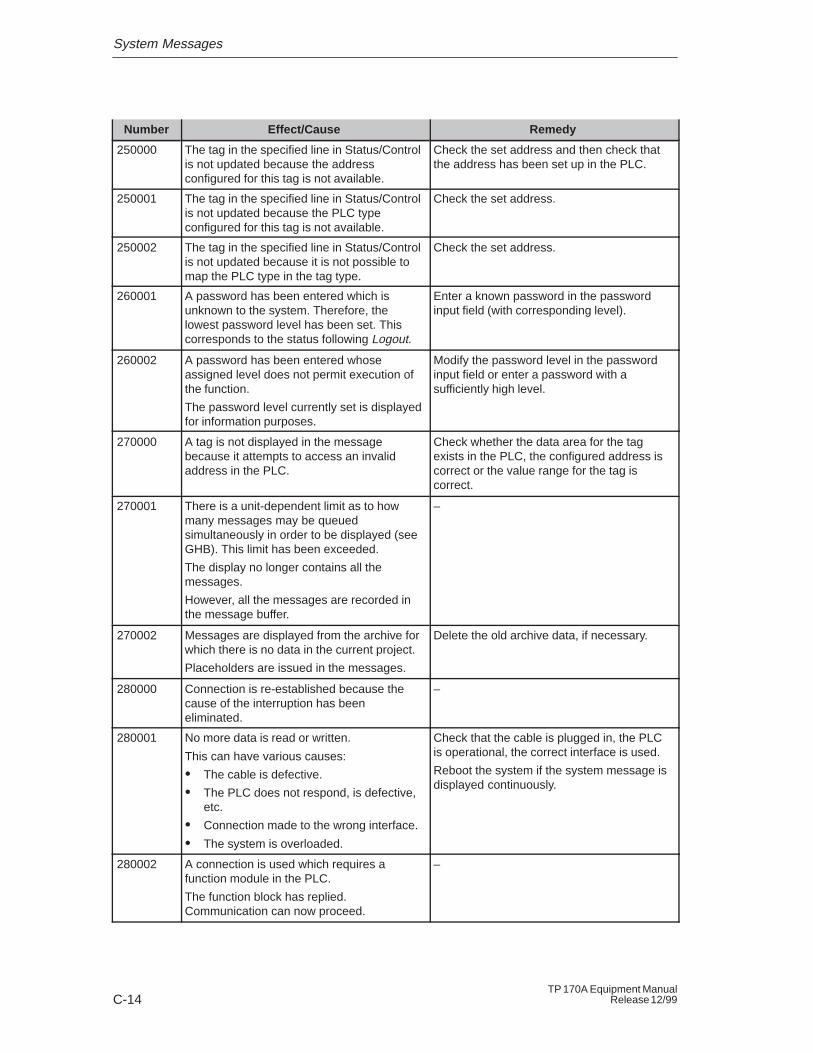
System Messages
C-14TP 170A Equipment Manual
Release 12/99
RemedyEffect/CauseNumber
250000 The tag in the specified line in Status/Controlis not updated because the addressconfigured for this tag is not available.
Check the set address and then check thatthe address has been set up in the PLC.
250001 The tag in the specified line in Status/Controlis not updated because the PLC typeconfigured for this tag is not available.
Check the set address.
250002 The tag in the specified line in Status/Controlis not updated because it is not possible tomap the PLC type in the tag type.
Check the set address.
260001 A password has been entered which isunknown to the system. Therefore, thelowest password level has been set. Thiscorresponds to the status following Logout.
Enter a known password in the passwordinput field (with corresponding level).
260002 A password has been entered whoseassigned level does not permit execution ofthe function.
The password level currently set is displayedfor information purposes.
Modify the password level in the passwordinput field or enter a password with asufficiently high level.
270000 A tag is not displayed in the messagebecause it attempts to access an invalidaddress in the PLC.
Check whether the data area for the tagexists in the PLC, the configured address iscorrect or the value range for the tag iscorrect.
270001 There is a unit-dependent limit as to howmany messages may be queuedsimultaneously in order to be displayed (seeGHB). This limit has been exceeded.
The display no longer contains all themessages.
However, all the messages are recorded inthe message buffer.
–
270002 Messages are displayed from the archive forwhich there is no data in the current project.
Placeholders are issued in the messages.
Delete the old archive data, if necessary.
280000 Connection is re-established because thecause of the interruption has beeneliminated.
–
280001 No more data is read or written.
This can have various causes:
� The cable is defective.
� The PLC does not respond, is defective,etc.
� Connection made to the wrong interface.
� The system is overloaded.
Check that the cable is plugged in, the PLCis operational, the correct interface is used.
Reboot the system if the system message isdisplayed continuously.
280002 A connection is used which requires afunction module in the PLC.
The function block has replied.Communication can now proceed.
–
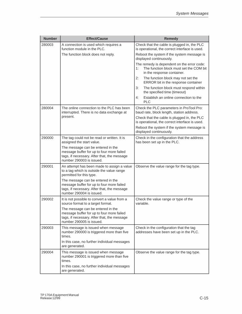
System Messages
C-15TP 170A Equipment ManualRelease 12/99
RemedyEffect/CauseNumber
280003 A connection is used which requires afunction module in the PLC.
The function block does not reply.
Check that the cable is plugged in, the PLCis operational, the correct interface is used.
Reboot the system if the system message isdisplayed continuously.
The remedy is dependent on the error code:1: The function block must set the COM bit
in the response container.
2: The function block may not set theERROR bit in the response container
3: The function block must respond withinthe specified time (timeout)
4: Establish an online connection to thePLC
280004 The online connection to the PLC has beeninterrupted. There is no data exchange atpresent.
Check the PLC parameters in ProTool Pro:baud rate, block length, station address.
Check that the cable is plugged in, the PLCis operational, the correct interface is used.
Reboot the system if the system message isdisplayed continuously.
290000 The tag could not be read or written. It isassigned the start value.
The message can be entered in themessage buffer for up to four more failedtags, if necessary. After that, the messagenumber 290003 is issued.
Check in the configuration that the addresshas been set up in the PLC.
290001 An attempt has been made to assign a valueto a tag which is outside the value rangepermitted for this type.
The message can be entered in themessage buffer for up to four more failedtags, if necessary. After that, the messagenumber 290004 is issued.
Observe the value range for the tag type.
290002 It is not possible to convert a value from asource format to a target format.
The message can be entered in themessage buffer for up to four more failedtags, if necessary. After that, the messagenumber 290005 is issued.
Check the value range or type of thevariable.
290003 This message is issued when messagenumber 290000 is triggered more than fivetimes.
In this case, no further individual messagesare generated.
Check in the configuration that the tagaddresses have been set up in the PLC.
290004 This message is issued when messagenumber 290001 is triggered more than fivetimes.
In this case, no further individual messagesare generated.
Observe the value range for the tag type.
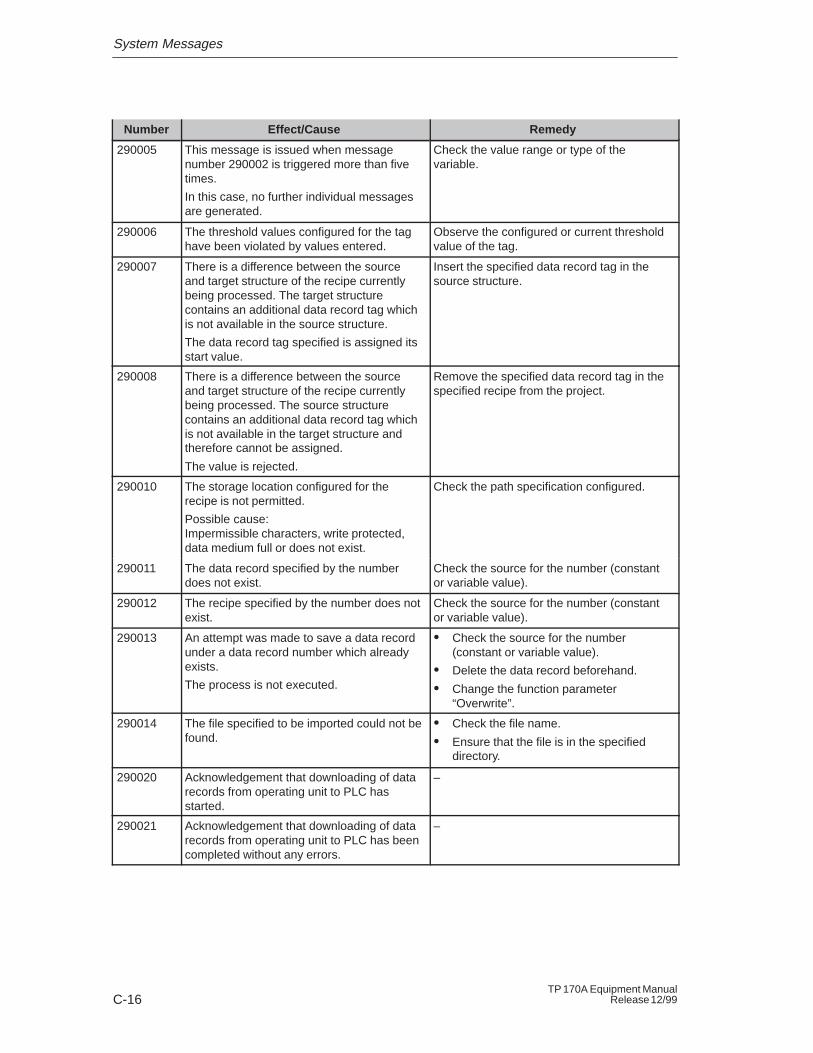
System Messages
C-16TP 170A Equipment Manual
Release 12/99
RemedyEffect/CauseNumber
290005 This message is issued when messagenumber 290002 is triggered more than fivetimes.
In this case, no further individual messagesare generated.
Check the value range or type of thevariable.
290006 The threshold values configured for the taghave been violated by values entered.
Observe the configured or current thresholdvalue of the tag.
290007 There is a difference between the sourceand target structure of the recipe currentlybeing processed. The target structurecontains an additional data record tag whichis not available in the source structure.
The data record tag specified is assigned itsstart value.
Insert the specified data record tag in thesource structure.
290008 There is a difference between the sourceand target structure of the recipe currentlybeing processed. The source structurecontains an additional data record tag whichis not available in the target structure andtherefore cannot be assigned.
The value is rejected.
Remove the specified data record tag in thespecified recipe from the project.
290010 The storage location configured for therecipe is not permitted.
Possible cause:Impermissible characters, write protected,data medium full or does not exist.
Check the path specification configured.
290011 The data record specified by the numberdoes not exist.
Check the source for the number (constantor variable value).
290012 The recipe specified by the number does notexist.
Check the source for the number (constantor variable value).
290013 An attempt was made to save a data recordunder a data record number which alreadyexists.
The process is not executed.
� Check the source for the number(constant or variable value).
� Delete the data record beforehand.
� Change the function parameter “Overwrite”.
290014 The file specified to be imported could not befound.
� Check the file name.
� Ensure that the file is in the specifieddirectory.
290020 Acknowledgement that downloading of datarecords from operating unit to PLC hasstarted.
–
290021 Acknowledgement that downloading of datarecords from operating unit to PLC has beencompleted without any errors.
–
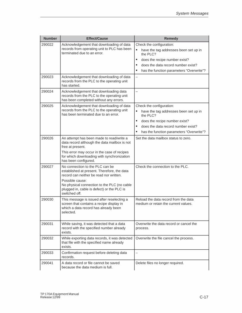
System Messages
C-17TP 170A Equipment ManualRelease 12/99
RemedyEffect/CauseNumber
290022 Acknowledgement that downloading of datarecords from operating unit to PLC has beenterminated due to an error.
Check the configuration:
� have the tag addresses been set up inthe PLC?
� does the recipe number exist?
� does the data record number exist?
� has the function parameters “Overwrite”?
290023 Acknowledgement that downloading of datarecords from the PLC to the operating unithas started.
–
290024 Acknowledgement that downloading datarecords from the PLC to the operating unithas been completed without any errors.
–
290025 Acknowledgement that downloading of datarecords from the PLC to the operating unithas been terminated due to an error.
Check the configuration:
� have the tag addresses been set up inthe PLC?
� does the recipe number exist?
� does the data record number exist?
� has the function parameters “Overwrite”?
290026 An attempt has been made to read/write adata record although the data mailbox is notfree at present.
This error may occur in the case of recipesfor which downloading with synchronizationhas been configured.
Set the data mailbox status to zero.
290027 No connection to the PLC can beestablished at present. Therefore, the datarecord can neither be read nor written.
Possible cause:No physical connection to the PLC (no cableplugged in, cable is defect) or the PLC isswitched off.
Check the connection to the PLC.
290030 This message is issued after reselecting ascreen that contains a recipe display inwhich a data record has already beenselected.
Reload the data record from the datamedium or retain the current values.
290031 While saving, it was detected that a datarecord with the specified number alreadyexists.
Overwrite the data record or cancel theprocess.
290032 While exporting data records, it was detectedthat file with the specified name alreadyexists.
Overwrite the file cancel the process.
290033 Confirmation request before deleting datarecords.
–
290041 A data record or file cannot be savedbecause the data medium is full.
Delete files no longer required.
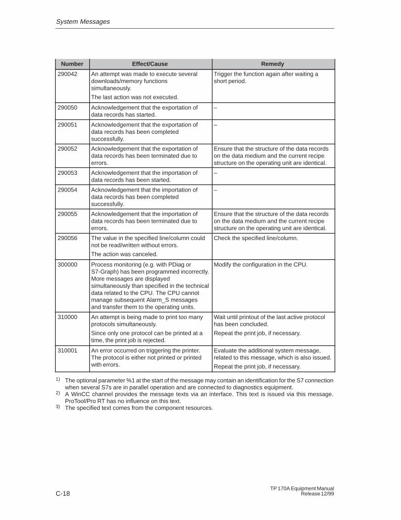
System Messages
C-18TP 170A Equipment Manual
Release 12/99
RemedyEffect/CauseNumber
290042 An attempt was made to execute severaldownloads/memory functionssimultaneously.
The last action was not executed.
Trigger the function again after waiting ashort period.
290050 Acknowledgement that the exportation ofdata records has started.
–
290051 Acknowledgement that the exportation ofdata records has been completedsuccessfully.
–
290052 Acknowledgement that the exportation ofdata records has been terminated due toerrors.
Ensure that the structure of the data recordson the data medium and the current recipestructure on the operating unit are identical.
290053 Acknowledgement that the importation ofdata records has been started.
–
290054 Acknowledgement that the importation ofdata records has been completedsuccessfully.
–
290055 Acknowledgement that the importation ofdata records has been terminated due toerrors.
Ensure that the structure of the data recordson the data medium and the current recipestructure on the operating unit are identical.
290056 The value in the specified line/column couldnot be read/written without errors.
The action was canceled.
Check the specified line/column.
300000 Process monitoring (e.g. with PDiag orS7-Graph) has been programmed incorrectly.More messages are displayedsimultaneously than specified in the technicaldata related to the CPU. The CPU cannotmanage subsequent Alarm_S messagesand transfer them to the operating units.
Modify the configuration in the CPU.
310000 An attempt is being made to print too manyprotocols simultaneously.
Since only one protocol can be printed at atime, the print job is rejected.
Wait until printout of the last active protocolhas been concluded.
Repeat the print job, if necessary.
310001 An error occurred on triggering the printer.The protocol is either not printed or printedwith errors.
Evaluate the additional system message,related to this message, which is also issued.
Repeat the print job, if necessary.
1) The optional parameter %1 at the start of the message may contain an identification for the S7 connectionwhen several S7s are in parallel operation and are connected to diagnostics equipment.
2) A WinCC channel provides the message texts via an interface. This text is issued via this message.ProTool/Pro RT has no influence on this text.
3) The specified text comes from the component resources.
System Messages
C-19TP 170A Equipment ManualRelease 12/99
Procedure in the case of “internal errors”
Please proceed as follows in the case of all system messages related to “internalerrors”:
1. Start up the operating unit again.
2. Download the configuration again.
3. Switch the operating unit off, stop the PLC and then restart both.
4. If the error occurs again, please contact the SIMATIC Customer Support. Makereference to the specified error number and message tags.

System Messages
C-20TP 170A Equipment Manual
Release 12/99

D-1TP 170A Equipment ManualRelease 12/99
ESD-Guidelines
What does ESD mean?
Virtually all present-day modules incorporate highly integrated MOS devices orcomponents. For technological reasons, these electronic components are verysensitive to overvoltages and consequently therefore to electrostatic discharge:
These devices are referred to in German as Elektrostatisch GefährdetenBauelemente/ Baugruppen: ”EGB”
The more frequent international name is:
”ESD” (Electrostatic Sensitive Device)
The following symbol on plates on cabinets, mounting racks or packages drawsattention to the use of electrostatic sensitive devices and thus to the contactsensitivity of the assemblies concerned:
ESDs may be destroyed by voltages and energies well below the perceptionthreshold of persons. Voltages of this kind occur as soon as a device or anassembly is touched by a person who is not electrostatically discharged . Devicesexposed to such overvoltages cannot immediately be detected as defective in themajority of cases since faulty behavior may occur only after a long period ofoperation.
Precautions against electrostatic discharge
Most plastics are capable of carrying high charges and it is therefore imperativethat they be kept away from sensitive components.
When handling electrostatic sensitive devices, make sure that persons, workplacesand packages are properly grounded.
D
ESD-Guidelines
D-2TP 170A Equipment Manual
Release 12/99
Handling ESD assemblies
A general rule is that assemblies should be touched only when this cannot beavoided owing to the work that has to performed on them. Under no circumstancesshould you handle printed-circuit boards by touching device pins or circuitry.
You should touch devices only if
� you are grounded by permanently wearing an ESD wrist strap or
� you are wearing ESD shoes or ESD shoe-grounding protection straps inconjunction with an ESD floor.
Before you touch an electronic assembly, your body must be discharged. Thesimplest way of doing this is to touch a conductive, grounded object immediatelybeforehand – for example, bare metal parts of a cabinet, water pipe etc.
Assemblies should not be brought into contact with charge-susceptible and highlyinsulating materials such as plastic films, insulating table tops and items of clothingetc. containing synthetic fibers.
Assemblies should be deposited only on conductive surfaces (tables with an ESDcoating, conductive ESD cellular material, ESD bags, ESD shipping containers).
Do not place assemblies near visual display units, monitors or television sets(minimum distance to screen > 10 cm).
Measuring and modifying ESD assemblies
Perform measurements on ESD assemblies only when
� the measuring instrument is grounded – for example, by means of a protectiveconductor – or
� the measuring head has been briefly discharged before measurements aremade with a potential-free measuring instrument – for example, by touching abare metal control cabinet.
When soldering, use only grounded soldering irons.
Shipping ESD assemblies
Always store and ship assemblies and devices in conductive packing – forexample, metallized plastic boxes and tin cans.
If packing is not conductive, assemblies must be conductively wrapped before theyare packed. You can use, for example, conductive foam rubber, ESD bags,domestic aluminum foil or paper (never use plastic bags or foils).
With assemblies containing fitted batteries, make sure that the conductive packingdoes not come into contact with or short-circuit battery connectors. If necessary,cover the connectors beforehand with insulating tape or insulating material.
E-1TP 170A Equipment ManualRelease 12/99
SIMATIC HMI Documentation
Target groups
This manual is part of the SIMATIC HMI documentation. The documentation isaimed at the following target groups:
� Newcomers
� Users
� Configurers
� Programmers
� Commissioning engineers
How the documentation is organized
The SIMATIC HMI documentation consists of the following components:
� User’s Guides for:
– Configuration software
– Runtime software
– Communication between PLCs and operating units
� Equipment Manuals for the following operating units:
– SIMATIC PC
– MP (Multi Panel)
– OP (Operator Panel)
– TP (Touch Panel)
– TD (Text Display)
– PP (Push Button Panel)
� Online Help on the configuration software
� Start-up Guides
� First Steps
Overview of complete documentation
The following table provides an overview of the SIMATIC HMI documentation andshows you when you require the different documents.
E
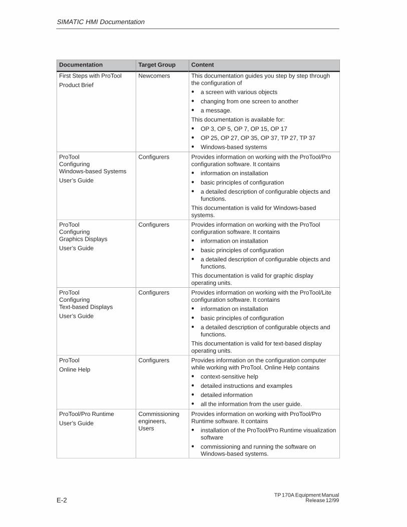
SIMATIC HMI Documentation
E-2TP 170A Equipment Manual
Release 12/99
Documentation Target Group Content
First Steps with ProTool
Product Brief
Newcomers This documentation guides you step by step throughthe configuration of
� a screen with various objects
� changing from one screen to another
� a message.
This documentation is available for:
� OP 3, OP 5, OP 7, OP 15, OP 17
� OP 25, OP 27, OP 35, OP 37, TP 27, TP 37
� Windows-based systems
ProToolConfiguring Windows-based Systems
User’s Guide
Configurers Provides information on working with the ProTool/Proconfiguration software. It contains
� information on installation
� basic principles of configuration
� a detailed description of configurable objects andfunctions.
This documentation is valid for Windows-basedsystems.
ProToolConfiguring Graphics Displays
User’s Guide
Configurers Provides information on working with the ProToolconfiguration software. It contains
� information on installation
� basic principles of configuration
� a detailed description of configurable objects andfunctions.
This documentation is valid for graphic displayoperating units.
ProToolConfiguring Text-based Displays
User’s Guide
Configurers Provides information on working with the ProTool/Liteconfiguration software. It contains
� information on installation
� basic principles of configuration
� a detailed description of configurable objects andfunctions.
This documentation is valid for text-based displayoperating units.
ProTool
Online Help
Configurers Provides information on the configuration computerwhile working with ProTool. Online Help contains
� context-sensitive help
� detailed instructions and examples
� detailed information
� all the information from the user guide.
ProTool/Pro Runtime
User’s Guide
Commissioningengineers, Users
Provides information on working with ProTool/ProRuntime software. It contains
� installation of the ProTool/Pro Runtime visualizationsoftware
� commissioning and running the software onWindows-based systems.
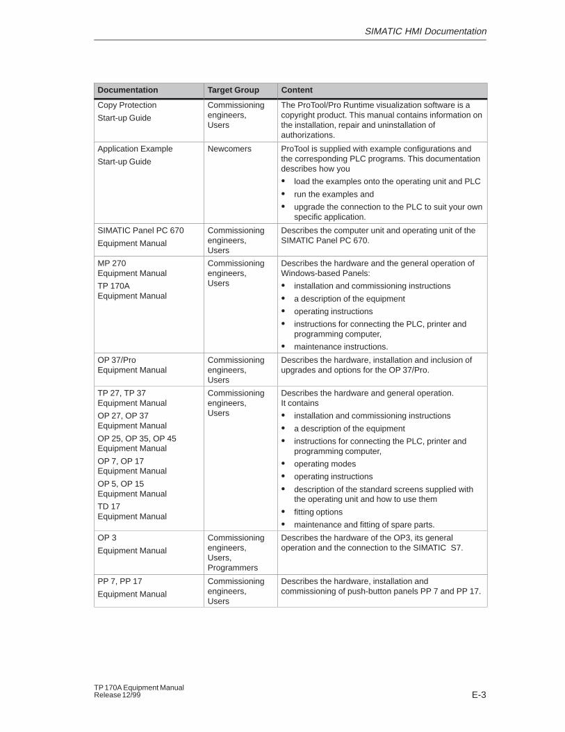
SIMATIC HMI Documentation
E-3TP 170A Equipment ManualRelease 12/99
ContentTarget GroupDocumentation
Copy Protection
Start-up Guide
Commissioningengineers, Users
The ProTool/Pro Runtime visualization software is acopyright product. This manual contains information onthe installation, repair and uninstallation ofauthorizations.
Application Example
Start-up Guide
Newcomers ProTool is supplied with example configurations andthe corresponding PLC programs. This documentationdescribes how you
� load the examples onto the operating unit and PLC
� run the examples and
� upgrade the connection to the PLC to suit your ownspecific application.
SIMATIC Panel PC 670
Equipment Manual
Commissioningengineers, Users
Describes the computer unit and operating unit of theSIMATIC Panel PC 670.
MP 270Equipment Manual
TP 170AEquipment Manual
Commissioningengineers, Users
Describes the hardware and the general operation ofWindows-based Panels:
� installation and commissioning instructions
� a description of the equipment
� operating instructions
� instructions for connecting the PLC, printer andprogramming computer,
� maintenance instructions.
OP 37/ProEquipment Manual
Commissioningengineers, Users
Describes the hardware, installation and inclusion ofupgrades and options for the OP 37/Pro.
TP 27, TP 37Equipment Manual
OP 27, OP 37Equipment Manual
OP 25, OP 35, OP 45Equipment Manual
OP 7, OP 17Equipment Manual
OP 5, OP 15Equipment Manual
TD 17Equipment Manual
Commissioningengineers, Users
Describes the hardware and general operation. It contains
� installation and commissioning instructions
� a description of the equipment
� instructions for connecting the PLC, printer andprogramming computer,
� operating modes
� operating instructions
� description of the standard screens supplied withthe operating unit and how to use them
� fitting options
� maintenance and fitting of spare parts.
OP 3
Equipment Manual
Commissioningengineers, Users, Programmers
Describes the hardware of the OP3, its generaloperation and the connection to the SIMATIC S7.
PP 7, PP 17
Equipment Manual
Commissioningengineers, Users
Describes the hardware, installation andcommissioning of push-button panels PP 7 and PP 17.
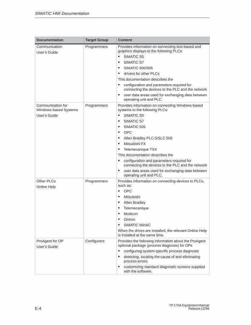
SIMATIC HMI Documentation
E-4TP 170A Equipment Manual
Release 12/99
ContentTarget GroupDocumentation
Communication
User’s Guide
Programmers Provides information on connecting text-based andgraphics displays to the following PLCs:
� SIMATIC S5
� SIMATIC S7
� SIMATIC 500/505
� drivers for other PLCs
This documentation describes the
� configuration and parameters required forconnecting the devices to the PLC and the network
� user data areas used for exchanging data betweenoperating unit and PLC.
Communication for Windows-based Systems
User’s Guide
Programmers Provides information on connecting Windows-basedsystems to the following PLCs:
� SIMATIC S5
� SIMATIC S7
� SIMATIC 505
� OPC
� Allen Bradley PLC-5/SLC 500
� Mitsubishi FX
� Telemecanique TSX
This documentation describes the
� configuration and parameters required forconnecting the devices to the PLC and the network
� user data areas used for exchanging data betweenoperating unit and PLC.
Other PLCs
Online Help
Programmers Provides information on connecting devices to PLCs,such as:
� OPC
� Mitsubishi
� Allen Bradley
� Telemecanique
� Modicon
� Omron
� SIMATIC WinAC
When the drives are installed, the relevant Online Helpis installed at the same time.
ProAgent for OP
User’s Guide
Configurers Provides the following information about the ProAgentoptional package (process diagnosis) for OPs
� configuring system-specific process diagnosis
� detecting, locating the cause of and eliminatingprocess errors,
� customizing standard diagnostic screens suppliedwith the software.
Glossary-1TP 170A Equipment ManualRelease 12/99
Glossary
Acknowledgement
Acknowledgement of an alarm message on the operating unit confirms that it hasbeen noted. After acknowledgement, the message disappears from the screen.
Alarm message
Provides information on the operating unit concerning operating errors on themachine or system connected to the PLC. The message text may also containcurrent measured values.
Since alarm messages indicate abnormal operating statues, they must beacknowledged.
Alarm time
Time interval between the arrival and departure of an alarm message.
Area pointer
Defines a memory area in the PLC for data exchange between the PLC andoperating unit.
Bar graphs
Represent values from the PLC as rectangular areas. This is a way of displayingfilling levels or workpiece numbers, for example, on the operating unit.
Baud rate
Rate of speed at which data is downloaded. Baud rate is specified in Bit/s.
Glossary
Glossary-2TP 170A Equipment Manual
Release 12/99
Blank
Switch off or fade out the screen saver.
Boot
A loading process which downloads the operating system in the working memoryof the operating unit
Configuration
Definition of system-specific default settings, messages and screens using theconfiguration software ProTool .
Download
The transfer of run-capable project data to the operating unit. Connect theoperating unit to the configuration computer with a standard cable beforehand.
Download mode
Operating unit operating mode in which data can be downloaded from theconfiguration computer to the operating unit (also refer to Download ).
Event message
Provides information on the operating unit concerning the operating statuses of themachine or system connected to the PLC. The message text may also containcurrent measured values.
Glossary
Glossary-3TP 170A Equipment ManualRelease 12/99
Fixed window
The window which always appears at the top of the operating unit screen. Thecontent of the fixed window is independent of the screen currently open.
Flash memory
Programmable memory which can be electrically deleted and written to againsegment-by-segment.
Half Brightness Life
The period of time after which the brightness tube only achieves 50% of theoriginal value.
Help text
Configurable, additional information on messages, screens and fields. The helptext concerning an alarm message can, for example, contain information on thecause of the fault and methods of elimination.
Icon
Configured graphic symbol identifying the function of a function key.
Input field
Enables the user to enter values which are subsequently downloaded to the PLC.
Logout time
Configurable interval of time after which the password level is reset to zero whenthe operating unit is not used.
Glossary
Glossary-4TP 170A Equipment Manual
Release 12/99
Message arrival
Time at which a message was triggered by the PLC or operating unit.
Message departure
Time at which a message was withdrawn by the PLC.
Message event
Message events consist of:
� Message arrival
� Message acknowledgement
� Message departure
Message indicator
A graphical symbol displayed on the operating unit when at least one alarmmessage is present .
Message logging
Printout of alarm and event messages parallel to their display on the operating unitdisplay.
Multi Panel
Multi-functional, configurable operating unit with graphics display and Windows�CE operating system for operating and monitoring machines and systems.
Normal operation
Operating unit operating mode in which messages are displayed and screens canbe operated.
Glossary
Glossary-5TP 170A Equipment ManualRelease 12/99
Operator Panel
Operating unit which can be configured for operating and monitoring machines andsystems.
Output field
Displays current values from the PLC on the operating unit.
Password
A character string which must be entered on the operating unit before a protectedfunction can be activated. Each password is assigned to a password level .
Password level
Defines the user’s rights. The rights are in hierarchical steps from Level 0 (lowestlevel) to Level 9 (highest level). The password level linked to the passwordallocates the rights to execute functions on the operating unit belonging to thatlevel or lower.
PCL
Hewlett� Packard (Printer Control Language).
PCMCIA
Personal Computer Memory Card International Association
Joint operation of computer companies with the aim of defining one internationalstandard for memory cards and PC expansion cards. Cooperation with JEIDA .
PLC
General term for units and systems with which the operating unit communicates(e.g. SIMATIC S7 or PC).
PLC job
PLC jobs can be used by the PLC to trigger functions on the operating unit, e.g.display a screen.
Glossary
Glossary-6TP 170A Equipment Manual
Release 12/99
Power-up test
Checks the status of the CPU and memory each time the power is switched on.
Print screen
Printout of a copy of the screen contents.
Process screen
The display of process values and process progress on the operating unit in theform of screens, which may contain graphics, texts and values.
Programmable controller
PLC from the SIMATIC S5 series (e.g. AG S5-115U/135U).
Programmable system
PLC from the SIMATIC S7 series (SIMATIC S7-200/300/400).
ProTool
Full graphics based configuration software for the whole SIMATIC HMI unit rangeand for Windows-based systems.
Remaining buffer
Configurable size of the message buffer. In the case of buffer overflow, theoperating unit deletes message events until the configured remaining buffercapacity is reached.
RS232
Standard interface for serial data transfer at a defined voltage level. Transmitterand receiver are electrically connected.
RS485
Standard interface for serial data transfer at a very high transmission rate.
Glossary
Glossary-7TP 170A Equipment ManualRelease 12/99
Screen
A screen displays all the logically related process data on the operating unit,whereby the individual values can be modified.
Selection field
Contains a list of entries from which one can be selected on the operating unit.
Start screen
The first screen, which automatically appears after theoperating unit has startedup.
Status button
The Status button is a configurable display and operating element which can haveone of two states: ON and OFF, i.e. touched and untouched . Text or graphicscan be configured for both states which then appear on the Status buto
Status/Force tag
Screen object with which individual address areas in the connected SIMATIC S5 orSIMATIC S7 can be accessed for reading and writing directly from the operatingunit.
Superuser
A user with permissions to trigger functions of the highest password level . Thesuperuser has access to all the operating unit functions.
System message
Provides information on the operating unit concerning internal statuses of theoperating unit and PLC.
Glossary
Glossary-8TP 170A Equipment Manual
Release 12/99
Tag
A defined memory location in which values can be read from and written to. Thiscan be performed from the PLC or via the operating unit. Depending on whetherthe tag is linked to the PLC or not, a distinction is made between “global” tags(process tags) and “local” tags.
Touch panel
This is an operating unit without a keyboard. The touch panel (abbreviated to TP)is operated via the contact-sensitive screen elements.
Trend curve
Represents values from the PLC on the screen as a continuous line or bar.
TTY
Standard interface for serial data transfer at a defined current level. Transmitterand receiver are electrically connected.
Index-1TP 170A Equipment ManualRelease 12/99
Index
AAcknowledgement, on touching, 4-3Adjust_Contrast, Function, 6-4Air discharge, A-4Ambient conditions, A-3Angle of inclination, 7-2, A-3Approvals, A-5Area of use, 1-1Area Pointer, Date/Time PLC, 5-6Arrangement, Connection elements, 8-3Assignment of interfaces, B-1Authorization, 5-7Automatic downloading, 3-4
BBack–lighting, Screen, 1-4, A-2Bar graph, 5-2Barometric pressure, A-3Burst interference, A-4
CCable cross–section, 7-6Cables, 7-4Calibration screen, 6-3Change_mode, Function, 6-2Changed, event, 5-3Character, delete, 4-5Character alignment, 4-5Characters, enter, 4-5Cleaning, Unit, 9-1Cleaning agents, 9-1Clock frequency, 1-4, A-2Commissioning, 3-1Communication, 2-1Communication options, 8-4Compatibility conflict, 3-2, 3-3, 10-1Condensation, 7-2Conduction, RF, A-4
ConfigurationLoad, 3-2Simulation, 3-7Test, 3-7
Configuration computer, 1-3, 7-5Connect, 7-7
Configuration menu, 3-5, 6-3Configuration options, 7-5Configuration phase, 1-3Configuration software, 1-2Configure, Interface IF1B, 7-9Conflict, Compatibility, 3-2, 3-3, 10-1Connect
Configuration computer, 7-7PLC, 7-8
Connecting, Power supply, 7-6Connection
To configuration computer, 7-7To PLC, 6-2, 7-8
Connection elements, 8-3Connections, Electrical, 7-4Connector pin–out, B-1Contact discharge, A-4Contrast, 2-1
Set, 6-3Cross–section, Power supply, 7-6cUL approval, A-5Cut–out, Installation, A-2
DData, Technical, A-1Date and Time, 5-6Decimal point, entering, 4-5Degree of protection, 1-1, 7-2, A-2DEL, 4-5Depth, Installation, A-2Description, Unit, 8-1Digits, enter, 4-5DIL switch, 7-5, 7-9, 8-3Dimensions, 8-2, A-2
Index
Index-2TP 170A Equipment Manual
Release 12/99
Discharge, Static, A-4Display, 1-4, A-2
Set contrast, 6-3Documentation, E-1Download, Operating mode, 6-2Download mode, 3-3
options, 3-5Dynamic screen partitions, 4-6
EElectrical connections, 7-4Electrical Installation, 7-4EMC–compatible installation, 7-4ENTER, 4-5Entering, Values, 4-4ESC, 4-5ESD Guidelines, D-1Event messages, 5-5Events, 5-3External dimensions, A-2
FFilter criteria, Message view, 5-6Fixation, 7-3Flash memory, A-2FM Approval, A-5Front panel, Thickness, 7-2, 8-2Front view, TP27–6, 8-2Functionality, 2-1Functions
Adjust_Contrast, 6-4Change_mode, 6-2Logoff_User, 5-7Logon_User, 5-7Touch_Calibration, 6-4
Fuse, A-2
GGeneral operation, 4-1Graphic, 5-2Grounding, 7-6Grounding connection, 7-5, 7-6, 8-3Grounding screw, 7-6Guidelines
EEC, A-3ESD, D-1
HHalf Brightness Life, 1-4Hazardous area, A-5Hexadecimal digits, enter, 4-5Housing, A-2Humidity, A-3
IIF1A interface, Assignment, B-1IF1B interface, Assignment, B-1Initial startup, 3-2Input
cancel, 4-5confirm, 4-5
Input field, 4-4, 5-2Installation, 7-1
Configuration computer, 7-7Electrical, 7-4In front panels, 7-3Mechanical, 7-2PLC, 7-8
Installation conditions, 7-2Installation location, 1-1, 7-2Interface Assignment, B-1Interfaces, 1-4, 8-3
Configure IF1B, 7-9IF1A, 7-7, 7-8IF1B, 7-7, 7-8
Interference–free, 7-4Introduction, 1-1Irradiation, RF, A-4Isolation, Electrical, 7-6
LLCD type, A-2Limit value monitoring, 2-1Limit values, 4-5Literature, 1-4, E-1Load, Configuration, 3-2Location, A-3Logoff, 5-7Logoff time, 5-7Logoff_User, Function, 5-7Logon, 5-7Logon_User, Function, 5-7Low–voltage, 7-6
Index
Index-3TP 170A Equipment ManualRelease 12/99
MMaintenance, 9-1Manual downloading, 3-3Mechanical installation, 7-2Memory, 1-4, A-2
configuration, 2-1Message acquisition, 2-1Message arrival, 5-5Message category, C-2Message departure, 5-5Message events, 5-5Message number, C-1Message view, 5-2, 5-6Messages, 2-1, 5-5Model, Overview, 1-4Monochrome, 1-4, A-2Mounting cut–out, 7-3, 8-2, A-2Mounting depth, A-2Move input position
left, 4-5right, 4-5
MPI, 2-1
NNoise immunity, A-4Number, Messages, 2-1Numeric keypad
changing sign, 4-5entering decimal point, 4-5
OOff state, Status button, 5-3Offline, Operating mode, 6-2OnButtonDown, event, 5-3OnButtonUp, Event, 5-3Online, Operating mode, 6-2Operate, touch element, 4-2Operating, Screens, 4-6Operating concept, 4-2Operating mode
Download, 6-2Offline, 6-2Online, 6-2Setting, 6-2
Operating Screens, 4-6Operating system, A-2
Operating system update, 10-1Operation
general, 4-1Screen objects, 5-1Unauthorized, 5-7
Operation acknowledgement, 4-3Optimization, Contrast, 6-3Output field, 5-2Overheating, 7-2
PPassword protection, 2-1, 5-7PC, 1-3
connection, 7-7Pin array, 7-6Pin assignment, B-1Plan view, TP27–6, 8-2PLC, 7-5
Connect, 7-8Plug connections, 7-4Pocket calculator format, 4-5Power cables, 7-4Power consumption, A-2Power supply, 7-5, 7-6, 8-3, A-2Power supply unit, 7-6Principles, Entering Values, 4-4Process control phase, 1-3Processor type, 1-4, A-2PROFIBUS–DP, 7-5, 7-7, 7-8Protection, Password, 5-7Protective foil, 9-1ProTool, 1-2PTUpdate, Utility program, 10-1PU, 1-3
connection, 7-7Pulse modulation, A-4Push button, Status button, 5-3
RRadio interference, A-4Radio interference level, A-4Rated voltage, A-2Recommissioning, 3-3Relative humidity, A-3Resolution, Display, 1-4, A-2RF conduction, A-4
Index
Index-4TP 170A Equipment Manual
Release 12/99
RF irradiation, A-4RTS signal, 7-9
SScreen, A-2
Set contrast, 6-3Screen area, Display, 1-4, A-2Screen calibration, perform, 6-3Screen objects, 4-6
operating, 5-1Overview, 5-2
Screen partitions, 4-6Screen settings, 2-1Screw–type clamp, 7-3Seal, 7-2, 7-3Serial zero modem cable, 10-1Settings
Calibration of the screen, 6-3Contrast, 6-3Operating mode, 6-2System, 6-1
Shock loading, A-3Side view, TP27–6, 8-2Sign, changing, 4-5Signal lines, 7-4SIMATIC HMI documentation, E-1SIMATIC S7, 2-1Simulator, 3-7Software, 1-4, A-2Standard cable, 7-7Standards, A-3Start downloading automatically, 3-4Start downloading manually, 3-3Start menu, 3-5Start screen, 3-2, 3-3Static discharge, A-4Static screen partitions, 4-6Status button, 5-2, 5-3Structure of the documentation, E-1Sub–D socket, B-1Sunlight, 7-2Switch, Status button, 5-3Switch settings, DIL switch, 7-9Synchronize, Date/Time, 5-6System keyboard, 4-4System messages, 5-5
List, C-1
System settings, 6-1
TTarget groups, E-1Technical Data, A-1Terminal block, 7-6Test, Configuration, 3-7Text, static, 5-2Thickness, Front panel, 7-2, 8-2Time and date, 5-6Torque, 7-3Touch calibration, 2-1Touch element
Definition, 4-2operating, 4-2
Touch_Calibration, Function, 6-4Transients, A-2
UUL Approval, A-5Unauthorized use, 5-7Unit Description, 8-1Unit dimensions, 8-2Update, Operating system, 10-1Upkeep, 9-1Utility program, PTUpdate, 10-1
VVentilation slits, 7-2Vibration, A-3Visual acknowledgement, 4-3
WWeight, A-2Windows CE, 1-1, A-2Working memory, 1-4, A-2
ZZero modem cable, 10-1


![tplinkextender.net Server tplinkextender.net UP …...TP-LINK POCKET 3040 137800 TP-LINK 217755 TP-LINK 4234CC Testil C] set MAC Manually Operation Mode Choose Region Wireless Settings](https://img.dokumen.tips/doc/110x75/5f2c960811757b532b440472/server-up-tp-link-pocket-3040-137800-tp-link-217755-tp-link-4234cc-testil-c.jpg)


![Federal Civil Procedure 170A 1771 - Leasing Newsleasingnews.org/PDF/WellsFargoCase_62014.pdf · Fed.Rules Civ.Proc.Rule 12(b)(6), (c), 28 U.S.C.A. [3] Federal Civil Procedure 170A](https://img.dokumen.tips/doc/110x75/5fa12e57e4548a5665309a91/federal-civil-procedure-170a-1771-leasing-fedrules-civprocrule-12b6-c.jpg)