Embed Size (px)
Citation preview

Torque Motors
RKI Series

2
IDAM Direct Drives: Precise. Fast. Efficient.
IDAM uses specially developed tools to develop and design the motors, including
tools for magnetic, mechanical and thermal simulation. This produces results that
our customers can use to optimise their subsequent designs.
Linear direct drives Rotary direct drives Multi-axis positioning systems
INA – Drives & Mechatronics AG & Co. KG,
a member of the Schaeffler Group, is a
specialist in linear and rotary direct
drives. To complement these products,
we also offer directly driven positioning
systems and all the necessary control-
lers and mechatronic assemblies.
In addition to standard products, IDAM
also develops and produces customised
drive solutions.
In modern machines and equipment,
direct drives are increasingly replacing
standard drive solutions because of
ever-stricter requirements for dynamics,
precision and cost-effectiveness.
Directly linking the motor and the mov-
ing mass increases the dynamic and
static rigidity, enabling high-perform-
ance positioning movements.
Direct drives are low wearing. This
allows maintenance and operating costs
to be reduced whilst also increas ing
availability.
Teams at IDAM have been developing
and producing direct drives and complex
drive systems for the following sectors:
machine tools and production machin-
ery, automation, productronics/semi-
con, measuring technology and medical
engineering for over 20 years.
Models and simulations are integrated
into the development process for direct
drives and positioning systems, making
the process more efficient.
IDAM has a state-of-the-art quality
man agement system. At IDAM, quality
man agement is a dynamic process that
is checked daily and continuously
im proved. IDAM is certified to DIN EN
ISO 9001:2008.

3
Contents
Product Range
Benefits of Rotary Direct Drives . . . . . . . . . . . . . . . . . . . . . . . . . . . . . . . . . . . . . . . . . . . . . . . . . . . . . . . . . . . . . . . . . . . . . . . . . . . . . . . . . . 4
RKI Torque Motors – Features, advantages, applications . . . . . . . . . . . . . . . . . . . . . . . . . . . . . . . . . . . . . . . . . . . . . . . . . . . . . . . . . . . . . 5
RKI Torque Motors – Design, torque, cogging torques, active force pulsation. . . . . . . . . . . . . . . . . . . . . . . . . . . . . . . . . . . . . . . . . . . . . 6
RKI Torque Motors – Winding adaptation, efficiency . . . . . . . . . . . . . . . . . . . . . . . . . . . . . . . . . . . . . . . . . . . . . . . . . . . . . . . . . . . . . . . . . 7
Torque-Rotary Speed Characteristic. . . . . . . . . . . . . . . . . . . . . . . . . . . . . . . . . . . . . . . . . . . . . . . . . . . . . . . . . . . . . . . . . . . . . . . . . . . . . . . 8
RKI Series – Torque ranges. . . . . . . . . . . . . . . . . . . . . . . . . . . . . . . . . . . . . . . . . . . . . . . . . . . . . . . . . . . . . . . . . . . . . . . . . . . . . . . . . . . . . . 9
Designation . . . . . . . . . . . . . . . . . . . . . . . . . . . . . . . . . . . . . . . . . . . . . . . . . . . . . . . . . . . . . . . . . . . . . . . . . . . . . . . . . . . . . . . . . . . . . . . . . 10
RKI Series – Drawings and technical data. . . . . . . . . . . . . . . . . . . . . . . . . . . . . . . . . . . . . . . . . . . . . . . . . . . . . . . . . . . . . . . . . . . . . . . . . 12
General Information
Checklist for Your Enquiry. . . . . . . . . . . . . . . . . . . . . . . . . . . . . . . . . . . . . . . . . . . . . . . . . . . . . . . . . . . . . . . . . . . . . . . . . . . . . . . . . . . . . .26
RKI Torque Motors for Turning/Milling Applications . . . . . . . . . . . . . . . . . . . . . . . . . . . . . . . . . . . . . . . . . . . . . . . . . . . . . . . . . . . . . . . . .28
Technical Information and Consulting Services . . . . . . . . . . . . . . . . . . . . . . . . . . . . . . . . . . . . . . . . . . . . . . . . . . . . . . . . . . . . . . . . . . . .29
IDAM Worldwide . . . . . . . . . . . . . . . . . . . . . . . . . . . . . . . . . . . . . . . . . . . . . . . . . . . . . . . . . . . . . . . . . . . . . . . . . . . . . . . . . . . . . . . . . . . . .30
Overview of Publications . . . . . . . . . . . . . . . . . . . . . . . . . . . . . . . . . . . . . . . . . . . . . . . . . . . . . . . . . . . . . . . . . . . . . . . . . . . . . . . . . . . . . . 31

4
Benefits of Rotary Direct Drives
Performance
1. No conversion of the motion form
There is no elasticity, no play, little fric-
tion and no hysteresis in the drive train
resulting from transmission or coupling
elements.
2. Multi-pole motor
Very high torques are produced owing to
the multi-pole design. These can be
used from a speed > 0 up to the nominal
speed.
3. Thin, ring-shaped rotor
The motor has low inertia owning to the
thin, ring-shaped design with a large,
free internal diameter. This is the basis
for fast acceleration.
4. Direct position measurement
Direct position measurement and the
rigid mechanical structure enable highly
precise, dynamic positioning operations.
*MTBF: Mean time between failures
Operating costs
1. No additional moving parts
This reduces the effort of installing,
adjusting and maintaining the drive
assembly.
2. Minimal wear in the drive train
The drive train has a very long service
life, even if subjected to extreme alter-
nating loads. This reduces machine
downtime.
3. High availability
In addition to the longer service life and
reduced wear, the sturdiness of the
torque motors increases their availability.
4. Energy efficiency
Heat is reduced to a minimum, thus sav-
ing energy in the frequency converter
and heat exchanger.
Design
1. Hollow shaft
The hollow shaft with a large diameter
makes integration or lead-through of
other assemblies possible (shafts, rotary
distributors, supply lines etc.). Bearing
level, generation of force and effective
working area can be very close to one
another.
2. Installation of primary part
The ring for the primary part can be easi-
ly integrated in the machine design
owing to the small space requirement
(thin ring).
3. Small height
A very compact and axially small design
with a high torque is produced in combi-
nation with the large, free internal dia-
meter (hollow shaft).
4. Few parts
The well-engineered design makes it
easier to integrate the motor parts into
the machine concept.
There are only a few, very sturdy parts,
which reduces the fail rate (high MTBF*).

5
RKI Torque MotorsFeatures, advantages, applications
Advantages
Compared to standard motors (internal
rotor):
• +30% more torque
• +400% more speed
• +500% more mechanical power output
• -60% less power loss
• Upto60% lower TCO (Total Costs of
Ownership)
Features
• Slotted, permanent magnet excited
AC synchronous direct drive motors
• Highperformanceinternalrotor
• Staticanddynamicloadrigidity
• Verygoodsynchronisation
• Bestvaluesofmotorconstant
• Downsizingpossible
• Performanceupgradeforexisting
torque motor applications
• Lesscoolingcapacitynecessary
• Eddycurrentlossesarereducedtoa
minimum
• Magneticfluxwillbeincreasedbya
special magnetic configuration
Applications
• Rotary tables for turning and milling
• Swiveling axes
• Workpiece spindles
• Automation technology
• Printing and packaging machines
• Presses
• In machine tools as CNC axis
• High-precision positioning applications

6
RKI Torque MotorsDesign, torque, cogging torques, active force pulsation
The RKI rotary direct drive differs primari-
ly from the standard RI series due to its
innovative rotor design. This results in
two effects. On one hand the magnetic
field is concentrated and an increased
force which is increased up to approxi-
mately 30% generated in the air gap.
The increased force results in a propor-
tionally higher torque for the same oth-
erwise unchanged stator design and
same current load.
On the other hand, this innovative rotor
design drastically reduces core loss and
magnetic flux leakage in the rotor. For
rotors which are normally not cooled, it
is prerequisite for considerably higher
rotary speeds (up to around factor 4)
compared to standard torque motors.
Higher torques and higher rotary speeds
result in higher power outputs:
Pmech = T x n.
As a rule, higher performance converters
are required to operate RKI motors with
a higher base current (see also winding
adaptations on page 7).
The magnetic circuits of the RKI motors
have been optimised using FEM calcula-
tions such that disruptive cogging tor-
ques have been eliminated as far as
possiblewheninthezero-currentstate.
They are therefore practically not rele-
vant for most applications.
Even when active force pulsation (torque
fluctuations) occurs during active cur-
rent feed, the values for all motor series
have been reduced to below 1% of the
respective reference torque.
RKI motors therefore offer an advanta-
geous combination of high power out-
put and very good synchronous fea-
tures, i.e. the significant prerequisites
for demanding applications in mechani-
cal engineering.
Torq
ue T
[Nm
]
Rotary speed n [rpm]
RKI with WL winding
RKI with Zx winding
RI with WL winding
Comparison of the torque and the rotary speed of the RI and RKI series with different
windings

7
RKI Torque MotorsWinding adaptation, efficiency
As a rule, the winding of each RKI torque
motor has to be adapted to the applica-
tion (T-n operating points) and to the
most frequently specified current and
voltage limits. It is only in this way that
the main features listed previously will
be able to show their full advantage.
Depending on its rotary speed, each
motor induces a counter voltage which is
proportional to the generated torque in
the linear modulation range. The voltage
constant is a measure for the induced
voltage and, in addition to inductivity,
is an important influencing factor for the
voltage requirement of the motor at a
given rotary speed.
As the operating voltage of 600 VDCL
(intermediate circuit voltage) is given by
the converter, the voltage constant has
to be adapted for more powerful and
faster motors.
The torque can be maintained up to the
so-called limiting speed (also transition
speed or operating speed for field weak-
ening). It would then rapidly drop with-
out further field weakening.
The voltage constant and/or the propor-
tional torque constant is adapted to all
basic conditions (also inductivity and
resistance) by modifying the number of
windings and winding cross-section or
by changing the internal winding con-
nection.
For example:
Halving the number of windings at the
same torque, the same intermediate
circuit voltage and the same dissipation
leads to a doubling of the power
requirement with double the winding
cross- section.
At the same current density, inductivity
and electrical resistance drop to a quar-
ter, whereby the electrical time constant
L/R remains constant.
The higher current level at higher rotary
speeds and/or the necessity for field
weakening from the limiting speed
(transition speed) is of importance for
the user.
Direct comparison of an RI standard
motor series with WL winding against
the RKI series with the same WL winding
reveals that the achievable rotary speed
drops for this version of the RKI series.
The RKI series with high current winding
Zx on the other hand makes a higher
torque and a considerably increased
rotary speed possible. Adapting the
winding can result in a five-fold increase
in mechanical power output.
A further significant improvement can be
observed, even when only observing
efficiency and consequently the heat
loss at a delivered torque. A direct com-
parison is possible using the motor con-
stant. The motor constant km (Nm/√W)
states how much warmth is generated at
a specific torque. The power loss in W is
Pl = (T/km)2. This means a four-fold loss
when constant km is halved.
A comparison of the RI and RKI series
shows that up to 60% of the power loss
can be saved at the same delivered
torque. Less warmth is generated and
less cooling is therefore required. This in
turn means lower operating costs (TCO).

8
The T(n) diagram considers the current
and speed dependent total losses of the
motor and associated torque and rotary
speed limitations independently of the
actual winding design. The torque curves,
which are possible for a short period due
to the winding, can lie considerably
above these thermal limiting curves.
The motor losses comprise current-
dependent copper losses in the winding
and rotary speed and current-dependent
core losses in the stator and the rotor.
The torque must be reduced as the rota-
ry speed increases to ensure a constant
balance between the total losses and
the permissible motor temperature with
required stator water cooling.
The static continuous torque Tcw1 can be
maintained up to rotary speed n1.Upto
rotary speed n2, the continuous torque
is to be reduced by reducing the current
to Tcw2 when core losses are increasing.
Underthepreconditionthattherotary
speed n2 approximately corresponds to
the operating speed for field weakening,
the motor can be operated from this
operating point (Tcw2 – n2) at constant
power output and thus with approxi-
mately constant total losses up to rotary
speed n3. The torque drops according to
the equation T = Pcont / n to the value T3.
Winding dependent limitations can be
superimposed on this thermally condi-
tioned torque curve.
The curves for B1 or B2 consider the pre-
magnetisation range for different types
of magnets fitted to the rotor.
Torque-Rotary Speed CharacteristicExample: RKI5-230x100
Torq
ue T
[Nm
]
Rotary speed n [rpm]
5000 1000 1500 2000 2500
100
200
300
400
500
600
T(n) diagram using RKI5-230x100 as an example
B1 (High torque)
B2 (High speed)
(Tcw1 – n1)
(Tcw1 – n1)(Tcw2 – n2)
(Tcw2 – n2)
(T3 – n3)
(T3 – n3)

9
RKI SeriesTorque ranges
Max
. pea
k to
rque
Tp
Max
. con
tinu
ous
torq
ue T
cw1 |
Max
. con
tinu
ous
torq
ue T
cw2
Motor series
RKI11-168xH
(Page 12)
RKI5-230xH
(Page 14)
RKI11-298xH
(Page 16)
RKI5-384xH
(Page 18)
RKI11-460xH
(Page 20)
RKI11-690xH
(Page 22)
RKI11-920xH
(Page 24)
20
200
2000
20000 Tp
Tcw1Tcw2
4948
- 17
670
2721
- 11
864
2040
- 88
98
Tp
Tcw1 Tcw2
3092
- 11
214
1512
- 66
93
1134
- 50
20
Tp Tcw1 Tcw2
1340
- 45
87
705
- 319
4
529
- 239
6
Tp Tcw1
Tcw2
717
- 256
1
510
- 222
5
383
- 166
9
Tp
Tcw1Tcw2
524
- 187
9
302
- 132
1
226
- 991
Tp Tcw1Tcw2
88 -
404
35 -
230
26 -
173
Tp Tcw1 Tcw2
151
- 716
84 -
557
63 -
417
[Nm]

10
DesignationRKI series, primary part
XXXXX - 3P - DxH - X - X - X - X - PRIM
Winding types
WLx Low speed, low current requirement
WMx Medium speed
WHx High speed, high current requirement
XXX Other winding designs on request
Temperature monitoring
O Standard (2 monitoring circuits)
S Special design on request
Commutation type
O Without sensors, measuring system commutated
S Special design on request
Model variant
O Ring provided by the customer
M Complete motor (parts are manufactured by IDAM)
K Stator ring with cooling plus additional jacket
and O-ring seals
Motor part
PRIM Primary part
Short designation of motor type
RKI RKI series, high performance internal running motor
Model code
Number of motor phases
3P 3-phase
Dimensions
Effective diameter air gap x active height (mm)
The IDAM article number in the order confirmation is binding for the unequivocal designation of the motor.

11
DesignationRKI series, secondary part
XXXXX - 3P - DxH - SEK - RXX
Motor part
SEK Secondary part
Magnetic configuration
Short designation of motor type
RKI RKI series, high performance internal running motor
Model code
Number of motor phases
3P 3-phase
Dimensions
Effective diameter air gap x active height (mm)

12
RKI11-168xHDrawing
H2
2
84
14
6(1
8xM
6)
168
21
1
220
(12x
M5*
)
230
H1
Motor cable
Sensor cable
Mechanical interfaces Symbol Unit
Height of rotor H1 mm
Height of stator H2 mm
Inertia of rotor J kgm2
RKI11-
168x25
68
70
0.020
RKI11-
168x50
93
95
0.033
RKI11-
168x100
143
145
0.061
*Note: The number of threads is doubled from the height of 100 mm.
Subjecttochangeswithoutadvancenotification,accordingtotechnicalprogress.•Tolerancerangeofvalues:±10%
Binding data and drawings are passed on to the customer upon request.•We recommend the support of our engineers for the motor layout.

13
RKI11-168xHTechnical data (dimensioning examples)
Subjecttochangeswithoutadvancenotification,accordingtotechnicalprogress.•Tolerancerangeofvalues:±10%
Binding data and drawings are passed on to the customer upon request.•We recommend the support of our engineers for the motor layout.
Technical data Symbol Unit RKI11- RKI11- RKI11- RKI11- RKI11- RKI11-
168x25 168x25 168x50 168x50 168x100 168x100
(High torque) (High speed) (High torque) (High speed) (High torque) (High speed)
Number of pole pairs P
Ultimatetorque (1 s) at Iu Tu Nm
Max. peak torque (saturation range) Tp Nm
Max. continuous torque (up to n1 - cooled) Tcw1 Nm
Max. continuous torque (up to n2 - cooled) Tcw2 Nm
Torque at nmax (cooled) T3 Nm
Max. stall torque (cooled) Tsw Nm
Ripple torque (cogging, reluctance torque) Tr Nm
Power loss (copper) at Tp (130 °C) Plp W
Power loss (copper) at Tcw1 (120 °C) Plw W
Motor constant (25 °C) km Nm/√W
Electrical time constant te ms
Water flow (cooling) dV/dt l/min
Water temperature difference (cooling) ∆ϑ K
Max.DClinkvoltage UDCL-max VDC
Max. continuous current (speed dependent) Icw Arms
Dynamic specific values (thermally conditioned)
Limiting speed for Tcw1 n1 rpm
Limiting speed for Tcw2 n2 rpm
Max. speed for Pcont = constant nmax rpm
Max. continuous power output Pcont kW (in field weakening)
11
413
351
187
140
58
133
1.1
7924
1822
5.56
7.3
7.4
3.5
650
60.0
273
1227
3000
18.1
11
466
404
230
173
86
164
1.2
8033
1822
6.84
9.4
7.4
3.5
650
60.0
273
1091
2182
19.7
11
207
176
83
63
26
59
0.5
4989
911
3.50
5.8
3.7
3.5
650
60.0
273
1227
3000
8.0
11
233
202
103
77
39
73
0.6
5058
911
4.31
7.4
3.7
3.5
650
60.0
273
1091
2182
8.8
11
103
88
35
26
11
25
0.3
3522
455
2.08
4.1
1.9
3.5
650
60.0
273
1227
3000
3.4
11
117
101
43
32
16
31
0.3
3570
455
2.56
5.3
1.9
3.5
650
60.0
273
1091
2182
3.7

14
RKI5-230xHDrawing
H2
14
5
200
(24x
M8)
23
0
300
(24x
M5)
31
0
H1
Motor cable
Sensor cable
Mechanical interfaces Symbol Unit
Height of rotor H1 mm
Height of stator H2 mm
Inertia of rotor J kgm2
RKI5-
230x25
65
70
0.061
RKI5-
230x50
90
95
0.104
RKI5-
230x100
140
145
0.189
Subjecttochangeswithoutadvancenotification,accordingtotechnicalprogress.•Tolerancerangeofvalues:±10%
Binding data and drawings are passed on to the customer upon request.•We recommend the support of our engineers for the motor layout.

15
RKI5-230xHTechnical data (dimensioning examples)
Technical data Symbol Unit RKI5- RKI5- RKI5- RKI5- RKI5- RKI5-
230x25 230x25 230x50 230x50 230x100 230x100
(High torque) (High speed) (High torque) (High speed) (High torque) (High speed)
Number of pole pairs P
Ultimatetorque (1 s) at Iu Tu Nm
Max. peak torque (saturation range) Tp Nm
Max. continuous torque (up to n1 - cooled) Tcw1 Nm
Max. continuous torque (up to n2 - cooled) Tcw2 Nm
Torque at nmax (cooled) T3 Nm
Max. stall torque (cooled) Tsw Nm
Ripple torque (cogging, reluctance torque) Tr Nm
Power loss (copper) at Tp (130 °C) Plp W
Power loss (copper) at Tcw1 (120 °C) Plw W
Motor constant (25 °C) km Nm/√W
Electrical time constant te ms
Water flow (cooling) dV/dt l/min
Water temperature difference (cooling) ∆ϑ K
Max.DClinkvoltage UDCL-max VDC
Max. continuous current (speed dependent) Icw Arms
Dynamic specific values (thermally conditioned)
Limiting speed for Tcw1 n1 rpm
Limiting speed for Tcw2 n2 rpm
Max. speed for Pcont = constant nmax rpm
Max. continuous power output Pcont kW (in field weakening)
15
208
179
104
78
39
74
0.5
3288
628
5.27
6.1
2.6
3.5
650
80.0
200
800
1600
6.6
15
176
151
84
63
26
60
0.5
3288
628
4.26
7.9
2.6
3.5
650
80.0
200
900
2200
6.0
15
415
358
248
186
93
176
1.1
4658
1256
8.86
8.6
5.1
3.5
650
80.0
200
800
1600
15.6
15
351
301
200
150
61
142
0.9
4658
1256
7.16
11.2
5.1
3.5
650
80.0
200
900
2200
14.2
15
831
716
557
417
209
395
2.1
7398
2513
14.07
10.9
10.3
3.5
650
80.0
200
800
1600
35.0
15
702
603
450
337
138
319
1.8
7398
2513
11.36
14.1
10.3
3.5
650
80.0
200
900
2200
31.8
Subjecttochangeswithoutadvancenotification,accordingtotechnicalprogress.•Tolerancerangeofvalues:±10%
Binding data and drawings are passed on to the customer upon request.•We recommend the support of our engineers for the motor layout.

16
RKI11-298xHDrawing
H2
2
21
0
260
(30x
M8)
29
8
361
37
0(4
8xM
6)
385
H1
Motor cable
Sensor cable
Mechanical interfaces Symbol Unit
Height of rotor H1 mm
Height of stator H2 mm
Inertia of rotor J kgm2
RKI11-
298x50
100
110
0.29
RKI11-
298x100
150
160
0.51
RKI11-
298x150
200
210
0.74
Subjecttochangeswithoutadvancenotification,accordingtotechnicalprogress.•Tolerancerangeofvalues:±10%
Binding data and drawings are passed on to the customer upon request.•We recommend the support of our engineers for the motor layout.

17
RKI11-298xHTechnical data (dimensioning examples)
Technical data Symbol Unit RKI11- RKI11- RKI11- RKI11- RKI11- RKI11-
298x50 298x50 298x100 298x100 298x150 298x150
(High torque) (High speed) (High torque) (High speed) (High torque) (High speed)
Number of pole pairs P
Ultimatetorque (1 s) at Iu Tu Nm
Max. peak torque (saturation range) Tp Nm
Max. continuous torque (up to n1 - cooled) Tcw1 Nm
Max. continuous torque (up to n2 - cooled) Tcw2 Nm
Torque at nmax (cooled) T3 Nm
Max. stall torque (cooled) Tsw Nm
Ripple torque (cogging, reluctance torque) Tr Nm
Power loss (copper) at Tp (130 °C) Plp W
Power loss (copper) at Tcw1 (120 °C) Plw W
Motor constant (25 °C) km Nm/√W
Electrical time constant te ms
Water flow (cooling) dV/dt l/min
Water temperature difference (cooling) ∆ϑ K
Max.DClinkvoltage UDCL-max VDC
Max. continuous current (speed dependent) Icw Arms
Dynamic specific values (thermally conditioned)
Limiting speed for Tcw1 n1 rpm
Limiting speed for Tcw2 n2 rpm
Max. speed for Pcont = constant nmax rpm
Max. continuous power output Pcont kW (in field weakening)
22
731
626
375
281
141
266
1.9
6739
1559
10.55
9.5
6.4
3.5
650
80.0
136
545
1091
16.1
22
605
524
302
226
93
214
1.6
6739
1559
8.49
9.5
6.4
3.5
650
80.0
136
614
1500
14.5
22
1461
1252
842
631
316
598
3.8
10703
3117
16.75
12.0
12.7
3.5
650
80.0
136
545
1091
36.1
22
1209
1048
677
508
208
481
3.1
10703
3117
13.48
12.0
12.7
3.5
650
80.0
136
614
1500
32.6
22
2192
1879
1321
991
496
938
5.6
14667
4676
21.46
13.1
19.1
3.5
650
80.0
136
545
1091
56.6
22
1814
1572
1063
797
326
755
4.7
14667
4676
17.27
13.1
19.1
3.5
650
80.0
136
614
1500
51.2
Subjecttochangeswithoutadvancenotification,accordingtotechnicalprogress.•Tolerancerangeofvalues:±10%
Binding data and drawings are passed on to the customer upon request.•We recommend the support of our engineers for the motor layout.

18
RKI5-384xHDrawing
H2
2.5
29
2
352
(24x
M10
)
384
43
5
468
(24x
M8)
48
5
H1
Motor cable
Sensor cable
Mechanical interfaces Symbol Unit
Height of rotor H1 mm
Height of stator H2 mm
Inertia of rotor J kgm2
RKI5-
384x50
103
110
0.69
RKI5-
384x100
153
160
1.23
RKI5-
384x150
203
210
1.77
Subjecttochangeswithoutadvancenotification,accordingtotechnicalprogress.•Tolerancerangeofvalues:±10%
Binding data and drawings are passed on to the customer upon request.•We recommend the support of our engineers for the motor layout.

19
RKI5-384xHTechnical data (dimensioning examples)
Technical data Symbol Unit RKI5- RKI5- RKI5- RKI5- RKI5- RKI5-
384x50 384x50 384x100 384x100 384x150 384x150
(High torque) (High speed) (High torque) (High speed) (High torque) (High speed)
Number of pole pairs P
Ultimatetorque (1 s) at Iu Tu Nm
Max. peak torque (saturation range) Tp Nm
Max. continuous torque (up to n1 - cooled) Tcw1 Nm
Max. continuous torque (up to n2 - cooled) Tcw2 Nm
Torque at nmax (cooled) T3 Nm
Max. stall torque (cooled) Tsw Nm
Ripple torque (cogging, reluctance torque) Tr Nm
Power loss (copper) at Tp (130 °C) Plp W
Power loss (copper) at Tcw1 (120 °C) Plw W
Motor constant (25 °C) km Nm/√W
Electrical time constant te ms
Water flow (cooling) dV/dt l/min
Water temperature difference (cooling) ∆ϑ K
Max.DClinkvoltage UDCL-max VDC
Max. continuous current (speed dependent) Icw Arms
Dynamic specific values (thermally conditioned)
Limiting speed for Tcw1 n1 rpm
Limiting speed for Tcw2 n2 rpm
Max. speed for Pcont = constant nmax rpm
Max. continuous power output Pcont kW (in field weakening)
30
1195
854
632
474
237
449
2.6
5477
1934
18.20
8.5
7.9
3.5
650
120.0
100
400
800
19.8
30
993
717
510
383
157
362
2.2
5477
1934
14.70
8.5
7.9
3.5
650
120.0
100
450
1100
18.0
30
2390
1707
1418
1063
532
1007
5.1
8698
3868
28.88
10.7
15.8
3.5
650
120.0
100
400
800
44.6
30
1986
1434
1145
859
352
813
4.3
8698
3868
23.33
10.7
15.8
3.5
650
120.0
100
450
1100
40.5
30
3585
2561
2225
1669
835
1580
7.7
11920
5803
37.01
11.7
23.7
3.5
650
120.0
100
400
800
69.9
30
2979
2151
1797
1348
552
1276
6.5
11920
5803
29.89
11.7
23.7
3.5
650
120.0
100
450
1100
63.5
Subjecttochangeswithoutadvancenotification,accordingtotechnicalprogress.•Tolerancerangeofvalues:±10%
Binding data and drawings are passed on to the customer upon request.•We recommend the support of our engineers for the motor layout.

20
RKI11-460xHDrawing
H2
36
4
415
(24x
M10
)
460
54
8(2
4xM
8)
565
H1
Motor cable
Sensor cable
Mechanical interfaces Symbol Unit
Height of rotor H1 mm
Height of stator H2 mm
Inertia of rotor J kgm2
RKI11-
460x50
87
110
1.22
RKI11-
460x100
137
160
2.16
RKI11-
460x150
187
210
3.11
Subjecttochangeswithoutadvancenotification,accordingtotechnicalprogress.•Tolerancerangeofvalues:±10%
Binding data and drawings are passed on to the customer upon request.•We recommend the support of our engineers for the motor layout.

21
RKI11-460xHTechnical data (dimensioning examples)
Technical data Symbol Unit RKI11- RKI11- RKI11- RKI11- RKI11- RKI11-
460x50 460x50 460x100 460x100 460x150 460x150
(High torque) (High speed) (High torque) (High speed) (High torque) (High speed)
Number of pole pairs P
Ultimatetorque (1 s) at Iu Tu Nm
Max. peak torque (saturation range) Tp Nm
Max. continuous torque (up to n1 - cooled) Tcw1 Nm
Max. continuous torque (up to n2 - cooled) Tcw2 Nm
Torque at nmax (cooled) T3 Nm
Max. stall torque (cooled) Tsw Nm
Ripple torque (cogging, reluctance torque) Tr Nm
Power loss (copper) at Tp (130 °C) Plp W
Power loss (copper) at Tcw1 (120 °C) Plw W
Motor constant (25 °C) km Nm/√W
Electrical time constant te ms
Water flow (cooling) dV/dt l/min
Water temperature difference (cooling) ∆ϑ K
Max.DClinkvoltage UDCL-max VDC
Max. continuous current (speed dependent) Icw Arms
Dynamic specific values (thermally conditioned)
Limiting speed for Tcw1 n1 rpm
Limiting speed for Tcw2 n2 rpm
Max. speed for Pcont = constant nmax rpm
Max. continuous power output Pcont kW (in field weakening)
33
1784
1529
907
680
340
644
4.6
10109
2293
21.04
6.8
9.4
3.5
650
150.0
91
364
727
25.9
33
1546
1340
705
529
217
501
4.0
11864
2293
16.37
8.7
9.4
3.5
650
150.0
91
409
1000
22.7
33
3568
3058
2035
1526
764
1445
9.2
16055
4585
33.40
8.6
18.7
3.5
650
150.0
91
364
727
58.1
33
3092
2680
1583
1187
486
1124
8.0
18842
4585
25.98
10.9
18.7
3.5
650
150.0
91
409
1000
50.9
33
5352
4587
3194
2396
1198
2268
13.8
22001
6878
42.79
9.4
28.1
3.5
650
150.0
91
364
727
91.2
33
4638
4020
2484
1863
763
1764
12.1
25821
6878
33.28
11.9
28.1
3.5
650
150.0
91
409
1000
79.8
Subjecttochangeswithoutadvancenotification,accordingtotechnicalprogress.•Tolerancerangeofvalues:±10%
Binding data and drawings are passed on to the customer upon request.•We recommend the support of our engineers for the motor layout.
22
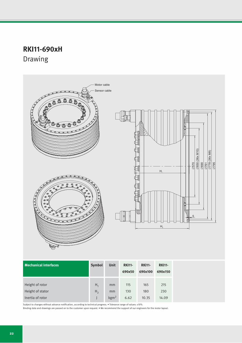
RKI11-690xHDrawing
H2
5
57
0
650
(36x
M10
)
690
76
1
778
(36x
M8)
79
5
H1
Motor cable
Sensor cable
Mechanical interfaces Symbol Unit
Height of rotor H1 mm
Height of stator H2 mm
Inertia of rotor J kgm2
RKI11-
690x50
115
130
6.62
RKI11-
690x100
165
180
10.35
RKI11-
690x150
215
230
14.09
Subjecttochangeswithoutadvancenotification,accordingtotechnicalprogress.•Tolerancerangeofvalues:±10%
Binding data and drawings are passed on to the customer upon request.•We recommend the support of our engineers for the motor layout.

23
RKI11-690xHTechnical data (dimensioning examples)
Technical data Symbol Unit RKI11- RKI11- RKI11- RKI11- RKI11- RKI11-
690x50 690x50 690x100 690x100 690x150 690x150
(High torque) (High speed) (High torque) (High speed) (High torque) (High speed)
Number of pole pairs P
Ultimatetorque (1 s) at Iu Tu Nm
Max. peak torque (saturation range) Tp Nm
Max. continuous torque (up to n1 - cooled) Tcw1 Nm
Max. continuous torque (up to n2 - cooled) Tcw2 Nm
Torque at nmax (cooled) T3 Nm
Max. stall torque (cooled) Tsw Nm
Ripple torque (cogging, reluctance torque) Tr Nm
Power loss (copper) at Tp (130 °C) Plp W
Power loss (copper) at Tcw1 (120 °C) Plw W
Motor constant (25 °C) km Nm/√W
Electrical time constant te ms
Water flow (cooling) dV/dt l/min
Water temperature difference (cooling) ∆ϑ K
Max.DClinkvoltage UDCL-max VDC
Max. continuous current (speed dependent) Icw Arms
Dynamic specific values (thermally conditioned)
Limiting speed for Tcw1 n1 rpm
Limiting speed for Tcw2 n2 rpm
Max. speed for Pcont = constant nmax rpm
Max. continuous power output Pcont kW (in field weakening)
55
4361
3738
1900
1425
713
1349
11.2
19715
3286
42.00
8.6
13.4
3.5
650
175.0
55
218
436
32.6
55
3568
3092
1512
1134
464
1073
9.3
19715
3286
33.41
8.6
13.4
3.5
650
175.0
55
245
600
29.1
55
8722
7476
4265
3199
1600
3028
22.4
31313
6571
66.65
10.8
26.8
3.5
650
175.0
55
218
436
73.1
55
7136
6185
3392
2544
1041
2409
18.6
31313
6571
53.02
10.8
26.8
3.5
650
175.0
55
245
600
65.4
55
13083
11214
6693
5020
2511
4752
33.6
42910
9857
85.40
11.8
40.2
3.5
650
175.0
55
218
436
114.7
55
10704
9277
5324
3993
1634
3780
27.8
42910
9857
67.93
11.8
40.2
3.5
650
175.0
55
245
600
102.6
Subjecttochangeswithoutadvancenotification,accordingtotechnicalprogress.•Tolerancerangeofvalues:±10%
Binding data and drawings are passed on to the customer upon request.•We recommend the support of our engineers for the motor layout.

24
RKI11-920xHDrawing
H2
5
87
0
890
(48x
M12
)
920
99
1
1010
(48x
M10
)
1030
H1
Motor cable
Sensor cable
Mechanical interfaces Symbol Unit
Height of rotor H1 mm
Height of stator H2 mm
Inertia of rotor J kgm2
RKI11-
920x50
127
130
20.48
RKI11-
920x100
177
180
32.58
RKI11-
920x150
227
230
44.68
Subjecttochangeswithoutadvancenotification,accordingtotechnicalprogress.•Tolerancerangeofvalues:±10%
Binding data and drawings are passed on to the customer upon request.•We recommend the support of our engineers for the motor layout.
25
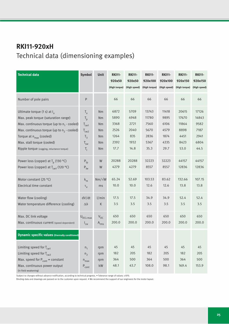
RKI11-920xHTechnical data (dimensioning examples)
Technical data Symbol Unit RKI11- RKI11- RKI11- RKI11- RKI11- RKI11-
920x50 920x50 920x100 920x100 920x150 920x150
(High torque) (High speed) (High torque) (High speed) (High torque) (High speed)
Number of pole pairs P
Ultimatetorque (1 s) at Iu Tu Nm
Max. peak torque (saturation range) Tp Nm
Max. continuous torque (up to n1 - cooled) Tcw1 Nm
Max. continuous torque (up to n2 - cooled) Tcw2 Nm
Torque at nmax (cooled) T3 Nm
Max. stall torque (cooled) Tsw Nm
Ripple torque (cogging, reluctance torque) Tr Nm
Power loss (copper) at Tp (130 °C) Plp W
Power loss (copper) at Tcw1 (120 °C) Plw W
Motor constant (25 °C) km Nm/√W
Electrical time constant te ms
Water flow (cooling) dV/dt l/min
Water temperature difference (cooling) ∆ϑ K
Max.DClinkvoltage UDCL-max VDC
Max. continuous current (speed dependent) Icw Arms
Dynamic specific values (thermally conditioned)
Limiting speed for Tcw1 n1 rpm
Limiting speed for Tcw2 n2 rpm
Max. speed for Pcont = constant nmax rpm
Max. continuous power output Pcont kW (in field weakening)
66
6872
5890
3368
2526
1264
2392
17.7
20288
4279
65.24
10.0
17.5
3.5
650
200.0
45
182
364
48.1
66
5709
4948
2721
2040
835
1932
14.8
20288
4279
52.69
10.0
17.5
3.5
650
200.0
45
205
500
43.7
66
13743
11780
7560
5670
2836
5367
35.3
32223
8557
103.53
12.6
34.9
3.5
650
200.0
45
182
364
108.0
66
11418
9895
6106
4579
1874
4335
29.7
32223
8557
83.62
12.6
34.9
3.5
650
200.0
45
205
500
98.1
66
20615
17670
11864
8898
4451
8423
53.0
44157
12836
132.66
13.8
52.4
3.5
650
200.0
45
182
364
169.4
66
17126
14843
9582
7187
2941
6804
44.5
44157
12836
107.15
13.8
52.4
3.5
650
200.0
45
205
500
153.9
Subjecttochangeswithoutadvancenotification,accordingtotechnicalprogress.•Tolerancerangeofvalues:±10%
Binding data and drawings are passed on to the customer upon request.•We recommend the support of our engineers for the motor layout.

26
Checklist for Your [email protected] or Fax +49 3681 7574-30
Predominant operating mode
Continuous operation Intermittent operation
(S1, e.g. in NC axes) (S6, e.g. in cycled applications)
Operating several motors in parallel
No Yes
Tandem arrangement Janus arrangement
Motor type (if known)
Any required compatibility to Manufacturer Type
Installation space Min. internal diameter / max. external diameter / max. height in mm
/ /
Required operating points
Operating point 1
Torque Speed
Continuous operation (S1) Intermittent operation (S6) Standstill
Operating point 2
Torque Speed
Continuous operation (S1) Intermittent operation (S6) Standstill
Frequency converter Manufacturer Type
DC link voltage [VDC] Constant operation current (S1) Peak current
Company Contact Sector/project designation
Telephone E-mail
Application
Rotary table Swivel application Other
Cooling
Water cooling (standard) Convection Other
Cable
Cable outlet
Axial (standard) Tangential Radial
Cable type Cable length
Separate motor and sensor cables 1 m standard, open-ended Other types and lengths upon request.
O-rings (seals required for water cooled motors)
Yes No
Temperature sensors
PTC and PT1000 (standard) Others upon request.
Technical documentation
Paper CD Language
General information
Single item Series Prototype for series
Estimated annual quantity required Planned series start Price range/cost of previous solution
Desired date of quotation
Further processing by: Date:
Created by: Date:
Feasibility checked by: Date:
Please fill out the following checklist so that we can respond to your enquiry quickly and precisely.
Please feel free to contact the IDAM sales team if you have any questions.

27
Checklist for Your [email protected] or Fax +49 3681 7574-30
Predominant operating mode
Continuous operation Intermittent operation
(S1, e.g. in NC axes) (S6, e.g. in cycled applications)
Operating several motors in parallel
No Yes
Tandem arrangement Janus arrangement
Motor type (if known)
Any required compatibility to Manufacturer Type
Installation space Min. internal diameter / max. external diameter / max. height in mm
/ /
Required operating points
Operating point 1
Torque Speed
Continuous operation (S1) Intermittent operation (S6) Standstill
Operating point 2
Torque Speed
Continuous operation (S1) Intermittent operation (S6) Standstill
Frequency converter Manufacturer Type
DC link voltage [VDC] Constant operation current (S1) Peak current
Company Contact Sector/project designation
Telephone E-mail
Application
Rotary table Swivel application Other
Cooling
Water cooling (standard) Convection Other
Cable
Cable outlet
Axial (standard) Tangential Radial
Cable type Cable length
Separate motor and sensor cables 1 m standard, open-ended Other types and lengths upon request.
O-rings (seals required for water cooled motors)
Yes No
Temperature sensors
PTC and PT1000 (standard) Others upon request.
Technical documentation
Paper CD Language
General information
Single item Series Prototype for series
Estimated annual quantity required Planned series start Price range/cost of previous solution
Desired date of quotation
Further processing by: Date:
Created by: Date:
Feasibility checked by: Date:
Please fill out the following checklist so that we can respond to your enquiry quickly and precisely.
Please feel free to contact the IDAM sales team if you have any questions.

28
Combined turning/milling machines
(universals) should have a wide range
of torque for the milling process and
a wide range of speed for the turning
process.
Current torque motors (standards) often
cannot fulfill this requirement simply
caused by performance limits.
The RKI motor technology enables
reaching such high torque requirements
as well as high speed requirements up
to 3000 rpm.
Moreover it’s important to consider the
whole system view especially the inter-
action of motor and bearing.
We gladly give advice to select suitable
components.
The fastest rotary axis
Through the combination of axial angular contact ball bearings ZKLDF of
Generation B with torque motors RKI, rotary axes using standard components
can be achieved with previously unattainable performance characteristics.
In this way, these products make a decisive contribution to increasing the
productivity of machine tools.
RKI Torque Motors for Turning/Milling Applications

29
Technical Information and Consulting Services
Class leading technology and competent
consulting services are two of the major
benefits of working with IDAM.
IDAM application engineers are looking
forward to support you choose the per-
fect drive for your application.
Get in contact with us.
Phone: +49 3681 7574-0
Automation/medical engineering
E-mail: idam.automation@schaeffler.
com
Productronics/measuring technology
E-mail: idam.productronic@schaeffler.
com
Production machinery/heavy industries
E-mail: [email protected]
Automotive
E-mail: idam.automotive@schaeffler.
com
INA/FAG bearings by Schaeffler for the
production machinery
E-mail:
Web:
www.schaeffler.com/machine-tools
TPI 120: High Precision
Bearings for Combined
Loads

30
IDAM Worldwide
AustriaPhone: +43 2672 2023201E-mail: [email protected]
CanadaPhone: +780 980 3016E-mail: [email protected]
ChinaPhone: +86 21 39576942E-mail: [email protected]
FinlandPhone: +358 207 366204E-mail: [email protected]
IsraelPhone: +972 4 8114146E-mail: [email protected]
ItalyPhone: +39 0321 929267 E-mail: [email protected]
JapanPhone: +81 45 2879412E-mail: [email protected]
KoreaPhone: +82 2 311 3440E-mail: [email protected]
NetherlandsPhone: +31 342 403208 E-mail: [email protected]
RussiaPhone: +7 495 7377660E-mail: [email protected]
Singapore/MalaysiaPhone: +65 6549 6860E-mail: [email protected]
Spain/PortugalPhone: +34 93 4803675E-mail: [email protected]
SwitzerlandPhone: +41 71 4666471E-mail: [email protected]
TaiwanE-mail: [email protected]
United KingdomE-mail: [email protected]
USAPhone: +1 803 5488500E-mail: [email protected]
Other countriesE-mail: [email protected]

31
Overview of Publications
Are you interested in detailed technical information?
We would be happy to send you our product brochures. Contact us: [email protected]
1
RDDM
Rotary Direct Drive Motors
RIB Series
RDDM – Rotary Direct
Drive Motors: RIB Series
We would be happy to provide you with
product brochures for our electronic
assemblies and system solutions.
All information about our motors and
systems can also be found on our
website at www.idam.de.
LDDM
Linear Direct Drive Motors
L1 Series
1
RDDM
Rotary Direct Drive Motors
LDDM
Linear Direct Drive Motors
L2U Series
Torque Motors
RKI Series
1
RDDS
Rotary Direct Drive Systems
RDDS1 Matrix
RDDS2 Matrix
1
X/Y Positioning Systems
based on
Planar Motor Technology
1
IDAM Direct Drives
The perfect solution for every application
anywhere in the world.
Togetherwe move
theworld.
LDDM – Linear Direct
Drive Motors: L1 Series
RDDM – Rotary Direct
Drive Motors:
RI/RE Series
LDDM – Linear Direct
Drive Motors: L2USeries
Torque Motors:
RKI Series
LDDM – Linear Direct
DriveMotors:UPLSeries
RDDS – Rotary Direct
Drive Systems: RDDS1,
RDDS2 Matrix
X/Y Positioning Systems
based on Planar Motor
Technology
Product Overview:
IDAM Direct Drives
1
LDDM
Linear Direct Drive Motors
UPL Series
Issue: August 2016 I Subject to changes without advance notification, according to technical progress.
Photos: IDAM AG & Co. KG, Schaeffler Technologies AG & Co. KG
INA – Drives & Mechatronics AG & Co. KG
Mittelbergstrasse 2
98527 Suhl, Germany
Phone +49 3681 I 7574-0
Fax +49 3681 I 7574-30
E-mail [email protected]
Web www.idam.de