Embed Size (px)
Citation preview
XL Lawn Tractor Service Manual 5 - 1
ELECTRICAL SYSTEM
Electrical SystemThe electrical systems in all the XL Lawn Tractors are similar when starting the tractor. Two things happen when turning the ignition switch to the “START” position. (1) Current will flow from the ignition switch through the PTO (Power Take Off) switch, the clutch/brake switch and to the coil of the starter solenoid. The solenoid is actuated by the coil, connecting the starter motor to the battery. To have this circuit completed, the mower deck must be disengaged (PTO switch) and the clutch/brake pedal must be depressed. (2) At the same time, with the ignition switch in the “START” position, current will flow to the relay, which activates and takes the engine magneto ground wire off of ground to allow the engine to have spark.
Once you have the tractor running, you can now engage the mower deck only if you are in the seat, activating the seat switch. Anytime you vacate the seat with the mower engaged (or the brake pedal released), the seat switch will open and cut off voltage to the relay, which will deactivate and ground the engine magneto and stop the engine. If you vacate the seat with the PTO disengaged and the park brake engaged, the engine will continue to run.
The following electrical section covers most of the electrical components used on the XL Lawn Tractors. It covers each electrical component’s purpose, how it works, testing procedures, and location on the tractor. To help you further to troubleshoot electrical problems, the Riding Products Electrical Demystification Guide, Form # 492-4509, is available with complete wiring and circuit diagrams to help diagnose electrical problems.
RelayPurpose
The relay (or kill relay) is in the safety circuit and the Key Choice™ Reverse Operating System. When applying current to this relay, it will keep the engine magneto wire off of ground, which will allow the engine to run. When the safety circuit or the Reverse Operating System interrupts the current to the relay, the engine magneto wire will ground and stop the engine.
Location
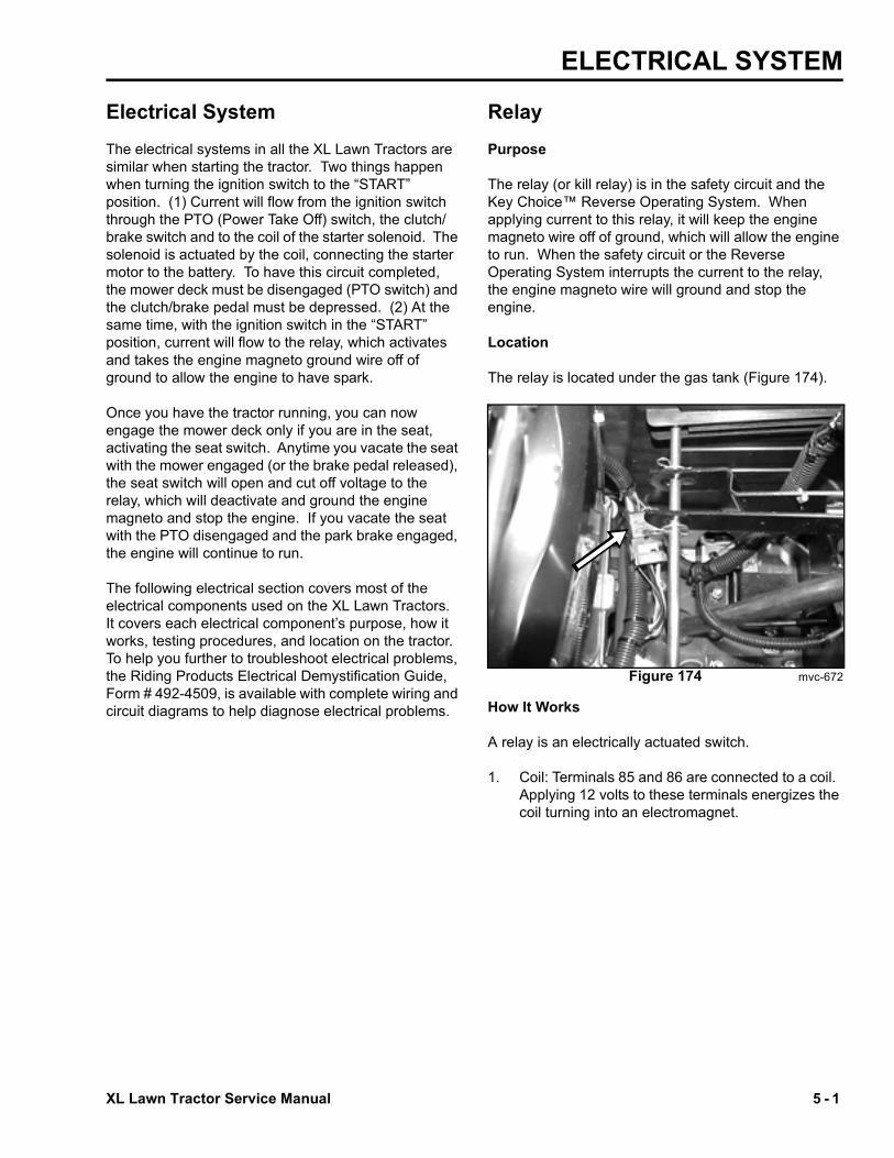
The relay is located under the gas tank (Figure 174).
Figure 174 mvc-672
How It Works
A relay is an electrically actuated switch.
1. Coil: Terminals 85 and 86 are connected to a coil. Applying 12 volts to these terminals energizes the coil turning into an electromagnet.

ELECTRICAL SYSTEM
5 - 2 XL Lawn Tractor Service Manual
2. Switch: Terminals 30, 87, and 87a are actually part of a single pole, double throw (SPDT) switch. Terminal 30 is the common lead. The switch is spring loaded so that 30 and 87a are connected when the coil is not energized. When the coil is energized, the switch is “thrown” and 30 and 87 are connected (Figure 175).
Figure 175 mvc-671
Testing
1. Disconnect the relay from the harness.
2. Verify the coil resistance between terminals 85 and 86 with a multimeter (ohms setting). Resistance should be from 80 to 90 ohms. There should be continuity between terminals 87a and 30.
3. Connect multimeter (ohms setting) leads to relay terminals 30 and 87. Ground terminal 86 and apply +12 VDC to terminal 85. The relay should make and break continuity between terminals 30 and 87 as 12 VDC is applied and removed from terminal 85.
4. Connect multimeter (ohms setting) leads to relay terminals 30 and 87a. Apply +12 VDC to terminal 85. With terminal 86 still grounded, the relay should break and make continuity between terminals 30 and 87a as 12 VDC is applied and removed from terminal.
5. Disconnect voltage and multimeter leads from relay terminals.
Figure 176
SolenoidPurpose
The solenoid’s purpose is simply to connect the battery to the starter motor when the ignition switch is turned to Start. The solenoid is used to protect the ignition switch from the high current drawn by the starter motor.
Coil Terminals30 + 87
Terminals30 + 87a
Not Energized Open Closed
Energized Closed Open

XL Lawn Tractor Service Manual 5 - 3
ELECTRICAL SYSTEMHow It Works
The solenoid has two primary parts. One is a coil of wire wrapped around an iron core. Whenever 12 volts is applied to the coil, it becomes a magnet. The other part is a bar type switch. Because it has a large contact area with the contact terminals it can easily handle the high current loads required by the starter motor.
When 12 volts is applied to the coil, it becomes an electromagnet. This quickly pulls the bar toward the contacts and closes the switch. When power is removed from the coil, the spring loaded bar returns to its “normally open” position. The solenoid closes and opens the switch very quickly. This minimizes the “arcing” that can damage other type switches.
The ignition switch is protected because only a small amount of current is needed to activate the coil.
Figure 177
Testing
1. Disconnect the solenoid from the wiring harness.
2. With a multimeter (ohms setting), check to ensure that terminals “c” and “d” are open (no continuity).
3. Apply +12 VDC to terminal “a” and ground terminal “b”. Terminals “c” and “d” should now be closed (continuity).
4. You should be able to hear the solenoid switch “click” when you make the connection.
Figure 178 mvc-675
Location
The solenoid is located under the gas tank (Figure 179).
Figure 179 mvc-676
(1) 1999 & prior models (2) 2000 & later models
(a) & (b) Coil Terminals (c) & (d) Contact Terminals
a b
c d
a
b
c d
1 2

ELECTRICAL SYSTEM
5 - 4 XL Lawn Tractor Service Manual
Neutral Switch (Used on 1999 and Prior Lawn Tractors)Purpose
Used to ensure the transmission is in neutral when starting the unit. It is actuated when the clutch/brake pedal is depressed.
Location
The neutral switch is under the tractor, in the channel of the frame, under the clutch/brake pedal (Figure 180).
Figure 180 mvc-268
How It Works
This SPDT micro switch has three terminals. The lever is spring loaded in the “up” position. When the button is pushed down, continuity switches from COM and NC to COM and NO.
Testing
1. Disconnect the switch from the harness.
2. Verify the conditions from the table.
Figure 181 mvc-677
PTO SwitchPurpose
Used as part of the safety interlock circuit, it is typically used to monitor the position of the PTO lever.
Button ConditionUp Com + NC
Down Com + NO

XL Lawn Tractor Service Manual 5 - 5
ELECTRICAL SYSTEMLocation
The PTO switch is located under the gas tank, inside of the steering tower, below the PTO lever (Figure 182).
Figure 182 mvc-679
How It Works
Operates the same as the Neutral Switch (used on 1999 and prior model lawn tractors).
Testing
Follow the same procedure as the Neutral Switch (used on 1999 and prior lawn tractors) (Figure 183).
Figure 183 mvc-677
Neutral Switch (Used on 2000 and Later Lawn Tractors)Purpose
Used to ensure the transmission is in neutral when starting the unit. It is activated when the clutch/brake pedal is depressed.
Location
Under the tractor, in the channel of the frame, under the clutch/brake pedal (Figure 184).
Figure 184 mvc-681
ELECTRICAL SYSTEM
5 - 6 XL Lawn Tractor Service Manual
How It Works
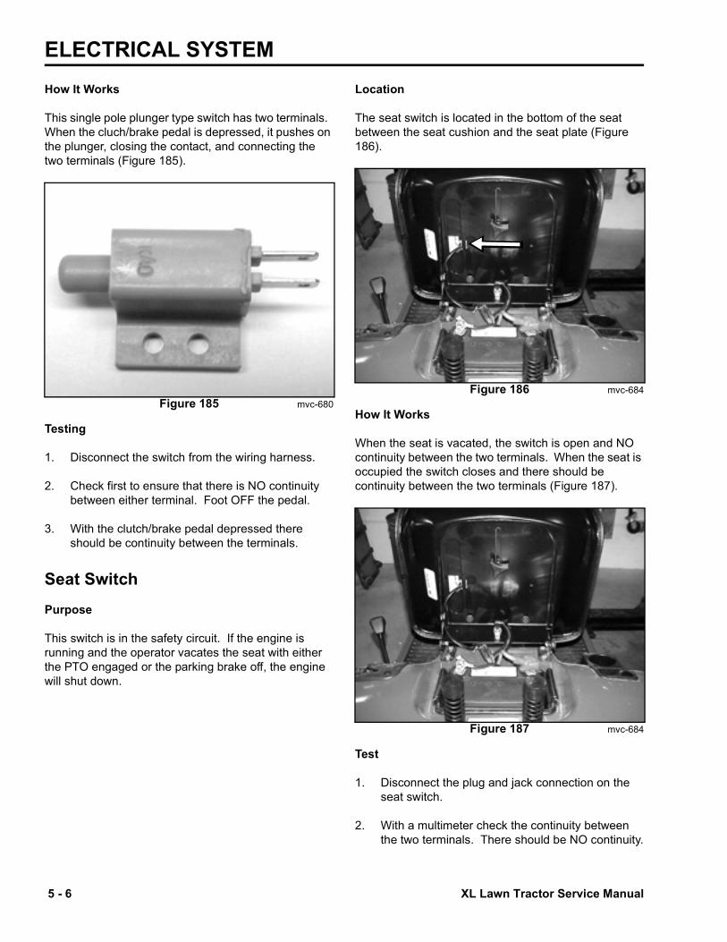
This single pole plunger type switch has two terminals. When the cluch/brake pedal is depressed, it pushes on the plunger, closing the contact, and connecting the two terminals (Figure 185).
Figure 185 mvc-680
Testing
1. Disconnect the switch from the wiring harness.
2. Check first to ensure that there is NO continuity between either terminal. Foot OFF the pedal.
3. With the clutch/brake pedal depressed there should be continuity between the terminals.
Seat SwitchPurpose
This switch is in the safety circuit. If the engine is running and the operator vacates the seat with either the PTO engaged or the parking brake off, the engine will shut down.
Location
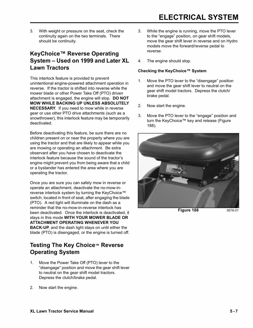
The seat switch is located in the bottom of the seat between the seat cushion and the seat plate (Figure 186).
Figure 186 mvc-684
How It Works
When the seat is vacated, the switch is open and NO continuity between the two terminals. When the seat is occupied the switch closes and there should be continuity between the two terminals (Figure 187).
Figure 187 mvc-684
Test
1. Disconnect the plug and jack connection on the seat switch.
2. With a multimeter check the continuity between the two terminals. There should be NO continuity.
XL Lawn Tractor Service Manual 5 - 7
ELECTRICAL SYSTEM3. With weight or pressure on the seat, check the
continuity again on the two terminals. There should be continuity.
KeyChoice™ Reverse Operating System – Used on 1999 and Later XL Lawn TractorsThis interlock feature is provided to prevent unintentional engine-powered attachment operation in reverse. If the tractor is shifted into reverse while the mower blade or other Power Take Off (PTO) driven attachment is engaged, the engine will stop. DO NOT MOW WHILE BACKING UP UNLESS ABSOLUTELY NECESSARY. If you need to mow while in reverse gear or use other PTO drive attachments (such as a snowthrower), this interlock feature may be temporarily deactivated.
Before deactivating this feature, be sure there are no children present on or near the property where you are using the tractor and that are likely to appear while you are mowing or operating an attachment. Be extra observant after you have chosen to deactivate the interlock feature because the sound of the tractor’s engine might prevent you from being aware that a child or a bystander has entered the area where you are operating the tractor.
Once you are sure you can safely mow in reverse or operate an attachment, deactivate the no-mow-in-reverse interlock system by turning the KeyChoice™ switch, located in front of seat, after engaging the blade (PTO). A red light will illuminate on the dash as a reminder that the no-mow-in-reverse interlock has been deactivated. Once the interlock is deactivated, it stays in this mode WITH YOUR MOWER BLADE OR ATTACHMENT OPERATING WHENEVER YOU BACK-UP, and the dash light stays on until either the blade (PTO) is disengaged, or the engine is turned off.
Testing The Key Choice™ Reverse Operating System1. Move the Power Take Off (PTO) lever to the
“disengage” position and move the gear shift lever to neutral on the gear shift model tractors. Depress the clutch/brake pedal.
2. Now start the engine.
3. While the engine is running, move the PTO lever to the “engage” position, on gear shift models, move the gear shift lever in reverse and on Hydro models move the forward/reverse pedal to reverse.
4. The engine should stop.
Checking the KeyChoice™ System
1. Move the PTO lever to the “disengage” position and move the gear shift lever to neutral on the gear shift model tractors. Depress the clutch/brake pedal.
2. Now start the engine.
3. Move the PTO lever to the “engage” position and turn the KeyChoice™ key and release (Figure 188).
Figure 188 3678-01

ELECTRICAL SYSTEM
5 - 8 XL Lawn Tractor Service Manual
4. A red light on the front console turns on, indicating that the interlock (No-Mow-In-Reverse) is disabled (Figure 189).
Figure 189 3678-03
5. You should be able to operate the machine in reverse and the engine/mower will continue to run.
6. Move the PTO lever to the “disengage” position and the red light should turn off on the front console.
KeyChoice™ Reverse Operating System Switch Purpose
This switch is used in the Key Choice™ Reverse Operating System circuit. When turned to the on position, it allows the operator to mow in reverse.
How It Works
The switch is basically an on/off switch spring-loaded to return to the off position. When turned to the On position with the PTO engaged, it activates circuits in the Key Choice™ Reverse Operating System reverse module and allows the operator to mow in reverse (Figure 190).
Figure 190 mvc-691
Testing
1. Disconnect the switch from the circuit.
2. With a multimeter, check the continuity across the two terminals.
3. Turn the key to the on position and hold, since the switch is spring loaded. There should be continuity across the two terminals.
Reverse SwitchPurpose
This switch works in the Key Choice™ Reverse Operating System circuit when the mower (PTO) is engaged.

XL Lawn Tractor Service Manual 5 - 9
ELECTRICAL SYSTEMLocation
The switch is located under the tractor, near the traction idler (Figure 191).
Figure 191 mvc-686
How It Works
This single pole plunger type switch has two terminals. When the unit is shifted in reverse while the mower blade (PTO engagement lever) is engaged, the reverse switch opens and will stop the engine, unless the KeyChoice switch has been operated.
Testing
1. Disconnect the switch from the wiring circuit.
2. With a multimeter, check the continuity across the terminals. There should be continuity.
3. Depress the plunger on the switch and check the continuity across the terminals, there should be NO continuity (Figure 192).
Figure 192 mvc-685
KeyChoice™ Reverse Operating System ModulePurpose
The Key Choice™ Reverse Operating System module works with the KeyChoice™ switch, PTO switch, and the reverse switch. It responds to the reverse switch; if the override switch (KeyChoice™ switch) is not activated and the PTO is engaged, it will stop the engine (Figure 193).
Figure 193 mvc-692

ELECTRICAL SYSTEM
5 - 10 XL Lawn Tractor Service Manual
Location
The Key Choice™ Reverse Operating System module is located under the gas tank (Figure 194).
Figure 194 mvc-694
How it Works
The Key Choice™ Reverse Operating System is made up of several components, such as diodes and relays. When it is connected in the circuit, voltage is applied to certain terminals of the Key Choice™ Reverse Operating System module from the PTO switch, reverse switch, and the override switch, which energizes certain relays in the module. If voltage is not applied to the proper terminals on the Key Choice™ Reverse Operating System module, the engine will stop.
Testing
The Key Choice™ Reverse Operating System module must be removed from the circuit. Using a multimeter check the following:
* NOTE: If multimeter does not have a diode scale, this test can not be done. This is not a problem if powered tests are done. Powered test must be done to check out relays (Figure 195).
Figure 195
Powered circuit test ( with module out of circuit). A 12 volt battery is needed for this test. NOTE: USE CAUTION WHEN MEASURING RESISTANCE WITH A POWERED CIRCUIT. CONTACTING A VOLTAGE SOURCE WITH METER IN OHMS POSITION CAN SERIOUSLY DAMAGE THE METER.
** NOTE: Actual reading should be same as B+ applied to Pin 2.
Meter Scale
Meter Probe
Negative
Meter Probe
PositiveMeter Reading
Ohms Pin 3 Pin 1 Open (more than 100k ohm)
Ohms Pin 3 Pin 2 350 to 450 ohmsDiode Pin 3 Pin 4 0.7V to 1.0V *Diode Pin 3 Pin 5 0.7V to 1.0V *Ohms Pin 3 Pin 6 Open (more than
100k ohms)
Ground B+ (12V)
Meter Probe Neg.
Meter Probe Pos.
Meter Scale
Meter Reading
Pin 3 Pin 4 Pin 3 Pin 1 Ohms <2 ohmsPin 3 Pin 5 Pin 3 Pin 1 Ohms <2 ohmsPin 3 Pin 2 Pin 3 Pin 1 Ohms <2 ohmsPin 3 Pin 2 Pin 3 Pin 6 Volts 12 V **

ELECTRICAL SYSTEM
A5-1XL Lawn Tractor Service Manual
Purpose
The PTO (Power Take Off) switch is typically used to turn on the Electric PTO Clutch and to function as part of the safety interlock system.
The PTO switch is located on the steering tower, below the steering wheel (Fig. A5 001).
Fig A5 001 PICT-4439 Fig A5 002 PTO switch test a
Cont.
OFF (IN) ON (OUT)
Cont.
Open
Open
Cont.
Cont.
Open
Open
1. Disengage the PTO, set the parking brake, turn the ignition to the “OFF” position and remove the key.
2. Remove the gas tank from the steering tower.
3. Disconnect the wiring harness from the PTO switch.
4. Press in on the locking tabs, on each side of the switch, and pull the switch out of the steering tower.
5. Verify that there is continuity between the appropriate terminals in the ON and OFF positions (Fig. A5 002).
When the PTO switch is pulled to the “ON” position, contacts inside the switch electrically connects various terminals. One terminal is connected to the wire that goes directly to the electric clutch. When the PTO is pulled out to the “ON” position, current fl ows to the electric clutch and it engages.
Electric PTO Switch
Location
How It Works
Testing
6. Replace the switch if your test results do not correspond with those given in Fig. A5 002.
7. Mount the PTO switch back into the steering tower, reinstall the wiring harness, and install the gas tank.

ELECTRICAL SYSTEM
A5-2 XL Lawn Tractor Service Manual
Fig A5 003 PICT-4476
Fig A5 004 fi g. 88
The electric clutch is located on the PTO end of the engine crankshaft (Fig. A5 003). 1. Disengage the PTO, set the parking brake, turn the
ignition to OFF, and remove the key.
2. Disconnect the clutch wire connector.
3. Set the multimeter or volt/ohm meter to check resistance (ohms).
4. Connect the meter lead wires to the wires in the clutch connector (Fig. A5 004).
If the electric PTO clutch is not engaging or is suspected as a cause of electrical problems, use the following troubleshooting steps. These procedures will help you determine if the clutch has failed or is the cause of the electrical problem.
Testing
This clutch electrically controls the engagement and disengagement of the Power Take Off (PTO) pulley.
Purpose
Electric PTO Clutch
Location
The PTO clutch is composed of three major components; the fi eld, the clutch plate, and the friction plate. The clutch plate always turns with the engine. The fi eld is a coil of wire on an iron core, which becomes an electromagnet when power is applied.
The friction plate is the only piece that can slide up and down on the crankshaft axis. It is normally spring loaded so that it is not in contact with the clutch plate and is pressed against the brake material opposite the clutch. When power is applied, the friction plate is drawn toward the clutch plate and the two rotate as one.
How It Works
Coil Resistance Measurement
5. The meter should read 2.84 ohms + 0.14 ohms. If the reading is above or below these readings, the fi eld has failed and needs to be replaced. If the reading is between these two limits, measure the clutch current draw.

ELECTRICAL SYSTEM
A5-3XL Lawn Tractor Service Manual
Measuring Clutch Current Draw
1. Disengage the PTO, set the parking brake, turn the ignition key to OFF, and remove the key.
2. Disconnect the clutch wire connector.
3. Set the multimeter to check amps (10 amp scale).
4. Connect the positive meter lead to the tractor terminal (1) of the clutch wire (Fig. A5 005).
Fig A5 005 fi g. 89
5. Connect the negative meter lead to the correspond-ing wire terminal (3) (Fig. A5 005).
6. Connect a short jumper lead from terminal (2) to terminal (4) (Fig. A5 005).
7. Turn the ignition key in the switch to the “RUN” position and the PTO switch to the “ON” position.
8. If the meter is 4.23 amps or above, the system is functioning properly. If the meter reading is below 4.23 amps, check the electrical system for problems.