Embed Size (px)
Citation preview

4.0.1.1 Chapter 4: Network Access
To support our communication, the OSI model divides the functions of a data network into layers. Each layer works with the layers above and below to transmit data.

4.0.1.2 Class Activity – Managing the Medium
Class Activity – Managing the Medium

4.1.1.1 Types of Connections
Whether connecting to a local
printer in the home or a web site in
another country, before any network
communications can occur, a
physical connection to a local
network must be established. A
physical connection can be a wired
connection using a cable or a
wireless connection using radio
waves.

4.1.1.2 Network Interface Cards
Network Interface Cards (NICs)
connect a device to the
network. Ethernet NICs are
used for a wired connection, as
shown in Figure 1, whereas
WLAN (Wireless Local Area
Network) NICs are used for
wireless. An end-user device
may include one or both types
of NICs. A network printer, for
example, may only have an
Ethernet NIC, and therefore,
must connect to the network
using an Ethernet cable. Other
devices, such as tablets and
smartphones, might only
contain a WLAN NIC and must
use a wireless connection.

4.1.1.2 Network Interface Cards
All wireless devices must share
access to the airwaves
connecting to the wireless
access point. This means
slower network performance
may occur as more wireless
devices access the network
simultaneously. A wired device
does not need to share its
access to the network with
other devices. Each wired
device has a separate
communications channel over
its Ethernet cable. This is
important when considering
some applications, such as
online gaming, streaming
video, and video conferencing,
which require more dedicated
bandwidth than other
applications.

4.1.2.1 The Physical Layer
The process that data undergoes from a
source node to a destination node is:
The user data is segmented by the
transport layer, placed into packets by
the network layer, and further
encapsulated into frames by the data
link layer.
The physical layer encodes the
frames and creates the electrical,
optical, or radio wave signals that
represent the bits in each frame.
These signals are then sent on the
media, one at a time.
The destination node physical layer
retrieves these individual signals from
the media, restores them to their bit
representations, and passes the bits
up to the data link layer as a complete
frame.

4.1.2.2 Physical Layer Media
There are three basic forms of
network media. The physical layer
produces the representation and
groupings of bits for each type of
media as:
Copper cable: The signals are
patterns of electrical pulses.
Fiber-optic cable: The signals
are patterns of light.
Wireless: The signals are
patterns of microwave
transmissions.

4.1.2.3 Physical Layer Standards
Physical Layer Standards
The protocols and operations of
the upper OSI layers are
performed in software designed
by software engineers and
computer scientists. The services
and protocols in the TCP/IP suite
are defined by the Internet
Engineering Task Force (IETF).
The physical layer consists of
electronic circuitry, media, and
connectors developed by
engineers. Therefore, it is
appropriate that the standards
governing this hardware are
defined by the relevant electrical
and communications engineering
organizations

4.1.2.4 Lab - Identifying Network Devices and Cabling
In this lab, you will
complete the following
objectives:
Part 1: Identify
Network Devices
Part 2: Identify
Network Media

4.1.3.1 Functions
Encoding
Encoding or line encoding is a method of
converting a stream of data bits into a
predefined "code”. Codes are groupings of
bits used to provide a predictable pattern
that can be recognized by both the sender
and the receiver. In the case of networking,
encoding is a pattern of voltage or current
used to represent bits; the 0s and 1s.

4.1.3.1 Functions
There are many ways to transmit
signals. A common method to send
data is using modulation
techniques. Modulation is the
process by which the characteristic
of one wave (the signal) modifies
another wave (the carrier).
The nature of the actual signals
representing the bits on the media
will depend on the signaling method
in use.

4.1.3.2 Bandwidth
Different physical media support the transfer of bits at different rates. Data transfer is usually
discussed in terms of bandwidth and throughput.
Bandwidth is the capacity of a medium to carry data. Digital bandwidth measures the amount of
data that can flow from one place to another in a given amount of time. Bandwidth is typically
measured in kilobits per second (kb/s), megabits per second (Mb/s), or gigabits per second (Gb/s).
Bandwidth is sometimes thought of as the speed that bits travel, however this is not accurate. For
example, in both 10Mb/s and 100Mb/s Ethernet, the bits are sent at the speed of electricity. The
difference is the number of bits that are transmitted per second.

4.1.3.3 Throughput
Throughput is the measure of the transfer of bits
across the media over a given period of time.
Due to a number of factors, throughput usually does
not match the specified bandwidth in physical layer
implementations. Many factors influence throughput,
including:
The amount of traffic
The type of traffic
The latency created by the number of network
devices encountered between source and
destination
Latency refers to the amount of time, to include delays, for data to travel from one given point to
another.

4.1.3.4 Types of Physical Media
The physical layer produces the
representation and groupings of
bits as voltages, radio
frequencies, or light pulses.
Various standards organizations
have contributed to the definition
of the physical, electrical, and
mechanical properties of the
media available for different data
communications. These
specifications guarantee that
cables and connectors will
function as anticipated with
different data link layer
implementations.

4.1.3.5 Activity - Physical Layer Terminology

4.2.1.1 Characteristics of Copper Cabling
The timing and voltage values of the
electrical pulses are also susceptible to
interference from two sources:
Electromagnetic interference (EMI) or
radio frequency interference (RFI) -
EMI and RFI signals can distort and
corrupt the data signals being carried by
copper media. Potential sources of EMI
and RFI include radio waves and
electromagnetic devices, such as
fluorescent lights or electric motors as
shown in the figure.
Crosstalk - Crosstalk is a disturbance caused by the electric or magnetic fields of a signal on one wire to the
signal in an adjacent wire. In telephone circuits, crosstalk can result in hearing part of another voice
conversation from an adjacent circuit. Specifically, when an electrical current flows through a wire, it creates a
small, circular magnetic field around the wire, which can be picked up by an adjacent wire.
4.2.1.2 Copper Media

4.2.1.3Unshielded Twisted-Pair Cable

4.2.1.4 Shielded Twisted-Pair Cable
Shielded twisted-pair (STP)
provides better noise
protection than UTP cabling.
However, compared to UTP
cable, STP cable is
significantly more expensive
and difficult to install. Like
UTP cable, STP uses an RJ-
45 connector.

4.2.1.5 Coaxial Cable
Although UTP cable has essentially replaced coaxial cable in modern Ethernet installations, the coaxial cable design is used in:• Wireless installations: Coaxial cables attach antennas to wireless devices. The coaxial cable carries radio frequency (RF) energy between the antennas and the radio equipment. • Cable Internet installations: Cable service providers provide Internet connectivity to their customers by replacing portions of the coaxial cable and supporting amplification elements with fiber-optic cable. However, the wiring inside the customer's premises is still coax cable.

4.2.1.6 Copper Media Safety

4.2.1.7 Activity - Copper Media Characteristics

4.2.2.1 Properties of UTP Cabling
UTP cable does not use shielding to counter the effects of
EMI and RFI. Instead, cable designers have discovered
that they can limit the negative effect of crosstalk by:
Cancellation: Designers now pair wires in a circuit.
When two wires in an electrical circuit are placed close
together, their magnetic fields are the exact opposite of
each other. Therefore, the two magnetic fields cancel
each other and also cancel out any outside EMI and
RFI signals.
Varying the number of twists per wire pair: To
further enhance the cancellation effect of paired circuit
wires, designers vary the number of twists of each wire
pair in a cable. UTP cable must follow precise
specifications governing how many twists or braids are
permitted per meter (3.28 feet) of cable. Notice in the
figure that the orange/orange white pair is twisted less
than the blue/blue white pair. Each colored pair is
twisted a different number of times.

4.2.2.2 UTP Cabling Standards

4.2.2.3 UTP Connectors

4.2.2.3 UTP Connectors

4.2.2.4 Types of UTP Cable
Ethernet Straight-through:
The most common type of
networking cable. It is
commonly used to
interconnect a host to a
switch and a switch to a
router.
Ethernet Crossover: A cable
used to interconnect similar
devices. For example to
connect a switch to a switch,
a host to a host, or a router to
a router.
Rollover: A Cisco proprietary
cable used to connect a
workstation to a router or
switch console port.

4.2.2.5 Testing UTP Cables
After installation, a UTP
cable tester, like the one
shown in the figure, should
be used to test for the
following parameters:
Wire map
Cable length
Signal loss due to
attenuation
Crosstalk

4.2.2.6 Cable Pinouts

4.2.2.7 Lab - Building an Ethernet Crossover Cable

4.2.3.1 Properties of Fiber-Optic Cabling
Fiber-optic cabling is now being used in four types of
industry:
Enterprise Networks: Used for backbone
cabling applications and interconnecting
infrastructure devices.
Fiber-to-the-Home (FTTH): Used to provide
always-on broadband services to homes and
small businesses.
Long-Haul Networks: Used by service providers
to connect countries and cities.
Submarine Networks: Used to provide reliable
high-speed, high-capacity solutions capable of
surviving in harsh undersea environments up to
transoceanic distances. Click here to view a
telegeography map that depicts the location
of submarine cables.

4.2.3.2 Fiber Media Cable Design

4.2.3.3 Types of Fiber Media

4.2.3.4 Fiber-Optic Connectors

4.2.3.4 Fiber-Optic Connectors

4.2.3.4 Fiber-Optic Connectors

4.2.3.5 Testing Fiber Cables
Three common types of fiber-
optic termination and splicing
errors are:
Misalignment: The fiber-optic
media are not precisely
aligned to one another when
joined.
End gap: The media does not
completely touch at the splice
or connection.
End finish: The media ends
are not well polished, or dirt is
present at the termination.

4.2.3.6 Fiber versus Copper

4.2.3.7 Activity - Fiber Optics Terminology

4.2.4.1 Properties of Wireless Media
Wireless does have some areas of concern, including:
Coverage area: Wireless data technologies work well in open
environments. However, certain construction materials used in
buildings and structures, and the local terrain, will limit the effective
coverage.
Interference: Wireless is susceptible to interference and can be
disrupted by such common devices as household cordless phones,
some types of fluorescent lights, microwave ovens, and other
wireless communications.
Security: Devices and users, not authorized for access to the
network, can gain access to the transmission. Network security is a
major component of wireless network administration.
Shared medium: WLANs operate in half-duplex, which means only
one device can send or receive at a time. The wireless medium is
shared amongst all wireless users. The more users needing to
access the WLAN simultaneously, results in less bandwidth for
each user. Half-duplex is discussed later in this chapter.

4.2.4.2 Types of Wireless Media
4.2.4.4 Packet Tracer – Connecting a Wired and Wireless LAN

4.2.4.5 Lab - Viewing Wired and Wireless NIC Information

4.3.1.1 The Data Link Layer
The data link layer of the OSI model (Layer
2), as shown in Figure 1, is responsible for:
Allowing the upper layers to access the
media
Accepting Layer 3 packets and
packaging them into frames
Preparing network data for the physical
network
Controlling how data is placed and
received on the media
Exchanging frames between nodes
over a physical network media, such as
UTP or fiber-optic
Receiving and directing packets to an
upper layer protocol
Performing error detection

4.3.1.1 The Data Link Layer

4.3.1.2 Data Link Sublayers
The data link layer is divided into two
sublayers:
Logical Link Control (LLC) - This
upper sublayer communicates with
the network layer. It places
information in the frame that
identifies which network layer
protocol is being used for the frame.
This information allows multiple
Layer 3 protocols, such as IPv4 and
IPv6, to utilize the same network
interface and media.
Media Access Control (MAC) -
This lower sublayer defines the
media access processes performed
by the hardware. It provides data link
layer addressing and access to
various network technologies.

4.3.1.3 Media Access Control

4.3.1.4 Providing Access to Media
At each hop along the
path, a router:
Accepts a frame from a
medium
De-encapsulates the
frame
Re-encapsulates the
packet into a new frame
Forwards the new
frame appropriate to the
medium of that segment
of the physical network

4.3.1.5 Data Link Layer Standards
Institute of Electrical and
Electronics Engineers
(IEEE)
International
Telecommunication Union
(ITU)
International Organization
for Standardization (ISO)
American National
Standards Institute (ANSI)

4.4.1.1 Controlling Access to the Media
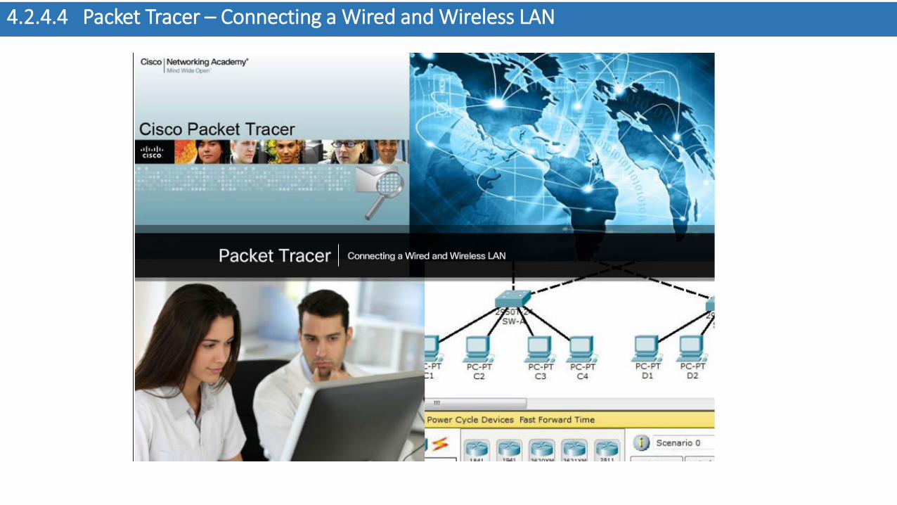
4.4.1.2 Physical and Logical Topologies
Physical topology - Refers to the
physical connections and
identifies how end devices and
infrastructure devices such as
routers, switches, and wireless
access points are interconnected.
Physical topologies are usually
point-to-point or star.

4.4.1.2 Physical and Logical Topologies
Logical topology - Refers
to the way a network
transfers frames from one
node to the next. This
arrangement consists of
virtual connections between
the nodes of a network.
These logical signal paths
are defined by data link
layer protocols. The logical
topology of point-to-point
links is relatively simple
while shared media offers
different access control methods.

4.4.2.1 Common Physical WAN Topologies
WANs are commonly interconnected using the
following physical topologies:
Point-to-Point - This is the simplest
topology that consists of a permanent link
between two endpoints. For this reason, this
is a very popular WAN topology.
Hub and Spoke - A WAN version of the star
topology in which a central site
interconnects branch sites using point-to-
point links.
Mesh - This topology provides high
availability, but requires that every end
system be interconnected to every other
system. Therefore the administrative and
physical costs can be significant. Each link
is essentially a point-to-point link to the
other node. Variations of this topology
include a partial mesh where some but not
all of end devices are interconnected.

4.4.2.2 Physical Point-to-Point Topology

4.4.2.3 Logical Point-to-Point Topology

4.4.3.1 Physical LAN Topologies Topologies
Star - End devices are
connected to a central
intermediate device. The star
topology is easy to install, very
scalable (easy to add and
remove end devices), and easy
to troubleshoot.
Extended Star - In an extended
star topology, additional Ethernet
switches interconnect other star
topologies.
Bus - Infrastructure devices
such as switches are not
required to interconnect the end
devices. Bus topologies using
coax cables were used in legacy
Ethernet networks because it
was inexpensive and easy to set
up.

4.4.3.2 Half and Full Duplex
Half-duplex communication -
Both devices can transmit and
receive on the media but cannot
do so simultaneously. The half-
duplex mode is used in legacy
bus topologies and with Ethernet
hubs. WLANs also operate in
half-duplex. Half-duplex allows
only one device to send or
receive at a time on the shared
medium and is used with
contention-based access
methods. Figure 1 shows half-
duplex communication.

4.4.3.2 Half and Full Duplex
Full-duplex
communication - Both
devices can transmit and
receive on the media at the
same time. The data link
layer assumes that the
media is available for
transmission for both nodes
at any time. Ethernet
switches operate in full-
duplex mode by default, but
can operate in half-duplex if
connecting to a device such
as an Ethernet hub. Figure 2
shows full-duplex
communication.

4.4.3.3 Media Access Control Methods
Contention-based
access - All nodes
operating in half-duplex
compete for the use of
the medium, but only
one device can send at
a time. However, there
is a process if more
than one device
transmits at the same
time. Ethernet LANs
using hubs and WLANs
are examples of this
type of access control.
Figure 1 shows
contention-based
access.

4.4.3.3 Media Access Control Methods
Controlled access - Each node has its
own time to use the medium. These
deterministic types of networks are
inefficient because a device must wait its
turn to access the medium. Legacy Token
Ring LANs are an example of this type of
access control. Figure 2 shows controlled
access. Refer to the Chapter Appendix to
learn more about controlled access.

4.4.3.4 Contention-Based Access – CSMA/CD

4.4.3.5 Contention-Based Access – CSMA/CA
Another form of CSMA that is
used by IEEE 802.11 WLANs is
Carrier Sense Multiple
Access/Collision Avoidance
(CSMA/CA). CMSA/CA uses a
method similar to CSMA/CD to
detect if the media is clear.
CMSA/CA also uses additional
techniques. CMSA/CA does not
detect collisions but attempts to
avoid them by waiting before transmitting
Multiple Access/Collision Avoidance

4.4.4.1 The Frame
The description of a frame is a key element of each data link layer protocol. Although there are many different data link layer protocols that describe data link layer frames, each frame type has three basic parts:•Header•Data•Trailer

4.4.4.2 Frame Fields
Frame start and stop indicator flags -
Used to identify the beginning and end
limits of the frame.
Addressing - Indicates the source and
destination nodes on the media.
Type - Identifies the Layer 3 protocol in
the data field.
Control - Identifies special flow control
services such as quality of service
(QoS). QoS is used to give forwarding
priority to certain types of messages.
Data - Contains the frame payload (i.e.,
packet header, segment header, and
the data).
Error Detection - These frame fields
are used for error detection and are
included after the data to form the
trailer.

4.4.4.3 Activity – Generic Frame Fields
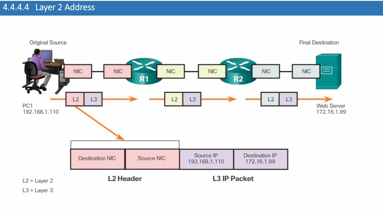
4.4.4.4 Layer 2 Address

4.4.4.5 LAN and WAN Frames
Data link layer protocols
include:
• Ethernet
• 802.11 Wireless
• Point-to-Point Protocol
(PPP)
• HDLC
• Frame Relay

4.5.1.1 Class Activity – Linked In!

4.5.1.2 Chapter 4: Network Access