Embed Size (px)
Citation preview
Preliminary
TMS320x2803x Piccolo Enhanced QuadratureEncoder Pulse (eQEP) Module
Reference Guide
Literature Number: SPRUFK8May 2009

Preliminary
2 SPRUFK8–May 2009Submit Documentation Feedback

Contents
Preface ........................................................................................................................................ 61 Introduction......................................................................................................................... 82 Description ........................................................................................................................ 10
2.1 EQEP Inputs ............................................................................................................. 112.2 Functional Description .................................................................................................. 112.3 eQEP Memory Map ..................................................................................................... 12
3 Quadrature Decoder Unit (QDU) ........................................................................................... 143.1 Position Counter Input Modes ......................................................................................... 143.2 eQEP Input Polarity Selection ......................................................................................... 173.3 Position-Compare Sync Output........................................................................................ 17
4 Position Counter and Control Unit (PCCU) ............................................................................ 174.1 Position Counter Operating Modes.................................................................................... 174.2 Position Counter Latch.................................................................................................. 204.3 Position Counter Initialization .......................................................................................... 224.4 eQEP Position-compare Unit .......................................................................................... 22
5 eQEP Edge Capture Unit ..................................................................................................... 246 eQEP Watchdog ................................................................................................................. 277 Unit Timer Base ................................................................................................................. 278 eQEP Interrupt Structure ..................................................................................................... 289 eQEP Registers .................................................................................................................. 28
SPRUFK8–May 2009 Table of Contents 3Submit Documentation Feedback
Preliminary
www.ti.com
List of Figures1 Optical Encoder Disk ........................................................................................................ 82 QEP Encoder Output Signal for Forward/Reverse Movement......................................................... 93 Index Pulse Example........................................................................................................ 94 Functional Block Diagram of the eQEP Peripheral .................................................................... 125 Functional Block Diagram of Decoder Unit ............................................................................. 146 Quadrature Decoder State Machine ..................................................................................... 157 Quadrature-clock and Direction Decoding .............................................................................. 168 Position Counter Reset by Index Pulse for 1000 Line Encoder (QPOSMAX = 3999 or 0xF9F)................. 189 Position Counter Underflow/Overflow (QPOSMAX = 4) .............................................................. 1910 Software Index Marker for 1000-line Encoder (QEPCTL[IEL] = 1) .................................................. 2111 Strobe Event Latch (QEPCTL[SEL] = 1) ................................................................................ 2112 eQEP Position-compare Unit ............................................................................................. 2213 eQEP Position-compare Event Generation Points..................................................................... 2314 eQEP Position-compare Sync Output Pulse Stretcher................................................................ 2315 eQEP Edge Capture Unit ................................................................................................. 2516 Unit Position Event for Low Speed Measurement (QCAPCTL[UPPS] = 0010) .................................... 2517 eQEP Edge Capture Unit - Timing Details.............................................................................. 2618 eQEP Watchdog Timer .................................................................................................... 2719 eQEP Unit Time Base ..................................................................................................... 2820 EQEP Interrupt Generation ............................................................................................... 2821 QEP Decoder Control (QDECCTL) Register ........................................................................... 2922 eQEP Control (QEPCTL) Register....................................................................................... 3023 eQEP Position-compare Control (QPOSCTL) Register ............................................................... 3124 eQEP Capture Control (QCAPCTL) Register .......................................................................... 3225 eQEP Position Counter (QPOSCNT) Register ......................................................................... 3326 eQEP Position Counter Initialization (QPOSINIT) Register........................................................... 3327 eQEP Maximum Position Count Register (QPOSMAX) Register.................................................... 3328 eQEP Position-compare (QPOSCMP) Register........................................................................ 3329 eQEP Index Position Latch (QPOSILAT) Register .................................................................... 3430 eQEP Strobe Position Latch (QPOSSLAT) Register .................................................................. 3431 eQEP Position Counter Latch (QPOSLAT) Register .................................................................. 3432 eQEP Unit Timer (QUTMR) Register .................................................................................... 3533 eQEP Register Unit Period (QUPRD) Register ........................................................................ 3534 eQEP Watchdog Timer (QWDTMR) Register .......................................................................... 3535 eQEP Watchdog Period (QWDPRD) Register ......................................................................... 3536 eQEP Interrupt Enable (QEINT) Register............................................................................... 3637 eQEP Interrupt Flag (QFLG) Register ................................................................................... 3738 eQEP Interrupt Clear (QCLR) Register.................................................................................. 3839 eQEP Interrupt Force (QFRC) Register ................................................................................. 3940 eQEP Status (QEPSTS) Register........................................................................................ 4041 eQEP Capture Timer (QCTMR) Register ............................................................................... 4142 eQEP Capture Period (QCPRD) Register .............................................................................. 4143 eQEP Capture Timer Latch (QCTMRLAT) Register................................................................... 4144 eQEP Capture Period Latch (QCPRDLAT) Register .................................................................. 42
List of Figures4 SPRUFK8–May 2009Submit Documentation Feedback
Preliminary
www.ti.com
List of Tables1 EQEP Memory Map ....................................................................................................... 122 Quadrature Decoder Truth Table ........................................................................................ 153 eQEP Decoder Control (QDECCTL) Register Field Descriptions ................................................... 294 eQEP Control (QEPCTL) Register Field Descriptions................................................................. 305 eQEP Position-compare Control (QPOSCTL) Register Field Descriptions......................................... 316 eQEP Capture Control (QCAPCTL) Register Field Descriptions .................................................... 327 eQEP Position Counter (QPOSCNT) Register Field Descriptions................................................... 338 eQEP Position Counter Initialization (QPOSINIT) Register Field Descriptions .................................... 339 eQEP Maximum Position Count (QPOSMAX) Register Field Descriptions ........................................ 3310 eQEP Position-compare (QPOSCMP) Register Field Descriptions ................................................. 3411 eQEP Index Position Latch(QPOSILAT) Register Field Descriptions ............................................... 3412 eQEP Strobe Position Latch (QPOSSLAT) Register Field Descriptions............................................ 3413 eQEP Position Counter Latch (QPOSLAT) Register Field Descriptions ............................................ 3414 eQEP Unit Timer (QUTMR) Register Field Descriptions.............................................................. 3515 eQEP Unit Period (QUPRD) Register Field Descriptions ............................................................. 3516 eQEP Watchdog Timer (QWDTMR) Register Field Descriptions.................................................... 3517 eQEP Watchdog Period (QWDPRD) Register Field Description .................................................... 3618 eQEP Interrupt Enable(QEINT) Register Field Descriptions ......................................................... 3619 eQEP Interrupt Flag (QFLG) Register Field Descriptions............................................................. 3720 eQEP Interrupt Clear (QCLR) Register Field Descriptions ........................................................... 3821 eQEP Interrupt Force (QFRC) Register Field Descriptions........................................................... 3922 eQEP Status (QEPSTS) Register Field Descriptions ................................................................. 4023 eQEP Capture Timer (QCTMR) Register Field Descriptions......................................................... 4124 eQEP Capture Period Register (QCPRD) Register Field Descriptions ............................................. 4125 eQEP Capture Timer Latch (QCTMRLAT) Register Field Descriptions ............................................ 4226 eQEP Capture Period Latch (QCPRDLAT) Register Field Descriptions............................................ 42
SPRUFK8–May 2009 List of Tables 5Submit Documentation Feedback
Preliminary
PrefaceSPRUFK8–May 2009
Read This First
This reference guide describes the enhanced quadrature encoder pulse (eQEP) module on the x2803xPiccolo™ device family.
About This ManualThe eQEP module described in this reference guide is a Type 0 eQEP. See the TMS320x28xx, 28xxxDSP Peripheral Reference Guide (SPRU566) for a list of all devices with a module of the same type todetermine the differences between types and for a list of device-specific differences within a type.
Notational ConventionsThis document uses the following conventions.• Hexadecimal numbers are shown with the suffix h or with a leading 0x. For example, the following
number is 40 hexadecimal (decimal 64): 40h or 0x40.• Registers in this document are shown in figures and described in tables.
– Each register figure shows a rectangle divided into fields that represent the fields of the register.Each field is labeled with its bit name, its beginning and ending bit numbers above, and itsread/write properties below. A legend explains the notation used for the properties.
– Reserved bits in a register figure designate a bit that is used for future device expansion.
Related Documentation From Texas InstrumentsThe following books describe the TMS320x2802x devices and related support tools that are available onthe TI website:
Data Manuals—SPRS584— TMS320F28032, TMS320F28033, TMS320F28034, TMS320F28035 Piccolo
Microcontrollers Data Manual contains the pinout, signal descriptions, as well as electrical andtiming specifications for the 2803x devices.
SPRZ295— TMS320F28032, TMS320F28033, TMS320F28034, TMS320F28035 Piccolo MCU SiliconErrata describes known advisories on silicon and provides workarounds.
CPU User's Guides—SPRU430— TMS320C28x CPU and Instruction Set Reference Guide describes the central processing
unit (CPU) and the assembly language instructions of the TMS320C28x fixed-point digital signalprocessors (DSPs). It also describes emulation features available on these DSPs.
Peripheral Guides—
SPRUGL8— TMS320x2803x Piccolo System Control and Interrupts Reference Guide describes thevarious interrupts and system control features of the 2803x microcontrollers (MCUs).
SPRU566— TMS320x28xx, 28xxx DSP Peripheral Reference Guide describes the peripheral referenceguides of the 28x digital signal processors (DSPs).
SPRUGO0— TMS320x2803x Piccolo Boot ROM Reference Guide describes the purpose and featuresof the boot loader (factory-programmed boot-loading software) and provides examples of code. Italso describes other contents of the device on-chip boot ROM and identifies where all of theinformation is located within that memory.
6 Preface SPRUFK8–May 2009Submit Documentation Feedback

Preliminary
www.ti.com Related Documentation From Texas Instruments
SPRUGE6— TMS320x2803x Piccolo Control Law Accelerator (CLA) Reference Guide describes theoperation of the Control Law Accelerator (CLA).
SPRUGE2— TMS320x2803x Piccolo Local Interconnect Network (LIN) Module Reference Guidedescribes the operation of the Local Interconnect Network (LIN) Module.
SPRUFK8— TMS320x2803x Piccolo Enhanced Quadrature Encoder Pulse (eQEP) Reference Guidedescribes the operation of the Enhanced Quadrature Encoder Pulse (eQEP) .
SPRUGL7— TMS320x2803x Piccolo Enhanced Controller Area Network (eCAN) Reference Guidedescribes the operation of the Enhanced Controller Area Network (eCAN).
SPRUGE5— TMS320x2802x, 2803x Piccolo Analog-to-Digital Converter (ADC) and ComparatorReference Guide describes how to configure and use the on-chip ADC module, which is a 12-bitpipelined ADC.
SPRUGE9— TMS320x2802x, 2803x Piccolo Enhanced Pulse Width Modulator (ePWM) ModuleReference Guide describes the main areas of the enhanced pulse width modulator that includedigital motor control, switch mode power supply control, UPS (uninterruptible power supplies), andother forms of power conversion.
SPRUGE8— TMS320x2802x, 2803x Piccolo High-Resolution Pulse Width Modulator (HRPWM)describes the operation of the high-resolution extension to the pulse width modulator (HRPWM).
SPRUGH1— TMS320x2802x, 2803x Piccolo Serial Communications Interface (SCI) Reference Guidedescribes how to use the SCI.
SPRUFZ8— TMS320x2802x, 2803x Piccolo Enhanced Capture (eCAP) Module Reference Guidedescribes the enhanced capture module. It includes the module description and registers.
SPRUG71— TMS320x2802x, 2803x Piccolo Serial Peripheral Interface (SPI) Reference Guidedescribes the SPI - a high-speed synchronous serial input/output (I/O) port - that allows a serial bitstream of programmed length (one to sixteen bits) to be shifted into and out of the device at aprogrammed bit-transfer rate.
SPRUFZ9— TMS320x2802x, 2803x Piccolo Inter-Integrated Circuit (I2C) Reference Guide describesthe features and operation of the inter-integrated circuit (I2C) module.
Tools Guides—SPRU513— TMS320C28x Assembly Language Tools v5.0.0 User's Guide describes the assembly
language tools (assembler and other tools used to develop assembly language code), assemblerdirectives, macros, common object file format, and symbolic debugging directives for theTMS320C28x device.
SPRU514— TMS320C28x Optimizing C/C++ Compiler v5.0.0 User's Guide describes theTMS320C28x™ C/C++ compiler. This compiler accepts ANSI standard C/C++ source code andproduces TMS320 DSP assembly language source code for the TMS320C28x device.
SPRU608— TMS320C28x Instruction Set Simulator Technical Overview describes the simulator,available within the Code Composer Studio for TMS320C2000 IDE, that simulates the instructionset of the C28x™ core.
SPRUFK8–May 2009 Read This First 7Submit Documentation Feedback
1 Introduction
QEPA
QEPB
QEPI
Preliminary
Reference GuideSPRUFK8–May 2009
Enhanced QEP (eQEP) Module
The enhanced quadrature encoder pulse (eQEP) module is used for direct interface with a linear or rotaryincremental encoder to get position, direction, and speed information from a rotating machine for use in ahigh-performance motion and position-control system.
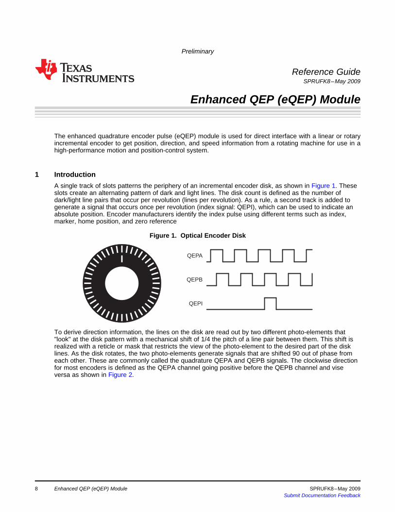
A single track of slots patterns the periphery of an incremental encoder disk, as shown in Figure 1. Theseslots create an alternating pattern of dark and light lines. The disk count is defined as the number ofdark/light line pairs that occur per revolution (lines per revolution). As a rule, a second track is added togenerate a signal that occurs once per revolution (index signal: QEPI), which can be used to indicate anabsolute position. Encoder manufacturers identify the index pulse using different terms such as index,marker, home position, and zero reference
Figure 1. Optical Encoder Disk
To derive direction information, the lines on the disk are read out by two different photo-elements that"look" at the disk pattern with a mechanical shift of 1/4 the pitch of a line pair between them. This shift isrealized with a reticle or mask that restricts the view of the photo-element to the desired part of the disklines. As the disk rotates, the two photo-elements generate signals that are shifted 90 out of phase fromeach other. These are commonly called the quadrature QEPA and QEPB signals. The clockwise directionfor most encoders is defined as the QEPA channel going positive before the QEPB channel and viseversa as shown in Figure 2.
Enhanced QEP (eQEP) Module8 SPRUFK8–May 2009Submit Documentation Feedback
T0
0 1 2 3 4 5 6 7 N−6 N−5 N−4 N−3 N−2 N−1 0
QEPA
QEPB
QEPI
Clockwise shaft rotation/forward movement
Anti-clockwise shaft rotation/reverse movement
0 N−1 N−2 N−3 N−4 N−5 N−6 N−7 6 5 4 3 2 1 0 N−1 N−2
QEPA
QEPB
QEPI
T0
Legend: N = lines per revolution
T0
0.25T0 ±0.1T0
0.5T0 ±0.1T0
T0 ±0.5T0
QEPA
QEPB
QEPI(gated toA and B)
QEPI(gated to A)
QEPI(ungated)
Preliminary
www.ti.com Introduction
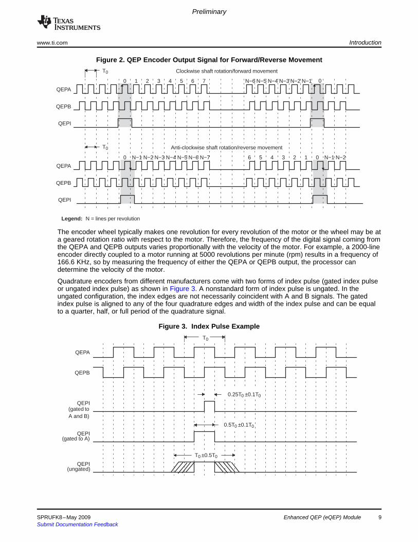
Figure 2. QEP Encoder Output Signal for Forward/Reverse Movement
The encoder wheel typically makes one revolution for every revolution of the motor or the wheel may be ata geared rotation ratio with respect to the motor. Therefore, the frequency of the digital signal coming fromthe QEPA and QEPB outputs varies proportionally with the velocity of the motor. For example, a 2000-lineencoder directly coupled to a motor running at 5000 revolutions per minute (rpm) results in a frequency of166.6 KHz, so by measuring the frequency of either the QEPA or QEPB output, the processor candetermine the velocity of the motor.
Quadrature encoders from different manufacturers come with two forms of index pulse (gated index pulseor ungated index pulse) as shown in Figure 3. A nonstandard form of index pulse is ungated. In theungated configuration, the index edges are not necessarily coincident with A and B signals. The gatedindex pulse is aligned to any of the four quadrature edges and width of the index pulse and can be equalto a quarter, half, or full period of the quadrature signal.
Figure 3. Index Pulse Example
SPRUFK8–May 2009 Enhanced QEP (eQEP) Module 9Submit Documentation Feedback

v(k) �x(k)� x(k� 1)
T�
�XT (1)
v(k) � Xt(k)� t(k� 1)
�X�T (2)
2 Description
Preliminary
Description www.ti.com
Some typical applications of shaft encoders include robotics and even computer input in the form of amouse. Inside your mouse you can see where the mouse ball spins a pair of axles (a left/right, and anup/down axle). These axles are connected to optical shaft encoders that effectively tell the computer howfast and in what direction the mouse is moving.
General Issues: Estimating velocity from a digital position sensor is a cost-effective strategy in motorcontrol. Two different first order approximations for velocity may be written as:
where
v(k): Velocity at time instant k
x(k): Position at time instant k
x(k-1): Position at time instant k-1
T: Fixed unit time or inverse of velocity calculation rate
∆X: Incremental position movement in unit time
t(k): Time instant "k"
t(k-1): Time instant "k-1"
X: Fixed unit position
∆T: Incremental time elapsed for unit position movement.
Equation 1 is the conventional approach to velocity estimation and it requires a time base to provide unittime event for velocity calculation. Unit time is basically the inverse of the velocity calculation rate.
The encoder count (position) is read once during each unit time event. The quantity [x(k) - x(k-1)] isformed by subtracting the previous reading from the current reading. Then the velocity estimate iscomputed by multiplying by the known constant 1/T (where T is the constant time between unit timeevents and is known in advance).
Estimation based on Equation 1 has an inherent accuracy limit directly related to the resolution of theposition sensor and the unit time period T. For example, consider a 500-line per revolution quadratureencoder with a velocity calculation rate of 400 Hz. When used for position the quadrature encoder gives afour-fold increase in resolution, in this case, 2000 counts per revolution. The minimum rotation that can bedetected is therefore 0.0005 revolutions, which gives a velocity resolution of 12 rpm when sampled at 400Hz. While this resolution may be satisfactory at moderate or high speeds, e.g. 1% error at 1200 rpm, itwould clearly prove inadequate at low speeds. In fact, at speeds below 12 rpm, the speed estimate woulderroneously be zero much of the time.
At low speed, Equation 2 provides a more accurate approach. It requires a position sensor that outputs afixed interval pulse train, such as the aforementioned quadrature encoder. The width of each pulse isdefined by motor speed for a given sensor resolution. Equation 2 can be used to calculate motor speed bymeasuring the elapsed time between successive quadrature pulse edges. However, this method suffersfrom the opposite limitation, as does Equation 1. A combination of relatively large motor speeds and highsensor resolution makes the time interval ∆T small, and thus more greatly influenced by the timerresolution. This can introduce considerable error into high-speed estimates.
For systems with a large speed range (that is, speed estimation is needed at both low and high speeds),one approach is to use Equation 2 at low speed and have the DSP software switch over to Equation 1when the motor speed rises above some specified threshold.
This section provides the eQEP inputs, memory map, and functional description.
10 Enhanced QEP (eQEP) Module SPRUFK8–May 2009Submit Documentation Feedback
2.1 EQEP Inputs
2.2 Functional Description
Preliminary
www.ti.com Description
The eQEP inputs include two pins for quadrature-clock mode or direction-count mode, an index (or 0marker), and a strobe input.• QEPA/XCLK and QEPB/XDIR
These two pins can be used in quadrature-clock mode or direction-count mode.– Quadrature-clock Mode
The eQEP encoders provide two square wave signals (A and B) 90 electrical degrees out of phasewhose phase relationship is used to determine the direction of rotation of the input shaft andnumber of eQEP pulses from the index position to derive the relative position information. Forforward or clockwise rotation, QEPA signal leads QEPB signal and vice versa. The quadraturedecoder uses these two inputs to generate quadrature-clock and direction signals.
– Direction-count ModeIn direction-count mode, direction and clock signals are provided directly from the external source.Some position encoders have this type of output instead of quadrature output. The QEPA pinprovides the clock input and the QEPB pin provides the direction input.
• eQEPI: Index or Zero MarkerThe eQEP encoder uses an index signal to assign an absolute start position from which positioninformation is incrementally encoded using quadrature pulses. This pin is connected to the indexoutput of the eQEP encoder to optionally reset the position counter for each revolution. This signal canbe used to initialize or latch the position counter on the occurrence of a desired event on the index pin.
• QEPS: Strobe InputThis general-purpose strobe signal can initialize or latch the position counter on the occurrence of adesired event on the strobe pin. This signal is typically connected to a sensor or limit switch to notifythat the motor has reached a defined position.
The eQEP peripheral contains the following major functional units (as shown in Figure 4):• Programmable input qualification for each pin (part of the GPIO MUX)• Quadrature decoder unit (QDU)• Position counter and control unit for position measurement (PCCU)• Quadrature edge-capture unit for low-speed measurement (QCAP)• Unit time base for speed/frequency measurement (UTIME)• Watchdog timer for detecting stalls (QWDOG)
SPRUFK8–May 2009 Enhanced QEP (eQEP) Module 11Submit Documentation Feedback

QWDTMR
QWDPRD
16
QWDOGUTIME
QUPRD
QUTMR
32
UTOUT
WDTOUT
Quadraturecapture unit
(QCAP)QCPRDLAT
QCTMRLAT
16
QFLG
QEPSTS
QEPCTL
Registersused by
multiple units
QCLK
QDIR
QI
QS
PHE
PCSOUT
Quadraturedecoder(QDU)
QDECCTL
16
Position counter/control unit
(PCCU)QPOSLAT
QPOSSLAT
32
QPOSILAT
EQEPxAIN
EQEPxBIN
EQEPxIINEQEPxIOUT
EQEPxIOE
EQEPxSIN
EQEPxSOUT
EQEPxSOE
GPIOMUX
EQEPxA/XCLK
EQEPxB/XDIR
EQEPxS
EQEPxI
QPOSCMP QEINT
QFRC
32
QCLR
QPOSCTL
1632
QPOSCNT
QPOSMAXQPOSINIT
PIEEQEPxINT
Enhanced QEP (eQEP) peripheral
Systemcontrol registers
QCTMRQCPRD
1616
QCAPCTL
EQEPxENCLKSYSCLKOUT
Dat
a bu
s
To CPU
2.3 eQEP Memory Map
Preliminary
Description www.ti.com
Figure 4. Functional Block Diagram of the eQEP Peripheral
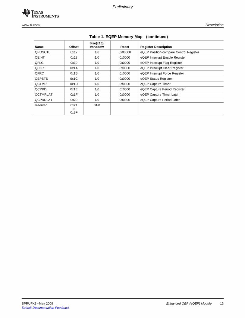
Table 1 lists the registers with their memory locations, sizes, and reset values.
Table 1. EQEP Memory MapSize(x16)/
Name Offset #shadow Reset Register DescriptionQPOSCNT 0x00 2/0 0x00000000 eQEP Position CounterQPOSINIT 0x02 2/0 0x00000000 eQEP Initialization Position CountQPOSMAX 0x04 2/0 0x00000000 eQEP Maximum Position CountQPOSCMP 0x06 2/1 0x00000000 eQEP Position-compareQPOSILAT 0x08 2/0 0x00000000 eQEP Index Position LatchQPOSSLAT 0x0A 2/0 0x00000000 eQEP Strobe Position LatchQPOSLAT 0x0C 2/0 0x00000000 eQEP Position LatchQUTMR 0x0E 2/0 0x00000000 QEP Unit TimerQUPRD 0x10 2/0 0x00000000 eQEP Unit Period RegisterQWDTMR 0x12 1/0 0x0000 eQEP Watchdog TimerQWDPRD 0x13 1/0 0x0000 eQEP Watchdog Period RegisterQDECCTL 0x14 1/0 0x0000 eQEP Decoder Control RegisterQEPCTL 0x15 1/0 0x0000 eQEP Control RegisterQCAPCTL 0x16 1/0 0x0000 eQEP Capture Control Register
12 Enhanced QEP (eQEP) Module SPRUFK8–May 2009Submit Documentation Feedback
Preliminary
www.ti.com Description
Table 1. EQEP Memory Map (continued)Size(x16)/
Name Offset #shadow Reset Register DescriptionQPOSCTL 0x17 1/0 0x00000 eQEP Position-compare Control RegisterQEINT 0x18 1/0 0x0000 eQEP Interrupt Enable RegisterQFLG 0x19 1/0 0x0000 eQEP Interrupt Flag RegisterQCLR 0x1A 1/0 0x0000 eQEP Interrupt Clear RegisterQFRC 0x1B 1/0 0x0000 eQEP Interrupt Force RegisterQEPSTS 0x1C 1/0 0x0000 eQEP Status RegisterQCTMR 0x1D 1/0 0x0000 eQEP Capture TimerQCPRD 0x1E 1/0 0x0000 eQEP Capture Period RegisterQCTMRLAT 0x1F 1/0 0x0000 eQEP Capture Timer LatchQCPRDLAT 0x20 1/0 0x0000 eQEP Capture Period Latchreserved 0x21 31/0
to0x3F
SPRUFK8–May 2009 Enhanced QEP (eQEP) Module 13Submit Documentation Feedback
3 Quadrature Decoder Unit (QDU)
0
1
1
0
QA
QB
1
1
0
0
����������
Quadraturedecoder
0001
1011
iCLK
xCLKxCLKxCLK
01
1110
00iDIRxDIR
1
0
������������
2
����� �
PHE
����������
x1x2
x1, x2
�����������
0
11
0
���������
QDECCTL:IGATE
QCLK
QDIR
QI
1
0
����������
0
1
QDECCTL:SPSEL
QDECCTL:SPSEL
1
0QDECCTL:SOEN
QS
�����
EQEPxIOE
EQEPxSOE
��� ����
��� �����
EQEPxSIN
EQEPxIIN
EQEPxBIN
EQEPxAIN
����������� �� �������
EQEPA
EQEPB
3.1 Position Counter Input Modes
Preliminary
Quadrature Decoder Unit (QDU) www.ti.com
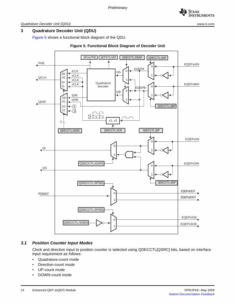
Figure 5 shows a functional block diagram of the QDU.
Figure 5. Functional Block Diagram of Decoder Unit
Clock and direction input to position counter is selected using QDECCTL[QSRC] bits, based on interfaceinput requirement as follows:• Quadrature-count mode• Direction-count mode• UP-count mode• DOWN-count mode
14 Enhanced QEP (eQEP) Module SPRUFK8–May 2009Submit Documentation Feedback
3.1.1 Quadrature Count Mode
(00)
(10)
(11)
(01)(A,B)=
QEPA
QEPB
eQEP signals
10
01
00 11
Incrementcounter
Decrementcounter
Decrementcounter
Incrementcounter
Decrementcounter
Decrementcounter
Incrementcounter
Incrementcounter
Preliminary
www.ti.com Quadrature Decoder Unit (QDU)
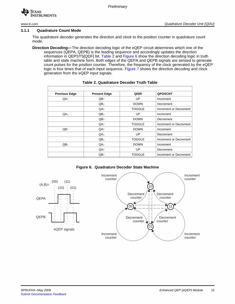
The quadrature decoder generates the direction and clock to the position counter in quadrature countmode.
Direction Decoding—The direction decoding logic of the eQEP circuit determines which one of thesequences (QEPA, QEPB) is the leading sequence and accordingly updates the directioninformation in QEPSTS[QDF] bit. Table 2 and Figure 6 show the direction decoding logic in truthtable and state machine form. Both edges of the QEPA and QEPB signals are sensed to generatecount pulses for the position counter. Therefore, the frequency of the clock generated by the eQEPlogic is four times that of each input sequence. Figure 7 shows the direction decoding and clockgeneration from the eQEP input signals.
Table 2. Quadrature Decoder Truth Table.
Previous Edge Present Edge QDIR QPOSCNTQA↑ QB↑ UP Increment
QB↓ DOWN DecrementQA↓ TOGGLE Increment or Decrement
QA↓ QB↓ UP IncrementQB↑ DOWN DecrementQA↑ TOGGLE Increment or Decrement
QB↑ QA↑ DOWN IncrementQA↓ UP DecrementQB↓ TOGGLE Increment or Decrement
QB↓ QA↓ DOWN IncrementQA↑ UP DecrementQB↑ TOGGLE Increment or Decrement
Figure 6. Quadrature Decoder State Machine
SPRUFK8–May 2009 Enhanced QEP (eQEP) Module 15Submit Documentation Feedback
+1 +1 +1+1 +1+1+1 −1 −1 −1−1 −1−1−1−1 −1−1 −1 +1+1+1
−1 −1 −1 −1 −1 −1 −1 +1 +1 +1 +1 +1 +1 +1+1+1+1 +1 −1−1−1
QA
QB
QCLK
QDIR
QPOSCNT
QA
QB
QCLK
QDIR
QPOSCNT
3.1.2 Direction-count Mode
3.1.3 Up-Count Mode
Preliminary
Quadrature Decoder Unit (QDU) www.ti.com
Figure 7. Quadrature-clock and Direction Decoding
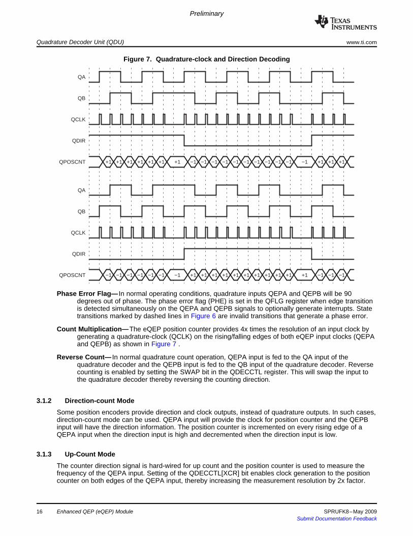
Phase Error Flag— In normal operating conditions, quadrature inputs QEPA and QEPB will be 90degrees out of phase. The phase error flag (PHE) is set in the QFLG register when edge transitionis detected simultaneously on the QEPA and QEPB signals to optionally generate interrupts. Statetransitions marked by dashed lines in Figure 6 are invalid transitions that generate a phase error.
Count Multiplication—The eQEP position counter provides 4x times the resolution of an input clock bygenerating a quadrature-clock (QCLK) on the rising/falling edges of both eQEP input clocks (QEPAand QEPB) as shown in Figure 7 .
Reverse Count— In normal quadrature count operation, QEPA input is fed to the QA input of thequadrature decoder and the QEPB input is fed to the QB input of the quadrature decoder. Reversecounting is enabled by setting the SWAP bit in the QDECCTL register. This will swap the input tothe quadrature decoder thereby reversing the counting direction.
Some position encoders provide direction and clock outputs, instead of quadrature outputs. In such cases,direction-count mode can be used. QEPA input will provide the clock for position counter and the QEPBinput will have the direction information. The position counter is incremented on every rising edge of aQEPA input when the direction input is high and decremented when the direction input is low.
The counter direction signal is hard-wired for up count and the position counter is used to measure thefrequency of the QEPA input. Setting of the QDECCTL[XCR] bit enables clock generation to the positioncounter on both edges of the QEPA input, thereby increasing the measurement resolution by 2x factor.
Enhanced QEP (eQEP) Module16 SPRUFK8–May 2009Submit Documentation Feedback
3.1.4 Down-Count Mode
3.2 eQEP Input Polarity Selection
3.3 Position-Compare Sync Output
4 Position Counter and Control Unit (PCCU)
4.1 Position Counter Operating Modes
4.1.1 Position Counter Reset on Index Event (QEPCTL[PCRM]=00)
Preliminary
www.ti.com Position Counter and Control Unit (PCCU)
The counter direction signal is hardwired for a down count and the position counter is used to measure thefrequency of the QEPA input. Setting of the QDECCTL[XCR] bit enables clock generation to the positioncounter on both edges of a QEPA input, thereby increasing the measurement resolution by 2x factor.
Each eQEP input can be inverted using QDECCTL[8:5] control bits. As an example, setting ofQDECCTL[QIP] bit will invert the index input.
The enhanced eQEP peripheral includes a position-compare unit that is used to generate theposition-compare sync signal on compare match between the position counter register (QPOSCNT) andthe position-compare register (QPOSCMP). This sync signal can be output using an index pin or strobepin of the EQEP peripheral.
Setting the QDECCTL[SOEN] bit enables the position-compare sync output and the QDECCTL[SPSEL] bitselects either an eQEP index pin or an eQEP strobe pin.
The position counter and control unit provides two configuration registers (QEPCTL and QPOSCTL) forsetting up position counter operational modes, position counter initialization/latch modes andposition-compare logic for sync signal generation.
Position counter data may be captured in different manners. In some systems, the position counter isaccumulated continuously for multiple revolutions and the position counter value provides the positioninformation with respect to the known reference. An example of this is the quadrature encoder mounted onthe motor controlling the print head in the printer. Here the position counter is reset by moving the printhead to the home position and then position counter provides absolute position information with respect tohome position.
In other systems, the position counter is reset on every revolution using index pulse and position counterprovides rotor angle with respect to index pulse position.
Position counter can be configured to operate in following four modes• Position Counter Reset on Index Event• Position Counter Reset on Maximum Position• Position Counter Reset on the first Index Event• Position Counter Reset on Unit Time Out Event (Frequency Measurement)
In all the above operating modes, position counter is reset to 0 on overflow and to QPOSMAX registervalue on underflow. Overflow occurs when the position counter counts up after QPOSMAX value.Underflow occurs when position counter counts down after "0". Interrupt flag is set to indicateoverflow/underflow in QFLG register.
If the index event occurs during the forward movement, then position counter is reset to 0 on the nexteQEP clock. If the index event occurs during the reverse movement, then the position counter is reset tothe value in the QPOSMAX register on the next eQEP clock.
First index marker is defined as the quadrature edge following the first index edge. The eQEP peripheralrecords the occurrence of the first index marker (QEPSTS[FIMF]) and direction on the first index eventmarker (QEPSTS[FIDF]) in QEPSTS registers, it also remembers the quadrature edge on the first indexmarker so that same relative quadrature transition is used for index event reset operation.
SPRUFK8–May 2009 Enhanced QEP (eQEP) Module 17Submit Documentation Feedback
F9D
F9E
0
F9F
321 4 3 12
F9D
F9E
F9F
0
F9B
F9C F9A
F97
F98
F99
QA
QB
QCLK
QEPSTS:QDF
QPOSCNT F9C 4 5
F9F 0
QI
Index interrupt/ index event
marker
QPOSILAT
QEPSTS:QDLF
4.1.2 Position Counter Reset on Maximum Position (QEPCTL[PCRM]=01)
Preliminary
Position Counter and Control Unit (PCCU) www.ti.com
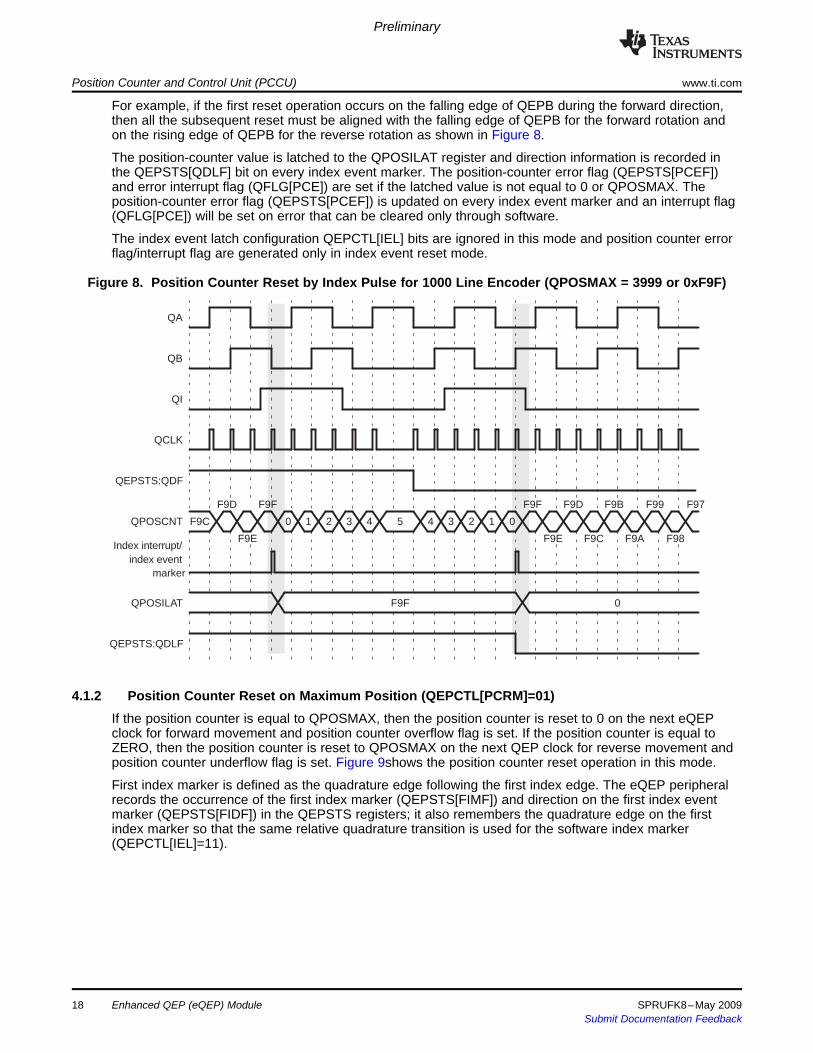
For example, if the first reset operation occurs on the falling edge of QEPB during the forward direction,then all the subsequent reset must be aligned with the falling edge of QEPB for the forward rotation andon the rising edge of QEPB for the reverse rotation as shown in Figure 8.
The position-counter value is latched to the QPOSILAT register and direction information is recorded inthe QEPSTS[QDLF] bit on every index event marker. The position-counter error flag (QEPSTS[PCEF])and error interrupt flag (QFLG[PCE]) are set if the latched value is not equal to 0 or QPOSMAX. Theposition-counter error flag (QEPSTS[PCEF]) is updated on every index event marker and an interrupt flag(QFLG[PCE]) will be set on error that can be cleared only through software.
The index event latch configuration QEPCTL[IEL] bits are ignored in this mode and position counter errorflag/interrupt flag are generated only in index event reset mode.
Figure 8. Position Counter Reset by Index Pulse for 1000 Line Encoder (QPOSMAX = 3999 or 0xF9F)
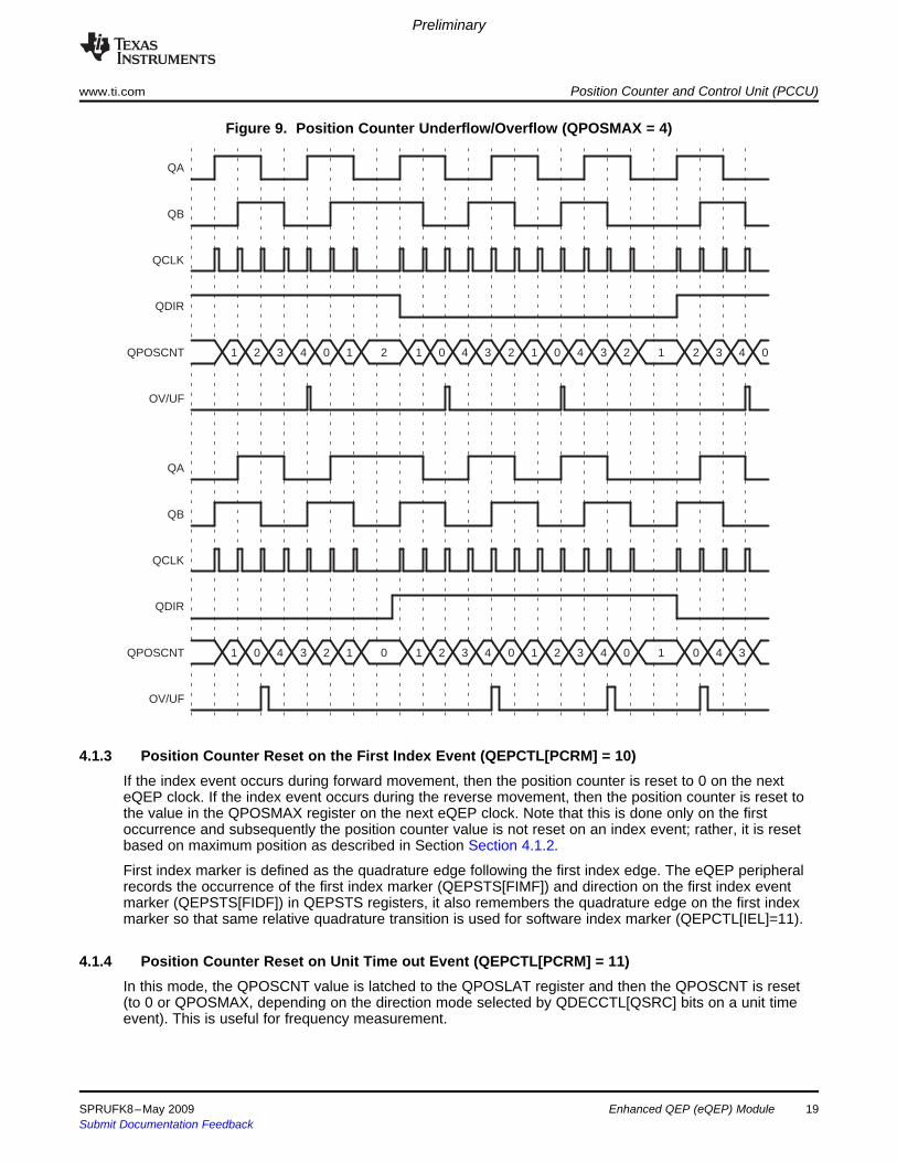
If the position counter is equal to QPOSMAX, then the position counter is reset to 0 on the next eQEPclock for forward movement and position counter overflow flag is set. If the position counter is equal toZERO, then the position counter is reset to QPOSMAX on the next QEP clock for reverse movement andposition counter underflow flag is set. Figure 9shows the position counter reset operation in this mode.
First index marker is defined as the quadrature edge following the first index edge. The eQEP peripheralrecords the occurrence of the first index marker (QEPSTS[FIMF]) and direction on the first index eventmarker (QEPSTS[FIDF]) in the QEPSTS registers; it also remembers the quadrature edge on the firstindex marker so that the same relative quadrature transition is used for the software index marker(QEPCTL[IEL]=11).
Enhanced QEP (eQEP) Module18 SPRUFK8–May 2009Submit Documentation Feedback
QA
QB
QCLK
QDIR
QPOSCNT
OV/UF
QA
QB
QCLK
QDIR
QPOSCNT
OV/UF
1 2 3 4 0 1 2 1 0 4 3 2 1 0 4 3 2 1 2 3 4 0
1 0 4 3 2 1 0 1 2 3 4 0 1 2 3 4 0 1 0 4 3
4.1.3 Position Counter Reset on the First Index Event (QEPCTL[PCRM] = 10)
4.1.4 Position Counter Reset on Unit Time out Event (QEPCTL[PCRM] = 11)
Preliminary
www.ti.com Position Counter and Control Unit (PCCU)
Figure 9. Position Counter Underflow/Overflow (QPOSMAX = 4)
If the index event occurs during forward movement, then the position counter is reset to 0 on the nexteQEP clock. If the index event occurs during the reverse movement, then the position counter is reset tothe value in the QPOSMAX register on the next eQEP clock. Note that this is done only on the firstoccurrence and subsequently the position counter value is not reset on an index event; rather, it is resetbased on maximum position as described in Section Section 4.1.2.
First index marker is defined as the quadrature edge following the first index edge. The eQEP peripheralrecords the occurrence of the first index marker (QEPSTS[FIMF]) and direction on the first index eventmarker (QEPSTS[FIDF]) in QEPSTS registers, it also remembers the quadrature edge on the first indexmarker so that same relative quadrature transition is used for software index marker (QEPCTL[IEL]=11).
In this mode, the QPOSCNT value is latched to the QPOSLAT register and then the QPOSCNT is reset(to 0 or QPOSMAX, depending on the direction mode selected by QDECCTL[QSRC] bits on a unit timeevent). This is useful for frequency measurement.
SPRUFK8–May 2009 Enhanced QEP (eQEP) Module 19Submit Documentation Feedback
4.2 Position Counter Latch
4.2.1 Index Event Latch
Preliminary
Position Counter and Control Unit (PCCU) www.ti.com
The eQEP index and strobe input can be configured to latch the position counter (QPOSCNT) intoQPOSILAT and QPOSSLAT, respectively, on occurrence of a definite event on these pins.
In some applications, it may not be desirable to reset the position counter on every index event andinstead it may be required to operate the position counter in full 32-bit mode (QEPCTL[PCRM] = 01 andQEPCTL[PCRM] = 10 modes).
In such cases, the eQEP position counter can be configured to latch on the following events and directioninformation is recorded in the QEPSTS[QDLF] bit on every index event marker.• Latch on Rising edge (QEPCTL[IEL]=01)• Latch on Falling edge (QEPCTL[IEL]=10)• Latch on Index Event Marker (QEPCTL[IEL]=11)
This is particularly useful as an error checking mechanism to check if the position counter accumulatedthe correct number of counts between index events. As an example, the 1000-line encoder must count4000 times when moving in the same direction between the index events.
The index event latch interrupt flag (QFLG[IEL]) is set when the position counter is latched to theQPOSILAT register. The index event latch configuration bits (QEPCTZ[IEL]) are ignored whenQEPCTL[PCRM] = 00.
Latch on Rising Edge (QEPCTL[IEL]=01)—The position counter value (QPOSCNT) is latched to theQPOSILAT register on every rising edge of an index input.
Latch on Falling Edge (QEPCTL[IEL] = 10)—The position counter value (QPOSCNT) is latched to theQPOSILAT register on every falling edge of index input.
Latch on Index Event Marker/Software Index Marker (QEPCTL[IEL] = 11—The first index marker isdefined as the quadrature edge following the first index edge. The eQEP peripheral records theoccurrence of the first index marker (QEPSTS[FIMF]) and direction on the first index event marker(QEPSTS[FIDF]) in the QEPSTS registers. It also remembers the quadrature edge on the firstindex marker so that same relative quadrature transition is used for latching the position counter(QEPCTL[IEL]=11).
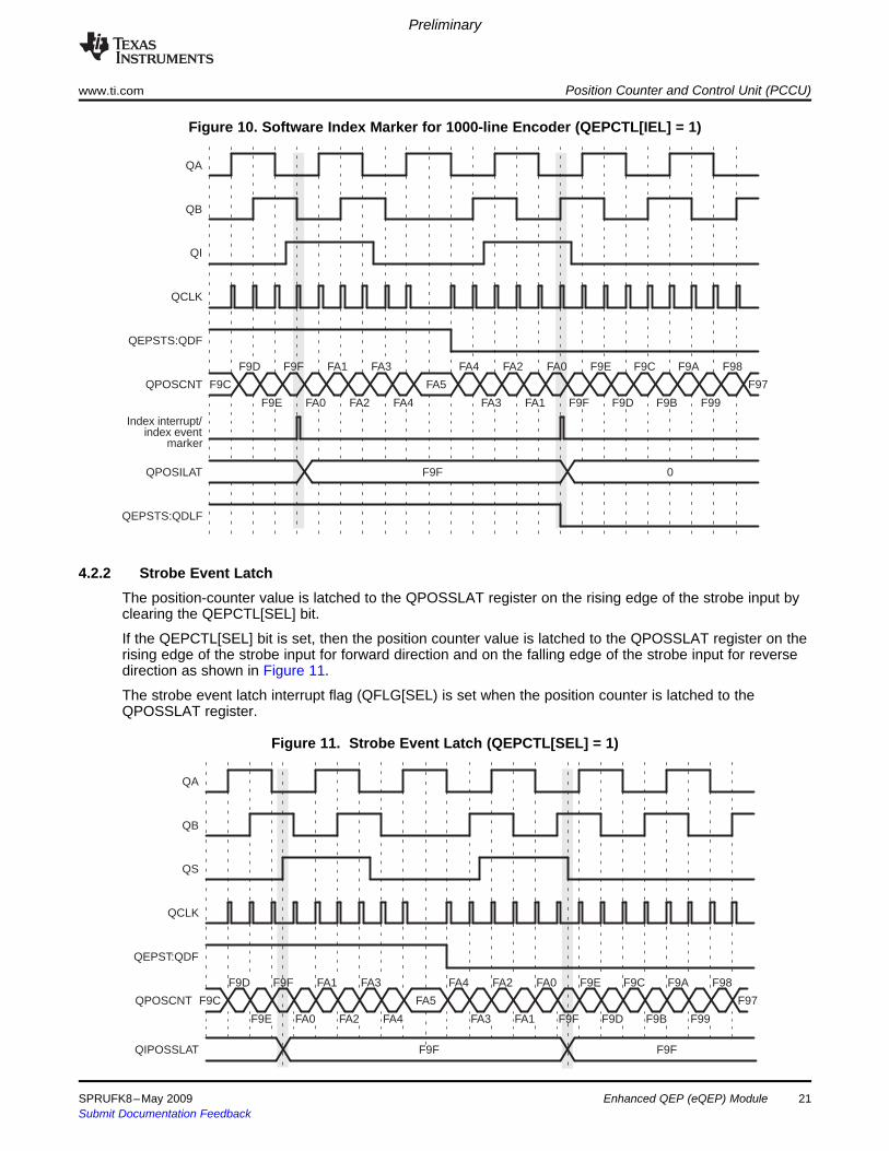
Figure 10 shows the position counter latch using an index event marker.
Enhanced QEP (eQEP) Module20 SPRUFK8–May 2009Submit Documentation Feedback
F9C
F9D
F9E
F9F
FA0
FA1
FA2
FA3
FA4
FA5
FA4
FA3
FA2
FA1
FA0
F9F
F9E
F9D
F9C
F9B
F9A
F99
F98
F97
F9F 0
QA
QB
QI
QCLK
QEPSTS:QDF
QPOSCNT
Index interrupt/index event
marker
QPOSILAT
QEPSTS:QDLF
4.2.2 Strobe Event Latch
F9C
F9D
F9E
F9F
FA0
FA1
FA2
FA3
FA4
FA5
FA4
FA3
FA2
FA1
FA0
F9F
F9E
F9D
F9C
F9B
F9A
F99
F98
F97
F9F F9F
QA
QB
QS
QCLK
QEPST:QDF
QPOSCNT
QIPOSSLAT
Preliminary
www.ti.com Position Counter and Control Unit (PCCU)
Figure 10. Software Index Marker for 1000-line Encoder (QEPCTL[IEL] = 1)
The position-counter value is latched to the QPOSSLAT register on the rising edge of the strobe input byclearing the QEPCTL[SEL] bit.
If the QEPCTL[SEL] bit is set, then the position counter value is latched to the QPOSSLAT register on therising edge of the strobe input for forward direction and on the falling edge of the strobe input for reversedirection as shown in Figure 11.
The strobe event latch interrupt flag (QFLG[SEL) is set when the position counter is latched to theQPOSSLAT register.
Figure 11. Strobe Event Latch (QEPCTL[SEL] = 1)
SPRUFK8–May 2009 Enhanced QEP (eQEP) Module 21Submit Documentation Feedback
4.3 Position Counter Initialization
4.4 eQEP Position-compare Unit
QPOSCTL:PCSPW
8
Pulsestretcher
QFLG:PCM
QPOSCNT
32
QPOSCMP QFLG:PCR
32
QPOSCTL:PCSHDW
QPOSCTL:PCLOAD
0
1
QPOSCTL:PCPOL
PCSOUT
PCEVENT
Preliminary
Position Counter and Control Unit (PCCU) www.ti.com
The position counter can be initialized using following events:• Index event• Strobe event• Software initialization
Index Event Initialization (IEI)—The QEPI index input can be used to trigger the initialization of theposition counter at the rising or falling edge of the index input. If the QEPCTL[IEI] bits are 10, thenthe position counter (QPOSCNT) is initialized with a value in the QPOSINIT register on the risingedge of index input. Conversely, if the QEPCTL[IEI] bits are 11, initialization will be on the fallingedge of the index input.
Strobe Event Initialization (SEI)— If the QEPCTL[SEI] bits are 10, then the position counter is initializedwith a value in the QPOSINIT register on the rising edge of strobe input.If QEPCTL[SEL] bits are 11, then the position counter is initialized with a value in the QPOSINITregister on the rising edge of strobe input for forward direction and on the falling edge of strobeinput for reverse direction.
Software Initialization (SWI)—The position counter can be initialized in software by writing a 1 to theQEPCTL[SWI] bit. This bit is not automatically cleared. While the bit is still set, if a 1 is written to itagain, the position counter will be re-initialized.
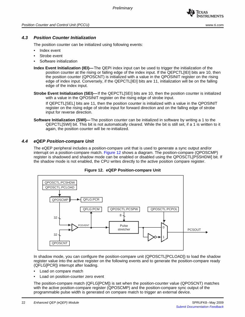
The eQEP peripheral includes a position-compare unit that is used to generate a sync output and/orinterrupt on a position-compare match. Figure 12 shows a diagram. The position-compare (QPOSCMP)register is shadowed and shadow mode can be enabled or disabled using the QPOSCTL[PSSHDW] bit. Ifthe shadow mode is not enabled, the CPU writes directly to the active position compare register.
Figure 12. eQEP Position-compare Unit
In shadow mode, you can configure the position-compare unit (QPOSCTL[PCLOAD]) to load the shadowregister value into the active register on the following events and to generate the position-compare ready(QFLG[PCR]) interrupt after loading.• Load on compare match• Load on position-counter zero event
The position-compare match (QFLG[PCM]) is set when the position-counter value (QPOSCNT) matcheswith the active position-compare register (QPOSCMP) and the position-compare sync output of theprogrammable pulse width is generated on compare match to trigger an external device.
22 Enhanced QEP (eQEP) Module SPRUFK8–May 2009Submit Documentation Feedback

POSCMP=2
0
1
2
3
4
3
2
1
0
1
2
3
4
3
2
1
0
eQEP counter
PCEVNT
PCSOUT (active HIGH)
PCSOUT (active LOW)
PCSPW
DIR
QPOSCMP
QPOSCNT
PCSOUT (active HIGH)
PCSPW PCSPWPCSPW
PCEVNT
Preliminary
www.ti.com Position Counter and Control Unit (PCCU)
For example, if QPOSCMP = 2, the position-compare unit generates a position-compare event on 1 to 2transitions of the eQEP position counter for forward counting direction and on 3 to 2 transitions of theeQEP position counter for reverse counting direction (see Figure 13).
Figure 23 shows the layout of the eQEP Position-Compare Control Register (QPOSCTL) and Table 5describes the QPOSCTL bit fields.
Figure 13. eQEP Position-compare Event Generation Points
The pulse stretcher logic in the position-compare unit generates a programmable position-compare syncpulse output on the position-compare match. In the event of a new position-compare match while aprevious position-compare pulse is still active, then the pulse stretcher generates a pulse of specifiedduration from the new position-compare event as shown in Figure 14.
Figure 14. eQEP Position-compare Sync Output Pulse Stretcher
SPRUFK8–May 2009 Enhanced QEP (eQEP) Module 23Submit Documentation Feedback

5 eQEP Edge Capture Unit
v(k) � Xt(k)� t(k� 1)
�X�T (3)
Preliminary
eQEP Edge Capture Unit www.ti.com
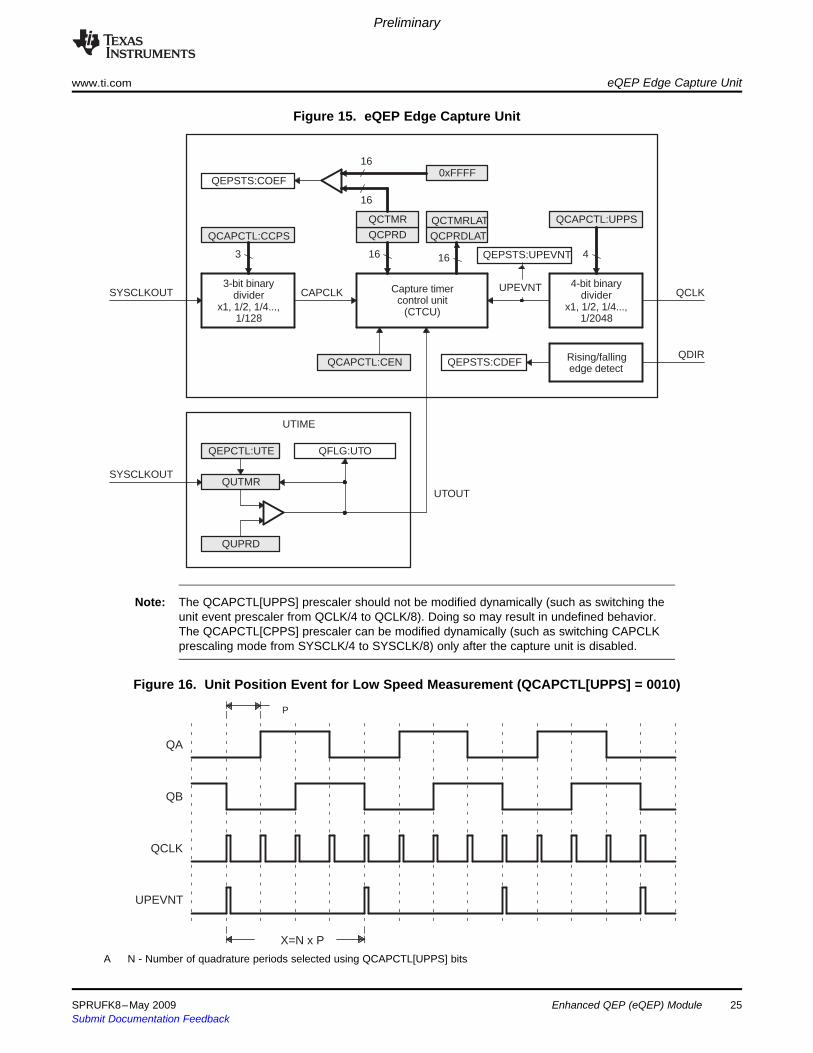
The eQEP peripheral includes an integrated edge capture unit to measure the elapsed time between theunit position events as shown in Figure 15. This feature is typically used for low speed measurement usingthe following equation:
where,• X - Unit position is defined by integer multiple of quadrature edges (see Figure 16)• ∆T - Elapsed time between unit position events• v(k) - Velocity at time instant "k"
The eQEP capture timer (QCTMR) runs from prescaled SYSCLKOUT and the prescaler is programmedby the QCAPCTL[CCPS] bits. The capture timer (QCTMR) value is latched into the capture period register(QCPRD) on every unit position event and then the capture timer is reset, a flag is set inQEPSTS:UPEVNT to indicate that new value is latched into the QCPRD register. Software can check thisstatus flag before reading the period register for low speed measurement and clear the flag by writing 1.
Time measurement (∆T) between unit position events will be correct if the following conditions are met:• No more than 65,535 counts have occurred between unit position events.• No direction change between unit position events.
The capture unit sets the eQEP overflow error flag (QEPSTS[COEF]) in the event of capture timeroverflow between unit position events. If a direction change occurs between the unit position events, thenan error flag is set in the status register (QEPSTS[CDEF]).
Capture Timer (QCTMR) and Capture period register (QCPRD) can be configured to latch on followingevents.• CPU read of QPOSCNT register• Unit time-out event
If the QEPCTL[QCLM] bit is cleared, then the capture timer and capture period values are latched into theQCTMRLAT and QCPRDLAT registers, respectively, when the CPU reads the position counter(QPOSCNT).
If the QEPCTL[QCLM] bit is set, then the position counter, capture timer, and capture period values arelatched into the QPOSLAT, QCTMRLAT and QCPRDLAT registers, respectively, on unit time out.
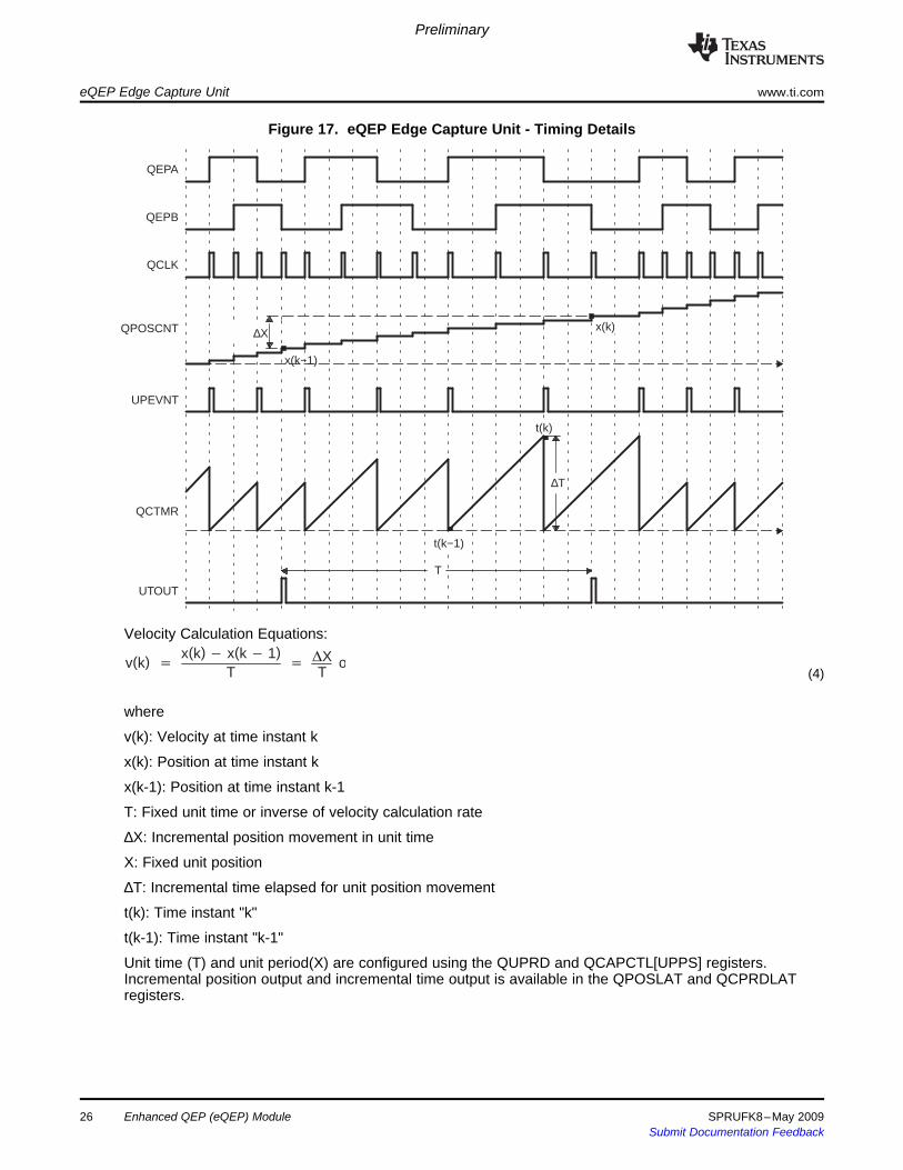
Figure 17 shows the capture unit operation along with the position counter.
Enhanced QEP (eQEP) Module24 SPRUFK8–May 2009Submit Documentation Feedback
QCAPCTL:CEN
Capture timercontrol unit
(CTCU)
QCPRD
QCTMR QCTMRLAT
QCPRDLAT
16 16
3-bit binarydivider
x1, 1/2, 1/4...,1/128
CAPCLK
QCAPCTL:CCPS
3
SYSCLKOUT
16
0xFFFF16
QEPSTS:COEF
x1, 1/2, 1/4...,1/2048
4-bit binarydivider QCLK
Rising/fallingedge detect
QDIRQEPSTS:CDEF
QEPCTL:UTE
QUTMR
QUPRD
SYSCLKOUT
QFLG:UTO
UTIME
4
QCAPCTL:UPPS
UTOUT
QEPSTS:UPEVNT
UPEVNT
X=N x P
P
QA
QB
QCLK
UPEVNT
Preliminary
www.ti.com eQEP Edge Capture Unit
Figure 15. eQEP Edge Capture Unit
Note: The QCAPCTL[UPPS] prescaler should not be modified dynamically (such as switching theunit event prescaler from QCLK/4 to QCLK/8). Doing so may result in undefined behavior.The QCAPCTL[CPPS] prescaler can be modified dynamically (such as switching CAPCLKprescaling mode from SYSCLK/4 to SYSCLK/8) only after the capture unit is disabled.
Figure 16. Unit Position Event for Low Speed Measurement (QCAPCTL[UPPS] = 0010)
A N - Number of quadrature periods selected using QCAPCTL[UPPS] bits
SPRUFK8–May 2009 Enhanced QEP (eQEP) Module 25Submit Documentation Feedback
∆X
x(k−1)
∆T
t(k)
t(k−1)
T
QEPA
QEPB
QCLK
QPOSCNT
UPEVNT
QCTMR
UTOUT
x(k)
v(k) �x(k)� x(k� 1)
T�
�XT
or(4)
Preliminary
eQEP Edge Capture Unit www.ti.com
Figure 17. eQEP Edge Capture Unit - Timing Details
Velocity Calculation Equations:
where
v(k): Velocity at time instant k
x(k): Position at time instant k
x(k-1): Position at time instant k-1
T: Fixed unit time or inverse of velocity calculation rate
∆X: Incremental position movement in unit time
X: Fixed unit position
∆T: Incremental time elapsed for unit position movement
t(k): Time instant "k"
t(k-1): Time instant "k-1"
Unit time (T) and unit period(X) are configured using the QUPRD and QCAPCTL[UPPS] registers.Incremental position output and incremental time output is available in the QPOSLAT and QCPRDLATregisters.
Enhanced QEP (eQEP) Module26 SPRUFK8–May 2009Submit Documentation Feedback
6 eQEP Watchdog
QFLG:WTOQWDPRD
16
QWDTMR
16
QEPCTL:WDEQWDOG
RESET
SYSCLKOUT/64
SYSCLKOUT
QCLK WDTOUT
7 Unit Timer Base
Preliminary
www.ti.com eQEP Watchdog
Parameter Relevant Register to Configure or Read the InformationT Unit Period Register (QUPRD)
∆X Incremental Position = QPOSLAT(k) - QPOSLAT(K-1)X Fixed unit position defined by sensor resolution and ZCAPCTL[UPPS] bits
∆T Capture Period Latch (QCPRDLAT)
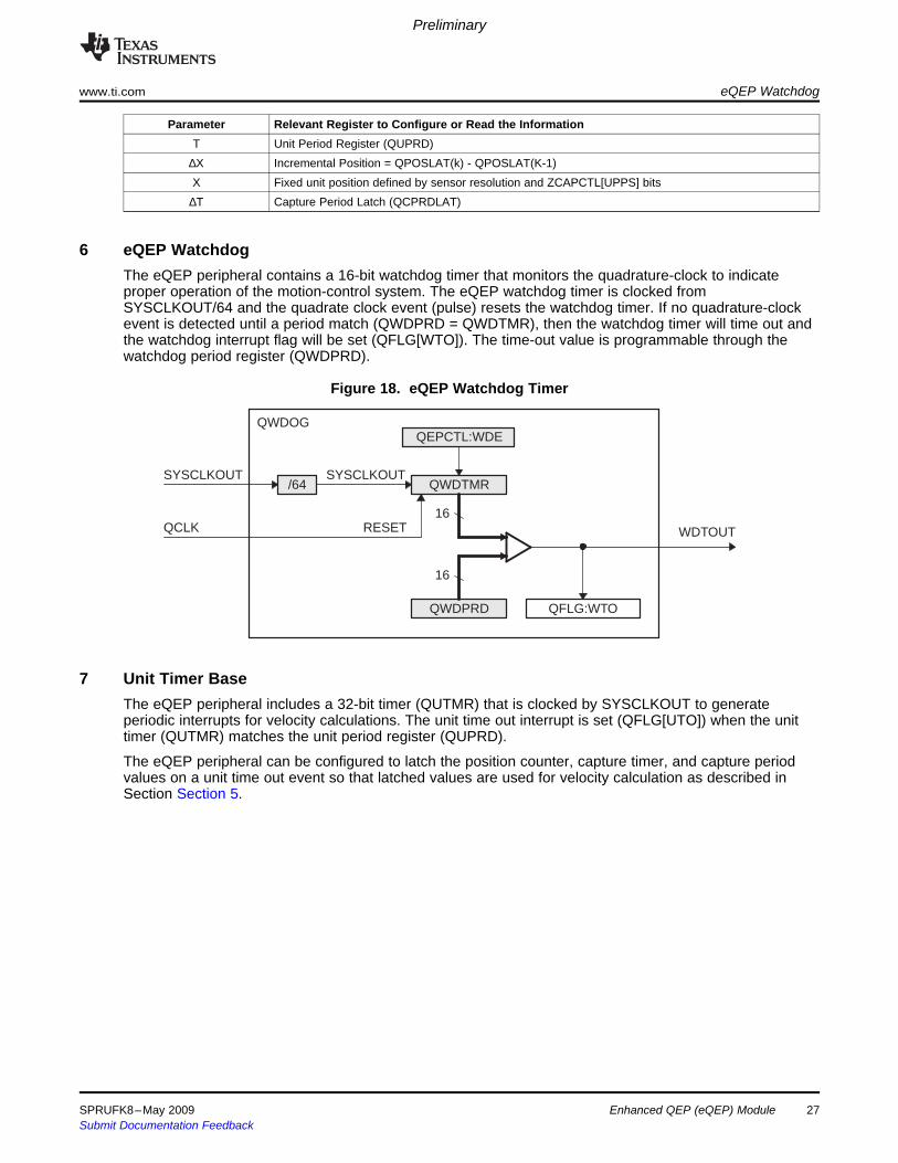
The eQEP peripheral contains a 16-bit watchdog timer that monitors the quadrature-clock to indicateproper operation of the motion-control system. The eQEP watchdog timer is clocked fromSYSCLKOUT/64 and the quadrate clock event (pulse) resets the watchdog timer. If no quadrature-clockevent is detected until a period match (QWDPRD = QWDTMR), then the watchdog timer will time out andthe watchdog interrupt flag will be set (QFLG[WTO]). The time-out value is programmable through thewatchdog period register (QWDPRD).
Figure 18. eQEP Watchdog Timer
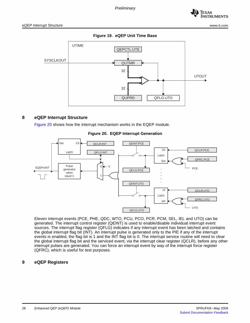
The eQEP peripheral includes a 32-bit timer (QUTMR) that is clocked by SYSCLKOUT to generateperiodic interrupts for velocity calculations. The unit time out interrupt is set (QFLG[UTO]) when the unittimer (QUTMR) matches the unit period register (QUPRD).
The eQEP peripheral can be configured to latch the position counter, capture timer, and capture periodvalues on a unit time out event so that latched values are used for velocity calculation as described inSection Section 5.
SPRUFK8–May 2009 Enhanced QEP (eQEP) Module 27Submit Documentation Feedback
QFLG:UTOQUPRD
32
QUTMR
32
QEPCTL:UTEUTIME
SYSCLKOUT
UTOUT
8 eQEP Interrupt Structure
Clr
Set
Latch
QFRC:PCE
PCE
QCLR:PCE
QFLG:PCE
QEINT:PCE
QCLR:UTO
QFRC:UTO
QEINT:UTO
set
Latch
clr
UTOQFLG:UTO
0
1
0Pulsegenerator
wheninput=1
QFLG:INTLatch
Set Clr QCLR:INT
EQEPxINT
9 eQEP Registers
Preliminary
eQEP Interrupt Structure www.ti.com
Figure 19. eQEP Unit Time Base
Figure 20 shows how the interrupt mechanism works in the EQEP module.
Figure 20. EQEP Interrupt Generation
Eleven interrupt events (PCE, PHE, QDC, WTO, PCU, PCO, PCR, PCM, SEL, IEL and UTO) can begenerated. The interrupt control register (QEINT) is used to enable/disable individual interrupt eventsources. The interrupt flag register (QFLG) indicates if any interrupt event has been latched and containsthe global interrupt flag bit (INT). An interrupt pulse is generated only to the PIE if any of the interruptevents is enabled, the flag bit is 1 and the INT flag bit is 0. The interrupt service routine will need to clearthe global interrupt flag bit and the serviced event, via the interrupt clear register (QCLR), before any otherinterrupt pulses are generated. You can force an interrupt event by way of the interrupt force register(QFRC), which is useful for test purposes.
28 Enhanced QEP (eQEP) Module SPRUFK8–May 2009Submit Documentation Feedback
Preliminary
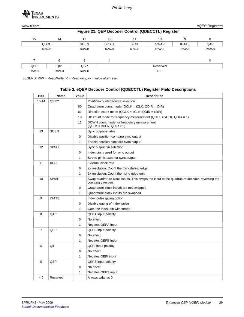
www.ti.com eQEP RegistersFigure 21. QEP Decoder Control (QDECCTL) Register
15 14 13 12 11 10 9 8QSRC SOEN SPSEL XCR SWAP IGATE QAPR/W-0 R/W-0 R/W-0 R/W-0 R/W-0 R/W-0 R/W-0
7 6 5 4 0
QBP QIP QSP ReservedR/W-0 R/W-0 R/W-0 R-0
LEGEND: R/W = Read/Write; R = Read only; -n = value after reset
Table 3. eQEP Decoder Control (QDECCTL) Register Field DescriptionsBits Name Value Description
15-14 QSRC Position-counter source selection00 Quadrature count mode (QCLK = iCLK, QDIR = iDIR)01 Direction-count mode (QCLK = xCLK, QDIR = xDIR)10 UP count mode for frequency measurement (QCLK = xCLK, QDIR = 1)11 DOWN count mode for frequency measurement
(QCLK = xCLK, QDIR = 0)13 SOEN Sync output-enable
0 Disable position-compare sync output1 Enable position-compare sync output
12 SPSEL Sync output pin selection0 Index pin is used for sync output1 Strobe pin is used for sync output
11 XCR External clock rate0 2x resolution: Count the rising/falling edge1 1x resolution: Count the rising edge only
10 SWAP Swap quadrature clock inputs. This swaps the input to the quadrature decoder, reversing thecounting direction.
0 Quadrature-clock inputs are not swapped1 Quadrature-clock inputs are swapped
9 IGATE Index pulse gating option0 Disable gating of Index pulse1 Gate the index pin with strobe
8 QAP QEPA input polarity0 No effect1 Negates QEPA input
7 QBP QEPB input polarity0 No effect1 Negates QEPB input
6 QIP QEPI input polarity0 No effect1 Negates QEPI input
5 QSP QEPS input polarity0 No effect1 Negates QEPS input
4-0 Reserved Always write as 0
SPRUFK8–May 2009 Enhanced QEP (eQEP) Module 29Submit Documentation Feedback

Preliminary
eQEP Registers www.ti.com
Figure 22. eQEP Control (QEPCTL) Register
15 14 13 12 11 10 9 8 7 6 5 4 3 2 1 0FREE, SOFT PCRM SEI IEI SWI SEL IEL QPEN QCLM UTE WDE
R/W-0 R/W-0 R/W-0 R/W-0 R/W-0 R/W-0 R/W-0 R/W-0 R/W-0 R/W-0 R/W-0
LEGEND: R/W = Read/Write; R = Read only; -n = value after reset
Table 4. eQEP Control (QEPCTL) Register Field DescriptionsBits Name Value Description
15-14 FREE, Emulation Control BitsSOFT QPOSCNT behavior
00 Position counter stops immediately on emulation suspend01 Position counter continues to count until the rollover1x Position counter is unaffected by emulation suspend
QWDTMR behavior00 Watchdog counter stops immediately01 Watchdog counter counts until WD period match roll over1x Watchdog counter is unaffected by emulation suspend
QUTMR behavior00 Unit timer stops immediately01 Unit timer counts until period rollover1x Unit timer is unaffected by emulation suspend
QCTMR behavior00 Capture Timer stops immediately01 Capture Timer counts until next unit period event1x Capture Timer is unaffected by emulation suspend
13-12 PCRM Position counter reset mode00 Position counter reset on an index event01 Position counter reset on the maximum position10 Position counter reset on the first index event11 Position counter reset on a unit time event
11-10 SEI Strobe event initialization of position counter00 Does nothing (action disabled)01 Does nothing (action disabled)10 Initializes the position counter on rising edge of the QEPS signal11 Clockwise Direction:
Initializes the position counter on the rising edge of QEPS strobeCounter Clockwise Direction:Initializes the position counter on the falling edge of QEPS strobe
9-8 IEI Index event initialization of position counter00 Do nothing (action disabled)01 Do nothing (action disabled)10 Initializes the position counter on the rising edge of the QEPI signal (QPOSCNT =
QPOSINIT)11 Initializes the position counter on the falling edge of QEPI signal (QPOSCNT = QPOSINIT)
7 SWI Software initialization of position counter0 Do nothing (action disabled)1 Initialize position counter (QPOSCNT=QPOSINIT). This bit is not cleared automatically
30 Enhanced QEP (eQEP) Module SPRUFK8–May 2009Submit Documentation Feedback
Preliminary
www.ti.com eQEP Registers
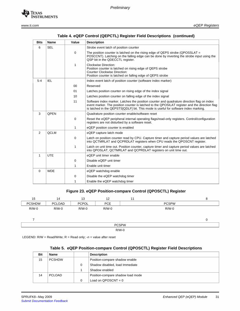
Table 4. eQEP Control (QEPCTL) Register Field Descriptions (continued)Bits Name Value Description
6 SEL Strobe event latch of position counter0 The position counter is latched on the rising edge of QEPS strobe (QPOSSLAT =
POSCCNT). Latching on the falling edge can be done by inverting the strobe input using theQSP bit in the QDECCTL register.
1 Clockwise Direction:Position counter is latched on rising edge of QEPS strobeCounter Clockwise Direction:Position counter is latched on falling edge of QEPS strobe
5-4 IEL Index event latch of position counter (software index marker)00 Reserved01 Latches position counter on rising edge of the index signal10 Latches position counter on falling edge of the index signal11 Software index marker. Latches the position counter and quadrature direction flag on index
event marker. The position counter is latched to the QPOSILAT register and the direction flagis latched in the QEPSTS[QDLF] bit. This mode is useful for software index marking.
3 QPEN Quadrature position counter enable/software reset0 Reset the eQEP peripheral internal operating flags/read-only registers. Control/configuration
registers are not disturbed by a software reset.1 eQEP position counter is enabled
2 QCLM eQEP capture latch mode0 Latch on position counter read by CPU. Capture timer and capture period values are latched
into QCTMRLAT and QCPRDLAT registers when CPU reads the QPOSCNT register.1 Latch on unit time out. Position counter, capture timer and capture period values are latched
into QPOSLAT, QCTMRLAT and QCPRDLAT registers on unit time out.1 UTE eQEP unit timer enable
0 Disable eQEP unit timer1 Enable unit timer
0 WDE eQEP watchdog enable0 Disable the eQEP watchdog timer1 Enable the eQEP watchdog timer
Figure 23. eQEP Position-compare Control (QPOSCTL) Register
15 14 13 12 11 8PCSHDW PCLOAD PCPOL PCE PCSPW
R/W-0 R/W-0 R/W-0 R/W-0 R/W-0
7 0
PCSPWR/W-0
LEGEND: R/W = Read/Write; R = Read only; -n = value after reset
Table 5. eQEP Position-compare Control (QPOSCTL) Register Field DescriptionsBit Name Description15 PCSHDW Position-compare shadow enable
0 Shadow disabled, load Immediate1 Shadow enabled
14 PCLOAD Position-compare shadow load mode0 Load on QPOSCNT = 0
SPRUFK8–May 2009 Enhanced QEP (eQEP) Module 31Submit Documentation Feedback
Preliminary
eQEP Registers www.ti.com
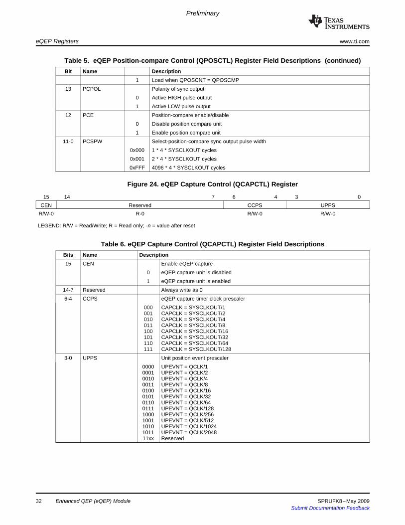
Table 5. eQEP Position-compare Control (QPOSCTL) Register Field Descriptions (continued)Bit Name Description
1 Load when QPOSCNT = QPOSCMP13 PCPOL Polarity of sync output
0 Active HIGH pulse output1 Active LOW pulse output
12 PCE Position-compare enable/disable0 Disable position compare unit1 Enable position compare unit
11-0 PCSPW Select-position-compare sync output pulse width0x000 1 * 4 * SYSCLKOUT cycles0x001 2 * 4 * SYSCLKOUT cycles0xFFF 4096 * 4 * SYSCLKOUT cycles
Figure 24. eQEP Capture Control (QCAPCTL) Register
15 14 7 6 4 3 0CEN Reserved CCPS UPPS
R/W-0 R-0 R/W-0 R/W-0
LEGEND: R/W = Read/Write; R = Read only; -n = value after reset
Table 6. eQEP Capture Control (QCAPCTL) Register Field DescriptionsBits Name Description15 CEN Enable eQEP capture
0 eQEP capture unit is disabled1 eQEP capture unit is enabled
14-7 Reserved Always write as 06-4 CCPS eQEP capture timer clock prescaler
000 CAPCLK = SYSCLKOUT/1001 CAPCLK = SYSCLKOUT/2010 CAPCLK = SYSCLKOUT/4011 CAPCLK = SYSCLKOUT/8100 CAPCLK = SYSCLKOUT/16101 CAPCLK = SYSCLKOUT/32110 CAPCLK = SYSCLKOUT/64111 CAPCLK = SYSCLKOUT/128
3-0 UPPS Unit position event prescaler0000 UPEVNT = QCLK/10001 UPEVNT = QCLK/20010 UPEVNT = QCLK/40011 UPEVNT = QCLK/80100 UPEVNT = QCLK/160101 UPEVNT = QCLK/320110 UPEVNT = QCLK/640111 UPEVNT = QCLK/1281000 UPEVNT = QCLK/2561001 UPEVNT = QCLK/5121010 UPEVNT = QCLK/10241011 UPEVNT = QCLK/204811xx Reserved
Enhanced QEP (eQEP) Module32 SPRUFK8–May 2009Submit Documentation Feedback

Preliminary
www.ti.com eQEP Registers
Figure 25. eQEP Position Counter (QPOSCNT) Register
31 0QPOSCNT
R/W-0
LEGEND: R/W = Read/Write; R = Read only; -n = value after reset
Table 7. eQEP Position Counter (QPOSCNT) Register Field DescriptionsBits Name Description31-0 QPOSCNT This 32-bit position counter register counts up/down on every eQEP pulse based on direction
input. This counter acts as a position integrator whose count value is proportional to positionfrom a give reference point.
Figure 26. eQEP Position Counter Initialization (QPOSINIT) Register
31 0QPOSINIT
R/W-0
LEGEND: R/W = Read/Write; R = Read only; -n = value after reset
Table 8. eQEP Position Counter Initialization (QPOSINIT) Register Field DescriptionsBits Name Description31-0 QPOSINIT This register contains the position value that is used to initialize the position counter based on
external strobe or index event. The position counter can be initialized through software.
Figure 27. eQEP Maximum Position Count Register (QPOSMAX) Register
31 0QPOSMAX
R/W-0
LEGEND: R/W = Read/Write; R = Read only; -n = value after reset
Table 9. eQEP Maximum Position Count (QPOSMAX) Register Field DescriptionsBits Name Description31-0 QPOSMAX This register contains the maximum position counter value.
Figure 28. eQEP Position-compare (QPOSCMP) Register
31 0QPOSCMP
R/W-0
LEGEND: R/W = Read/Write; R = Read only; -n = value after reset
SPRUFK8–May 2009 Enhanced QEP (eQEP) Module 33Submit Documentation Feedback
Preliminary
eQEP Registers www.ti.com
Table 10. eQEP Position-compare (QPOSCMP) Register Field DescriptionsBits Name Description31-0 QPOSCMP The position-compare value in this register is compared with the position counter (QPOSCNT) to
generate sync output and/or interrupt on compare match.
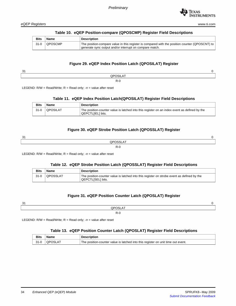
Figure 29. eQEP Index Position Latch (QPOSILAT) Register
31 0QPOSILAT
R-0
LEGEND: R/W = Read/Write; R = Read only; -n = value after reset
Table 11. eQEP Index Position Latch(QPOSILAT) Register Field DescriptionsBits Name Description31-0 QPOSILAT The position-counter value is latched into this register on an index event as defined by the
QEPCTL[IEL] bits.
Figure 30. eQEP Strobe Position Latch (QPOSSLAT) Register
31 0QPOSSLAT
R-0
LEGEND: R/W = Read/Write; R = Read only; -n = value after reset
Table 12. eQEP Strobe Position Latch (QPOSSLAT) Register Field DescriptionsBits Name Description31-0 QPOSSLAT The position-counter value is latched into this register on strobe event as defined by the
QEPCTL[SEL] bits.
Figure 31. eQEP Position Counter Latch (QPOSLAT) Register
31 0QPOSLAT
R-0
LEGEND: R/W = Read/Write; R = Read only; -n = value after reset
Table 13. eQEP Position Counter Latch (QPOSLAT) Register Field DescriptionsBits Name Description31-0 QPOSLAT The position-counter value is latched into this register on unit time out event.
Enhanced QEP (eQEP) Module34 SPRUFK8–May 2009Submit Documentation Feedback
Preliminary
www.ti.com eQEP Registers
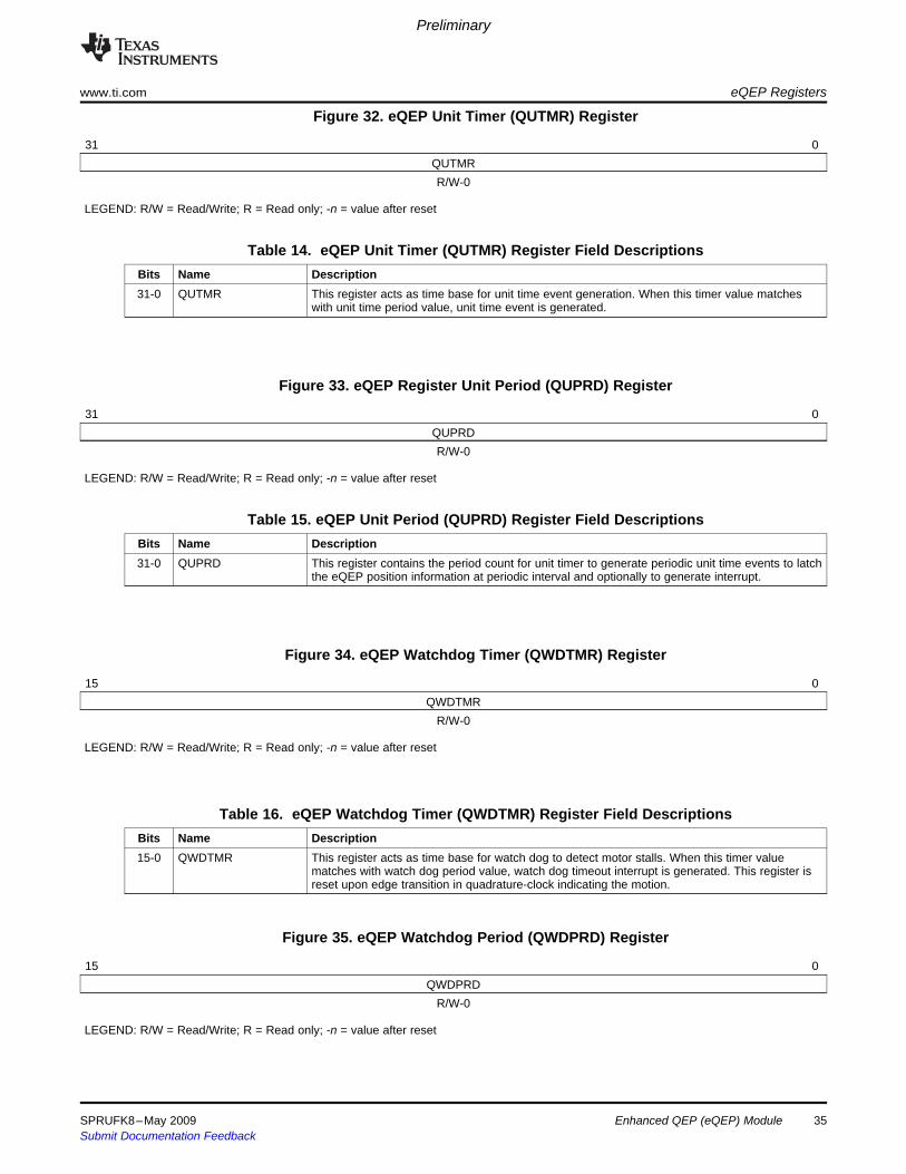
Figure 32. eQEP Unit Timer (QUTMR) Register
31 0QUTMRR/W-0
LEGEND: R/W = Read/Write; R = Read only; -n = value after reset
Table 14. eQEP Unit Timer (QUTMR) Register Field DescriptionsBits Name Description31-0 QUTMR This register acts as time base for unit time event generation. When this timer value matches
with unit time period value, unit time event is generated.
Figure 33. eQEP Register Unit Period (QUPRD) Register
31 0QUPRDR/W-0
LEGEND: R/W = Read/Write; R = Read only; -n = value after reset
Table 15. eQEP Unit Period (QUPRD) Register Field DescriptionsBits Name Description31-0 QUPRD This register contains the period count for unit timer to generate periodic unit time events to latch
the eQEP position information at periodic interval and optionally to generate interrupt.
Figure 34. eQEP Watchdog Timer (QWDTMR) Register
15 0QWDTMR
R/W-0
LEGEND: R/W = Read/Write; R = Read only; -n = value after reset
Table 16. eQEP Watchdog Timer (QWDTMR) Register Field DescriptionsBits Name Description15-0 QWDTMR This register acts as time base for watch dog to detect motor stalls. When this timer value
matches with watch dog period value, watch dog timeout interrupt is generated. This register isreset upon edge transition in quadrature-clock indicating the motion.
Figure 35. eQEP Watchdog Period (QWDPRD) Register
15 0QWDPRD
R/W-0
LEGEND: R/W = Read/Write; R = Read only; -n = value after reset
SPRUFK8–May 2009 Enhanced QEP (eQEP) Module 35Submit Documentation Feedback
Preliminary
eQEP Registers www.ti.com
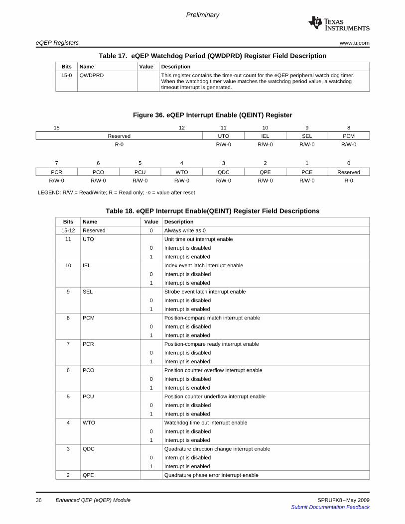
Table 17. eQEP Watchdog Period (QWDPRD) Register Field DescriptionBits Name Value Description15-0 QWDPRD This register contains the time-out count for the eQEP peripheral watch dog timer.
When the watchdog timer value matches the watchdog period value, a watchdogtimeout interrupt is generated.
Figure 36. eQEP Interrupt Enable (QEINT) Register
15 12 11 10 9 8Reserved UTO IEL SEL PCM
R-0 R/W-0 R/W-0 R/W-0 R/W-0
7 6 5 4 3 2 1 0
PCR PCO PCU WTO QDC QPE PCE ReservedR/W-0 R/W-0 R/W-0 R/W-0 R/W-0 R/W-0 R/W-0 R-0
LEGEND: R/W = Read/Write; R = Read only; -n = value after reset
Table 18. eQEP Interrupt Enable(QEINT) Register Field DescriptionsBits Name Value Description
15-12 Reserved 0 Always write as 011 UTO Unit time out interrupt enable
0 Interrupt is disabled1 Interrupt is enabled
10 IEL Index event latch interrupt enable0 Interrupt is disabled1 Interrupt is enabled
9 SEL Strobe event latch interrupt enable0 Interrupt is disabled1 Interrupt is enabled
8 PCM Position-compare match interrupt enable0 Interrupt is disabled1 Interrupt is enabled
7 PCR Position-compare ready interrupt enable0 Interrupt is disabled1 Interrupt is enabled
6 PCO Position counter overflow interrupt enable0 Interrupt is disabled1 Interrupt is enabled
5 PCU Position counter underflow interrupt enable0 Interrupt is disabled1 Interrupt is enabled
4 WTO Watchdog time out interrupt enable0 Interrupt is disabled1 Interrupt is enabled
3 QDC Quadrature direction change interrupt enable0 Interrupt is disabled1 Interrupt is enabled
2 QPE Quadrature phase error interrupt enable
36 Enhanced QEP (eQEP) Module SPRUFK8–May 2009Submit Documentation Feedback
Preliminary
www.ti.com eQEP Registers
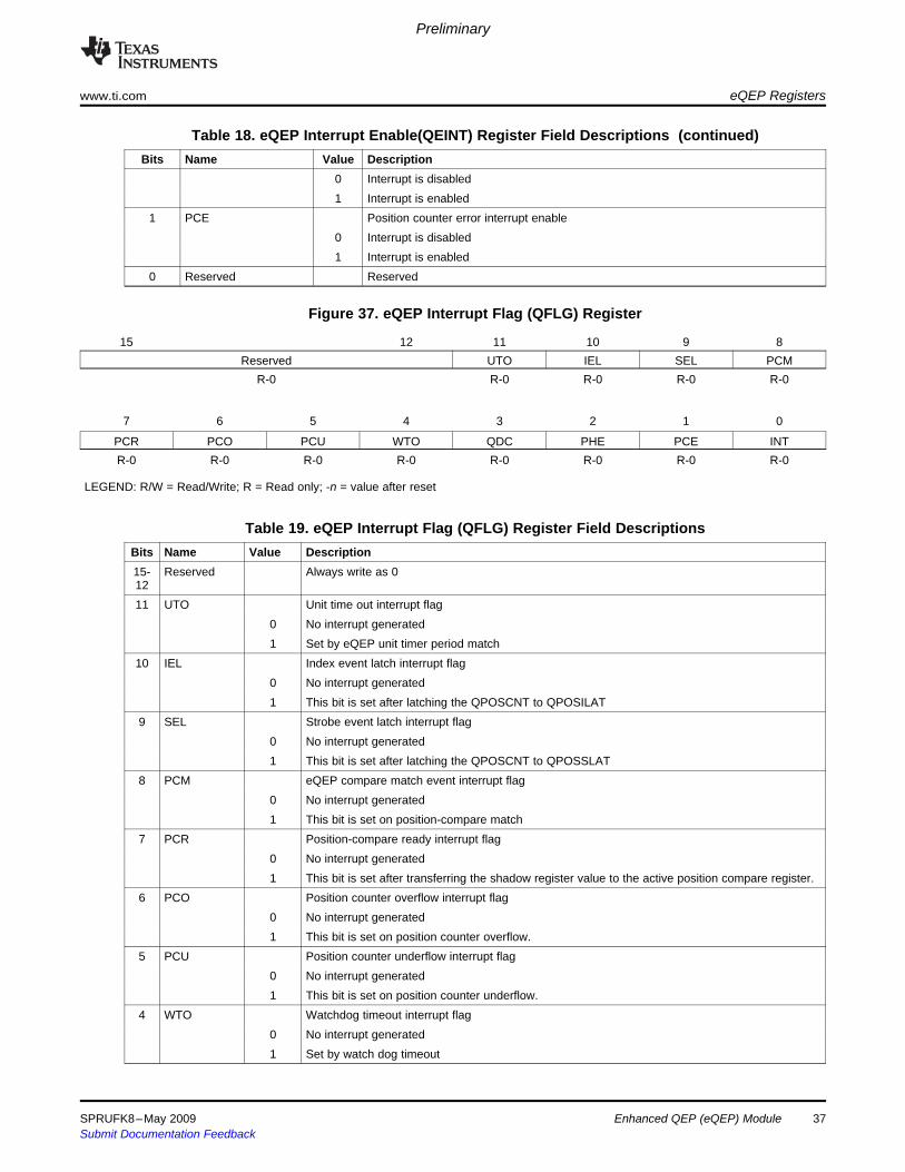
Table 18. eQEP Interrupt Enable(QEINT) Register Field Descriptions (continued)Bits Name Value Description
0 Interrupt is disabled1 Interrupt is enabled
1 PCE Position counter error interrupt enable0 Interrupt is disabled1 Interrupt is enabled
0 Reserved Reserved
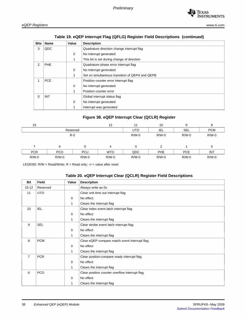
Figure 37. eQEP Interrupt Flag (QFLG) Register
15 12 11 10 9 8Reserved UTO IEL SEL PCM
R-0 R-0 R-0 R-0 R-0
7 6 5 4 3 2 1 0
PCR PCO PCU WTO QDC PHE PCE INTR-0 R-0 R-0 R-0 R-0 R-0 R-0 R-0
LEGEND: R/W = Read/Write; R = Read only; -n = value after reset
Table 19. eQEP Interrupt Flag (QFLG) Register Field DescriptionsBits Name Value Description15- Reserved Always write as 01211 UTO Unit time out interrupt flag
0 No interrupt generated1 Set by eQEP unit timer period match
10 IEL Index event latch interrupt flag0 No interrupt generated1 This bit is set after latching the QPOSCNT to QPOSILAT
9 SEL Strobe event latch interrupt flag0 No interrupt generated1 This bit is set after latching the QPOSCNT to QPOSSLAT
8 PCM eQEP compare match event interrupt flag0 No interrupt generated1 This bit is set on position-compare match
7 PCR Position-compare ready interrupt flag0 No interrupt generated1 This bit is set after transferring the shadow register value to the active position compare register.
6 PCO Position counter overflow interrupt flag0 No interrupt generated1 This bit is set on position counter overflow.
5 PCU Position counter underflow interrupt flag0 No interrupt generated1 This bit is set on position counter underflow.
4 WTO Watchdog timeout interrupt flag0 No interrupt generated1 Set by watch dog timeout
SPRUFK8–May 2009 Enhanced QEP (eQEP) Module 37Submit Documentation Feedback
Preliminary
eQEP Registers www.ti.com
Table 19. eQEP Interrupt Flag (QFLG) Register Field Descriptions (continued)Bits Name Value Description
3 QDC Quadrature direction change interrupt flag0 No interrupt generated1 This bit is set during change of direction
2 PHE Quadrature phase error interrupt flag0 No interrupt generated1 Set on simultaneous transition of QEPA and QEPB
1 PCE Position counter error interrupt flag0 No interrupt generated1 Position counter error
0 INT Global interrupt status flag0 No interrupt generated1 Interrupt was generated
Figure 38. eQEP Interrupt Clear (QCLR) Register
15 12 11 10 9 8Reserved UTO IEL SEL PCM
R-0 R/W-0 R/W-0 R/W-0 R/W-0
7 6 5 4 3 2 1 0
PCR PCO PCU WTO QDC PHE PCE INTR/W-0 R/W-0 R/W-0 R/W-0 R/W-0 R/W-0 R/W-0 R/W-0
LEGEND: R/W = Read/Write; R = Read only; -n = value after reset
Table 20. eQEP Interrupt Clear (QCLR) Register Field DescriptionsBit Field Value Description
15-12 Reserved Always write as 0s11 UTO Clear unit time out interrupt flag
0 No effect1 Clears the interrupt flag
10 IEL Clear index event latch interrupt flag0 No effect1 Clears the interrupt flag
9 SEL Clear strobe event latch interrupt flag0 No effect1 Clears the interrupt flag
8 PCM Clear eQEP compare match event interrupt flag0 No effect1 Clears the interrupt flag
7 PCR Clear position-compare ready interrupt flag0 No effect1 Clears the interrupt flag
6 PCO Clear position counter overflow interrupt flag0 No effect1 Clears the interrupt flag
38 Enhanced QEP (eQEP) Module SPRUFK8–May 2009Submit Documentation Feedback
Preliminary
www.ti.com eQEP Registers
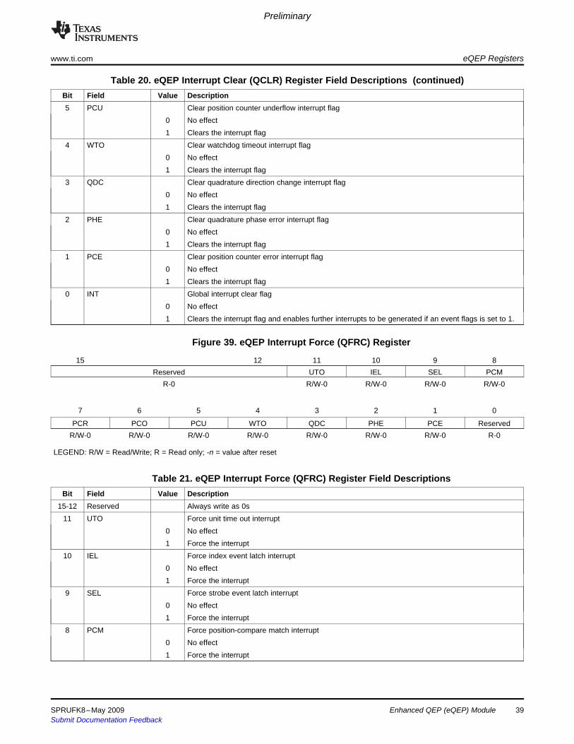
Table 20. eQEP Interrupt Clear (QCLR) Register Field Descriptions (continued)Bit Field Value Description5 PCU Clear position counter underflow interrupt flag
0 No effect1 Clears the interrupt flag
4 WTO Clear watchdog timeout interrupt flag0 No effect1 Clears the interrupt flag
3 QDC Clear quadrature direction change interrupt flag0 No effect1 Clears the interrupt flag
2 PHE Clear quadrature phase error interrupt flag0 No effect1 Clears the interrupt flag
1 PCE Clear position counter error interrupt flag0 No effect1 Clears the interrupt flag
0 INT Global interrupt clear flag0 No effect1 Clears the interrupt flag and enables further interrupts to be generated if an event flags is set to 1.
Figure 39. eQEP Interrupt Force (QFRC) Register
15 12 11 10 9 8Reserved UTO IEL SEL PCM
R-0 R/W-0 R/W-0 R/W-0 R/W-0
7 6 5 4 3 2 1 0
PCR PCO PCU WTO QDC PHE PCE ReservedR/W-0 R/W-0 R/W-0 R/W-0 R/W-0 R/W-0 R/W-0 R-0
LEGEND: R/W = Read/Write; R = Read only; -n = value after reset
Table 21. eQEP Interrupt Force (QFRC) Register Field DescriptionsBit Field Value Description
15-12 Reserved Always write as 0s11 UTO Force unit time out interrupt
0 No effect1 Force the interrupt
10 IEL Force index event latch interrupt0 No effect1 Force the interrupt
9 SEL Force strobe event latch interrupt0 No effect1 Force the interrupt
8 PCM Force position-compare match interrupt0 No effect1 Force the interrupt
SPRUFK8–May 2009 Enhanced QEP (eQEP) Module 39Submit Documentation Feedback
Preliminary
eQEP Registers www.ti.com
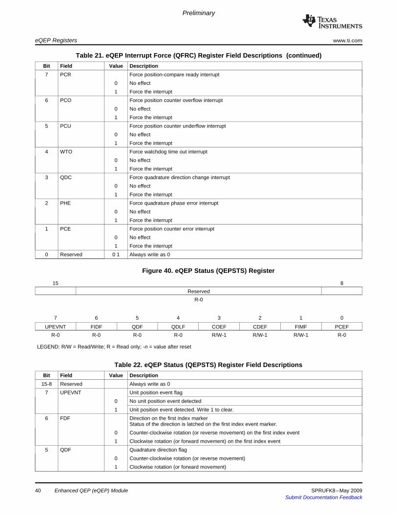
Table 21. eQEP Interrupt Force (QFRC) Register Field Descriptions (continued)Bit Field Value Description7 PCR Force position-compare ready interrupt
0 No effect1 Force the interrupt
6 PCO Force position counter overflow interrupt0 No effect1 Force the interrupt
5 PCU Force position counter underflow interrupt0 No effect1 Force the interrupt
4 WTO Force watchdog time out interrupt0 No effect1 Force the interrupt
3 QDC Force quadrature direction change interrupt0 No effect1 Force the interrupt
2 PHE Force quadrature phase error interrupt0 No effect1 Force the interrupt
1 PCE Force position counter error interrupt0 No effect1 Force the interrupt
0 Reserved 0 1 Always write as 0
Figure 40. eQEP Status (QEPSTS) Register
15 8Reserved
R-0
7 6 5 4 3 2 1 0
UPEVNT FIDF QDF QDLF COEF CDEF FIMF PCEFR-0 R-0 R-0 R-0 R/W-1 R/W-1 R/W-1 R-0
LEGEND: R/W = Read/Write; R = Read only; -n = value after reset
Table 22. eQEP Status (QEPSTS) Register Field DescriptionsBit Field Value Description
15-8 Reserved Always write as 07 UPEVNT Unit position event flag
0 No unit position event detected1 Unit position event detected. Write 1 to clear.
6 FDF Direction on the first index markerStatus of the direction is latched on the first index event marker.
0 Counter-clockwise rotation (or reverse movement) on the first index event1 Clockwise rotation (or forward movement) on the first index event
5 QDF Quadrature direction flag0 Counter-clockwise rotation (or reverse movement)1 Clockwise rotation (or forward movement)
40 Enhanced QEP (eQEP) Module SPRUFK8–May 2009Submit Documentation Feedback
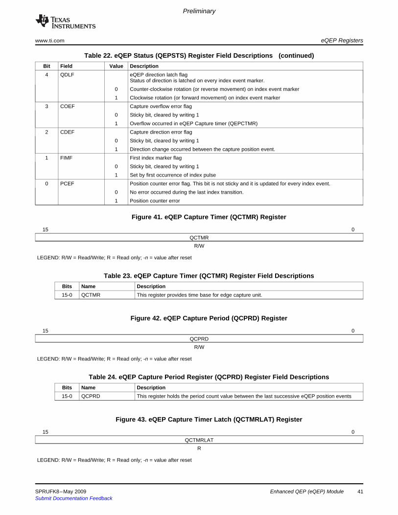
Preliminary
www.ti.com eQEP Registers
Table 22. eQEP Status (QEPSTS) Register Field Descriptions (continued)Bit Field Value Description4 QDLF eQEP direction latch flag
Status of direction is latched on every index event marker.0 Counter-clockwise rotation (or reverse movement) on index event marker1 Clockwise rotation (or forward movement) on index event marker
3 COEF Capture overflow error flag0 Sticky bit, cleared by writing 11 Overflow occurred in eQEP Capture timer (QEPCTMR)
2 CDEF Capture direction error flag0 Sticky bit, cleared by writing 11 Direction change occurred between the capture position event.
1 FIMF First index marker flag0 Sticky bit, cleared by writing 11 Set by first occurrence of index pulse
0 PCEF Position counter error flag. This bit is not sticky and it is updated for every index event.0 No error occurred during the last index transition.1 Position counter error
Figure 41. eQEP Capture Timer (QCTMR) Register
15 0QCTMR
R/W
LEGEND: R/W = Read/Write; R = Read only; -n = value after reset
Table 23. eQEP Capture Timer (QCTMR) Register Field DescriptionsBits Name Description15-0 QCTMR This register provides time base for edge capture unit.
Figure 42. eQEP Capture Period (QCPRD) Register
15 0QCPRD
R/W
LEGEND: R/W = Read/Write; R = Read only; -n = value after reset
Table 24. eQEP Capture Period Register (QCPRD) Register Field DescriptionsBits Name Description15-0 QCPRD This register holds the period count value between the last successive eQEP position events
Figure 43. eQEP Capture Timer Latch (QCTMRLAT) Register
15 0QCTMRLAT
R
LEGEND: R/W = Read/Write; R = Read only; -n = value after reset
SPRUFK8–May 2009 Enhanced QEP (eQEP) Module 41Submit Documentation Feedback
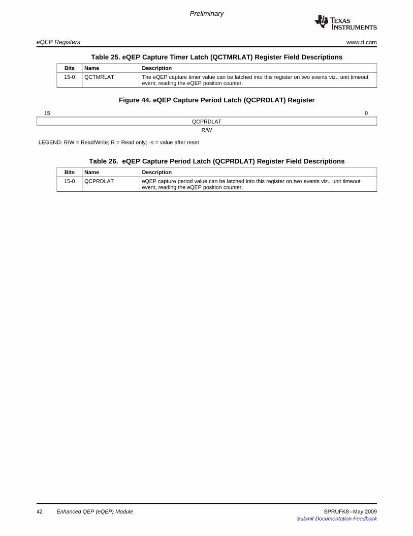
Preliminary
eQEP Registers www.ti.com
Table 25. eQEP Capture Timer Latch (QCTMRLAT) Register Field DescriptionsBits Name Description15-0 QCTMRLAT The eQEP capture timer value can be latched into this register on two events viz., unit timeout
event, reading the eQEP position counter.
Figure 44. eQEP Capture Period Latch (QCPRDLAT) Register
15 0QCPRDLAT
R/W
LEGEND: R/W = Read/Write; R = Read only; -n = value after reset
Table 26. eQEP Capture Period Latch (QCPRDLAT) Register Field DescriptionsBits Name Description15-0 QCPRDLAT eQEP capture period value can be latched into this register on two events viz., unit timeout
event, reading the eQEP position counter.
Enhanced QEP (eQEP) Module42 SPRUFK8–May 2009Submit Documentation Feedback

IMPORTANT NOTICETexas Instruments Incorporated and its subsidiaries (TI) reserve the right to make corrections, modifications, enhancements, improvements,and other changes to its products and services at any time and to discontinue any product or service without notice. Customers shouldobtain the latest relevant information before placing orders and should verify that such information is current and complete. All products aresold subject to TI’s terms and conditions of sale supplied at the time of order acknowledgment.TI warrants performance of its hardware products to the specifications applicable at the time of sale in accordance with TI’s standardwarranty. Testing and other quality control techniques are used to the extent TI deems necessary to support this warranty. Except wheremandated by government requirements, testing of all parameters of each product is not necessarily performed.TI assumes no liability for applications assistance or customer product design. Customers are responsible for their products andapplications using TI components. To minimize the risks associated with customer products and applications, customers should provideadequate design and operating safeguards.TI does not warrant or represent that any license, either express or implied, is granted under any TI patent right, copyright, mask work right,or other TI intellectual property right relating to any combination, machine, or process in which TI products or services are used. Informationpublished by TI regarding third-party products or services does not constitute a license from TI to use such products or services or awarranty or endorsement thereof. Use of such information may require a license from a third party under the patents or other intellectualproperty of the third party, or a license from TI under the patents or other intellectual property of TI.Reproduction of TI information in TI data books or data sheets is permissible only if reproduction is without alteration and is accompaniedby all associated warranties, conditions, limitations, and notices. Reproduction of this information with alteration is an unfair and deceptivebusiness practice. TI is not responsible or liable for such altered documentation. Information of third parties may be subject to additionalrestrictions.Resale of TI products or services with statements different from or beyond the parameters stated by TI for that product or service voids allexpress and any implied warranties for the associated TI product or service and is an unfair and deceptive business practice. TI is notresponsible or liable for any such statements.TI products are not authorized for use in safety-critical applications (such as life support) where a failure of the TI product would reasonablybe expected to cause severe personal injury or death, unless officers of the parties have executed an agreement specifically governingsuch use. Buyers represent that they have all necessary expertise in the safety and regulatory ramifications of their applications, andacknowledge and agree that they are solely responsible for all legal, regulatory and safety-related requirements concerning their productsand any use of TI products in such safety-critical applications, notwithstanding any applications-related information or support that may beprovided by TI. Further, Buyers must fully indemnify TI and its representatives against any damages arising out of the use of TI products insuch safety-critical applications.TI products are neither designed nor intended for use in military/aerospace applications or environments unless the TI products arespecifically designated by TI as military-grade or "enhanced plastic." Only products designated by TI as military-grade meet militaryspecifications. Buyers acknowledge and agree that any such use of TI products which TI has not designated as military-grade is solely atthe Buyer's risk, and that they are solely responsible for compliance with all legal and regulatory requirements in connection with such use.TI products are neither designed nor intended for use in automotive applications or environments unless the specific TI products aredesignated by TI as compliant with ISO/TS 16949 requirements. Buyers acknowledge and agree that, if they use any non-designatedproducts in automotive applications, TI will not be responsible for any failure to meet such requirements.Following are URLs where you can obtain information on other Texas Instruments products and application solutions:Products ApplicationsAmplifiers amplifier.ti.com Audio www.ti.com/audioData Converters dataconverter.ti.com Automotive www.ti.com/automotiveDLP® Products www.dlp.com Broadband www.ti.com/broadbandDSP dsp.ti.com Digital Control www.ti.com/digitalcontrolClocks and Timers www.ti.com/clocks Medical www.ti.com/medicalInterface interface.ti.com Military www.ti.com/militaryLogic logic.ti.com Optical Networking www.ti.com/opticalnetworkPower Mgmt power.ti.com Security www.ti.com/securityMicrocontrollers microcontroller.ti.com Telephony www.ti.com/telephonyRFID www.ti-rfid.com Video & Imaging www.ti.com/videoRF/IF and ZigBee® Solutions www.ti.com/lprf Wireless www.ti.com/wireless
Mailing Address: Texas Instruments, Post Office Box 655303, Dallas, Texas 75265Copyright © 2009, Texas Instruments Incorporated