Embed Size (px)
Citation preview

TM 9-2520-238-34
TECHNICAL MANUAL
DIRECT SUPPORT AND GENERAL SUPPORT MAINTENANCE MANUAL
FOR
RIGHT ANGLE DRIVE, COOLING FANM113A1 FOV, M113A2 FOV — 2990-00-712-1280
M113A3 FOV — 3010-01-318-5670
GEARCASE, TRANSFERM548, M548A1 — 2520-01-047-8613
SERVICE GEARCASE — 2520-01-087-0156M113A1 FOV — 2520-00-572-8605
M113A2 FOV WITH 100 AMP GENERATOR — 2520-01-061-5570M113A1 FOV, M113A2 FOV WITH 200 AMP GENERATOR — 2520-01-362-8589
DRIVE ASSEMBLY, FINALM113A2 FOV, M113A3 FOV — 2520-01-061-5766
M548, M548A1 — 2520-01-067-8933
DIFFERENTIAL, STEERING CONTROLM113A1 FOV, M113A2 FOV, M548, M548A1 — 2520-00-714-6135
BRAKE, SINGLE DISKM113 FOV, M548, M548A1 — 2530-00-088-9866
CYLINDER ASSEMBLY, HYDRAULIC BRAKEM113 FOV, M548, M548A1 — 2530-00-679-9169
SUPERSEDURE NOTICE — This manual supersedes TM 9-2520-238-34 dated September 1991, including all changes.
DISTRIBUTION STATEMENT A — Approved for public release; distribution is unlimited.
HEADQUARTERS, DEPARTMENT OF THE ARMY
31 MAY 2001


TM 9-2520-238-34
WARNING SUMMARY
WARNING SUMMARY
This list summarizes critical WARNINGs in this manual. They are repeated here to let you know how important they are.Study these WARNINGs carefully; they can save your life and the lives of personnel you work with.
WARNING
Air pressure in excess of 30 psi (207 kPa) can injure personnel. Do not direct pressurized air atyourself or others. Always wear goggles.
WARNING
Adhesive is flammable and can injure you. Keep it away from heat, sparks, and open flame.Avoid repeated or prolonged breathing of vapors. Avoid contact with your skin.
WARNING
Fire resistant hydraulic (FRH) fluid may contain Tricresyl Phosphate which, if taken internally,can produce paralysis. Hydraulic fluid may be absorbed through the skin. Wear long sleeves,gloves, goggles, and face shield. If FRH gets in eyes, wash them immediately and get medical aidimmediately. If FRH gets on skin, thoroughly wash with soap and water. Wash handsthoroughly prior to eating or smoking.
WARNING
Lifting or moving objects in excess of 70 pounds could injure you. Make sure to get an assistantor use a lifting device to move fog oil tank, armor, or other heavy objects.
a

TM 9-2520-238-34
WARNING SUMMARY (cont)
WARNING
Parts of the brake assembly may be coated with asbestos dust; breathing this dust can harmpersonnel. Use a filter mask approved for use against asbestos dust. Never use compressed airor dry brush to clean these assemblies. Use an industrial type vacuum cleaner with ahigh-efficiency filter system to remove dust. Use water and a soft bristle brush or cloth toremove dirt or mud.
FIRST AID
For artificial respiration and first aid information, see FM 21-11.
b

TM 9-2520-238-34
A/B
INSERT LATEST UPDATED PAGES / WORK PACKAGES. DESTROY SUPERSEDED DATA.
LIST OF EFFECTIVE PAGES / WORK PACKAGES
NOTE: Updates to all portions of this TM are indicated by a vertical bar in the outer margin of the page.
Dates of issue for original and updated pages / work packages are:
Original 0 (31 May 2001)
TOTAL NUMBER OF PAGES FOR FRONT AND REAR MATTER IS 28 AND TOTALNUMBER OF WORK PACKAGES IS 35 CONSISTING OF THE FOLLOWING:
Page / WP No. * ChangeNo.
Page / WP No. * ChangeNo.
Page / WP No. * ChangeNo.
Title 0a – b 0A/B 0
i – vii/viii blank 0WP 0001 00 – 0035 00 0
1 – 2 0DA 2028/Back 0Authentication 0
Blank 0Metric Chart 0Back Cover 0
* Zero in this column indicates an original page or work package.


TM 9-2520-238-34
HEADQUARTERSDEPARTMENT OF THE ARMY
WASHINGTON, D.C., 31 MAY 2001
TECHNICAL MANUAL
DIRECT SUPPORT AND GENERAL SUPPORT MAINTENANCE MANUAL
RIGHT ANGLE DRIVE, COOLING FANM113A1 FOV, M113A2 FOV — 2990-00-712-1280
M113A3 FOV — 3010-01-318-5670
GEARCASE, TRANSFERM548, M548A1 — 2520-01-047-8613
SERVICE GEARCASE — 2520-01-087-0156M113A1 FOV — 2520-00-572-8605
M113A2 FOV WITH 100 AMP GENERATOR — 2520-01-061-5570M113A1 FOV, M113A2 FOV WITH 200 AMP GENERATOR — 2520-01-362-8589
DRIVE ASSEMBLY, FINALM113A2 FOV, M113A3 FOV — 2520-01-061-5766
M548, M548A1 — 2520-01-067-8933
DIFFERENTIAL, STEERING CONTROLM113A1 FOV, M113A2 FOV, M548, M548A1 — 2520-00-714-6135
BRAKE, SINGLE DISKM113 FOV, M548, M548A1 — 2530-00-088-9866
CYLINDER ASSEMBLY, HYDRAULIC BRAKEM113 FOV, M548, M548A1 — 2530-00-679-9169
SUPERSEDURE NOTICE — This manual supersedes TM 9-2520-238-34 dated September 1991, including all changes.
DISTRIBUTION STATEMENT A — Approved for public release; distribution is unlimited.
i
. The
fax
number
is
DSN
793–0726
or Commercial (309) 782–0726.
lim.ymra.air@SBUP-HCET-MOCA
If you need a password, scroll down and click on “ACCESS REQUESTFORM”. The DA Form 2028 is located in the ONLINE FORMS PROCESSING section of the AEPS. Fill out theform and click on SUBMIT. Using this form on the AEPS will enable us to respond quicker to your commentsand better manage the DA Form 2028 program. You may also mail, fax, or email your letter, DA Form 2028 direct to: AMSTA-LC-CI/TECH PUBS, TACOM-RI, Rock Island Arsenal, Rock Island, IL 61299-7630
The email address is T
.lim.ymra.air.spea//:ptt
REPORTING ERRORS AND RECOMMENDING IMPROVEMENTS
You can help improve this manual. If you find any mistakes or if you know of a way to improve the procedures,please let us know. Submit your DA Form 2028 (Recommended Changes to Publications and Blank Forms),,through the Internet, on the Army Electronic Product Support (AEPS) website. The Internetaddress is h

TM 9-2520-238-34
TABLE OF CONTENTS
WP Sequence No.
WARNING SUMMARY
HOW TO USE THIS MANUAL
CHAPTER 1 — INTRODUCTORY INFORMATION WITH THEORY OF OPERATION
GENERAL INFORMATION..............................................................................................................................0001 00
EQUIPMENT DESCRIPTION AND DATA.......................................................................................................0002 00
REPAIR PARTS, SPECIAL TOOLS, TMDE, AND SUPPORT EQUIPMENT................................................0003 00
CHAPTER 2 — TROUBLESHOOTING PROCEDURES
INTRODUCTION TO HOW TO USE TROUBLESHOOTING........................................................................0004 00
MALFUNCTION/SYMPTOM INDEX WP.......................................................................................................0005 00
COOLING FAN RIGHT ANGLE DRIVE LEAKS OIL....................................................................................0006 00
COOLING FAN RIGHT ANGLE DRIVE BINDS OR MAKES GRINDING NOISE......................................0007 00
TRANSFER GEARCASE LEAKS OIL.............................................................................................................0008 00
DIFFERENTIAL MAKES EXCESSIVE NOISE OR VIBRATES WHILE TURNING...................................0009 00
DIFFERENTIAL MAKES EXCESSIVE NOISE OR VIBRATES WHILE MOVING.....................................0010 00
FINAL DRIVE BINDS OR MAKES GRINDING NOISE.................................................................................0011 00
FINAL DRIVE LEAKS OIL...............................................................................................................................0012 00
FINAL DRIVE HAS WATER INSIDE...............................................................................................................0013 00
CHAPTER 3 — DIRECT SUPPORT MAINTENANCE INSTRUCTIONS FOR PMCSINCLUDING LUBRICATION PROCEDURES
PREVENTIVE MAINTENANCE CHECKS AND SERVICES (PMCS), INCLUDINGLUBRICATION INSTRUCTIONS............................................................................................................0014 00
CHAPTER 4 — DIRECT SUPPORT MAINTENANCE INSTRUCTIONS FOR REPAIRCOOLING FAN RIGHT ANGLE DRIVES
REPAIR COOLING FAN RIGHT ANGLE DRIVES A AND B........................................................................0015 00
REPAIR COOLING FAN RIGHT ANGLE DRIVE C (M113A3 FOV ONLY).................................................0016 00
CHAPTER 5 — DIRECT SUPPORT MAINTENANCE INSTRUCTIONS FOR REPAIRTRANSFER GEARCASES
REPAIR TRANSFER GEARCASES A, B, AND C...........................................................................................0017 00
REPLACE TRANSFER GEARCASE A, B, OR C WITH SERVICE SPARE TRANSFERGEARCASE E...........................................................................................................................................0018 00
REPAIR TRANSFER GEARCASE F.................................................................................................................0019 00
CHAPTER 6 — DIRECT SUPPORT MAINTENANCE INSTRUCTIONS FOR REPAIR FINALDRIVE ASSEMBLIES
ii

TM 9-2520-238-34
TABLE OF CONTENTS (cont)WP Sequence No.
REPAIR FINAL DRIVE ASSEMBLIES A AND B...........................................................................................0020 00
CHAPTER 7 — MAINTENANCE INSTRUCTIONS FOR STEERING CONTROL DIFFERENTIAL
REPLACE STRAIGHT ADAPTER AND BRAKE SHOE ASSEMBLIES.......................................................0021 00
REPAIR BRAKE SHOE ASSEMBLIES............................................................................................................0022 00
REPLACE OUTPUT SHAFT ASSEMBLIES....................................................................................................0023 00
REPAIR OUTPUT SHAFT ASSEMBLIES........................................................................................................0024 00
REPLACE DIFFERENTIAL STEERING CONTROL ASSEMBLY.................................................................0025 00
REPAIR DIFFERENTIAL STEERING CONTROL ASSEMBLY....................................................................0026 00
REPLACE DIFFERENTIAL RIGHT ANGLE GEARBOX...............................................................................0027 00
REPAIR DIFFERENTIAL RIGHT ANGLE GEARBOX..................................................................................0028 00
REPAIR STEERING CONTROL DIFFERENTIAL HOUSING.......................................................................0029 00
CHAPTER 8 — DIRECT SUPPORT MAINTENANCE INSTRUCTIONS FOR REPAIRSINGLE DISK PIVOT STEER BRAKE AND HYDRAULIC MASTERBRAKE CYLINDER
REPAIR SINGLE DISK PIVOT STEER BRAKE ASSEMBLY........................................................................0030 00
REPAIR HYDRAULIC MASTER BRAKE CYLINDER..................................................................................0031 00
CHAPTER 9 — SUPPORTING INFORMATION
REFERENCES....................................................................................................................................................0032 00
COMMON TOOLS AND SUPPLEMENTS AND SPECIAL TOOLS/FIXTURES LIST................................0033 00
FABRICATED TOOLS.......................................................................................................................................0034 00
EXPENDABLE/DURABLE SUPPLIES AND MATERIALS LIST..................................................................0035 00
iii/iv blank


TM 9-2520-238-34
HOW TO USE THIS MANUAL
HOW TO USE THIS MANUAL
This manual tells you how to perform direct and general support maintenance for transfer gearcases, final drives, cooling fanright angle drives, steering differential control, single disk pivot brake and hydraulic brake master cylinder for the M113Family of Vehicles.
Before starting a task or procedure, read HOW TO USE THIS MANUAL and GENERAL MAINTENANCE PROCEDURES(WP 0014 00).
WHAT’S IN THE MANUAL — FRONT TO BACK
This TM supplement is divided into front and rear matter and Work Packages (WPs) for ease of use.
The WARNING SUMMARY section provides safety and first aid information. This section includes general warnings notfound in the TM text and a list of the most important detailed warnings extracted from the WPs. All of these warnings coverhazards that could kill or injure personnel.
The TABLE OF CONTENTS lists the WPs.
CHAPTER 1 covers general introductory information. The Equipment Description WP gives a brief description ofcomponents covered in this manual.
CHAPTER 2 covers troubleshooting procedures authorized at the DS/GS maintenance level.
CHAPTER 3 includes PMCS procedures.
CHAPTER 4 contains maintenance WPs for the cooling fan right angle drives.
CHAPTER 5 contains maintenance WPs for the transfer gearcases.
CHAPTER 6 contains maintenance WPs for the final drive assemblies.
CHAPTER 7 contains maintenance WPs for the steering control differential.
CHAPTER 8 contains maintenance WPs for the single disk pivot steer brake and the hydraulic master brake cylinder.
CHAPTER 9 contains supporting information for the TM which includes the following WPs:The REFERENCES WP lists references to be used by personnel in operating and maintaining the carrier.The COMMON TOOLS and SUPPLEMENTS and SPECIAL TOOLS/FIXTURES WP lists the tools used in the initial
setup.The FABRICATED TOOLS WP lists instructions for making tools authorized to be fabricated at DS or GS maintenance
levels.The EXPENDABLE/DURABLE SUPPLIES and MATERIALS lists the expendable supplies and materials used to
maintain or repair the carrier.
The INDEX is an alphabetical listing of all the tasks in the WPs of this TM. Each entry is cross-referenced to the WP numberand page number.
The back cover includes a METRIC CONVERSION CHART that can be used to convert U.S. customary measurements totheir metric equivalents. Measurements in this manual are given in U.S. customary unit with metric units in parentheses.
HOW TO USE THE WORK PACKAGES
How to find the WP you need
Pick a key word from the carrier part or system to be used during the WP. Look in the INDEX for this key word or the nameof the action you will perform. Turn to the page indicated.
The INDEX lists each WP under one or more headings.
How to read the WP
Be sure to read all warnings, cautions and notes. These are in all types of WPs. They help you avoid harm to yourself, otherpersonnel and equipment. They also tell you things you should know about the WP.
v

TM 9-2520-238-34
HOW TO USE THIS MANUAL (cont)
Before starting, get all tools, supplies, and personnel, listed on the setup page needed to do the WP. Be sure to read the WPbefore performing the maintenance. If any other WPs are referenced, you must go to the setup page for each of those WPs tofind out what tools, parts, and materials will be needed.
Start with step 1 and do each step in given order.
Look at the illustrations. These show you what to look for when reading a maintenance WP.
Maintenance Instructions WPs
Doing maintenance WPs will keep the carrier in shape to operate. Maintenance WPs are used to present maintenanceinstructions. Each maintenance WP details steps which you need to perform. If the carrier and parts need maintenance that isnot included in any WP in the manual, report this to your supervisor.
Read the INITIAL SETUP section carefully before you start a WP. Get the tools and supplies listed and the personnel neededto perform the WP. Be sure that the equipment is in the condition required.
DEFINITION OF WP TERMS
WARNINGS, CAUTIONS, AND NOTES
Be sure to read all warnings and cautions in the WP. Ignoring a warning could cause death or injury to yourself or otherpersonnel. Ignoring a caution could cause damage to equipment. Notes contain facts to make the WP easier. Warnings,cautions, and notes always appear just above the WP step to which they apply.
WARNINGS Call attention to things that could kill or injure personnel. Warnings are also listedin the Warning Summary section (page a).
CAUTIONS Call attention to actions or materials that could damage equipment.
NOTES Contain important facts to make the procedure easier.
HELPER
Helpers are needed for WPs that require more that one person such as lifting heavy objects or acting as an observer.
If a helper is needed to perform a procedure, the INITIAL SETUP will list “Helper” under the PERSONNEL REQUIREDheading.
If helper assists with a step, the step will include: “Have helper assist”.
If a helper performs the action alone, the step will start with “HELPER”.
REFERENCES
References within a WP refer to a different manual or to another WP in the same manual. A step in one WP may be acomplete WP someplace else. Below is an example of a reference step from the WP: REPAIR BRAKE SHOE ASSEMBLIES.
Example: Check wear limits and clearances of parts, (WP 0021 00).
The tools needed to do the task will be listed in that task.
MATERIALS/PARTS
For all WPs, the following comments apply:Parts which are listed on the setup page will be referred to as “new” in the WP setup when installed.Examples are: “locknuts”, “lockwashers”, “cotter pins”, and some “gaskets”.These and other new parts are listed under MATERIAL/PARTS in the initial set up.
GENERAL MAINTENANCE
Cleaning, inspecting, checking for leaks, and similar procedures which apply to most WPs are found in the GENERALMAINTENANCE PROCEDURES (WP 0014 00). Use these steps to clean and inspect any part being removed, repaired, orinstalled. Special cleaning will be covered in the WP step. Below is a step that would require general cleaning.
vi
TM 9-2520-238-34
HOW TO USE THIS MANUAL (cont)
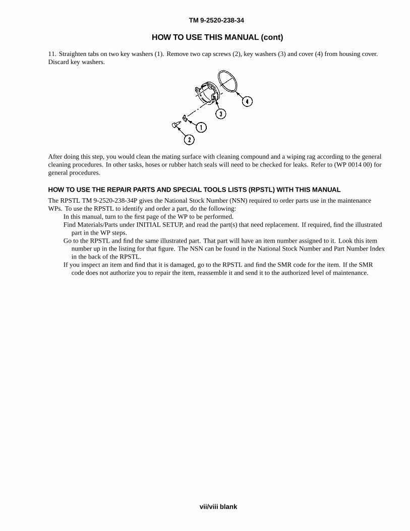
11. Straighten tabs on two key washers (1). Remove two cap screws (2), key washers (3) and cover (4) from housing cover.Discard key washers.
After doing this step, you would clean the mating surface with cleaning compound and a wiping rag according to the generalcleaning procedures. In other tasks, hoses or rubber hatch seals will need to be checked for leaks. Refer to (WP 0014 00) forgeneral procedures.
HOW TO USE THE REPAIR PARTS AND SPECIAL TOOLS LISTS (RPSTL) WITH THIS MANUAL
The RPSTL TM 9-2520-238-34P gives the National Stock Number (NSN) required to order parts use in the maintenanceWPs. To use the RPSTL to identify and order a part, do the following:
In this manual, turn to the first page of the WP to be performed.Find Materials/Parts under INITIAL SETUP, and read the part(s) that need replacement. If required, find the illustrated
part in the WP steps.Go to the RPSTL and find the same illustrated part. That part will have an item number assigned to it. Look this item
number up in the listing for that figure. The NSN can be found in the National Stock Number and Part Number Indexin the back of the RPSTL.
If you inspect an item and find that it is damaged, go to the RPSTL and find the SMR code for the item. If the SMRcode does not authorize you to repair the item, reassemble it and send it to the authorized level of maintenance.
vii/viii blank


TM 9-2520-238-34
CHAPTER 1
INTRODUCTORY INFORMATION WITH THEORY OF OPERATION
WORK PACKAGE INDEX
Title Sequence No.
GENERAL INFORMATION.............................................................................................................................................0001 00
EQUIPMENT DESCRIPTION AND DATA.....................................................................................................................0002 00
REPAIR PARTS, SPECIAL TOOLS, TMDE, AND SUPPORT EQUIPMENT...............................................................0003 00


TM 9-2520-238-34
GENERAL INFORMATION 0001 00
SCOPE
Type of Manual: Direct and General Support Maintenance
Model Number and Equipment Name:
Table 1. TABLE 1–1: COMPONENTS COVERED AND END ITEM APPLICATION
ComponentAlpha
SymbolNSN Part No. (CAGE)
End Item and TMReference
Gearcase,Transfer
A 2520-00-572-860510932770(19207)
M106A1, M113A1,M125A1, M132A1,M577A1 (TM9-2300-257 series).Replaced2520-00-771-8377.
Gearcase,Transfer
B 2520-01-061-557012253625(19207)
M106A2, M113A1,M113A2, M125A1,M125A2, M577A1,M577A2, M901A1,M981, M1059, M1064,M1068 (TM 9-2350-261series) (Carriers with100 ampere generators).
Gearcase,Transfer
C 2520-01-362-858912349527(19207)
M113A2, M577A2,M981, M1059, M1064(TM 9-2350-261 series)(Carriers with 200ampere generators).
Gearcase,Transfer
E 2520-01-087-015612268757(19207)
Service spare for transfergearcases A, B, C
Gearcase,Transfer
F 2520-01-047-861312253385 -1
(19207)M548, M548A1 (TM9-2350-247 series).
Differential,SteeringControl
A 2520-00-714-613510875026(19207)
M106A1, M113A1,M125A1, M577A1 (TM9-2300-257 series),M548, M548A1 (TM9-2350-247 series),M106A2, M113A2,M125A2, M577A2,M901A1, M1059,M1064, M1068, M981(TM 9-2350-261 series).
0001 00-1

TM 9-2520-238-34
GENERAL INFORMATION — Continued 0001 00
Brake, SingleDisk, Pivot
A 2530-00-088-986611660974(19207)
M106A1, M113A1,M125A1, M577A1 (TM9-2300-257 series),M548, M548A1 (TM9-2350-247 series),M106A2, M113A2,M125A2, M577A2,M901A1, M1059,M1064, M1068, M981(TM 9-2350-261 series).Replaced2520009991998.
MasterCylinder,Hydraulic
Brake
A 2530-00-679-916910861712(19207)
M106A1, M113A1,M125A1, M577A1 (TM9-2300-257 series),M548, M548A1 (TM9-2350-247 series),M106A2, M113A2,M125A2, M577A2,M901A1, M1059,M1064, M1068, M981(TM 9-2350-261 series).Replaced2530009749266.
DriveAssembly,
FinalA 2520-01-067-8933
12253630(19207)
M548, M548A1 (TM9-2350-247 series).
DriveAssembly,
FinalB 2520-01-061-5766
12253512(19207)
M106A2, M113A2,M125A2, M577A2,M901A1, M1059,M1064, M1068, M981(TM 9-2350-261 series),M113A3, M981A3,M1064A3, M1068A3,M577A3, M1059A3,M901A3, M58 (TM9-2350-277 series).
0001 00-2

TM 9-2520-238-34
GENERAL INFORMATION — Continued 0001 00
Right AngleDrive, Cooling
FanA 2900-00-712-1280
10863320(19207)
M106A1, M113A1,M125A1, M577A1 (TM9-2300-257 series),M106A2, M113A2,M125A2, M577A2,M901A1, M1059,M1064, M1068, M981(TM 9-2350-261 series).Replaced2992227818193.
Right AngleDrive, Cooling
FanB 10863320-1
M113A2, M901A1,M981, M1068, M577A2,M1059, M1064,M106A2, M125A2,M741A2 (TM9-2350-261 series).M548A3 (TM9-2350-247 series).
Right AngleDrive, Cooling
FanC 3010-01-318-5670
12349762-1(19207)
M113A3, M981A3,M1064A3, M1068A3,M577A3, M1059A3,M901A3, M58 (TM9-2350-277 series).
MAINTENANCE FORMS, RECORDS, AND REPORTS
Department of the Army forms and procedures used for equipment maintenance will be those prescribed by DA Pamphlet738-750, The Army Maintenance Management System (TAMMS).
REPORTING EQUIPMENT IMPROVEMENT RECOMMENDATIONS (EIR)
CORROSION PREVENTION AND CONTROL (CPC)
0001 00-3
. This is a secured site requiring a password, which can be applied for on thefront page of the website. The mailing address for submitting EIRs is: Department of the Army, U.S. Army Tank-automotiveand Armaments Command, ATTN: AMSTA-LC-CIP-W, Rock Island, IL 61299-7630. We’ll send you a reply.
lim.ymra.air.2spea//:sptt
If your equipment needs improvement, let us know. Send us an EIR. You, the user, are the only one who can tell us what youdon’t like about your equipment. Let us know why you don’t like the design. The preferred method for submitting EIRs isthrough the Army Electronic Product Support (AEPS) website, under the Electronic Deficiency Reporting System (EDRS).The web address is h
. This is a secured siterequiring a password, which can be applied for on the front page of the website. The mailing address for submitting QDRs is:Department of the Army, U.S. Army Tank-automotive and Armaments Command, ATTN: AMSTA-TR-E-PQDR, MS 267Warren, MI 48397-5000.
lim.ymra.air.2spea//:sptt
Corrosion Prevention and Control (CPC) of Army materiel is a continuing concern. It is important that any corrosionproblems with this item be reported so that the problem can be corrected and improvements can be made to prevent theproblem in the future.
While corrosion is typically associated with rusting of metals, it can also include deterioration of other materials such asrubber and plastic. Unusual cracking, softening, swelling, or breaking of these materials may be a corrosion problem.
If a corrosion problem is identified, it can be reported using Standard Form 368 (Quality Deficiency Report). Use of key wordssuch as “corrosion,” “rust,” “deterioration” or “cracking” will assure that the information is identified as a CPC problem.
The preferred method for submitting QDRs is through the Army Electronic Product Support (AEPS) website, under theElectronic Deficiency Reporting System (EDRS). The web address is h

TM 9-2520-238-34
GENERAL INFORMATION — Continued 0001 00
NOMENCLATURE CROSS-REFERENCE
This listing includes nomenclature cross references used in this manual.
COMMON NAME
Lock screw Self-locking bolt
Lockwasher Lockwasher
SAFETY, CARE, AND HANDLING
Read warnings in Warning Summary in front of manual.
0001 00-4
DESTRUCTION OF ARMY MATERIEL TO PREVENT ENEMY USE
See the following technical manuals for information on destruction of Army materiel:
TM 750-244-2 Procedures for Destruction of Electronics Materiel to Prevent Enemy Use.
TM 750-244-5-1 Procedures for Destruction of Conventional Ammunition and Improved Conventional Munitions to PreventEnemy Use.
TM 750-244-6 Procedures for Destruction of Tank Automotive Equipment to Prevent Enemy Use.
TM 750-244-7 Procedures for Destruction of Equipment in Federal Supply Classifications 1000, 1005, 1010, 1520, 2530,5590, 5595 to Prevent Enemy Use.
PREPARATION FOR STORAGE OR SHIPMENT
See TM 740-90-1 for information about administrative storage or shipment of the component in this manual.

TM 9-2520-238-34
EQUIPMENT DESCRIPTION AND DATA 0002 00
EQUIPMENT FUNCTIONAL DESCRIPTION
COOLING FAN RIGHT ANGLE DRIVES
RIGHT ANGLE DRIVE A. Each cooling fan right angle drive A consists of an input cartridge assembly and an output spindleassembly encased in a magnesium or aluminum housing. When installed in a carrier, see Table 1–1, (WP 0001 00), the rightangle drive receives torque through an input gearshaft and, by means of a 26–tooth spiral bevel gear in the cartridge assemblyand a 27–tooth spiral bevel gear in the spindle assembly, drives a rotor (fan) mounted on the output shouldered shaft. Thebevel gear and bevel gearshaft are a matched set and are mounted on matched sets of ball bearings. The gears and bearingsare adjusted by inserting or removing laminated shims.
RIGHT ANGLE DRIVES A AND B. Each cooling fan right angle drive A consists of an input cartridge assembly and an outputspindle assembly encased in a magnesium or aluminum housing. When installed in a carrier, see Table 1–1, (WP 0001 00),the right angle drive receives torque through an input gearshaft and, by means of a 26–tooth spiral bevel gear in the cartridgeassembly and a 27–tooth spiral bevel gear in the spindle assembly, drives a rotor (fan) mounted on the output shoulderedshaft. The bevel gear and bevel gearshaft are a matched set and are mounted on matched sets of ball bearings. The gears andbearings are adjusted by inserting or removing laminated shims. When viewed from the input gearshaft, the gearshaft rotatescounterclockwise. The output shouldered shaft rotates clockwise and has left-hand threads at the lower end which act as an oilpump. Oil is forced down the outside of the shaft, through the threads and up the center of the shaft to the spindle assembly.A hollow pin in the shaft allows oil to spray against the gears. Some oil continues up the inside of the shaft to lubricate theupper bearings. Angle drive A has a plastic oil level indicator cover. Angle drive B has a visible liquid sight indicator glass.
Cooling Fan Right Angle Drive
RIGHT ANGLE DRIVE C. Cooling fan right angle drive C consists of an input cartridge assembly and an output spindleassembly encased in an aluminum housing. When installed in a carrier, see Table 1–1, (WP 0001 00), the right angle drivereceives torque through an input shouldered shaft and, by means of a 28–tooth spiral bevel gear in the cartridge assembly anda 21–tooth spiral bevel pinion gear in the spindle assembly, drives a cooling fan mounted on the shaft and bearing assembly.The bevel gear and bevel pinion gear are a matched set. This gear arrangement allows higher fan speed than angle drives Aand B, with more cooling air flow. Like angle drives A and B, the shaft and bearing assembly act as an oil pump to lubricatethe gears and bearings. When viewed from the input shaft, the shouldered shaft and bevel gear rotates clockwise, and the fanshaft and bearing and pinion gear rotates clockwise. The gears and bearings are adjusted by inserting or removing laminatedshims. Angle drive C has a glass oil level sight indicator like right angle drive B.
0002 00-1

TM 9-2520-238-34
EQUIPMENT DESCRIPTION AND DATA — Continued 0002 00
TRANSFER GEARCASES
TRANSFER GEARCASE TORQUE PATH. The transfer gearcase delivers variable torque, generated at the input shaft by theengine and transferred through a series of four helically meshed gears, to the output gear and disk assembly. Any gear (input,first intermediate, second intermediate, or output gear) may drive an externally mounted power takeoff (pulley) assembly.Two additional gears (primary and secondary pump-drive gears) are coupled in series with the second intermediate gear toprovide torque to externally mounted oil and hydraulic pumps.
GEAR ROTATIONS. Torque applied to the input shaft causes the shaft and input gear to rotate in a counterclockwise direction.The first intermediate gear rotates clockwise; the second intermediate gear and primary pump-drive gear rotatecounterclockwise; and the output gear, output disk assembly, and secondary pump-drive gear rotate clockwise.
Typical Transfer Gearcase Torque Path
REMOTE CONTROL DISCONNECT LEVER. A manually operated remote control engine disconnect lever disengages theinput shaft from the gear train to stop torque flow through the transfer gearcase. This enables the engine to operate with verylittle load for easier cold weather starting.
HOUSING AND COVER. The housing and cover of the transfer gearcases are made of aluminum and machined as a unit.They must be replaced as a matched pair.
0002 00-2
TM 9-2520-238-34
EQUIPMENT DESCRIPTION AND DATA — Continued 0002 00
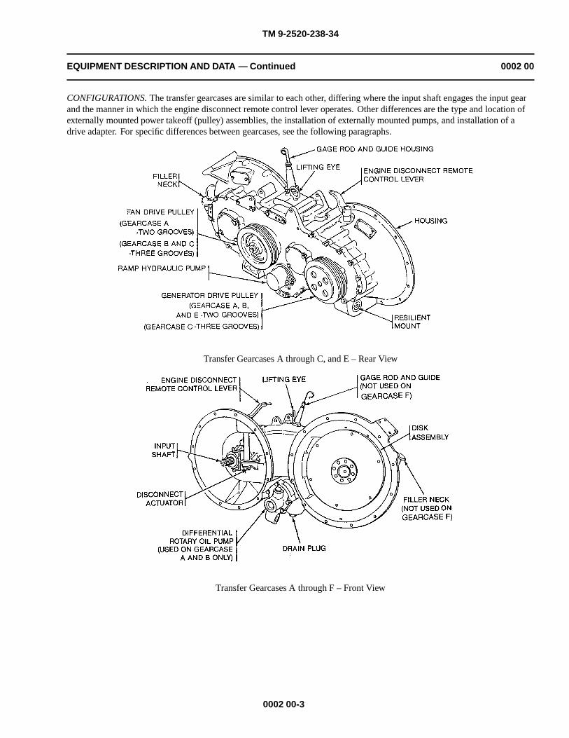
CONFIGURATIONS. The transfer gearcases are similar to each other, differing where the input shaft engages the input gearand the manner in which the engine disconnect remote control lever operates. Other differences are the type and location ofexternally mounted power takeoff (pulley) assemblies, the installation of externally mounted pumps, and installation of adrive adapter. For specific differences between gearcases, see the following paragraphs.
Transfer Gearcases A through C, and E – Rear View
Transfer Gearcases A through F – Front View
0002 00-3

TM 9-2520-238-34
EQUIPMENT DESCRIPTION AND DATA — Continued 0002 00
TRANSFER GEARCASE A. Like gearcases B and C, transfer gearcase A is converted from service spare transfer gearcase E.Gearcase A is used on the M113A1 Family of Vehicles (FOVs). The gearcase has two two-grooved pulleys (one installed onthe input shaft and the other on the hub of the second intermediate gear), a manual engine disconnect remote control lever, anoil filler assembly, an oil level gauge rod and guide, a differential oil pump, and a ramp hydraulic pump. The two pumps aredriven internally by the secondary pump-drive gear. The gearcase is filled with oil through a filler assembly and is drainedthrough a hole at the bottom of the housing. The output gear ratio is 1.268:1, and the maximum input speed is 2800 rpm.When the manually operated engine disconnect remote control lever is actuated, the splined input shaft mounted on the rollerbearings and supported by the input gear, is disengaged from the input gear and the gear train but remains engaged with thepower source (engine) to provide a couple between the engine and drive pulley.
Transfer Gearcases A through C, and E – Rear View
Transfer Gearcases A through F – Front View
0002 00-4

TM 9-2520-238-34
EQUIPMENT DESCRIPTION AND DATA — Continued 0002 00
TRANSFER GEARCASE B AND C. Transfer gearcases B and C are used on the M113A2 FOVs. They are identical togearcase A except the pulleys on the hubs of the second intermediate gears has three grooves and both have a different type ofmanual actuating engine disconnect remote control lever. Gearcase B has a two-groove pulley installed on the input shaft forcarriers with 100 ampere generators. Gearcase C has a three-groove pulley installed on the input shaft for carriers with 200ampere generators.
Transfer Gearcases A through C, and E – Rear View
Transfer Gearcases A through F – Front View
TRANSFER GEARCASE E. Transfer gearcase E is used as the service spare transfer gearcase for gearcases A through C. Thisgearcase has one two-grooved pulley mounted on the input shaft. Mounting hardware is provided for a pulley on the secondintermediate gear and for a manual engine disconnect remote control lever. A dummy shaft replaces the differential oil pump.In place of the ramp hydraulic pump there is an access cover plate.
0002 00-5

TM 9-2520-238-34
EQUIPMENT DESCRIPTION AND DATA — Continued 0002 00
TRANSFER GEARCASE F. Transfer gearcase F is used on the M548A1 carrier. There is no engine disconnect remote controllever. In place of a hydraulic pump there is a spacer and instead of an oil level gauge rod and guide, there is a breather. Unlikegearcases A through C and E, the two-groove pulley is mounted on the hub of the first intermediate gear, not the second.
Transfer Gearcase E Service Spare for Gearcases A through C – Rear View
Transfer Gearcase F – Rear View
STEERING CONTROL DIFFERENTIAL
GENERAL. The steering control differential steers the carrier by means of internal brakes which control gear trains to providerotational velocity differences between output shafts. A thorough understanding of the construction and function of eachassembly as described below is essential for proper maintenance of the differential.
0002 00-6
TM 9-2520-238-34
EQUIPMENT DESCRIPTION AND DATA — Continued 0002 00
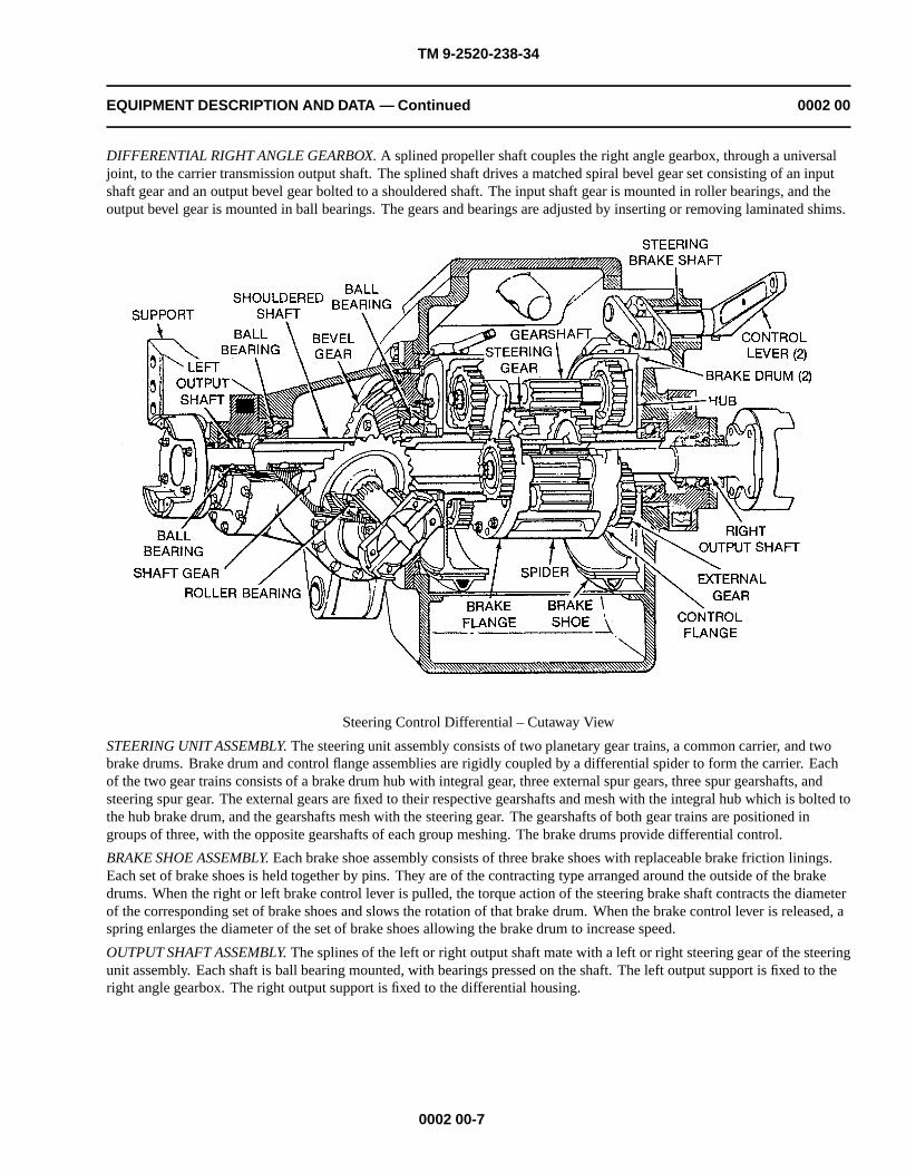
DIFFERENTIAL RIGHT ANGLE GEARBOX. A splined propeller shaft couples the right angle gearbox, through a universaljoint, to the carrier transmission output shaft. The splined shaft drives a matched spiral bevel gear set consisting of an inputshaft gear and an output bevel gear bolted to a shouldered shaft. The input shaft gear is mounted in roller bearings, and theoutput bevel gear is mounted in ball bearings. The gears and bearings are adjusted by inserting or removing laminated shims.
Steering Control Differential – Cutaway View
STEERING UNIT ASSEMBLY. The steering unit assembly consists of two planetary gear trains, a common carrier, and twobrake drums. Brake drum and control flange assemblies are rigidly coupled by a differential spider to form the carrier. Eachof the two gear trains consists of a brake drum hub with integral gear, three external spur gears, three spur gearshafts, andsteering spur gear. The external gears are fixed to their respective gearshafts and mesh with the integral hub which is bolted tothe hub brake drum, and the gearshafts mesh with the steering gear. The gearshafts of both gear trains are positioned ingroups of three, with the opposite gearshafts of each group meshing. The brake drums provide differential control.
BRAKE SHOE ASSEMBLY. Each brake shoe assembly consists of three brake shoes with replaceable brake friction linings.Each set of brake shoes is held together by pins. They are of the contracting type arranged around the outside of the brakedrums. When the right or left brake control lever is pulled, the torque action of the steering brake shaft contracts the diameterof the corresponding set of brake shoes and slows the rotation of that brake drum. When the brake control lever is released, aspring enlarges the diameter of the set of brake shoes allowing the brake drum to increase speed.
OUTPUT SHAFT ASSEMBLY. The splines of the left or right output shaft mate with a left or right steering gear of the steeringunit assembly. Each shaft is ball bearing mounted, with bearings pressed on the shaft. The left output support is fixed to theright angle gearbox. The right output support is fixed to the differential housing.
0002 00-7

TM 9-2520-238-34
EQUIPMENT DESCRIPTION AND DATA — Continued 0002 00
OPERATION
GENERAL. Understanding the movement of parts in relation the movement of the carrier is important for proper maintenanceof the differential. Each steering function, in relation to the operation of parts when the carrier is moving ahead, is describedbelow. When the carrier is in reverse, all parts rotate in the opposite direction.
CARRIER MOVING STRAIGHT AHEAD. The right angle gearbox receives torque into the differential, changes torquedirection 90�, and transmits the torque to the left flange of the steering unit assembly. When the carrier is moving straightahead, the steering unit assembly revolves as a unit about a central axis. The output shafts and brake drums revolve at thesame velocity as the steering unit, with no change in gear rotation, and the external spur gears and gearshafts do not revolveon their own axis.
Steering Control Differential Straight Forward Torque Path
0002 00-8

TM 9-2520-238-34
EQUIPMENT DESCRIPTION AND DATA — Continued 0002 00
CARRIER MOVING TO LEFT WITH LEFT STEERING BRAKE APPLIED. When left brake is applied, the external spur gearsand spur gearshafts continue to rotate at the same velocity. Since the brake impedes or even stops the rotation of the brakedrum hub, the left external gears, in mesh with the hub gear, begin to rotate on their own axes. The gearshafts, fixed to theexternal gears, rotate in a direction which slows the rotation of the left steering spur gear, and the track speed on the left sideof the carrier decreases. At the same time, the right gearshafts, in mesh with companion left gearshafts, rotate in the oppositedirection, which speeds rotation of right steering spur gear, and increases track speed on right side of carrier.
Steering Control Differential Left Steer Torque Path
0002 00-9

TM 9-2520-238-34
EQUIPMENT DESCRIPTION AND DATA — Continued 0002 00
CARRIER MOVING TO RIGHT WITH RIGHT STEERING BRAKE APPLIED. When the right brake is applied, the sameaction takes place in the steering unit assembly as described in the left steering brake applied, except the sequence of motionis from right to left.
Steering Control Differential Right Steer Torque Path
SINGLE DISK PIVOT STEER BRAKE AND HYDRAULIC MASTER BRAKE CYLINDER
GENERAL. Two hydraulic master brake cylinders are connected by linkage to pivot steer levers in the driver’s compartment.Each master brake cylinder is connected by hydraulic hose and tubes to a pivot steer brake that controls rotation of the pivotsteer brake disk mounted on the left and right side of the steering control differential. Actuating the pivot steer lever manuallyto the applied position on the inside of a turn causes the rotation of the brake disk, differential output shaft, and track to lockup on that side. This allows the carrier to make quick turns at low speed (15 mph maximum) and provides steering whenoperating in water.
PIVOT STEER BRAKE ASSEMBLY AND HYDRAULIC MASTER BRAKE CYLINDER. Single disk pivot steer brake andhydraulic brake master cylinder are major components of the pivot steer system installed in carriers listed in Table 1–1,(WP 0001 00). In a pivot steer system, the pivot steer brake assembly has two housings mounted together on a flange on eachside of the differential. The pivot steer brake disk rotates in a gap between the two housings. The master cylinder contains alow pressure piston, high pressure piston, and relief valve. As actuated manually by pivot steer lever, the pistons compress thehydraulic fluid, causing a rise in the fluid line to the pivot steer brake. The relief valve prevents pressure from exceeding apreset level.
PIVOT BRAKE APPLIED. When hydraulic pressure of 20 to 40 psi is applied to the piston in each housing from its masterbrake cylinder, the release units in the housing simultaneously causes the brake linings to press against each side of the brakedisk to stop the disk from turning.
0002 00-10

SPUR GEARSHAFT(14 TEETH ON ASSEMBLY )((13 TEETH ON ASSEMBLY A))
TM 9-2520-238-34
EQUIPMENT DESCRIPTION AND DATA — Continued 0002 00
PIVOT BRAKE RELEASED. Upon release of hydraulic pressure, wave washers in the housings pull the pistons and liningsaway from the brake disk and releasing the disk and output shaft on the differential.
REPAIR FINAL DRIVE ASSEMBLIES
GENERAL. Final drive assemblies transmit power from the steering control differential to the track drive sprockets. The finaldrives consist of reduction gears encased in a forged housing with a cast cover and use a flat gasket to seal the cover to the
FINAL DRIVE ASSEMBLIES A AND B. Final drive A has a spur gearshaft with 13 teeth and a spur gear with 56teeth, resulting in a gear ratio of 4.308:1. Final drive B has a spur gearshaft with 14 teeth and a spur gear with 55 teeth,resulting in a gear ratio of 3.929:1.
Final Drive Assembly A and B
0002 00-11
housing.
SPUR GEARSHAFT(14 TEETH ON ASSEMBLY B)(13 TEETH ON ASSEMBLY A)
SPUR GEAR(55 TEETH ON ASSEMBLY B)(56 TEETH ON ASSEMBLY A)
SPUR GEARSHIFT(14 TEETH ON ASSEMBLY B)(13 TEETH ON ASSEMBLY A)

TM 9-2520-238-34
EQUIPMENT DESCRIPTION AND DATA — Continued 0002 00
LOCATION AND DESCRIPTIONS OF MAJOR COMPONENTS
For differences between components, see Table 1–1, (WP 0001 00).
For configuration data, see Table 1–1, (WP 0001 00).
0002 00-12

TM 9-2520-238-34
REPAIR PARTS, SPECIAL TOOLS, TMDE, AND SUPPORT EQUIPMENT 0003 00
COMMON TOOLS AND EQUIPMENT
For authorized common tools and equipment, see the Modified Table of Organization and Equipment (MTOE) for your unit.
SPECIAL TOOLS, TMDE, AND SUPPORT EQUIPMENT
Special tools you need are listed in Repair Parts and Special Tools List (RPSTL), TM 9-2520-238-34P. Test Measurement andDiagnostic Equipment (TMDE) and special tools are listed in your (WP 0033 00).
FABRICATED TOOLS
These tools enable direct support and general support personnel to fabricate the tools locally. The tools are of particular valueto organizations engaged in repairing a number of identical components. Fabricated tools are not available for issue.Materials and dimensions required for tool fabrication are listed in (WP 0034 00).
REPAIR PARTS
Repair parts are listed and illustrated in the repair parts and special tools list TM 9-2520-238-34P, covering direct and generalsupport maintenance for this equipment. Maintenance and supply personnel can order them.
CHECKING EQUIPMENT
Inspect the equipment for damage incurred during shipment. If the equipment has been damaged, report the damage on formSF 368, Quality Deficiency Report.
0003 00-1/2 blank


TM 9-2520-238-34
CHAPTER 2
TROUBLESHOOTING PROCEDURES
WORK PACKAGE INDEX
Title Sequence No.
INTRODUCTION TO HOW TO USE TROUBLESHOOTING.......................................................................................0004 00
MALFUNCTION/SYMPTOM INDEX WP......................................................................................................................0005 00
COOLING FAN RIGHT ANGLE DRIVE LEAKS OIL...................................................................................................0006 00
COOLING FAN RIGHT ANGLE DRIVE BINDS OR MAKES GRINDING NOISE....................................................0007 00
TRANSFER GEARCASE LEAKS OIL............................................................................................................................0008 00
DIFFERENTIAL MAKES EXCESSIVE NOISE OR VIBRATES WHILE TURNING..................................................0009 00
DIFFERENTIAL MAKES EXCESSIVE NOISE OR VIBRATES WHILE MOVING....................................................0010 00
FINAL DRIVE BINDS OR MAKES GRINDING NOISE...............................................................................................0011 00
FINAL DRIVE LEAKS OIL.............................................................................................................................................0012 00
FINAL DRIVE HAS WATER INSIDE..............................................................................................................................0013 00


TM 9-2520-238-34
INTRODUCTION TO HOW TO USE TROUBLESHOOTING 0004 00
PURPOSE
The purpose of direct and general support maintenance level troubleshooting is to diagnose carrier problems which arereported to direct and general support maintenance. Troubleshooting tasks in this manual are common to all M113 FOVcarriers except where indicated. You should not begin direct and general support maintenance troubleshooting until alloperator and unit troubleshooting procedures have been completed. You will perform four actions in direct and generalsupport maintenance troubleshooting:
(1) Before starting a troubleshooting task, verify that the reported problem is present in the carrier.(2) After verifying the symptom, find the part that is causing the problem.(3) Replace or adjust that part.(4) Check to make sure the problem no longer exists, and that there are no other problems.
DEFINITIONS AND DESCRIPTIONS OF TROUBLESHOOTING PROCEDURES
Troubleshooting tasks always have a beginning and an end. You will use task steps, test procedures, indexes, maintenancetasks, and other technical manuals to troubleshoot. Troubleshooting uses the following terms that are not used in other kindsof tasks:
1. FAULT: The part that is not operating correctly and is causing the problem.
2. SYMPTOM: The problem reported to direct and general support maintenance.
3. VERIFY NO FAULTSFOUND:
After you have completed the corrective action, you must verify that no faults exist.If the fault condition still exists, then the fault is not fixed or there is another fault.If this happens, start at the beginning of the troubleshooting procedure until youfind and correct all faults. Always operate the system and/or carrier to make surethat you have corrected the reported problem. If troubleshooting does not identify afaulty part, the carrier is defective beyond the level of direct and general supportmaintenance.
TROUBLESHOOTING BASICS
Troubleshooting Procedure
A troubleshooting procedure serves as a starting point for your troubleshooting work. You will branch in and out ofprocedures as you work to find a fault. Also, you will correct the fault, and check that the fault has been corrected. The partsof a troubleshooting procedure are given below.
TM 9-2520-238-34
DIFFERENTIAL MAKES EXCESSIVE NOISE OR VIBRATES WHILE MOVING 0010 00
INITIAL SETUP:
Maintenance Level
Direct/General Support
Tools and Special ToolsGeneral mechanic’s tool kit (WP 0034 00, Item 37)
Personnel Required
Track Vehicle Repairer
References
See your-20
Equipment Condition
Differential removed from carrier (See your -20)Disassemble for inspection per repair differential right angle gearbox (WP 0029 00)Repair output shaft assemblies (WP 0025 00)
T TNNO
NOYNY
YES
1. Inspect bevel gear backlash to see if it has been adjusted.2. Has bevel gear backlash been adjusted?
1. Inspect shaft gear bearing to see if it has been adjusted.2. Has shaft gear bearing been adjusted?
1. Adjust bevel gear backlash (WP 0029 00).2. Verify no faults found.
1. Adjust shaft gear bearing (WP 0029 00).2. Verify no faults found.
0004 00-1

TM 9-2520-238-34
INTRODUCTION TO HOW TO USE TROUBLESHOOTING—Continued 0004 00
Legend to Sample Above
1 TITLE This is the name of the procedure.
2 INITIAL SETUP This tells you the tools, materials/parts, personnel, references, and equipmentconditions needed to do the procedure.
3 TASK STEPS These boxes give you step-by-step instructions.
4 QUESTIONS This is the last step in YES blocks. The answer to this question will direct you tothe next block.
5 BLOCK ID CODE These codes identify YES/NO blocks for ease of referencing.
Locating the Correct Troubleshooting Procedure
(1) Component arrives at shop.(2) Read DA form 2404.(3) Verify that the problem on DA form 2404 exists.(4) Look up the carrier symptom in Troubleshooting Task Index, (WP 0005 00), in this chapter, and go to that task.
Doing the Troubleshooting Procedure
(1) Make sure you have all items in INITIAL SETUP.(2) Perform required action(s) in Equipment Conditions.(3) Complete the first block of task steps.(4) Refer to system schematic or diagram for system components, detail, and clarification.(5) Answer the question at the bottom of the first block.(6) Follow YES or NO arrows to the next block.(7) Move from block to block. Answer questions and follow instructions. You may be directed to:
do further checks and tests on parts; orgo to another tasks.
NOTE
After completing the actions called for on another page, return to the point in thetroubleshooting procedure where you left off.
(8) Locate the fault in the carrier or part and perform the corrective action.(9) Check to make sure fault is corrected, and no new faults are found.(10) Button up by reinstalling items in Equipment Conditions after finishing the troubleshooting task.
TROUBLESHOOTING SAMPLE
The following sample takes you through a typical troubleshooting procedure.
0004 00-2

TM 9-2520-238-34
INTRODUCTION TO HOW TO USE TROUBLESHOOTING—Continued 0004 00
Finding the Right Troubleshooting Procedure
A component arrives at the shop. The DA form 2404 shows that the differential makes excessive noise or vibrates whilemoving. Therefore, you look up differential makes excessive noise or vibrates while moving will be listed in Malfunction/Symptom Index, (WP 0005 00), in this chapter.
TM 9-2520-238-34
MALFUNCTION/SYMPTOM INDEX WP 0005 00
COOLING SYSTEM
TRANSFER GEARCASE
FINAL DRIVE ASSEMBLIES
REAR AXLE
COOLING FAN RIGHT ANGLE DRIVE LEAKS OIL..........................................................................WP 0006 00 COOLING FAN RIGHT ANGLE DRIVE BINDS OR MAKES GRINDING NOISE...............................................................................................................................................WP 0007 00
TRANSFER GEARCASE LEAKS OIL...............................................................................................WP 0008 00
FINAL DRIVE BINDS OF MAKES GRINDING NOISE......................................................................WP 0011 00 FINAL DRIVE LEAKS OIL..................................................................................................................WP 0012 00 FINAL DRIVE HAS WATER INSIDE..................................................................................................WP 0013 00
DIFFERENTIAL MAKES EXCESSIVE NOISE OR VIBRATES WHILETURNING...........................................................................................................................................WP 0009 00DIFFERENTIAL MAKES EXCESSIVE NOISE OR VIBRATES WHILEMOVING............................................................................................................................................WP 0010 00
This is the procedure you want.
TM 9-2520-238-34
DIFFERENTIAL MAKES EXCESSIVE NOISE OR VIBRATES WHILE MOVING 0010 00
INITIAL SETUP:
Maintenance Level
Direct/General Support
Tools and Special ToolsGeneral mechanic’s tool kit (WP 0034 00, Item 37)
Personnel Required
Track Vehicle Repairer
References
See your-20
Equipment Condition
Differential removed from carrier (See your -20) Disassemble for inspection per repair differential right angle gearbox (WP 0029 00)Repair output shaft assemblies (WP 0025 00)
T TNNO
NO
NO
NO
YN
2YN
3YN
4YNNO
Y
2Y
3Y
4Y
YES
YES
YES
YES
YES
1. Inspect bevel gear backlash to see if it has been adjusted. 2. Has bevel gear backlash been adjusted?
1. Inspect shaft gear bearing to see if it has been adjusted. 2. Has shaft gear bearing been adjusted?
1. Inspect shaft gear bearings for damage. 2. Are shaft gear bearings undamaged?
1. Inspect bevel gear shaft bearings (WP 0029 00). 2. Are bevel gear teeth undamaged?
1. Inspect output shaft bearings. 2. Are output shaft bearings serviceable?
1. Adjust bevel gear backlash (WP 0029 00). 2. Verify no faults found.
1. Adjust shaft gear bearing (WP 0029 00). 2. Verify no faults found.
1. Replace damaged bevel gear shaft bearing (WP 0029 00). 2. Verify no faults found.
1. Replace damaged shaft gear bearings (WP 0029 00). 2. Verify no faults found.
1. Replace output shaft bearings (WP 0025 00). 2. Verify no faults found.
0010 00-1
0004 00-3
TM 9-2520-238-34
INTRODUCTION TO HOW TO USE TROUBLESHOOTING—Continued 0004 00
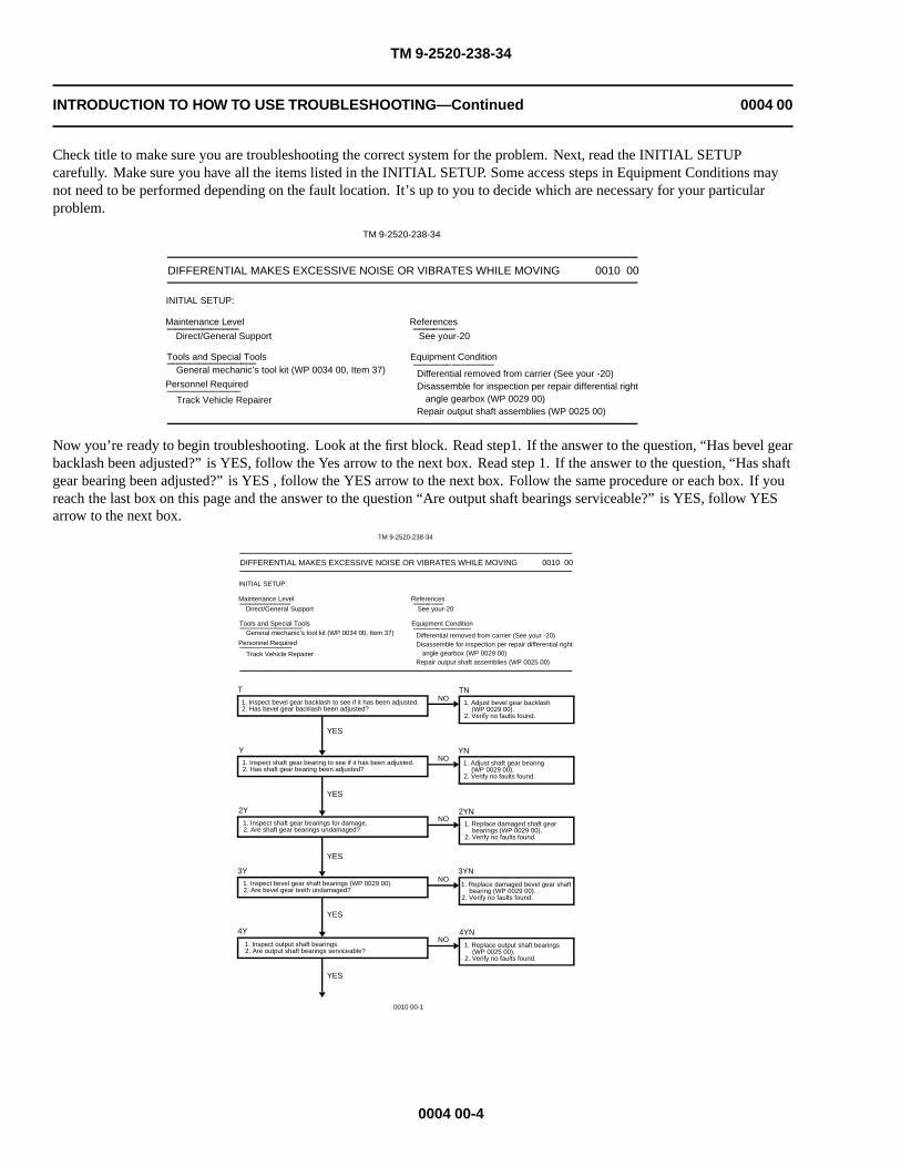
Check title to make sure you are troubleshooting the correct system for the problem. Next, read the INITIAL SETUPcarefully. Make sure you have all the items listed in the INITIAL SETUP. Some access steps in Equipment Conditions maynot need to be performed depending on the fault location. It’s up to you to decide which are necessary for your particularproblem.
TM 9-2520-238-34
DIFFERENTIAL MAKES EXCESSIVE NOISE OR VIBRATES WHILE MOVING 0010 00
INITIAL SETUP:
Maintenance Level
Direct/General Support
Tools and Special ToolsGeneral mechanic’s tool kit (WP 0034 00, Item 37)
Personnel Required
Track Vehicle Repairer
References
See your-20
Equipment Condition
Differential removed from carrier (See your -20) Disassemble for inspection per repair differential right angle gearbox (WP 0029 00)Repair output shaft assemblies (WP 0025 00)
Now you’re ready to begin troubleshooting. Look at the first block. Read step1. If the answer to the question, “Has bevel gearbacklash been adjusted?” is YES, follow the Yes arrow to the next box. Read step 1. If the answer to the question, “Has shaftgear bearing been adjusted?” is YES , follow the YES arrow to the next box. Follow the same procedure or each box. If youreach the last box on this page and the answer to the question “Are output shaft bearings serviceable?” is YES, follow YESarrow to the next box.
TM 9-2520-238-34
DIFFERENTIAL MAKES EXCESSIVE NOISE OR VIBRATES WHILE MOVING 0010 00
INITIAL SETUP:
Maintenance Level
Direct/General Support
Tools and Special ToolsGeneral mechanic’s tool kit (WP 0034 00, Item 37)
Personnel Required
Track Vehicle Repairer
References
See your-20
Equipment Condition
Differential removed from carrier (See your -20) Disassemble for inspection per repair differential right angle gearbox (WP 0029 00)Repair output shaft assemblies (WP 0025 00)
T TNNO
NO
NO
NO
YN
2YN
3YN
4YNNO
Y
2Y
3Y
4Y
YES
YES
YES
YES
YES
1. Inspect bevel gear backlash to see if it has been adjusted. 2. Has bevel gear backlash been adjusted?
1. Inspect shaft gear bearing to see if it has been adjusted. 2. Has shaft gear bearing been adjusted?
1. Inspect shaft gear bearings for damage. 2. Are shaft gear bearings undamaged?
1. Inspect bevel gear shaft bearings (WP 0029 00). 2. Are bevel gear teeth undamaged?
1. Inspect output shaft bearings. 2. Are output shaft bearings serviceable?
1. Adjust bevel gear backlash (WP 0029 00). 2. Verify no faults found.
1. Adjust shaft gear bearing (WP 0029 00). 2. Verify no faults found.
1. Replace damaged bevel gear shaft bearing (WP 0029 00). 2. Verify no faults found.
1. Replace damaged shaft gear bearings (WP 0029 00). 2. Verify no faults found.
1. Replace output shaft bearings (WP 0025 00). 2. Verify no faults found.
0010 00-1
0004 00-4

TM 9-2520-238-34
INTRODUCTION TO HOW TO USE TROUBLESHOOTING—Continued 0004 00
This is how the box appears once you located it. Do steps 1 and 2. In this sample, if the answer to step 2 is NO, follow theNO arrow to the reference indicated.
TM 9-2520-238-34
DIFFERENTIAL MAKES EXCESSIVE NOISE OR VIBRATES WHILE MOVING-Continued 0010 00
5Y 5YNNO
YES
1. Inspect bevel gear set. 2. Is bevel gear set undamaged?
1. Replace damaged bevel gear set (WP 0029 00). 2. Verify no faults found.
The NO arrow takes you to this box. You have decided the drum brake is not serviceable. This box gives you the step tocorrect the fault. Do step 1. It tells you to go to another task in the manual. Go to the page shown and perform the task.Return to this box when you have completed the task.
5YNNO
1. Replace damaged bevel gear set (WP 0029 00). 2. Verify no faults found.
Step 2 in this box is “Verify no faults found.” You must check to make sure you have correctly fixed the fault.
After no faults found has been verified, return carrier to operation. This is the end of the troubleshooting sample.
0004 00-5/6 blank


TM 9-2520-238-34
MALFUNCTION/SYMPTOM INDEX WP 0005 00
COOLING SYSTEM
COOLING FAN RIGHT ANGLE DRIVE LEAKS OIL.......................................................................................WP 0006 00COOLING FAN RIGHT ANGLE DRIVE BINDS OR MAKES GRINDING
NOISE..................................................................................................................................................................WP 0007 00
TRANSFER GEARCASE
TRANSFER GEARCASE LEAKS OIL................................................................................................................WP 0008 00
REAR AXLE
DIFFERENTIAL MAKES EXCESSIVE NOISE OR VIBRATES WHILETURNING............................................................................................................................................................WP 0009 00
DIFFERENTIAL MAKES EXCESSIVE NOISE OR VIBRATES WHILEMOVING..............................................................................................................................................................WP 0010 00
0005 00-1/2 blank
FINAL DRIVE ASSEMBLIES
FINAL DRIVE BINDS OF MAKES GRINDING NOISE....................................................................................WP 0011 00FINAL DRIVE LEAKS OIL..................................................................................................................................WP0012 00FINAL DRIVE HAS WATER INSIDE..................................................................................................................WP 0013 00


TM 9-2520-238-34
COOLING FAN RIGHT ANGLE DRIVE LEAKS OIL 0006 00
INITIAL SETUP:
Maintenance Level
Direct Support
Tools and Special Tools
General mechanic’s tool kit (WP 0033 00, Item 37)
Personnel Required
Track Vehicle Repairer
References
See your -34
Equipment Condition
Right angle drive removed from fan assembly (See your-34)
Disassemble for inspection per repair cooling fan rightangle drives A, B (WP 0015 00) or C (WP 0016 00)
T1. Inspect oil seals for damage.2. Are oil seals undamaged?
YES
NOTN1. Replace damaged oil seals
(WP 0015 00, WP 0016 00).2. Verify no faults found.
Y1. Inspect preformed packings for wear or damage.2. Are preformed packings serviceable?
YES
NOYN1. Replace worn or damaged preformed
packing (WP 0015 00, WP 0016 00).2. Verify no faults found.
2Y1. Replace right angle drive housing.2. Notify your supervisor.
0006 00-1/2 blank


TM 9-2520-238-34
COOLING FAN RIGHT ANGLE DRIVE BINDS OR MAKES GRINDING NOISE 0007 00
INITIAL SETUP:
Maintenance Level
Direct Support
Tools and Special Tools
General mechanic’s tool kit (WP 0033 00, Item 37)
Personnel Required
Track Vehicle Repairer
References
See your -34
Equipment Condition
Right angle drive removed from fan assembly (See your-34)
Disassemble for inspection per repair cooling fan rightangle drives A, B (WP 0015 00) or C (WP 0016 00)
T1. Inspect bearings for damage.2. Are bearings undamaged?
YES
NOTN1. Replace damaged bearings
(WP 0015 00, WP 0016 00).2. Verify no faults found.
Y1. Inspect spindle assembly for damage.2. Is spindle assembly undamaged?
YES
NOYN1. Replace damaged spindle assembly
(WP 0015 00, WP 0016 00).2. Verify no faults found.
2Y1. Suspect broken or ground up spindle pin.2. Notify your supervisor.
0007 00-1/2 blank


TM 9-2520-238-34
TRANSFER GEARCASE LEAKS OIL 0008 00
INITIAL SETUP:
Maintenance Level
Direct/General Support
Tools and Special Tools
General mechanic’s tool kit (WP 0033 00, Item 37)
Personnel Required
Track Vehicle Repairer
References
See your -20
Equipment Condition
Transfer gearcase removed from carrier (See your -20 &-34)
Disassemble for inspection per repair transfer gearcaseA, B, C (WP 0017 00), E (WP 0018 00) or F(WP 0019 00)
T1. Inspect oil seal for improper installation, wear or damage.2. Are oil seals serviceable?
YES
NOTN1. Replace worn or damaged oil seal
(WP 0017 00WP 0019 00).2. Verify no faults found.
Y1. Inspect shafts for nicks or scratches near oil seal.2. Are shafts free of nicks and scratches?
YES
NOYN1. Polish out marks or replace damaged
shaft (WP 0017 00, WP 0019 00).2. Verify no faults found.
2Y1. Inspect input shaft and output shaft dirt deflectors for damage.2. Are dirt deflectors serviceable?
YES
NO2YN1. Replace missing or damaged dirt
deflectors (WP 0017 00,WP 0019 00).
2. Verify no faults found.
3Y1. Inspect gearcase housing and cover for cracks.2. Are housing and cover free of cracks?
YES
NO3YN1. Replace damaged cover or housing
(WP 0017 00, WP 0019 00).2. Verify no faults found.
0008 00-1

TM 9-2520-238-34
TRANSFER GEARCASE LEAKS OIL—Continued 0008 00
4Y1. Inspect shaft or oil pump for leaking oil.2. Is oil leaking from a shaft or oil pump?
YES
NO4YN1. Tighten housing and cover screws
(WP 0017 00, WP 0019 00).2. Verify no faults found.
5Y1. Inspect shaft for leaking oil.2. Is oil leaking from a shaft?
YES
NO5YN1. Replace preformed packing
(WP 0017 00, WP 0019 00) or gasket(WP 0017 00, WP 0019 00) on oilpump bracket as required.
2. Verify no faults found.
6Y1. Replace preformed packing and seal (WP 0017 00, WP 0019 00).2. Verify no faults found.
0008 00-2

TM 9-2520-238-34
DIFFERENTIAL MAKES EXCESSIVE NOISE OR VIBRATES WHILETURNING
0009 00
INITIAL SETUP:
Maintenance Level
Direct/General Support
Tools and Special Tools
General mechanic’s tool kit (WP 0033 00, Item 37)
Personnel Required
Track Vehicle Repairer
ReferencesSee your -20
Equipment ConditionDifferential removed from carrier (See your -20)Brake shoe assembly removed (WP 0021 00)Disassemble for inspection per repair brake shoe
assemblies (WP 0022 00)Repair differential steering control assembly
(WP 0026 00)Repair differential right angle gearbox (WP 0028 00)
T1. Inspect differential brakes for damage.2. Are brakes serviceable?
YES
NOTN1. Replace damaged brake lining, drum
or hub as required (WP 0022 00,WP 0026 00).
2. Verify no faults found.
Y1. Inspect differential gearshaft for damage.2. Is gearshaft true and free of nicks and scratches?
YES
NOYN1. Replace damaged differential
gearshaft (WP 0026 00).2. Verify no faults found.
2Y1. Inspect differential spur gears for misalignment and damage.2. Are spur gears aligned and undamaged?
YES
NO2YN1. Replace damaged gear
(WP 0026 00).2. Adjust misaligned spur gear
(WP 0026 00).3. Verify no faults found.
3Y1. Inspect differential bevel gear set for misalignment or damaged
teeth.2. Are bevel gear teeth wearing properly?
YES
NO3YN1. Replace misaligned or damaged
differential bevel gear (WP 0028 00).2. Verify no faults found.
0009 00-1

TM 9-2520-238-34
DIFFERENTIAL MAKES EXCESSIVE NOISE OR VIBRATES WHILE TURNING—Continued 0009 00
4Y1. Inspect flange bearings for wear and damage.2. Are flange bearing serviceable?
YES
NO4YN1. Replace worn or damaged flange
bearings (WP 0026 00).2. Verify no faults found.
5Y1. Suspect faulty right angle drive.2. Notify your supervisor.
0009 00-2

TM 9-2520-238-34
DIFFERENTIAL MAKES EXCESSIVE NOISE OR VIBRATES WHILE MOVING 0010 00
INITIAL SETUP:
Maintenance Level
Direct/General Support
Tools and Special Tools
General mechanic’s tool kit (WP 0033 00, Item 37)
Personnel Required
Track Vehicle Repairer
References
See your -20
Equipment Condition
Differential removed from carrier (See your -20)Disassemble for inspection per repair differential right
angle gearbox (WP 0028 00)Repair output shaft assemblies (WP 0024 00)
T1. Inspect bevel gear backlash to see if it has been adjusted.2. Has bevel gear backlash been adjusted?
YES
NOTN1. Adjust bevel gear backlash
(WP 0028 00).2. Verify no faults found.
Y1. Inspect shaft gear bearing to see if it has been adjusted.2. Has shaft gear bearing been adjusted?
YES
NOYN1. Adjust shaft gear bearing
(WP 0028 00).2. Verify no faults found.
2Y1. Inspect shaft gear bearings for damage.2. Are shaft gear bearings undamaged?
YES
NO2YN1. Replace damaged shaft gear bearings
(WP 0028 00).2. Verify no faults found.
3Y1. Inspect bevel gear shaft bearings (WP 0029 00).2. Are bevel gear teeth undamaged?
YES
NO3YN1. Replace damaged bevel gear shaft
bearing (WP 0028 00).2. Verify no faults found.
4Y1. Inspect output shaft bearings.2. Are output shaft bearings serviceable?
YES
NO4YN1. Replace output shaft bearings
(WP 0024 00).2. Verify no faults found.
0010 00-1

TM 9-2520-238-34
DIFFERENTIAL MAKES EXCESSIVE NOISE OR VIBRATES WHILE MOVING—Continued 0010 00
5Y1. Inspect bevel gear set.2. Is bevel gear set undamaged?
YES
NO5YN1. Replace damaged bevel gear set
(WP 0028 00).2. Verify no faults found.
6Y1. Inspect brake drum.2. Is brake drum serviceable?
YES
NO6YN1. Replace brake drum (WP 0026 00).2. Verify no faults found.
7Y1. Inspect brake linings.2. Are brake linings serviceable?
YES
NO7YN1. Replace brake linings (WP 0022 00).2. Verify no faults found.
8Y1. Verify no faults found.2. Notify your supervisor.
0010 00-2

TM 9-2520-238-34
FINAL DRIVE BINDS OR MAKES GRINDING NOISE 0011 00
INITIAL SETUP:
Maintenance Level
Direct/General Support
Tools and Special Tools
General mechanic’s tool kit (WP 0033 00, Item 37)
Personnel Required
Track Vehicle Repairer
References
See your -20
Equipment Condition
Final drive removed from carrier (See your -20)Disassemble for inspection per repair final drive
assemblies A, B (WP 0020 00)
T1. Inspect final drive if it can be rotated by hand.2. Can final drive be rotated by hand?
YES
NOTN1. Replace output shaft bearing
(WP 0020 00).2. Verify no faults found.
Y1. Inspect gears for damage.2. Are gears undamaged?
YES
NOYN1. Replace damaged gears
(WP 0020 00).2. Verify no faults found.
2Y1. Suspect loose parts inside unit.2. Notify your supervisor.
0011 00-1/2 blank


TM 9-2520-238-34
FINAL DRIVE LEAKS OIL 0012 00
INITIAL SETUP:
Maintenance Level
Direct/General Support
Tools and Special Tools
General mechanic’s tool kit (WP 0033 00, Item 37)
Personnel Required
Track Vehicle Repairer
References
See your -20
Equipment Condition
Final drive removed from carrier (See your -20)Disassemble for inspection per repair final drive
assemblies A, B (WP 0020 00)
T1. Inspect preformed packing for wear, damage or improper seating.2. Are oil seals undamaged?
YES
NOTN1. Replace worn, damaged or
improperly seated preformed packing(WP 0020 00).
2. Verify no faults found.
Y1. Inspect output shaft seal for damage.2. Is output shaft seal undamaged?
YES
NOYN1. Replace damaged output shaft seal
(WP 0020 00).2. Verify no faults found.
2Y1. Inspect output shaft for nicks or scratches near seal.2. Is output shaft free of nicks or scratches?
YES
NO2YN1. Polish out marks or replace shaft
(WP 0020 0 00).2. Verify no faults found.
3Y1. Inspect output shaft bearing for damage.2. Is output shaft bearing undamaged?
YES
NO3YN1. Replace damaged output shaft
bearing(WP 0020 00). .2. Verify no faults found.
4Y1. Tighten housing and cover screws.2. Notify your supervisor.
0012 00-1/2 blank


TM 9-2520-238-34
FINAL DRIVE HAS WATER INSIDE 0013 00
INITIAL SETUP:
Maintenance Level
Direct/General Support
Tools and Special Tools
General mechanic’s tool kit (WP 0033 00, Item 37)
Personnel Required
Track Vehicle Repairer
References
See your -20
Equipment Condition
Final drive removed from carrier (See your -20)Disassemble for inspection per repair final drive
assemblies A, B (WP 0020 00)
T1. Inspect output shaft oil seal for damage.2. Are oil seals undamaged?
YES
NOTN1. Replace damaged output shaft oil
seal (WP 0020 00).2. Verify no faults found.
Y1. Inspect cover and housing for damage.2. Are cover and housing undamaged?
YES
NOYN1. Replace damaged cover and/or
housing if required (WP 0020 00).
2. Verify no faults found.
2Y1. Inspect oil fill tube and nut for proper fit.2. Is nut on oil tube undamaged?
YES
NO2YN1. Tighten oil fill tube nut (See your
-20).2. Verify no faults found.
3Y1. Tighten cover and housing screws.2. Verify no faults found.
0013 00-1/2 blank

TM 9-2520-238-34
CHAPTER 3
DIRECT SUPPORT MAINTENANCE INSTRUCTIONSFOR PMCS INCLUDING LUBRICATION PROCEDURES
WORK PACKAGE INDEX
Title Sequence No.
PREVENTIVE MAINTENANCE CHECKS AND SERVICES (PMCS), INCLUDINGLUBRICATION INSTRUCTIONS..........................................................................................................................0014 00

TM 9-2520-238-34
PREVENTIVE MAINTENANCE CHECKS AND SERVICES (PMCS),INCLUDING LUBRICATION INSTRUCTIONS
0014 00
THIS WORK PACKAGE COVERS:
INITIAL SETUP:
Maintenance Level
Direct Support
GENERAL MAINTENANCE INSTRUCTIONS
SCOPE
This section contains safety warnings, guidelines, and general maintenance instructions. They should be followed when doingmaintenance procedures authorized for direct and general support maintenance levels.
PREPARATION FOR MAINTENANCE
1. PERSONNEL SAFETY. Practice all shop safety procedures and read all warnings in this manual.
2. PROPER EQUIPMENT. Get tools and equipment before starting a maintenance task. See TM 9-2520-238-34P, andthe maintenance tasks for tools, equipment, parts, and materials.
3. WHAT TO DISCARD. Parts to discard, such as lockwashers, locknuts, and gaskets are listed in the maintenance tasks.If the step does not say to discard a part, the part should be saved. It may be used later, or repaired.
4. HANDLING TECHNIQUES.
a. Avoid damage to parts during disassembly, cleaning, inspection, repair, and reassembly procedures. Nicks,scratches, and dents caused by careless handling could result in equipment failure.
b. Dirt can damage parts and cause malfunctions. Make sure all air and fluid openings, lines, and hoses are capped orplugged during maintenance procedures.
5. IDENTIFICATION.
a. During disassembly, tag parts to ensure proper assembly.
b. During disassembly, tag leads on electrical parts to ensure proper assembly. Tag each lead, as it is removed, withnumbers from wiring diagrams and terminals.
0014 00-1

TM 9-2520-238-34
PREVENTIVE MAINTENANCE CHECKS AND SERVICES (PMCS), INCLUDINGLUBRICATION INSTRUCTIONS — Continued
0014 00
6. TORQUING. Where needed, torque values are listed in the maintenance task. When torquing, use one of the starpattern sequences below unless otherwise stated in the maintenance task.
6–HOLE PATTERN
8–HOLE PATTERN
10–HOLE PATTERN
0014 00-2

TM 9-2520-238-34
PREVENTIVE MAINTENANCE CHECKS AND SERVICES (PMCS), INCLUDINGLUBRICATION INSTRUCTIONS — Continued
0014 00
12–HOLE PATTERN
1
2
34
5
6 7
8 9
10 11
12
13
14
15
16
17
17–HOLE PATTERN
7. TORQUE WRENCH ADAPTERS AND CONVERSION FORMULA.
a. Torque wrench adapters (extensions) are used to tighten screws and nuts to specific values that cannot be reachedwith a regular socket on the end of a torque wrench. This makes the dial or scale reading less than the actual torqueapplied to the screw or nut. When using an adapter, determine the dial or scale reading as follows:
1) Check your manual for specific torque value to which the screw or nut should be tightened.
2) Measure the length of your torque wrench, from the center of the handle (point A) to the center of the socket(point B). Record this measurement.
3) Multiply the above measurement by the desired torque. Record this sum.
4) Measure length of adapter from socket end (point C) to screw or nut end (point D). Record this measurement.
5) Add length of adapter (Step 7a4) to the length of the torque wrench (Step 7a2). Record this sum.
6) Divide the sum found in Step 7a3 by the sum found in Step 7a5.
7) The sum found in Step 7a6 is your torque wrench setting. Set your dial.
0014 00-3

TM 9-2520-238-34
PREVENTIVE MAINTENANCE CHECKS AND SERVICES (PMCS), INCLUDINGLUBRICATION INSTRUCTIONS — Continued
0014 00
NOTE
Setting the torque wrench dial at the reading found in Step 7a7 will deliver the required torqueat the end of your adapter.
Example: (Metric equivalents omitted for clarity).1) 40 lb-ft required.2) 12 inches.3) 12 x 40 = 480.4) 4 inches.5) 12 + 4 = 16 inches.6) 480/16 = 30 lb-ft.7) Torque wrench dial setting = 30.
CLEANING
8. GENERAL. Cleaning is very important. All parts must be cleaned well and kept clean during maintenance. Dirt orforeign matter can cause malfunctions and equipment failure. General cleaning procedures are detailed in the followingsteps. Special cleaning procedures are covered in the task relating to the specific part. Clean after repair and beforeassembly.
9. CLEAN EVERY PART. Clean every part well after disassembly and before assembly or installation. Clean parts suchas housings, covers, and dipsticks before disassembly. Avoid getting dirt and foreign matter in a system.
10. HANDLE WITH CARE. Use care when handling parts during cleaning and maintenance. Nicks, scratches, dents, andburrs can prevent proper assembly or cause malfunctions after assembly.
11. AVOID ABRASIVES. Except where specially called for in a task, don’t use abrasives, files, wire brushes, or sharptools. On some surfaces, finish is important to the operation of close fitting parts.
12. REMOVAL AGENTS. Remove gum or old grease deposits by soaking parts in cleaning compound WP 0035 00, Item4. Scrub with a brush. Use crocus cloth to remove minor surface defects.
0014 00-4

TM 9-2520-238-34
PREVENTIVE MAINTENANCE CHECKS AND SERVICES (PMCS), INCLUDINGLUBRICATION INSTRUCTIONS — Continued
0014 00
WARNING
Air pressure in excess of 30 psi (207 kPa) can injure personnel. Do not direct pressurized air atyourself or others. Always wear goggles.
CAUTION
Lye or caustic substances will damage metal surfaces. Do not use lye or caustic mixtures toclean metal surfaces.
13. STEAM CLEANING. If steam cleaning is used, dry clean parts at once with compressed air. Apply a thin film of cleanoil to surfaces that are not painted to prevent rusting. Never use lye of caustic mixtures that will corrode or etch metalsurfaces.
14. LUBRICATION OF NEW BEARINGS. See TM 9-214 for cleaning and lubrication procedures. Bearings that havebeen in service should also be lubricated.
15. CLEANING INSTRUCTIONS. Care is needed in all cleaning procedures. Dirt can damage parts and causemalfunctions. When you perform any cleaning procedure, do the following:
a. Inspect and cap all air and fluid openings, lines, and hoses.
b. Clean all parts before inspection, after repair, and before assembly. Use cleaning compound WP 0035 00, Item 4 orapproved cleaner. Dry parts with wiping rag WP 0035 00, Item 17.
c. Keep hands free of grease. Grease collects dirt.
d. After cleaning, cover or wrap parts to protect from dirt.
WARNING
Air pressure in excess of 30 psi (207 kPa) can injure personnel. Do not direct pressurized air atyourself or others. Always wear goggles.
16. CASTINGS.
a. Clean inner and outer surfaces of casting with cleaning compound WP 0035 00, Item 4. Dry casting withcompressed air.
b. Remove sludge and gum deposits with a brush.
c. Blow out all tapped holes and armor mounting inserts with compressed air.
0014 00-5

TM 9-2520-238-34
PREVENTIVE MAINTENANCE CHECKS AND SERVICES (PMCS), INCLUDINGLUBRICATION INSTRUCTIONS — Continued
0014 00
WARNING
Air pressure in excess of 30 psi (207 kPa) can injure personnel. Do not direct pressurized air atyourself or others. Always wear goggles.
17. BALL BEARINGS. Bearings require special cleaning techniques. See TM 9-214 for cleaning and maintenanceprocedures for ball bearings.
WARNING
Air pressure in excess of 30 psi (207 kPa) can injure personnel. Do not direct pressurized air atyourself or others. Always wear goggles.
18. OIL PASSAGES.
a. Make sure all oil passages are not clogged.
b. Clean oil passages and break up any sludge or gum deposits.
c. Flush oil passages with cleaning compound WP 0035 00, Item 4. Dry parts with compressed air.
CAUTION
Cleaning solvent causes leather, rubber, and synthetic materials to become brittle. Do not usecleaning solvent to clean seals, cables, and flexible hoses.
19. OIL SEALS AND FLEXIBLE HOSES. Clean seals, cables, and flexible hoses with detergent and water. Dry partswith wiping rag WP 0035 00, Item 17.
WARNING
Air pressure in excess of 30 psi (207 kPa) can injure personnel. Do not direct pressurized air atyourself or others. Always wear goggles.
20. INSERTS. Blow out insert holes with compressed air.
21. GASKETS. If gasket is being removed, scrape old gasket material and sealant off mating surface. Clean mating surfacewith cleaning compound WP 0035 00, Item 4. Dry with wiping rag WP 0035 00, Item 17.
0014 00-6
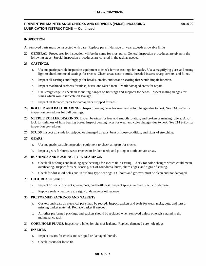
TM 9-2520-238-34
PREVENTIVE MAINTENANCE CHECKS AND SERVICES (PMCS), INCLUDINGLUBRICATION INSTRUCTIONS — Continued
0014 00
INSPECTION
All removed parts must be inspected with care. Replace parts if damage or wear exceeds allowable limits.
22. GENERAL. Procedures for inspection will be the same for most parts. General inspection procedures are given in thefollowing steps. Special inspection procedures are covered in the task as needed.
23. CASTINGS.
a. Use magnetic particle inspection equipment to check ferrous castings for cracks. Use a magnifying glass and stronglight to check nonmetal castings for cracks. Check areas next to studs, threaded inserts, sharp corners, and fillets.
b. Inspect all castings and forgings for breaks, cracks, and wear or scoring that would impair function.
c. Inspect machined surfaces for nicks, burrs, and raised metal. Mark damaged areas for repair.
d. Use straightedge to check all mounting flanges on housings and supports for bends. Inspect mating flanges forstains which would indicate oil leakage.
e. Inspect all threaded parts for damaged or stripped threads.
24. ROLLER AND BALL BEARINGS. Inspect bearing races for wear and color changes due to heat. See TM 9-214 forinspection procedures for ball bearings.
25. NEEDLE ROLLER BEARINGS. Inspect bearings for free and smooth rotation, and broken or missing rollers. Alsolook for tightness of fit in bearing bores. Inspect bearing races for wear and color changes due to heat. See TM 9-214 forinspection procedures.
26. STUDS. Inspect all studs for stripped or damaged threads, bent or loose condition, and signs of stretching.
27. GEARS.
a. Use magnetic particle inspection equipment to check all gears for cracks.
b. Inspect gears for burrs, wear, cracked or broken teeth, and pitting at tooth contact areas.
28. BUSHINGS AND BUSHING-TYPE BEARINGS.
a. Check all bushings and bushing-type bearings for secure fit in casting. Check for color changes which could meanoverheating. Inspect for size, scoring, out-of-roundness, burrs, sharp edges, and signs of seizing.
b. Check for dirt in oil holes and in bushing type bearings. Oil holes and grooves must be clean and not damaged.
29. OIL/GREASE SEALS.
a. Inspect lip seals for cracks, wear, cuts, and brittleness. Inspect springs and seal shells for damage.
b. Replace seals when there are signs of damage or oil leakage.
30. PREFORMED PACKINGS AND GASKETS
a. Gaskets and seals on electrical parts may be reused. Inspect gaskets and seals for wear, nicks, cuts, and torn ormissing gasket material. Replace gasket if needed.
b. All other preformed packings and gaskets should be replaced when removed unless otherwise stated in themaintenance task.
31. CORE HOLE PLUGS. Inspect core holes for signs of leakage. Replace damaged core hole plugs.
32. INSERTS.
a. Inspect inserts for cracks and stripped or damaged threads.
b. Check inserts for loose fit.
0014 00-7

TM 9-2520-238-34
PREVENTIVE MAINTENANCE CHECKS AND SERVICES (PMCS), INCLUDINGLUBRICATION INSTRUCTIONS — Continued
0014 00
33. SPLINED PARTS. Inspect splined parts for burrs, wear, and twisted, cracked or broken splines.
34. THREADED PARTS. Inspect all threaded parts for burrs, and stripped or damaged threads.
35. RETAINING RINGS. Inspect retaining rings for nicks, burrs, defects, loss of tension, or wear.
36. SPRINGS. Inspect springs for wear, defects, breaks, and loss of tension or compression. Inspect springs using a springtester.
37. SHAFTS AND SPINDLES. Inspect shafts and spindles for excessive wear, binding, scores, cracks, burrs, andobstructed oil passages.
REPAIR
38. GENERAL. General repair procedures are given in the following steps. Special repairs are covered in the task. Afterrepair, clean all parts well.
39. CASTINGS.
a. Replace all cracked or broken castings.
b. Repair minor damage to machined surfaces of castings with crocus cloth. Replace any part with defects that cannotbe corrected or which will impair function.
c. Repair minor surface bends by working bent surface of casting across sheet of crocus cloth on surface plate.Replace bent castings which would impair assembly or function.
d. Repair damaged pipe or screw threads with correct tap or die.
40. BALL BEARINGS. See TM 9-214 for inspection and maintenance of ball bearings.
41. NEEDLE ROLLER BEARINGS. See TM 9-214 for inspection and maintenance of needle roller bearings.
42. STUDS.
a. Replace all bent or loose studs, or studs which show signs of stretching.
b. Repair minor thread damage with standard thread chaser.
c. To remove studs, back out studs slowly with stud extractor to avoid heating and possible seizure. If studs arebroken too short to use extractor, drill and extract studs with suitable remover. A short stud may be removed bywelding nut to stud and removing with wrench.
d. To replace studs, lightly apply antiseize compound to stud before you install it. Only standard studs are suppliedfor repair parts. If threaded hole is damaged beyond repair, drill and tap damaged hole. Install threaded insert intapped hole.
43. GEARS.
a. Replace gears that have worn, pitted or gouged teeth.
b. Remove sharp burrs from gear teeth with crocus cloth dipped in cleaning compound WP 0035 00, Item 4.
CAUTION
Damaged housing bore can cause equipment failure. Do not damage housing bore when cuttingbushings.
NOTEDo not remove bushings and bushing-type bearings unless replacement is necessary andauthorized. Removal usually damages these parts.
44. BUSHINGS AND BUSHING-TYPE BEARINGS.
0014 00-8

TM 9-2520-238-34
PREVENTIVE MAINTENANCE CHECKS AND SERVICES (PMCS), INCLUDINGLUBRICATION INSTRUCTIONS — Continued
0014 00
a. Replace bushings and bushing-type bearings if they are loose, scored, or have color change due to heat. When youreplace bushings and bushing type bearings, check nearby parts for damage or wear.
b. Remove bushings and bushing-type bearings by pressing them out. Use a suitable arbor press or special tools. Itmay be necessary to remove bushings in blind holes with a saw, or by using a narrow cap chisel.
c. Install bushings or bushing type bearings by aligning them in casting or retaining cage. Press bushing orbushing-type bearings into place with suitable arbor press or with special tools.
45. OIL/GREASE SEALS. Seals must be replaced when seal lip shows signs of wear, brittleness, cracks or damage.Replace seal if tension spring or seal shell is damaged.
a. Press damaged oil seal from casting. Be careful not to damage bore.
b. When oil seal bore is damaged so an oil tight seal is impossible, replace casting or adapter. Remove slight nicks,burrs, and scratches with crocus cloth dipped in cleaning compound WP 0035 00, Item 4.
c. Install new oil seal in casting bore or adapter using suitable oil seal replacement tool.
46. PREFORMED PACKINGS AND GASKETS. Preformed packings and gaskets should be replaced when removedunless otherwise stated in the maintenance task. They should not be reused.
47. INSERTS. Replace insert when threads are stripped or when insert is cracked or loose.
a. Drill and remove damaged insert from casting.
b. Install new insert in casting using suitable replacement tool.
48. SPLINED PARTS.
a. Remove burrs from splined parts with a soft honing stone.
b. Replace parts that are worn or have twisted, cracked, or broken splines.
NOTE
Chase threads with a used tap or die. A new tap may cut oversize, while a new die may cutundersize.
49. THREADED PARTS. Repair all parts that have stripped or damaged threads by chasing threads with a used tap or die.Replace parts that cannot be repaired.
50. RETAINING RINGS.
a. Retaining rings should be replaced when removed unless otherwise stated in the maintenance task. They should notbe reused.
b. Some retaining rings are beveled on one side. When installing this type of ring, the beveled side must face the partto be retained.
51. SPRINGS. Discard springs that have defects. Load and height inspection data, where needed, are given in maintenanceprocedures.
52. SHAFTS AND SPINDLES.
a. Replace shafts and spindles that show signs of wear, binding, scores, cracks, burrs, or clogged oil passages.
b. Remove obstructions with compressed air or by probing with soft wire.
c. Remove burrs and minor surface defects with a crocus cloth.
53. ELECTRICAL PARTS.
a. Replace corroded or burned parts and parts which show signs of mildew.
0014 00-9

TM 9-2520-238-34
PREVENTIVE MAINTENANCE CHECKS AND SERVICES (PMCS), INCLUDINGLUBRICATION INSTRUCTIONS — Continued
0014 00
b. Tighten loose connections.
c. Replace cracked or broken wires, circuit cards, relays, and connectors.
d. Replace cracked, torn, or burned insulation and heat shrink tubing.
FLUID LEAKS AND CHECKING FOR LEAKS
NOTE
You are allowed to operate equipment with minor leaks (Class I or II). You must consider howmuch fluid the item or system being checked or inspected can hold. When in doubt notify yoursupervisor. When operating equipment with Class I or II leaks, continue to check fluid levels asrequired in your PMCS. Report Class III or fuel leaks to your supervisor, or notify unitmaintenance for corrective action right away.
54. GENERAL. Fluid leaks in hoses and fluid lines affect the carrier parts operation. The types and classes of leaks aregiven below.
a. CLASS I. Fluid seepage is not great enough to form drops, but is shown by wetness or color changes.
b. CLASS II. Fluid leakage is great enough to form drops. Drops do not drip from the item being checked orinspected.
c. CLASS III. Fluid leakage is great enough to form drops that fall from the item being checked or inspected.
55. CHECKING FOR LEAKS AFTER A MAINTENANCE TASK. After doing maintenance on a part which involveshoses of fluid lines, check for leaks. If leaks occur after you have done a replace or repair task, find the source of theleak. Correct the problem. Follow these procedures:
a. Do visual inspections to find the source of the leak.
1) Check for cracks on housing or cover.
2) Check that screws and any connections are not loose, or overtight.
b. If you cannot see the source of the leak, check the following items:
1) Check that preformed gasket is not bent, or pinched.
2) Check machined surfaces for fit and cleanliness.
3) Install new replacement parts.
c. If leak persists, notify supervisor.
PREVENTIVE MAINTENANCE CHECKS AND SERVICES
There are no preventive maintenance checks and services (PMCS) or lubrication procedures required for this manual.
0014 00-10

TM 9-2520-238-34
CHAPTER 4
DIRECT SUPPORT MAINTENANCE INSTRUCTIONSFOR REPAIR COOLING FAN RIGHT ANGLE DRIVES
WORK PACKAGE INDEX
Title Sequence No.
REPAIR COOLING FAN RIGHT ANGLE DRIVES A AND B......................................................................................0015 00
REPAIR COOLING FAN RIGHT ANGLE DRIVE C (M113A3 FOV ONLY)...............................................................0016 00


TM 9-2520-238-34
REPAIR COOLING FAN RIGHT ANGLE DRIVES A AND B 0015 00
THIS WORK PACKAGE COVERS:
Disassembly (page 0015 00-2).Cleaning (page 0015 00-7).Assembly (page 0015 00-7).Wear Limits (page 0015 00-19).
INITIAL SETUP:
Maintenance Level
Direct Support
Tools and Special Tools
General mechanic’s tool kit (WP 0033 00, Item 37)Micrometer caliper (WP 0033 00, Item 2)Caliper gage set (WP 0033 00, Item 7)Vernier height gage, (WP 0033 00, Item 8)Dial indicator (WP 0033 00, Item 12)Wire twister plier (WP 0033 00, Item 15)Hand arbor press (WP 0033 00, Item 16)Socket wrench set, 3/8 inch drive,
(WP 0033 00, Item 34)Torque wrench (WP 0033 00, Item 41)Backlash adjusting tool WP 0034 00, Item 1
Materials/Parts
Antiseize compound (WP 0035 00, Item 1)Engine lubricating oil (WP 0035 00, Item 5)Grease (WP 0035 00, Item 6)Non-electrical wire (WP 0035 00, Item 9)Petrolatum (WP 0035 00, Item 10)Sealing compound (WP 0035 00, Item 11)Wiping rags (WP 0035 00, Item 17)Key washer (8)Key washerOil sealOil sealPreformed packing (4)Preformed packing (2)Preformed packing (Drive B only)Shim (3)Shim
Personnel Required
Track Vehicle Repairer
References
See your PMCSSee your -34TM 9-214
Equipment Condition
Cooling fan right angle drive removed from fanassembly (see your -34)
0015 00-1

TM 9-2520-238-34
REPAIR COOLING FAN RIGHT ANGLE DRIVES A AND B — Continued 0015 00
DISASSEMBLY
CAUTION
Take care to prevent damage to machined surfaces, gears, bearings, and other componentsduring maintenance activities.
1. Straighten tabs on four key washers (1). Remove four cap screws (2), key washers (1), bearing retainer housing (3),laminated shim (4), spindle assembly (5), and laminated shim (6) from housing (7). Discard key washers and shims.
2. Remove encased oil seal (8) and packing (9) from bearing retainer housing (3). Discard oil seal and packing.
3. Remove packing (10) from housing (7). Discard packing.
0015 00-2

TM 9-2520-238-34
REPAIR COOLING FAN RIGHT ANGLE DRIVES A AND B — Continued 0015 00
NOTE
Ball bearings are a matched set and both must be replaced if either is defective.
4. Disassemble spindle assembly (1) as follows:
a. If inspection indicates needle bearing (2) must be replaced, remove retaining ring (3) and needle bearing fromshouldered shaft (4). Discard needle bearing.
b. Press shouldered shaft (4) and bevel gear (5) from ball bearings (6) in bearing housing (7). Use arbor press.
c. Remove two ball bearings (6) from bearing housing (7).
d. Separate bevel gear (5) from shouldered shaft (4). Use arbor press.
e. Remove machine key (8) from shouldered shaft (4).
f. If inspection indicates that orifice spring pin (9) is plugged, clean spring pin. If spring pin is damaged, remove pinfrom shouldered shaft (4). Discard pin.
0015 00-3

TM 9-2520-238-34
REPAIR COOLING FAN RIGHT ANGLE DRIVES A AND B — Continued 0015 00
5. Straighten tabs on four key washers (1). Remove four cap screws (2), key washers (1), bearing retainer housing (3),cartridge assembly (4), and laminated shim (5) from housing (6). Discard key washers and shim.
6. Remove encased oil seal (7) and packing (8) from bearing retainer housing (3). Discard oil seal and packing.
7. Remove packing (9) from housing (6). Discard packing.
0015 00-4

TM 9-2520-238-34
REPAIR COOLING FAN RIGHT ANGLE DRIVES A AND B — Continued 0015 00
NOTE
Ball bearings are a matched set and both must be replaced if either is defective.
8. Disassemble cartridge assembly (4) as follows:
a. Straighten tang on key washer (10). Remove round nut (11) and key washer from bevel gearshaft (12). Discard keywasher.
b. Remove bevel gearshaft (12), ball bearing (13), laminated shim (14), sleeve spacer (15), and ball bearing (16) frombearing housing (17). Discard shim.
0015 00-5

TM 9-2520-238-34
REPAIR COOLING FAN RIGHT ANGLE DRIVES A AND B — Continued 0015 00
9. Remove lockwire (1) and cap plug (2) from housing (3). Discard lockwire.
10. Remove packing (4) from cap plug (2). Discard packing.
11. Remove lockwire (5), four cap screws (6), washers (7), and drive A indicator cover (8) or drive B mounting plate (9)from housing (3). Discard lockwire.
12. Remove packing (10) from drive A indicator cover (8) or drive B mounting plate (9). Discard packing.
13. On drive B only, remove sight indicator (11) and packing (12) from mounting plate (9). Discard packing.
14. Remove pipe plug (13) from housing (3).
15. If inspection indicates identification plate (14) must be replaced, remove four drive screws (15) and identification platefrom housing (3). Discard drive screws. Record identification data for use on new plate before discarding old plate.
0015 00-6
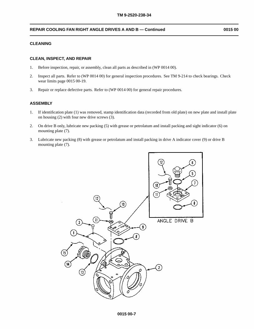
TM 9-2520-238-34
REPAIR COOLING FAN RIGHT ANGLE DRIVES A AND B — Continued 0015 00
CLEANING
CLEAN, INSPECT, AND REPAIR
1. Before inspection, repair, or assembly, clean all parts as described in (WP 0014 00).
2. Inspect all parts. Refer to (WP 0014 00) for general inspection procedures. See TM 9-214 to check bearings. Checkwear limits page 0015 00-19.
3. Repair or replace defective parts. Refer to (WP 0014 00) for general repair procedures.
ASSEMBLY
1. If identification plate (1) was removed, stamp identification data (recorded from old plate) on new plate and install plateon housing (2) with four new drive screws (3).
2. On drive B only, lubricate new packing (5) with grease or petrolatum and install packing and sight indicator (6) onmounting plate (7).
3. Lubricate new packing (8) with grease or petrolatum and install packing in drive A indicator cover (9) or drive Bmounting plate (7).
0015 00-7

TM 9-2520-238-34
REPAIR COOLING FAN RIGHT ANGLE DRIVES A AND B — Continued 0015 00
4. Install drive A indicator cover (9) or drive B mounting plate (7) on housing (2) as follows:
a. Clean threads of four cap screws (10). Apply a light coat of antiseize compound to threads.
b. Install drive A indicator cover (9) or drive B mounting plate (7) on housing (2) with four washers (11) and capscrews (10).
c. Tighten cap screws (10) to 42-48 lb-in (4.8-5.4 N•m) torque. Use torque wrench and socket set.
d. Install new lockwire (12) between four cap screws (10) using twist method. Use wire twister pliers.
5. Lubricate new packing (13) with grease or petrolatum and install packing on cap plug (14).
6. Install cap plug (14) in housing (2). Secure with new lockwire (15). Use wire twister pliers.
0015 00-8

TM 9-2520-238-34
REPAIR COOLING FAN RIGHT ANGLE DRIVES A AND B — Continued 0015 00
NOTE
Bevel gearshaft and bevel gear are a matched set and must be installed as a set.
7. Check that serial number etched on face of bevel gearshaft (1) matches serial number etched on bevel gear (2).
8. Record M.D. (Mounting Distance) dimension etched on face of bevel gearshaft (1) for later use in shimming cartridgeassembly (3).
NOTE
Matched duplex bearings stamped NEW DEPARTURE 0L07 or MCR107 must be installedwith thick sections of outer races facing each other. Matched duplex radial bearings stampedNEW DEPARTURE 3L07 must be installed with stamped faces toward outside of assembly.
9. Assemble cartridge assembly (3) as follows:
a. Measure length of sleeve spacer (4) and distance between bearing bores inside bearing housing (5). Use caliper set.
b. Peel laminated shim (6) to thickness to provide equal spacing between inner and outer races of bearings (7) and (8)within ± 0.001 inch (shim thickness + spacer length = distance between bearing bores inside housing). Use caliperset.
c. Install ball bearing (7), bevel gearshaft (1), sleeve spacer (4), laminated shim (6), and ball bearing (8) in bearinghousing (5).
d. Install new key washer (9) and round nut (10) on bevel gearshaft (1). Bend tang on key washer into slot on nut.
0015 00-9

TM 9-2520-238-34
REPAIR COOLING FAN RIGHT ANGLE DRIVES A AND B — Continued 0015 00
CAUTION
To prevent damage to encased oil seal, do not press seal beyond face of bore. After installationseal must be flush with outer surface.
10. Install new encased oil seal (11) in bearing retainer housing (12) as follows:
a. Clean mating surfaces of oil seal (11) and bearing retainer housing (12). Apply a thin film of sealing compound toouter edge of oil seal.
b. Press oil seal (11) into bearing retainer housing (12). Use arbor press.
11. Determine thickness of shim (1) as follows:
a. Without installing shim (1), install cartridge assembly (2) and bearing retainer housing (3) on housing (4) with fournew key washers (5) and cap screws (6). Tighten screws, but do not bend tabs on key washers at this time.
b. Measure inside diameter A in housing (4). Use caliper set.
c. Measure dimension B between inside edge of housing bore and unetched portion on face of bevel gearshaft. Usevernier height gage.
d. Calculate shim thickness using above measurements and M.D. dimension (etched on gearshaft) recorded in Step 8.Shim thickness = M.D. −A/2 + B.
e. Peel new laminated shim (1) to calculated thickness or next thinner laminate.
f. Remove four cap screws (6), key washers (5), bearing retainer housing (3), and cartridge assembly (2) fromhousing (4).
0015 00-10

TM 9-2520-238-34
REPAIR COOLING FAN RIGHT ANGLE DRIVES A AND B — Continued 0015 00
0015 00-11

TM 9-2520-238-34
REPAIR COOLING FAN RIGHT ANGLE DRIVES A AND B — Continued 0015 00
12. Lubricate new packing (7) with grease or petrolatum and install packing in groove in housing (4).
13. Lubricate new packing (8) with grease or petrolatum and install packing in bearing retainer housing (3).
14. Install cartridge assembly (2) in housing (4) as follows:
a. Clean threads of four cap screws (6). Apply a light coat of antiseize compound to threads.
b. Install laminated shim (1), cartridge assembly (2), and bearing retainer housing (3) on housing (4) and secure withfour key washers (5) and cap screws (6).
c. Tighten four cap screws (6) to 144-180 lb-in (17-20 N•m) torque. Use torque wrench and socket set.
d. Bend tabs on four key washers (5).
0015 00-12

TM 9-2520-238-34
REPAIR COOLING FAN RIGHT ANGLE DRIVES A AND B — Continued 0015 00
NOTE
Ball bearings are a matched set and both must be replaced if either is defective.
Matched duplex bearings stamped NEW DEPARTURE 0L07 or MCR107 must be installedwith thick sections of outer races facing each other. Matched duplex radial bearings stampedNEW DEPARTURE 3L07 must be installed with stamped faces toward outside of assembly.
15. Assemble spindle assembly (1) as follows:
a. Shouldered shaft (2) has left-hand threads at needle bearing end.
b. If orifice spring pin (3) was removed from shouldered shaft (2), install new pin in shaft with 1/16 to 1/8 inchprotruding from shaft.
c. Install machine key (4) in shouldered shaft (2).
d. Press bevel gear (5) on shouldered shaft (2). Use arbor press.
e. Install two matched ball bearings (6) in bearing housing (7).
f. Press two bearings (6) inside bearing housing (7) onto bevel gear (5). Use arbor press.
g. If needle bearing (8) was removed from shouldered shaft (2), install new needle bearing onto shaft and secure withretaining ring (9).
0015 00-13

TM 9-2520-238-34
REPAIR COOLING FAN RIGHT ANGLE DRIVES A AND B — Continued 0015 00
16. Determine thickness of shim (10) as follows:
a. Without installing shim (10), hold bearing retainer housing (11) firmly against bearing outer race in spindleassembly (1).
b. With a thickness gauge, measure gap between bearing retainer housing (11) and spindle assembly bearinghousing (7).
c. Peel new laminated shim (10) to nearest thickness smaller than gap measured in Step 16b.
d. Remove bearing retainer housing (11) from spindle assembly (1).
0015 00-14

TM 9-2520-238-34
REPAIR COOLING FAN RIGHT ANGLE DRIVES A AND B — Continued 0015 00
17. Determine initial thickness of shim (1) as follows:
a. Without installing shim (1), install spindle assembly (2), laminated shim (3), and bearing retainer housing (4) onhousing (5). Secure with four new key washers (6), and cap screws (7). Tighten screws only to the point wheregear backlash has been removed. Do not bend tabs on key washers at this time.
b. With a thickness gauge, measure gap between spindle assembly housing (8) and housing (5).
c. Calculate shim thickness using above measurement as follows: Shim thickness = Gap + 0.006
d. Peel new laminated shim (1) to calculated thickness or next thinner laminate. Keep removed laminates for later usein Step 18d below.
e. Remove four cap screws (7), key washers (6), bearing retainer housing (4), laminated shim (3), and spindleassembly (2) from housing (5).
0015 00-15

TM 9-2520-238-34
REPAIR COOLING FAN RIGHT ANGLE DRIVES A AND B — Continued 0015 00
18. Check and adjust backlash as follows:
a. Install laminated shim (1), spindle assembly (2), laminated shim (3), and bearing retainer housing (4) on housing (5)with four new key washers (6) and cap screws (7). Tighten screws, but do not bend tabs on key washers at this time.
b. Position housing (5) with shouldered shaft (9) in up position. Install backlash adjusting tool on shouldered shaft (9)and secure tool by tightening socket head screw on tool. Attach dial indicator so that indicator feeler fits in notchon arm of tool.
c. Check gear backlash by moving tool from side to side while observing dial indicator. Backlash reading should bebetween 0.002 inch and 0.004 inch.
d. If backlash is less than 0.002 inch, add more laminates to shim (1). If backlash is greater than 0.004 inch, removelaminates from shim.
e. If required, install new thickness shim and recheck backlash by repeating Steps 18a - 18c above.
f. Remove dial indicator and backlash adjusting tool from shouldered shaft (9).
g. Remove four cap screws (7), key washers (6), bearing retainer housing (4), laminated shim (3), and spindleassembly (2), and laminated shim (1) from housing (5).
0015 00-16

TM 9-2520-238-34
REPAIR COOLING FAN RIGHT ANGLE DRIVES A AND B — Continued 0015 00
CAUTION
To prevent damage to encased oil seal, do not press seal beyond face of bore. After installationseal must be flush with outer surface.
19. Install new encased oil seal (1) in bearing retainer housing (2) as follows:
a. Clean mating surfaces of oil seal (1) and bearing retainer housing (2). Apply a thin film of sealing compound toouter edge of oil seal.
b. Press oil seal (1) into bearing retainer housing (2). Use arbor press.
20. Lubricate new packing (3) with grease or petrolatum and install packing in groove in housing (4).
21. Lubricate new packing (5) with grease or petrolatum and install packing in bearing retainer housing (2).
0015 00-17

TM 9-2520-238-34
REPAIR COOLING FAN RIGHT ANGLE DRIVES A AND B — Continued 0015 00
22. Install spindle assembly (6) in housing (4) as follows:
a. Clean threads of four cap screws (7). Apply a light coat of antiseize compound to threads.
b. Install laminated shim (8), spindle assembly (6), laminated shim (9), and bearing retainer housing (2) on housing(4). Secure with four key washers (10) and cap screws (7).
c. Tighten four cap screws (7) to 144-180 lb-in (17-20 N•m) torque. Use torque wrench and socket set.
d. Bend tabs on four key washers (10).
23. Preserve drive as follows:
a. Fill drive with 5 ounces of engine oil. Check for leaks. See your (WP 0014 00).
b. Drain oil. Leave residual oil as preservative during shipping or storage.
24. Install pipe plug (11) in housing (4) as follows:
a. Clean male pipe threads thoroughly. Apply sealing compound to pipe threads. Do not apply sealant beyond smallend of threads. Do not fill leading thread.
b. Install plug (11) in housing (4).
0015 00-18

TM 9-2520-238-34
REPAIR COOLING FAN RIGHT ANGLE DRIVES A AND B — Continued 0015 00
WEAR LIMITS
1. Check parts that have reference letters in figure below.
2. Check the parts dimensions with chart on next page to determine replacement. Use micrometer, caliper set, and vernierheight gauge.
0015 00-19
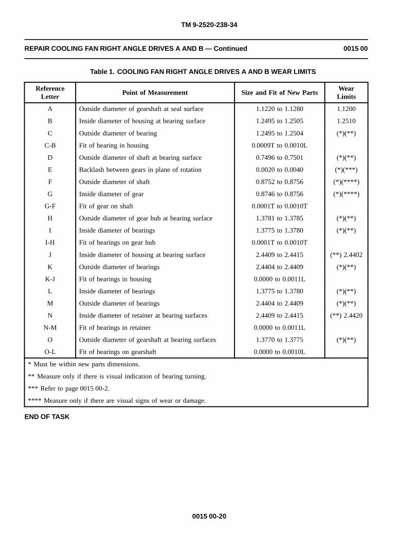
TM 9-2520-238-34
REPAIR COOLING FAN RIGHT ANGLE DRIVES A AND B — Continued 0015 00
Table 1. COOLING FAN RIGHT ANGLE DRIVES A AND B WEAR LIMITS
ReferenceLetter
Point of Measurement Size and Fit of New PartsWearLimits
A Outside diameter of gearshaft at seal surface 1.1220 to 1.1280 1.1200
B Inside diameter of housing at bearing surface 1.2495 to 1.2505 1.2510
C Outside diameter of bearing 1.2495 to 1.2504 (*)(**)
C-B Fit of bearing in housing 0.0009T to 0.0010L
D Outside diameter of shaft at bearing surface 0.7496 to 0.7501 (*)(**)
E Backlash between gears in plane of rotation 0.0020 to 0.0040 (*)(***)
F Outside diameter of shaft 0.8752 to 0.8756 (*)(****)
G Inside diameter of gear 0.8746 to 0.8756 (*)(****)
G-F Fit of gear on shaft 0.0001T to 0.0010T
H Outside diameter of gear hub at bearing surface 1.3781 to 1.3785 (*)(**)
I Inside diameter of bearings 1.3775 to 1.3780 (*)(**)
I-H Fit of bearings on gear hub 0.0001T to 0.0010T
J Inside diameter of housing at bearing surface 2.4409 to 2.4415 (**) 2.4402
K Outside diameter of bearings 2.4404 to 2.4409 (*)(**)
K-J Fit of bearings in housing 0.0000 to 0.0011L
L Inside diameter of bearings 1.3775 to 1.3780 (*)(**)
M Outside diameter of bearings 2.4404 to 2.4409 (*)(**)
N Inside diameter of retainer at bearing surfaces 2.4409 to 2.4415 (**) 2.4420
N-M Fit of bearings in retainer 0.0000 to 0.0011L
O Outside diameter of gearshaft at bearing surfaces 1.3770 to 1.3775 (*)(**)
O-L Fit of bearings on gearshaft 0.0000 to 0.0010L
* Must be within new parts dimensions.
** Measure only if there is visual indication of bearing turning.
*** Refer to page 0015 00-2.
**** Measure only if there are visual signs of wear or damage.
END OF TASK
0015 00-20

TM 9-2520-238-34
REPAIR COOLING FAN RIGHT ANGLE DRIVE C (M113A3 FOV ONLY) 0016 00
THIS WORK PACKAGE COVERS:
Disassembly (page 0016 00-20).Cleaning (page 0016 00-5).Assembly (page 0016 00-6).Wear Limits (page 0016 00-17).
INITIAL SETUP:
Maintenance Level
Direct Support
Tools and Special Tools
General mechanic’s tool kit (WP 0033 00, Item 37)
Bearing inserter (WP 0033 00, Item 1)
Micrometer caliper (WP 0033 00, Item 2)
Caliper gage set (WP 0033 00, Item 7)
Vernier height gage (WP 0033 00, Item 8)
Dial indicator (WP 0033 00, Item 11)
Dial indicator set (WP 0033 00, Item 13)
Hand arbor press (WP 0033 00, Item 16)
Socket wrench set, 3/8 inch drive,(WP 0033 00, Item 34)
Spanner socket (WP 0033 00, Item 35)
Torque wrench (WP 0033 00, Item 40)
Torque wrench (WP 0033 00, Item 41)
Backlash adjusting tool WP 0034 00, Item 1
Test stand WP 0034 00, Item 2
Materials/Parts
Antiseize compound (WP 0035 00, Item 1)
Engine lubricating oil (WP 0035 00, Item 5)
Grease (WP 0035 00, Item 6)
Petrolatum (WP 0035 00, Item 10)
Sealing compound (WP 0035 00, Item 12)
Sealing compound (WP 0035 00, Item 14)
Sealing compound (WP 0035 00, Item 15)
Wiping rags (WP 0035 00, Item 17)
Key washer
Oil seal
Oil seal
Preformed packing (4))
Preformed packing
Preformed packing
Preformed packing
Preformed packing
Preformed packing
Shim
Shim
Shim
Personnel Required
Track Vehicle Repairer
References
PMCSTM 9-2350-277-34TM 9-214
Equipment Condition
Cooling fan right angle drive removed from fanassembly (see your -34)
0016 00-1

TM 9-2520-238-34
REPAIR COOLING FAN RIGHT ANGLE DRIVE C (M113A3 FOV ONLY) — Continued 0016 00
DISASSEMBLY
CAUTION
Take care to prevent damage to machined surfaces, gears, bearings, and other componentsduring maintenance activities.
1. Remove screw (1) and copper washer (2) from housing (3) and drain oil into a suitable container.
2. Remove four bolts (4), washers (5), bearing and oil seal retainer (6), input cartridge assembly (7), and laminated shim (8)from housing (3). Discard shim.
3. Remove packing (9) from cartridge assembly (7). Discard packing.
4. Remove oil seal (10) and packing (11) from retainer (6). Discard oil seal and packing.
0016 00-2

TM 9-2520-238-34
REPAIR COOLING FAN RIGHT ANGLE DRIVE C (M113A3 FOV ONLY) — Continued 0016 00
5. Disassemble cartridge assembly (1) as follows:
a. Straighten tang on key washer (2). Remove round nut (3), key washer (2), and key washer (4) from shoulderedshaft (5). Use spanner socket. Discard key washer (2).
b. Press shouldered shaft (5) with attached bevel gear (6) out of inner race of bearing (7) in bearing retainer plate (8).Use arbor press.
c. Remove laminated shim (9) and sleeve spacer (10) from shouldered shaft (5). Discard shim.
d. Press inner race of bearing (11) and bevel gear (6) from shouldered shaft (5). Remove key (12). Use arbor press.
6. If inspection indicates tapered roller bearing (7) and tapered roller bearing (11) must be replaced, press outer races ofbearings out of retainer plate (8). Use arbor press. Discard outer races and inner races.
0016 00-3

TM 9-2520-238-34
REPAIR COOLING FAN RIGHT ANGLE DRIVE C (M113A3 FOV ONLY) — Continued 0016 00
7. Remove four bolts (13), washers (14), bearing and oil seal retainer (15), and bearing retaining plate (16) fromhousing (17).
8. Remove sleeve spacer (18) from spindle assembly (19).
9. Remove packing (20) and packing (21) from retaining plate (16). Discard packings.
10. Remove ball bearing (22) from bearing retaining plate (16). Use arbor press.
11. Press bearing sleeve (23) from ball bearing (22). Use arbor press.
12. Remove oil seal (24) from retainer (15). Discard oil seal.
0016 00-4

TM 9-2520-238-34
REPAIR COOLING FAN RIGHT ANGLE DRIVE C (M113A3 FOV ONLY) — Continued 0016 00
13. Remove four cap screws (1), washers (2), packings (3), spindle assembly (4), and laminated shim (5) from housing (6).Discard packings and shim.
NOTE
Do not attempt to remove tapered roller bearing from shaft. The bearing and shaft are amatched set. If bearing of shaft is damaged, obtain a new shaft and bearing from supply.
14. Disassemble spindle assembly (4) as follows:
a. Remove four cap screws (7) and washers (8).
b. Remove shaft and bearing (9) with attached parts from bearing retaining plate (10).
15. Remove liquid sight indicator (11) and packing (12) from housing (6). Discard packing.
16. Remove pipe plug (13) from housing (6).
17. If inspection indicates identification plate (14) must be replaced, remove four drive screws (15) and identification platefrom housing (6). Discard drive screws. Record identification data for use on new plate before discarding old plate.
CLEANING
CLEAN, INSPECT, AND REPAIR
1. Before inspection, repair, or assembly, clean all parts as described in (WP 0014 00).
2. Inspect all parts. Refer to (WP 0014 00) for general inspection procedures. See TM 9-214 to check bearings. Checkwear limits page 0016 00-17.
3. Repair or replace defective parts. Refer to (WP 0014 00) for general repair procedures.
0016 00-5

TM 9-2520-238-34
REPAIR COOLING FAN RIGHT ANGLE DRIVE C (M113A3 FOV ONLY) — Continued 0016 00
ASSEMBLY
1. If identification plate (14) was removed, stamp identification data (recorded from old plate) on new plate and install plateon housing (6) with four new drive screws (15).
2. Install liquid sight indicator (11) as follows:
a. Lubricate new packing (12) with grease or petrolatum and install on liquid sight indicator (11).
b. Apply a light coat of antiseize compound to threads of sight indicator (11). Install sight indicator in housing (6).
0016 00-6

TM 9-2520-238-34
REPAIR COOLING FAN RIGHT ANGLE DRIVE C (M113A3 FOV ONLY) — Continued 0016 00
3. Assemble spindle assembly (1) as follows:
a. Install shaft and bearing (2) with attached parts in bearing retaining plate (3).
b. Apply a light coat of antiseize compound to threads of four cap screws (4).
c. Secure retaining plate (5) on shaft and bearing (2) to retaining plate (3) with four washers (6) and cap screws (4).
d. Tighten four cap screws (4) to 96-108 lb-in (11-12 N•m) torque. Use torque wrench (WP 0034 00, Item 40) andsocket set.
0016 00-7

TM 9-2520-238-34
REPAIR COOLING FAN RIGHT ANGLE DRIVE C (M113A3 FOV ONLY) — Continued 0016 00
NOTE
Take all measurements in thousandths of an inch.
4. Determine thickness of shim (7) as follows:
a. Place spindle assembly (1) on clean, flat surface. Measure from top of pinion gear (8) to surface and from bottomof pinion gear to surface. Subtract second reading from first. Record as dimension C. Use caliper set and dialindicator (WP 0033 00, Item 11).
b. Record Mounting Distance (M.D.) etched on pinion gear (8).
c. Measure inside diameter of bore in housing (9) and record as dimension A. Use caliper set.
d. Without installing shim (7), install spindle assembly (1) inside housing (9).
e. Place housing (9) on clean, flat surface. Measure from top of pinion gear (8) to surface and from edge of bore inhousing to surface. Subtract second reading from first. Record as dimension B. Use caliper set and dial indicator(WP 0033 00, Item 11).
f. Calculate shim thickness using above measurements and M.D. dimension (etched on pinion gear). Shim thickness= A/2 – B + C – M.D.
g. Peel new laminated shim (7) to calculated thickness or next thinner laminate. Keep removed laminates for later usein Step 21 below.
h. Remove spindle assembly (1) from housing (9).
0016 00-8
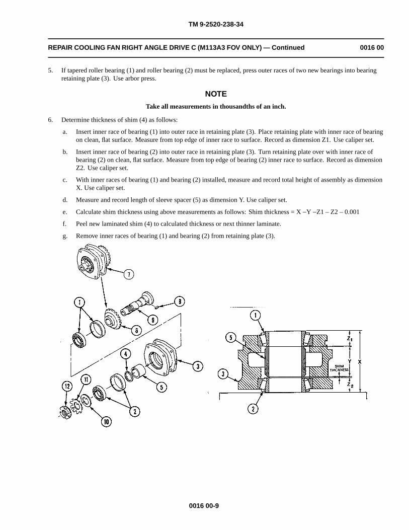
TM 9-2520-238-34
REPAIR COOLING FAN RIGHT ANGLE DRIVE C (M113A3 FOV ONLY) — Continued 0016 00
5. If tapered roller bearing (1) and roller bearing (2) must be replaced, press outer races of two new bearings into bearingretaining plate (3). Use arbor press.
NOTE
Take all measurements in thousandths of an inch.
6. Determine thickness of shim (4) as follows:
a. Insert inner race of bearing (1) into outer race in retaining plate (3). Place retaining plate with inner race of bearingon clean, flat surface. Measure from top edge of inner race to surface. Record as dimension Z1. Use caliper set.
b. Insert inner race of bearing (2) into outer race in retaining plate (3). Turn retaining plate over with inner race ofbearing (2) on clean, flat surface. Measure from top edge of bearing (2) inner race to surface. Record as dimensionZ2. Use caliper set.
c. With inner races of bearing (1) and bearing (2) installed, measure and record total height of assembly as dimensionX. Use caliper set.
d. Measure and record length of sleeve spacer (5) as dimension Y. Use caliper set.
e. Calculate shim thickness using above measurements as follows: Shim thickness = X −Y −Z1 – Z2 – 0.001
f. Peel new laminated shim (4) to calculated thickness or next thinner laminate.
g. Remove inner races of bearing (1) and bearing (2) from retaining plate (3).
0016 00-9

TM 9-2520-238-34
REPAIR COOLING FAN RIGHT ANGLE DRIVE C (M113A3 FOV ONLY) — Continued 0016 00
7. Measure and record the thickness of bevel gear (6) as dimension C. Use caliper set.
8. Record Mounting Distance (M.D.) etched on bevel gear (6).
9. Assemble cartridge assembly (7) as follows:
a. Install key (8) on shouldered shaft (9), and press bevel gear (6) on shaft. Use arbor press.
b. Press inner race of bearing (1) on shaft (9). Use arbor press.
c. Install shaft (9) with bevel gear (6) and inner race of bearing (1) in retaining plate (3).
d. Install sleeve spacer (5) and peeled shim (4) on shaft (9) in retaining plate (3).
e. Press inner race of bearing (2) on shaft (9) in retaining plate (3). Use arbor press.
f. Install key washer (10), new key washer (11), and round nut (12) on shaft (9). Use spanner socket.
g. Bend tang on key washer (11) into slot on nut (12).
0016 00-10

TM 9-2520-238-34
REPAIR COOLING FAN RIGHT ANGLE DRIVE C (M113A3 FOV ONLY) — Continued 0016 00
NOTE
Install cartridge assembly with the word TOP facing up.
10. Determine thickness of shim (1) as follows:
a. Without installing laminated shim (1), install cartridge assembly (2) and retainer (3) on housing (4) with fourwashers (5) and bolts (6). Tighten bolts snug.
b. Measure and record inside diameter of bore in housing (4) as dimension A. Use caliper set.
c. Place housing (4) on clean, flat surface. Measure from face of bevel gear (7) to surface and from edge of bore inhousing to surface. Subtract second reading from first. Record as dimension B. Use caliper set and dial indicator(WP 0033 00, Item 11).
d. Calculate shim thickness using above measurements, dimension C recorded in (Step 7), and M.D. dimension(etched on bevel gear) recorded in (Step 8). Shim thickness = M.D. −A/2 + B – C
e. Peel new laminated shim (1) to calculated thickness or next thinner laminate. Keep removed laminates for later usein (Step 21) below.
f. Remove four bolts (6), washers (5), retainer (3), and cartridge assembly (2) from housing (4).
0016 00-11

TM 9-2520-238-34
REPAIR COOLING FAN RIGHT ANGLE DRIVE C (M113A3 FOV ONLY) — Continued 0016 00
11. Install spindle assembly (8) in housing (4) as follows:
a. Apply a coat of antiseize compound to threads of four cap screws (9).
b. Install peeled shim (10) and spindle assembly (8) in housing (4).
c. Lubricate four new packings (11) with grease or petrolatum.
d. Secure shim (10) and spindle assembly (8) to housing (4) with four packings (11), washers (12), and cap screws (9).
e. Tighten four cap screws (9) to 384-408 lb-in torque (44-46 N•m). Use torque wrench (WP 0033 00, Item 41) andsocket set.
0016 00-12

TM 9-2520-238-34
REPAIR COOLING FAN RIGHT ANGLE DRIVE C (M113A3 FOV ONLY) — Continued 0016 00
12. Install sleeve spacer (1) on shaft and bearing (2).
13. Press bearing sleeve (3) into ball bearing (4) and install ball bearing into bearing retaining plate (5). Use arbor press.
CAUTION
To prevent damage to oil seal, do not press seal beyond face of bore. After installation seal mustbe flush with outer surface.
14. Lubricate new packing (6) and new packing (7) with grease or petrolatum. Install packings in bearing retaining plate (5).
15. Install new oil seal (8) and oil seal (9) into oil seal retainer (10) and oil seal retainer (11) as follows:
a. Clean mating surfaces of oil seal (8), oil seal (9), oil seal retainer (10), and oil seal retainer (11). Apply a thin filmof sealing compound (WP 0035 00, Item 12) or (WP 0035 00, Item 15) to outer edge of oil seals.
b. Press oil seal (8) and oil seal (9) into retainer (10) and retainer (11). Use arbor press.
0016 00-13

TM 9-2520-238-34
REPAIR COOLING FAN RIGHT ANGLE DRIVE C (M113A3 FOV ONLY) — Continued 0016 00
16. Install bearing retainer plate (5) on housing (12) as follows:
a. Apply a coat of antiseize compound to threads of four bolts (13).
b. Install bearing retaining plate (5) and oil seal retainer (10) on housing (12) and secure with four washers (14) andbolts (13).
c. Tighten four bolts (13) to 194-228 lb-in (22-25 N•m) torque. Use torque wrench (WP 0033 00, Item 41) and socketset.
17. Lubricate new packing (15) with grease or petrolatum. Install packing in groove on cartridge assembly (16).
18. Lubricate new packing (17) with grease or petrolatum. Install packing in groove on oil seal retainer (11).
NOTE
Install cartridge assembly with the word TOP facing up.
19. Install cartridge assembly (16) on housing (12) as follows:
a. Apply a coat of antiseize compound to threads of four bolts (18).
b. Install peeled shim (19), cartridge assembly (16), and oil seal retainer (11) on housing (12) and secure with fourwashers (20) and bolts (18).
c. Tighten four bolts (18) to 194-228 lb-in (22-25 N•m) torque. Use torque wrench (WP 0033 00, Item 41) and socketset.
20. Install copper washer (21) and screw (22) in drain hole in housing (12).
0016 00-14

TM 9-2520-238-34
REPAIR COOLING FAN RIGHT ANGLE DRIVE C (M113A3 FOV ONLY) — Continued 0016 00
21. Check and adjust backlash between gears as follows:
a. Install housing (1) in test stand with spindle shaft (2) in up position. Install backlash adjusting tool on spindle shaft(2) and secure tool by tightening socket head screw on tool. Attach dial indicator (WP 0033 00, Item 13) so thatindicator feeler fits in notch on arm of tool.
b. Check gear backlash by moving tool from side to side while observing dial indicator. Backlash reading should bebetween 0.005 inch and 0.009 inch.
c. If backlash is less than 0.005 inch, remove more laminates from spindle shim (3) or add laminates to cartridgeshim (4).
d. If backlash is greater than 0.009 inch, add laminates to spindle shim (3) or remove laminates from cartridgeshim (4).
e. If required, remove cartridge assembly (5) and spindle assembly (6), install new thickness shim (3) and newthickness shim (4), and repeat Step 11, Step 16, and Step 19. Then recheck backlash by repeating steps Step 21aand Step 21b above.
f. Remove dial indicator and backlash adjusting tool from spindle shaft (2).
0016 00-15

TM 9-2520-238-34
REPAIR COOLING FAN RIGHT ANGLE DRIVE C (M113A3 FOV ONLY) — Continued 0016 00
22. Preserve drive as follows:
a. Fill drive with 5 ounces of engine oil. Check for leaks. See your (WP 0014 00).
b. Remove screw (7) and copper washer (8) from housing (1) and drain oil into a suitable container. Leave residual oilas preservative during shipping or storage.
c. Apply a coat of antiseize compound to threads of screw (7).
d. Install copper washer (8) and screw (7) in drain hole in housing (1).
e. Tighten screw (7) to 192-240 lb-in (22-27 N•m) torque. Use torque wrench (WP 0033 00, Item 41) and socket set.
23. Install pipe plug (9) in housing (1) as follows:
a. Clean male pipe threads thoroughly. Apply sealing compound (WP 0035 00, Item 12) to pipe threads. Do notapply sealant beyond small end of threads. Do not fill leading thread.
b. Install plug (9) in housing (1).
0016 00-16

TM 9-2520-238-34
REPAIR COOLING FAN RIGHT ANGLE DRIVE C (M113A3 FOV ONLY) — Continued 0016 00
WEAR LIMITS
1. Check parts that have reference letters in figure below.
2. Check the parts dimensions with chart on next page to determine replacement. Use micrometer, caliper set, and vernierheight gauge.
0016 00-17

TM 9-2520-238-34
REPAIR COOLING FAN RIGHT ANGLE DRIVE C (M113A3 FOV ONLY) — Continued 0016 00
Table 1. COOLING FAN RIGHT ANGLE DRIVE C WEAR LIMITS
ReferenceLetter
Point of Measurement Size and Fit of New PartsWearLimits
A Outside diameter of shouldered shaft at seal surface 1.1220 to 1.1270 1.1200
B Inside diameter of bearing retainer plate 2.1654 to 2.1666 2.1671
C Outside diameter of ball bearing 2.1649 to 2.1654 (*)(**)
C-B Fit of ball bearing in bearing retainer plate 0.0000 to 0.0017L
D Outside diameter of bearing sleeve 1.1814 to 1.1818 (*)(**)
E Inside diameter of ball bearing 1.1807 to 1.1811 (*)(**)
E-D Fit of ball bearing on bearing sleeve 0.0003T to 0.0011T
F Backlash between gears in plane of rotation 0.0050 to 0.0090 (*)(***)
G Outside diameter of tapered roller bearing 2.4409 to 2.4419 (*)(**)
H Inside diameter of bearing retainer plate 2.4429 to 2.4439 (*)(**)
H-G Fit of tapered roller bearing in retainer plate 0.0010T to 0.0020L
I Inside diameter of pinion gear 0.9375 to 0.9380 (*)(****)
J Outside diameter of shouldered shaft at gear surface 0.9380 to 0.9385 (*)(****)
J-I Fit of pinion gear on shouldered shaft 0.0000 to 0.0010T
K Inside diameter of bearing sleeve 0.8760 to 0.8770 (*)(****)
L Outside diameter of shouldered shaft at sleeve surface 0.8752 to 0.8756 (*)(****)
L-K Fit of bearing sleeve on shouldered shaft 0.0004L to 0.0018L
M Outside diameter of shouldered shaft at seal surface 0.8752 to 0.8756 0.8732
N Inside diameter of tapered roller bearing 1.3775 to 1.3780 (*)(**)
O Outside diameter of shouldered shaft at bearing surface 1.3785 to 1.3790 (*)(****)
O-N Fit of tapered roller bearing on shouldered shaft 0.0005T to 0.0015T
P Inside diameter of bevel gear 1.4375 to 1.4380 (*)(****)
Q Outside diameter of shouldered shaft at gear surface 1.4380 to 1.4385 (*)(****)
Q-P Fit of bevel gear on shouldered shaft 0.0000 to 0.0010T
R Outside diameter of tapered roller bearing 2.3612 to 2.3622 (*)(**)
S Inside diameter of bearing retainer plate 2.3588 to 2.3598 2.3603
S-R Fit of tapered roller bearing in retainer plate 0.0014T to 0.0034T
* Must be within new parts dimensions.
** Measure only if there is visual indication of bearing turning.
*** Refer to repair cooling fans right angle drive A and B (WP 0015 00).
**** Measure only if there are visual signs of wearing or damage.
END OF TASK
0016 00-18

TM 9-2520-238-34
CHAPTER 5
DIRECT SUPPORT MAINTENANCE INSTRUCTIONSFOR REPAIR TRANSFER GEARCASES
WORK PACKAGE INDEX
Title Sequence No.
REPAIR TRANSFER GEARCASES A, B, AND C.........................................................................................................0017 00
REPLACE TRANSFER GEARCASE A, B, OR C WITH SERVICE SPARE TRANSFERGEARCASE E..........................................................................................................................................................0018 00
REPAIR TRANSFER GEARCASE F...............................................................................................................................0019 00


TM 9-2520-238-34
REPAIR TRANSFER GEARCASES A, B, AND C 0017 00
THIS WORK PACKAGE COVERS:
Disassembly (page 0017 00-2).Cleaning (page 0017 00-12).Assembly (page 0017 00-13).Run-In Test (page 0017 00-25).Wear Limits (page 0017 00-26).
INITIAL SETUP:
Maintenance Level
Direct Support
Tools and Special Tools
General mechanic’s tool kit (WP 0033 00, Item 37)
Bearing cup replacer (WP 0033 00, Item 27)
Mechanical puller kit (WP 0033 00, Item 17)
Portable electrical drill (WP 0033 00, Item 4)
Remover/replacer (WP 0033 00, Item 21)
Jack screw (4) (WP 0033 00, Item 30)
Screwdriver bit set and handle (WP 0033 00, Item 31)
Sling (WP 0033 00, Item 32)
Soft plastic hammer (WP 0033 00, Item 10)
Torque wrench (WP 0033 00, Item 41)
Torque wrench (WP 0033 00, Item 44)
Twist drill set (WP 0033 00, Item 5)
Materials/Parts
Antisieze compound (WP 0035 00, Item 1)
Engine lubricating oil (WP 0035 00, Item 5)
Grease (WP 0035 00, Item 6)
Petrolatum (WP 0035 00, Item 10)
Sealing compound (WP 0035 00, Item 12)
Sealing compound (WP 0035 00, Item 13)
Transfer gearcase parts kit
Cotter pin
Cotter pin
Grooved pin
Plug
Preformed packing
Preformed packing
Solid rivet
Spring pin
Personnel Required
Track Vehicle Repairer
References
See your -20See your -34See your -34PSee your PMCSTM 9-214
Equipment Condition
Power plant removed (see your -20)
Power plant blocked (see your -34)
Transmission removed from transfer gearcase A, B, or C(see your -34)
Transfer gearcase A, B, or C removed from engine (seeyour -34)
0017 00-1
Machine key

TM 9-2520-238-34
REPAIR TRANSFER GEARCASES A, B, AND C — Continued 0017 00
DISASSEMBLY
WARNING
Lifting or moving objects in excess of 70 pounds could injure you. Make sure to get an assistantor use a lifting device to move heavy objects.
CAUTION
Take care to prevent damage to machined surfaces, gears, bearings, and other componentsduring maintenance activities.
1. Lift transfer gearcase A, B, or C using suitable hoist and beam type sling, through eye bolt (1) and place gearcase in
2. Remove oil drain plug (2) and packing (3) from housing (4). Drain oil from housing into a suitable container. Discardpacking.
3. Remove eye bolt (1) from housing (4).
0017 00-2
work station. Remove sling and hoist from eyebolt.

TM 9-2520-238-34
REPAIR TRANSFER GEARCASES A, B, AND C — Continued 0017 00
4. Remove liquid level gauge rod (1) from guide (2). Remove guide (2), packing (3), and guide (4) from housing (5).Discard packing.
5. Remove cap screw (6), and washer (7). On gearcase A, remove two-groove pulley (8). On gearcase B or C, removethree-groove pulley (9). Remove machine key (10) from hub of second intermediate gear. Discard machine key.
6. On gearcase A, B, or C, remove ramp hydraulic pump (11) from cover on housing (5). Remove hex nut (12), elbow (13),washer (14), and packing (15) from pump (11). Discard packing. Straighten tabs on two key washers (16). Remove twomachine bolts (17) and key washers (16), and remove pump with bracket (18) and packing (19) from cover. Discard keywashers and packing.
0017 00-3

TM 9-2520-238-34
REPAIR TRANSFER GEARCASES A, B, AND C — Continued 0017 00
7. Remove coupling (20) from hub of secondary pump drive gear.
8. Remove lock wire (21) and four cap screws (22). Separate pump (11), bracket (18), and gasket (23). Discard lock wireand gasket.
9. Remove retaining ring (24) from pump shaft. Discard retaining ring.
10. Straighten tabs on two key washers (28). Remove two cap screws (29), key washers (28) and cover (26) from housingcover. Discard key washers.
11. Remove packing (30) from cover (26). Discard packing.
0017 00-4

TM 9-2520-238-34
REPAIR TRANSFER GEARCASES A, B, AND C — Continued 0017 00
12. Remove cotter pin (1), slotted nut (2), and one or two washers (3) securing differential oil pump to secondary pumpdrive-gear. Discard cotter pin. Straighten tabs on two key washers (4). Remove two cap screws (5), key washers (4) anddifferential oil pump (6). Remove and discard machine key (7) and gasket (8).
13. If pump (6) is to be replaced, remove retaining ring (9) from shaft of pump. Discard retaining ring.
14. Remove and discard solid rivet (10) holding filler neck (11) in housing (12). Remove filler neck. Remove two helicalsprings (13) and spring pin (14) holding cap to filler cap head. Discard pin. Remove and discard packing (15).
0017 00-5
NOTEThis is an internal gear and is notremoved here. This is only shown
as a reference for the pump installation.

TM 9-2520-238-34
REPAIR TRANSFER GEARCASES A, B, AND C — Continued 0017 00
NOTE
If needed, remove the following components.
15. Remove two cap screws (16) and cover (17) from housing (12).
16. Remove resilient mount (18) from housing (12) using remover and replacer shown.
17. On gearcase A, B, or C, remove groove pin (19) and manual remote control lever (20) from engine disconnect actuator.Discard pin.
18. Remove generator drive assembly (21) or generator drive assembly (22). Straighten tabs on four key washers (23).Remove four cap screws (24) and key washers (23).
19. Remove shim (25) from cover and packing (26) from generator drive (21) or generator drive (22). Discard shim andpacking.
0017 00-6
NOTEThis is an internal gear and is notremoved here. This is only shown
as a reference for the pump installation.

TM 9-2520-238-34
REPAIR TRANSFER GEARCASES A, B, AND C — Continued 0017 00
20. Remove cotter pin (1) and washer (2) from engine disconnect actuator (3). Separate actuator from shift collar (4).Discard cotter pin. Remove retaining ring (5), retaining ring (6), ball bearing (7), shift collar (4), and input shoulderedshaft (8) from housing. Discard retaining rings. Remove encased oil seal (9) from housing. Discard oil seal.
21. Straighten tabs on key washer (10). Remove cap screw (11), key washer (10), gearcase washer assembly (12), and diskassembly (13) from output gear. Discard key washer. Remove encased oil seal (14), dirt deflector (15), and packing (16)from disk assembly (13). Discard oil seal, dirt deflector, and packing.
0017 00-7
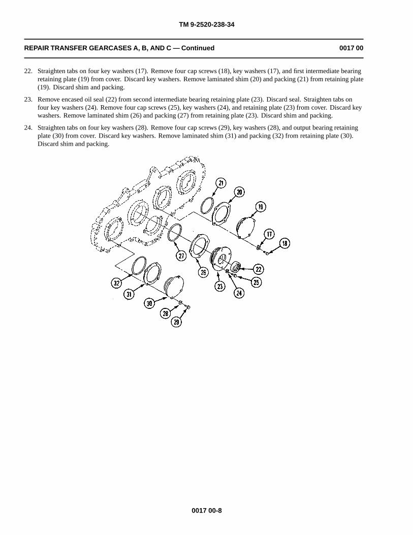
TM 9-2520-238-34
REPAIR TRANSFER GEARCASES A, B, AND C — Continued 0017 00
22. Straighten tabs on four key washers (17). Remove four cap screws (18), key washers (17), and first intermediate bearingretaining plate (19) from cover. Discard key washers. Remove laminated shim (20) and packing (21) from retaining plate(19). Discard shim and packing.
23. Remove encased oil seal (22) from second intermediate bearing retaining plate (23). Discard seal. Straighten tabs onfour key washers (24). Remove four cap screws (25), key washers (24), and retaining plate (23) from cover. Discard keywashers. Remove laminated shim (26) and packing (27) from retaining plate (23). Discard shim and packing.
24. Straighten tabs on four key washers (28). Remove four cap screws (29), key washers (28), and output bearing retainingplate (30) from cover. Discard key washers. Remove laminated shim (31) and packing (32) from retaining plate (30).Discard shim and packing.
0017 00-8

TM 9-2520-238-34
REPAIR TRANSFER GEARCASES A, B, AND C — Continued 0017 00
25. To disassemble generator drive assembly (1) on gearcases A or B, remove retaining ring (2) from hub of generator drivepulley (3). On gearcase C, remove retaining ring (2) from hub of drive pulley (4). Separate pulley (3) or pulley (4) frombearing retaining plate (5). Discard retaining ring. Remove retaining ring (6), ball bearing (7), sleeve spacer (8), ballbearing (9), and retaining ring (10) from bearing retaining plate (5). Discard retaining ring (6) and retaining ring (10).Remove and discard oil seal (11) from retaining plate (5). Remove and discard plug (12) from pulley (3) or pulley (4).
NOTE
Do not remove tapered roller bearing cups that are pressed in retaining plates unless inspectionindicates a replacement is needed.
26. As needed, use a mechanical puller kit and remove bearing cup(s) from retaining plate (5), or retaining plate (13), or retaining plate (14), or retaining plate (15).
0017 00-9
GEARCASE B AND CGEARCASE B AND C
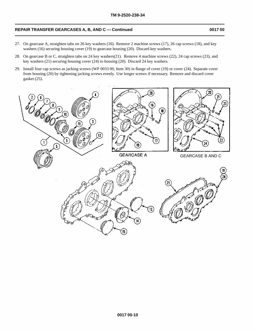
TM 9-2520-238-34
REPAIR TRANSFER GEARCASES A, B, AND C — Continued 0017 00
27. On gearcase A, straighten tabs on 26 key washers (16). Remove 2 machine screws (17), 26 cap screws (18), and keywashers (16) securing housing cover (19) to gearcase housing (20). Discard key washers.
28. On gearcase B or C, straighten tabs on 24 key washers(21). Remove 4 machine screws (22), 24 cap screws (23), andkey washers (21) securing housing cover (24) to housing (20). Discard 24 key washers.
29. Install four cap screws as jacking screws (WP 0033 00, Item 30) in flange of cover (19) or cover (24). Separate coverfrom housing (20) by tightening jacking screws evenly. Use longer screws if necessary. Remove and discard covergasket (25).
0017 00-10
GEARCASE B AND C

TM 9-2520-238-34
REPAIR TRANSFER GEARCASES A, B, AND C — Continued 0017 00
30. If inspection indicates damage, remove alignment pin(s) (1) from housing (2). Discard pin(s)
NOTE
Do not remove tapered roller bearing cones or cups that are pressed in place unless inspectionindicates a replacement is needed.
31. Remove output gear (3) from housing (2). Separate bearing cone (4) and bearing cone (5) from gear.
32. Remove helical gearshaft cluster (6) as an assembly from housing (2). Separate bearing cone (7) and bearing cone (8)from cluster. If replacement is needed, use brass drift pin and hammer to remove spring pin (9). Separate primarypump-drive gear (10) from second intermediate gear (11). Discard spring pin.
0017 00-11

TM 9-2520-238-34
REPAIR TRANSFER GEARCASES A, B, AND C — Continued 0017 00
33. Remove first intermediate gear (12) from housing (2). Separate bearing cone (13) and bearing cone (14) from gear.
34. Remove secondary pump-drive gear (15) from housing (2).
35. Remove input gear (16) from housing (2). Separate bearing cone (17) and bearing cone (18) from gear.
36. If needed, remove bearing cup (19) and bearing cup (20) from cover (21) and housing (2) with hammer and punch.Discard cups.
CLEANING
CLEAN, INSPECT, AND REPAIR
1. Inspect all parts of the transfer gearcase. See (WP 0014 00) for general inspection and repair procedures. Check wearlimits on transfer gearcases A, B, and C page 0017 00-26. Repair or replace defective parts as needed.
0017 00-12

TM 9-2520-238-34
REPAIR TRANSFER GEARCASES A, B, AND C — Continued 0017 00
ASSEMBLY
CAUTION
Do not weld aluminum castings. If replacement of a bearing cup or cone is required, itsassociated cup or cone must also be replaced. The gearcase mechanical housing includes thehousing and cover. They are machined as a unit and must be replaced as an assembly.
1. If bearing cup (1) was removed during disassembly, install new bearing cup in housing (2). Heat bearing bore to250-300�F (121-158�C), and freeze bearing cup. Position bearing cup to its associated bearing bore. Using bearing cupreplacer and soft plastic hammer, tap cup in place.
NOTE
If roller bearing cones were removed during disassembly, install new ones. New cones may beheated in oil to 250�F (121�C) to aid installation.
2. Place gearcase housing (2) flat on smooth surface with cover side up.
3. If removed, install bearing cone (3) and bearing cone (4) on input gear (5). Install gear in housing (2).
4. Install secondary pump-drive gear (6) in housing (2) with smaller diameter hub toward housing.
5. If removed, install bearing cone (7) and bearing cone (8) on first intermediate gear (9). Install gear in housing (2)meshing teeth with input gear (5).
0017 00-13

TM 9-2520-238-34
REPAIR TRANSFER GEARCASES A, B, AND C — Continued 0017 00
0017 00-14

TM 9-2520-238-34
REPAIR TRANSFER GEARCASES A, B, AND C — Continued 0017 00
NOTE
Check that mating surfaces of second intermediate gear and primary pump-drive gear areclean. Alignment of gear teeth is not necessary.
6. Assemble helical gearshaft cluster (1). If dowel holes exist in second intermediate gear (2) and primary pump-drive gear(3), align holes in each gear. Secure gears together with new spring pin (4). Stake pin three equal places at both ends. Ifdowel holes do not exist in either gears (2) or (3), assemble gears and drill a 0.375 to 0.380 inch diameter hole using a 3/8 inch drill. Secure gear (2) and gear (3) together with new spring pin (4). Stake pin three equal places at both ends.
7. If removed, install bearing cone (5) and bearing cone (6) on helical gearshaft cluster (1). Install cluster in housing (7)meshing teeth of second intermediate gear (2) with first intermediate gear (8).
8. If removed, install bearing cone (9) and bearing cone (10) on output gear (11). Install gear in housing (7) meshing teethwith second intermediate gear (2).
0017 00-15

TM 9-2520-238-34
REPAIR TRANSFER GEARCASES A, B, AND C — Continued 0017 00
CAUTION
Gearcase cover and housing are machined as a unit and must be replaced as a matched set.
9. Install housing cover (12) or housing cover (13) on housing (7). If removed, install new alignment pin(s) (14) in housing.Tap in place using soft plastic hammer. Install new gasket (15) on housing (7). Align cover (12) or cover (13) with fourpins (14) and place cover on housing.
10. On gearcase B or C, install housing cover (12). Apply a light coat of antiseize compound to clean threads of 24 capscrews (16) and 4 machine screws (17). Install cover (12) on housing (7) with 24 new key washers (18), cap screws (16),and 4 machine screws (17). Tighten 24 cap screws (16) and 4 machine screws (17) to 144-192 lb-in (17-21 N•m) torque.Use torque wrench (WP 0033 00, Item 41). Bend tabs on 24 key washers (18).
11. On gearcase A, install housing cover (1). Apply a light coat of antiseize compound to clean threads of 26 cap screws (2)and 2 machine screws (3). Install cover (1) on housing (4) with 26 new key washers (5), cap screws (2), and 2 machinescrews (3). Torque 26 cap screws (2) and 2 machine screws (3) to 144-192 lb-in (17-21 N•m). Use torque wrench(WP 0033 00, Item 41). Bend tabs on 26 key washers (5).
0017 00-16
GEARCASE B AND CGEARCASE B AND C

TM 9-2520-238-34
REPAIR TRANSFER GEARCASES A, B, AND C — Continued 0017 00
12. Lubricate new packing (6) with grease or petrolatum, and install packing on shaft of disk assembly (7).
13. Install new dirt deflector (8) in gearcase housing.
CAUTION
To prevent damage to encased oil seal, do not press seal beyond face of bore. After installationseal must be flush with outer surface.
14. Install new encased oil seal (9). Apply a thin even film of sealing compound (WP 0035 00, Item 12) or (WP 0035 00,Item 13) to clean mating surface of seal. Apply a thin even film of sealing compound (WP0035 00, Item 12 or 13) tothe outside edge of seal to prevent leaking. Position seal with lip toward bore. Use a flat block of wood and soft
15. Align splines of disk assembly (7) with splines of output gear and insert disk assembly shaft into output gear.
16. Clean threads of cap screw (10). Apply a light coat of antiseize compound to screw threads. Secure disk assembly (7)with gearcase washer assembly (11), new key washer (12), and cap screw (10). Torque screw to 360-420 lb-in (41-47N•m). Use torque wrench (WP 0033 00, Item 41). Bend tabs on key washers.
0017 00-17
plastic hammer and tap seal in place.

TM 9-2520-238-34
REPAIR TRANSFER GEARCASES A, B, AND C — Continued 0017 00
CAUTION
To prevent damage to encased oil seal, do not press seal beyond face of bore. After installationseal must be flush with outer surface.
17. Install new encased oil seal (13). Apply a thin even film of sealing compound (WP 0035 00, Item 12) or (WP 0035 00,Item 13) to clean mating surface of seal. Position seal with lip toward bore. Use a flat block of wood and mallet and tapseal in place.
18. Insert engine disconnect actuator (14) through hole in top of gearcase housing. Secure to housing bracket with washer(15) and new cotter pin (16).
19. Insert ball bearing (17) into shift collar (18). Secure in place with new retaining ring (19).
20. Install shift collar (18) on input shouldered shaft (20). Secure with new retaining ring (21).
21. Align splines of input shaft (20) with input gear. Install input shaft with shift collar (18) aligned with actuator (14).
0017 00-18

TM 9-2520-238-34
REPAIR TRANSFER GEARCASES A, B, AND C — Continued 0017 00
22. If removed, install bearing cups (1) in retaining plate (2), or retaining plate (3), or retaining plate (4), or retaining plate(5) with bearing cup replacer and a soft plastic hammer.
23. Install new encased oil seal (6) in second intermediate bearing retaining plate (3). Apply a thin even film of sealingcompound (WP 0035 00, Item 12) or (WP 0035 00, Item 13) to clean mating surface of seal. Position seal with liptoward bore. Use a flat block of wood and mallet and tap seal in place so that top surface is .09 to .15 inch below surfaceof retaining plate.
NOTE
Install bearing retaining plate with oil hole up. Most retaining plates have the word TOPmarked on metal near oil hole.
24. Determine thickness of new laminated shim (7) for bearing preload. Without shim and four new key washers (8)installed, place output bearing retaining plate (4) on gearcase cover. Lube four cap screws (9) with engine oil. Secureplate to cover with screws. Tighten screws (9) uniformly to 14–16 lb-in (1.5–1.8 N•m) torque. Use torque wrench(WP 0033 00, Item 41). Rotate gear train by hand one revolution in each direction to check freedom of movement.Recheck installation procedures if binding is detected.
0017 00-19

TM 9-2520-238-34
REPAIR TRANSFER GEARCASES A, B, AND C — Continued 0017 00
NOTE
Ensure that the secondary pump-drive gear does not interfere with gear rotation. This gear isnonfunctional until the differential oil pump is installed.
25. Using a thickness gauge, measure the gap between bearing retaining plate (4) and gearcase cover at three equal placesaround cover. Determine the average of these readings and record.
26. Peel laminated shim (7) to 0.003-0.005 inch less than the average recorded in step above.
27. Remove four cap screws (9) and retaining plate (4) from gearcase cover.
28. Repeat Steps 24 - 27 above using retaining plate (2), retaining plate (3), laminated shim (10), shim (11), retaining plate (5),and laminated shim (12).
29. Install new packing (13), packing (14), and packing (15) on retainer (2), retainer (3), and retainer (4).
30. Secure retaining plate (2), retaining plate (3), and retaining plate (4) on housing cover. Apply a light coat of antiseizecompound to clean threads of cap screw (9), cap screw (16), and cap screw (17). Place laminated shim (7), peeled laminatedshim (10), and laminated shim (11) and retaining plates on cover. Secure plates with new key washer (8), new key washer(18), new key washer (19), cap screw (9), cap screw (16), and cap screw (17). Tighten screws to 252-300 lb-in (29-33 N•m)torque. Use torque wrench (WP 0033 00, Item 41). Bend tabs on key washers.
0017 00-20

TM 9-2520-238-34
REPAIR TRANSFER GEARCASES A, B, AND C — Continued 0017 00
31. If removed, install expansion plug (1) in generator drive pulley (2) or drive pulley (3). Apply a thin film of sealingcompound (WP 0035 00, Item 12) or (WP 0035 00, Item 13) to clean mating surface of plug. Install plug in pulley (2) orpulley (3).
CAUTION
To prevent damage to encased oil seal, do not press seal beyond face of bore. After installationseal must be flush with outer surface.
32. Install new encased oil seal (4) in bearing retaining plate (5). Apply a thin film of sealing compound (WP 0035 00, Item12) or (WP 0035 00, Item 13) to outer edge of clean oil seal. Install oil seal in retaining plate.
33. Install new retaining ring (6), ball bearing (7), sleeve spacer (8), ball bearing (9), and new retaining ring (10) in retainingplate (5).
34. Install generator drive pulley (2) or drive pulley (3) in retaining plate (5) and secure with new retaining ring (11).
35. Install generator drive assembly (12) or generator drive assembly (13) on housing cover. Lubricate new packing (14)with grease or petrolatum, and install packing on bearing retaining plate on generator drive assembly. Place new peeledshim (15), and generator drive assembly on cover. Secure drive assembly with four new key washers (16) and cap screws(17). Tighten screws to 252-300 lb-in (29-33 N•m) torque. Use torque wrench (WP 0033 00, Item 41). Bend tabs on keywashers.
0017 00-21

TM 9-2520-238-34
REPAIR TRANSFER GEARCASES A, B, AND C — Continued 0017 00
NOTE
If removed, install the following components.
36. On gearcase A, B, or C, install manual remote control lever (18). Secure with new groove pin (19).
37. Install resilient mount (1) in housing (2) using remover and replacer shown.
38. Install cover (3) on housing (2) with two cap screws (4).
39. Assemble and install filler neck (5) in housing (2). Lubricate new packing (6) with grease, or petrolatum, and installpacking in filler cap. Install cap on filler cap head with new spring pin (7). Install two helical springs (8) to hold captight to filler cap head. Apply a thin film of sealing compound (WP 0035 00, Item 12) or (WP 0035 00, Item 13) to cleanouter base of filler neck (5). Place filler neck (5) in housing. Secure with new solid rivet (9).
40. Install differential oil pump (10) on housing (2). Install new retaining ring (11) on oil pump. Install machine key (12) inshaft of oil pump. Secure oil pump to secondary pump-drive gear with two washers (13), slotted head nut (14), and newcotter pin (15). Apply antiseize compound to clean threads of two cap screws (16). Place new gasket (17) on housing.Install oil pump in housing with two new key washers (18) and cap screws (16). Tighten screws to 35-40 ft-lb (47-54N•m) torque. Use torque wrench (WP 0033 00, Item 44). Bend tabs on key washers.
0017 00-22
This is an internal gear and is notremoved here. This is only shown
as a reference for the pump installation.
NOTE

TM 9-2520-238-34
REPAIR TRANSFER GEARCASES A, B, AND C — Continued 0017 00
41. On gearcase A, B, or C, place new gasket (1) on hydraulic pump (2). Secure pump to bracket (3) with four cap screws(4). Secure screws with new lock wire (5). Install new retaining ring (6) on shaft of hydraulic pump. Install coupling (7)in hub of secondary pump-drive gear. Lubricate new packing (8) with grease or petrolatum, and install packing onbracket (3).
42. Position hydraulic pump with attached bracket (3) to housing cover with pump shaft engaged in coupling (7). Applyantiseize compound to clean threads of two cap screws (9). Secure bracket (3) with two new key washers (10) and capscrews (9). Tighten screws to 144-180 lb-in (17-20 N•m) torque. Use torque wrench (WP 0033 00, Item 41). Bend tabson key washers. Lubricate new packing (11) with grease or petrolatum, and install packing, washer (12), elbow (13), andhex nut (14) on hydraulic pump.
0017 00-23
43. On gearcase B or C, install machine key (15) on hub of second intermediate gear and install three-groove pulley (16) onhub. On gearcase A, install two-groove pulley (17) on hub. Secure pulley (16) or pulley (17) with washer (18) and capscrew (19). Tighten screw to 32-38 lb-ft (44-51 N•m) torque. Use torque wrench (WP 0033 00, Item 44).
44. Lubricate new packing (20) with grease or petrolatum, and install guide (21), packing (20), and guide (22) in housing(23). Insert liquid level rod (24) in guide (22).
45. Install eye bolt (25) in housing (23). Lubricate new packing (26) with grease or petrolatum, and install packing on oildrain plug (27). Install plug in housing (23).

TM 9-2520-238-34
REPAIR TRANSFER GEARCASES A, B, AND C — Continued 0017 00
0017 00-24
Take care to prevent damage to machined surfaces, gears, bearings, and other componentsduring maintenance activities.
NO
WARNING
ITUA
Lifting or moving objects in excess of 70 pounds could injure you. Make sure to get an assistantor use a lifting device to move heavy objects.
C
46. Lift transfer gearcase A, B, or C using a suitable hoist and beam type sling through eyebolt (25). Place gearcase on test stand for run-in test.

TM 9-2520-238-34
REPAIR TRANSFER GEARCASES A, B, AND C — Continued 0017 00
RUN-IN TEST
1. Mount gearcase on test stand in the same position as when installed in the carrier.
2. Fill gearcase with 5 pints of oil so level is between ADD and FULL marks on liquid level gauge rod. Provide suitableexternal lubricating oil supply for differential oil pump and the hydraulic pump (if installed).
NOTE
Provide artificial heating and cooling, if needed.
Do not allow oil temperature to exceed 280�F (138�C) at any time during run-in tests. At eachstage, watch for over-heating, undue noise, and vibration. Check all seals and covers for oilleakage.
3. Run gearcase in the following minimum time duration stages:
Table 1. TIME DURATION STAGES
Stage (rpm) Load (pound-foot) Stage Time (minutes)
1100 to 1300 No load 5
1900 to 2100 No load 5
2800 to 3000 No load 5
4. Remove drain plug and drain oil for at least 15 minutes into a suitable container. Install drain plug. Leave oil residue ingearcase for rust prevention.
0017 00-25
5. Remove sling and lifting device from transfer gearcase.

TM 9-2520-238-34
REPAIR TRANSFER GEARCASES A, B, AND C — Continued 0017 00
WEAR LIMITS
1. See TM 9-214 to check bearings.
2. Check parts that have reference letters in figures.
0017 00-26

TM 9-2520-238-34
REPAIR TRANSFER GEARCASES A, B, AND C — Continued 0017 00
3. Check the parts dimensions with chart below to determine replacement.
Table 2. TRANSFER GEARCASES A, B, AND C WEAR LIMITS
ReferenceLetter
Point of MeasurementSize and Fit of New
PartsWearLimits
A Outside diameter of shift collar bearing 2.4404 to 2.4409 (*)(***)
B Inside diameter of shift collar bearing 1.3774 to 1.3780 (*)(***)
C Inside diameter of shift collar at bearing surface 2.4408 to 2.4413(***)
2.4418
C-A Fit of shift collar bearing in shift collar 0.0009L to 0.0001T 0.0014L
D Outside diameter of shaft at shift collar 1.3781 to 1.3785 (*)(***)
D-B Fit of shift collar bearing on input shaft 0.0001T to 0.0010T (*)
E Outside diameter of input shaft at oil seal surface 1.4850 to 1.4870 1.4830
F Bore diameter of housing at bearing surface (input) 3.3414 to 3.3434 (*)(***)
G Bore diameter of housing at bearing surface (first intermediate) 3.5375 to 3.5395 (*)(***)
H Outside diameter of input gear hub at bearing surface 2.0010 to 2.0015 (*)(***)
I Inside diameter of input bearing cone 2.0000 to 2.0015 (*)(***)
I-H Fit of input bearing to input gear 0.0005T to 0.0015T (*) 10
J Inside diameter of first intermediate bearing cone 1.9680 to 1.9685 (*)(***)
K Inside diameter of second intermediate bearing cone 1.9680 to 1.9685 (*)(***)
L Inside diameter of output bearing cone 2.0000 to 2.0005 (*)(***)
M Outside diameter of output gear hub at oil seal surface 1.8730 to 1.8770 (*)(***)
N Outside diameter of output gear hub at bearing surface 2.0010 to 2.0015 (*)(***)
N-L Fit of output bearing on output gear hub 0.0005T to 0.0015T (*)
O Bore diameter of housing at bearing surface (second intermediate) 3.5375 to 3.5395 (*)(***)
P Inside diameter of bore in secondary pump-drive gear 0.7487 to 0.7495 (*)(***)
Q Inside diameter of bore in primary pump-drive gear 2.0620 to 2.0630 (*)(***)
R Outside diameter of second intermediate gear hub (gear pilot) 2.0625 to 2.0635 (*)(***)
R-Q Fit of primary pump-drive gear on hub of second intermediate gear 0.0005L to 0.0015T (*)
S Outside diameter of first intermediate gear hub at bearing surface 1.9690 to 1.9695 (*)(***)
S-J Fit of first intermediate bearing on first intermediate gear hub 0.0005T to 0.0015T (*)
TOutside diameter of second intermediate gear hub at fan pulleysurface
1.0000 to 1.0010 (*)(***)
U Outside diameter of second intermediate gear hub at oil seal surface 1.5000 to 1.5010 1.4980
V Outside diameter of second intermediate gear hub at bearing surface 1.9690 to 1.9695 (*)(***)
V-K Fit of second intermediate bearing on gear 0.0005T to 0.0015T (*)
0017 00-27

TM 9-2520-238-34
REPAIR TRANSFER GEARCASES A, B, AND C — Continued 0017 00
W Bore diameter of housing at bearing surface (output) 3.3414 to 3.3434 (*)(***)
X Inside diameter of bore of input retainer at tapered bearing surface 3.3449 to 3.3459 (*)(***)
Y Inside diameter of ball bearing and seal bore in input retainer… 2.4408 to 2.4413 (*)(***)
Z Outside diameter of generator pulley hub at bearing surface 1.3779 to 1.3783 (*)(***)
AA Outside diameter of generator pulley hub at oil seal surface 1.7480 to 1.7520 1.7460
BB Inside diameter of pulley hub 1.0000 to 1.0020 (*)
BB-T Fit of fan pulley hub on second intermediate gear hub 0.0010T to 0.0020L (*)(***)
CC Inside diameter of retaining bearing (input) 1.3775 to 1.3780 (*)(***)
CC-Z Fit of input bearing to generator pulley hub 0.0000T to 0.0008T
DD Outside diameter of retaining bearing (input) 2.4404 to 2.4409 (*)(***)
DD-Y Fit of input bearing to retainer 0.0001T to 0.0009L
EE Bearing cup outside diameter, input and output housing and retainers 3.3464 to 3.3474 (*)(***)
EE-F Fit of input bearing cup to housing bore 0.0030T to 0.0060T (*)
EE-W Fit of output bearing cup to housing bore 0.0030T to 0.0060T (*)
EE-X Fit of input bearing cup to retainer bore 0.0005 to 0.0025T (*)
FFBearing cup outside diameter, first and second intermediate housingand retainers
3.5425 to 3.5435 (*)(***)
FF-G Bearing cup to housing bore 0.0030T to 0.0060T (*)
FF-O Fit of second intermediate bearing cup to housing bore 0.0030T to 0.0060T (*)
GGInside diameter of bore in first intermediate retainer at bearingsurface
3.5410 to 3.5420 (*)
GG-FF Fit of first intermediate bearing cup to retainer bore 0.0005T to 0.0025T (*)
HHInside diameter of bore in second intermediate retainer at bearingsurface
3.5410 to 3.5420 (*)(***)
HH-FF Fit of second intermediate bearing cup to retainer bore 0.0005T to 0.0025T (*)
II Inside diameter of bore in output retainer at bearing surface 3.3449 to 3.3459 (*)(***)
II-EE Fit of output bearing cup to retainer bore 0.0005T to 0.0025T (*)
JJ Inside diameter of seal bore in second intermediate retainer 2.1240 to 2.1260 (*)
* Must be within new parts dimensions.
** Measure only if there are visual signs of wear or damage.
*** Measure only if there is visual indication of bearing turning.
END OF TASK
0017 00-28

TM 9-2520-238-34
REPLACE TRANSFER GEARCASE A, B, OR C WITH SERVICE SPARETRANSFER GEARCASE E
0018 00
THIS WORK PACKAGE COVERS:
Disassembly (page 0018 00-28).Assembly (page 0018 00-7).
INITIAL SETUP:
Maintenance LevelDirect Support
Tools and Special ToolsGeneral mechanic’s tool kit (WP 0033 00, Item 37)
Torque wrench (WP 0033 00, Item 41)Torque wrench (WP 0033 00, Item 44)
Materials/PartsAntiseize compound (WP 0035 00, Item 1)Grease (WP 0035 00, Item 6)Sealing compound (WP 0035 00, Item 12)Transfer gearcase parts kitCotter pinMachine key
Personnel Required
Track Vehicle Repairer
References
See your -34
Equipment Condition
Transfer gearcase A, B, or C removed from carrier (seeyour -34)
Transfer gearcase removed from engine (see your -34)
0018 00-1
Sling (WP 0033 00, Item 32)

TM 9-2520-238-34
REPLACE TRANSFER GEARCASE A, B, OR C WITH SERVICE SPARE TRANSFERGEARCASE E — Continued
0018 00
DISASSEMBLY
CAUTION
Laminated shim and input bearing retainer are matched for bearing preload at initial assembly.Retain shim and retainer with same gearcase. When replacing gearcase C, replace pulleyinstead of retainer. Failure to comply may cause bearing failure.
NOTESteps 1 - 8 apply to service spare transfer gearcase E only. Steps 1 - 3 apply to removing pulley
for transfer gearcase C. When replacing gearcases A or B, start with Step 4.
1. Straighten tabs on four key washers (1). Remove four cap screws (2), key washers, bearing retainer (3), packing (4), andlaminated shim (5) from housing cover (6). Retain retainer and laminated shim with gearcase. Discard key washers andpacking.
2. Remove retaining ring (7) and two-grooved pulley (8) from retainer (3). Discard retaining ring.
3. Remove encased oil seal (9) from retainer (3). Discard oil seal.
0018 00-2
Lifting or moving objects in excess of 70 pounds could injure you. Make sure to get an assistantor use a lifting device to move heavy objects.
CAUTI
Take care to prevent damage to machined surfaces, gears, bearings, and other componentsduring maintenance activities.
O
WARNING
N

TM 9-2520-238-34
REPLACE TRANSFER GEARCASE A, B, OR C WITH SERVICE SPARE TRANSFERGEARCASE E — Continued
0018 00
4. Remove cap screw (1), washer (2), and machine key (3) from fan drive pulley shaft (4). Discard machine key.
5. Straighten tabs on two key washers (5). Remove two machine bolts (6), key washers, and hydraulic pump mountingbracket (7) from gearcase cover (8). Discard key washers.
6. Remove packing (9) from bracket. Discard packing.
7. Remove cotter pin (10), slotted nut (11), and one or two washers (12) from dummy shaft assembly (13). Discard cotterpin.
8. Remove two cap screws (14), dummy shaft (13), and gasket (15) from gearcase housing (16). Discard gasket.
0018 00-3
This is an internal gear and is notremoved here. This is only shown
as a reference for the pump installation.
NOTE

TM 9-2520-238-34
REPLACE TRANSFER GEARCASE A, B, OR C WITH SERVICE SPARE TRANSFERGEARCASE E — Continued
0018 00
NOTE
Steps 9 - 15 apply to any unserviceable transfer gearcase.
9. Remove cap screw (1), washer (2), pulley (3), and machine key (4) from fan drive shaft (5). Retain cap screw fromtransfer gearcase B or C. Discard machine key.
10. Remove grooved pin (6) and remote control lever (7) from engine disconnect actuator (8).
11. Straighten tabs on two key washers (9). Remove two cap screws (10), key washers, and bracket (11) with attached ramphydraulic pump (12) or liquid sight indicator (13) from housing cover (14). Discard key washers.
0018 00-4

TM 9-2520-238-34
REPLACE TRANSFER GEARCASE A, B, OR C WITH SERVICE SPARE TRANSFERGEARCASE E — Continued
0018 00
12. Remove packing (15) from bracket (11). Discard packing.
13. Remove cotter pin (16), slotted nut (17), and washer (18) from differential oil pump shaft (19). Discard cotter pin.
14. Straighten tabs on two key washers (20). Remove two cap screws (21), key washers, oil pump (22), and gasket (23) fromgearcase housing (24). Discard key washers and gasket.
15. Remove machine key (25) and retaining ring (26) from oil pump shaft (19). Discard retaining ring.
0018 00-5

TM 9-2520-238-34
REPLACE TRANSFER GEARCASE A, B, OR C WITH SERVICE SPARE TRANSFERGEARCASE E — Continued
0018 00
CAUTION
Laminated shim and input bearing retainer are matched for bearing preload at initial assembly.Retain shim and retainer with same gearcase. When replacing gearcase C, replace pulleyinstead of retainer. Failure to comply may cause bearing failure.
NOTE
Steps 16 - 18 apply to unserviceable transfer gearcase C.
16. Straighten tabs on four key washers (1). Remove four cap screws (2), key washers, bearing retainer (3), packing (4), andlaminated shim (5) from housing cover (6). Retain retainer and laminated shim with gearcase. Discard key washers andpacking.
17. Remove retaining ring (7) and three-grooved pulley (8) from retainer (3). Discard retaining ring.
18. Remove encased oil seal (9) from retainer (3). Discard oil seal.
0018 00-6

TM 9-2520-238-34
REPLACE TRANSFER GEARCASE A, B, OR C WITH SERVICE SPARE TRANSFERGEARCASE E — Continued
0018 00
ASSEMBLY
CAUTION
To prevent damage to encased oil seal, do not press seal beyond face of bore. After installation,seal must be flush with outer surface.
NOTE
Steps 1 - 12 apply to service spare transfer gearcase E.
1. Clean mating surface of encased oil seal (9). Apply a shim film of sealing compound on outer edge of seal. Install seal inretainer (3).
2. Install three-grooved pulley (8) on retainer (3) with new retaining ring (7).
3. Lubricate new packing (4) with grease. Install packing on retainer (3).
4. Apply antiseize compound to threads of four clean cap screws (2) at installation. Install laminated shim (5), packing (4),and retainer (3) on cover (6) with four new key washers (1) and cap screws. Tighten screws to 144-180 lb-in (17-20 N•m)torque. Use torque wrench (WP 0033 00, Item 41). Bend tabs on key washers.
0018 00-7

TM 9-2520-238-34
REPLACE TRANSFER GEARCASE A, B, OR C WITH SERVICE SPARE TRANSFERGEARCASE E — Continued
0018 00
5. Install new retaining ring (1) and new machine key (2) on oil pump shaft (3).
6. Apply antiseize compound to clean threads of two cap screws (4) at installation. Place new gasket (5) on gearcasehousing (6). Install oil pump (7) in housing with two new key washers (8) and cap screws. Tighten screws to 35-40 lb-ft(48-54 N•m) torque. Use torque wrench (WP 0033 00, Item 44). Bend tabs on key washers.
7. Secure oil pump (7) to secondary pump-drive gear with two (maximum) washers (10), slotted nut (11), and newcotter pin (12).
8. Lubricate new packing (13) with grease. Install packing on bracket (14) with ramp hydraulic pump (15) or liquid sightindicator (16) attached.
0018 00-8
This is an internal gear and is notremoved here. This is only shown
as a reference for the pump installation.
NOTE

TM 9-2520-238-34
REPLACE TRANSFER GEARCASE A, B, OR C WITH SERVICE SPARE TRANSFERGEARCASE E — Continued
0018 00
9. Apply antiseize compound to threads of two clean cap screws (17) at installation. Install bracket (14) on housing cover(18) with two key washers (19) and cap screws. Tighten cap screws to 144-180 lb-in (17-20 N•m) torque. Use torquewrench (WP 0033 00, Item 41). Bend tabs on key washers.
10. Install remote control lever (20) on engine disconnect actuator (21).
NOTE
Pin must be a press-fit into remote control lever on engine disconnect actuator. If necessary,ream the pin hole with a 5/16 inch (31 cm) drill bit. Do not ream hole larger than 0.313 inch (.6cm).
11. Secure remote control lever (20) to actuator (21) by pressing or driving grooved pin (22) into pin hole.
0018 00-9
This is an internal gear and is notremoved here. This is only shown
as a reference for the pump installation.
NOTE

TM 9-2520-238-34
REPLACE TRANSFER GEARCASE A, B, OR C WITH SERVICE SPARE TRANSFERGEARCASE E — Continued
0018 00
NOTE
If transfer gearcase B or C is being replaced, use retained screw.
12. Install machine key (1) on fan drive shaft (2). Install two-grooved pulley (3) on shaft with washer (4) and cap screw (5).Tighten screw to 32-38 lb-ft (44-51 N•m) torque. Use torque wrench (WP 0033 00, Item 44).
15. Install all unused parts on unserviceable transfer gearcase.
16. Tag transfer gearcase as unserviceable. Identify gearcase by part number or national stock number and ship to repairfacility.
END OF TASK
0018 00-10
8
Take care to prevent damage to machined surfaces, gears, bearings, and other componentsduring maintenance activities.
NO
WARNING
ITUA
Lifting or moving objects in excess of 70 pounds could injure you. Make sure to get an assistantor use a lifting device to move heavy objects.
C
13. Install suitable hoist and sling through eyebolt (8).
14. If testing is needed, perform run-in test, see page 0017 00-25, setps 1 through 5.

TM 9-2520-238-34
REPAIR TRANSFER GEARCASE F 0019 00
THIS WORK PACKAGE COVERS:
Disassembly (page 0019 00-10).Cleaning (page 0019 00-11).Assembly (page 0019 00-12).Run-In Test (page 0019 00-24).Wear Limits (page 0019 00-25).
INITIAL SETUP:
Maintenance Level
Direct Support
Tools and Special Tools
General mechanic’s tool kit (WP 0033 00, Item 37)
Bearing inserter (WP 0033 00, Item 1)
Portable electrical drill (WP 0033 00, Item 4)
Twist drill set (WP 0033 00, Item 5)
Soft plastic hammer (WP 0033 00, Item 10)
Mechanical puller kit (WP 0033 00, Item 18)
Remover/Replacer (WP 0033 00, Item 21)
Bearing cups replacer (WP 0033 00, Item 27)
Jack screw (2) (WP 0033 00, Item 28)
Jack screw (4) (WP 0033 00, Item 29)
Sling (WP 0033 00, Item 32)
Screwdriver socket wrench attachment(WP 0033 00, Item 38)
Torque wrench (WP 0033 00, Item 40)
Torque wrench (WP 0033 00, Item 41)
Torque wrench (WP 0033 00, Item 44)
Materials/Parts
Antiseize compound (WP 0035 00, Item 1)
Cleaning compound (WP 0035 00, Item 4)
Engine lubricating oil (WP 0035 00, Item 5)
Grease (WP 0035 00, Item 6)
Non-electrical wire (WP 0035 00, Item 9)
Petrolatum (WP 0035 00, Item 10)
Sealing compound (WP 0035 00, Item 12)
Sealing compound (WP 0035 00, Item 13)
Transfer gearcase parts kit
Cotter pin
Cotter pin
Grooved pin
Machine key
Solid rivet
Spring pin
Personnel Required
Track Vehicle Repairer
References
See your -20See your -34See your PMCSTM 9-214
Equipment Condition
Power plant removed (see your -34)
Power plant blocked (see your -34)
Transmission removed from transfer gearcase (see your-34)
Transfer gearcase removed (see your -34)
0019 00-1
Plug

TM 9-2520-238-34
REPAIR TRANSFER GEARCASE F — Continued 0019 00
DISASSEMBLY
1. Lift transfer gearcase F and place on work station. Use suitable lifting device and sling through eye bolt (4). Remove sling
2. Remove oil drain plug (1) from housing (2). Drain oil from housing into a suitable container. Remove packing (3) fromplug. Discard packing. Remove eye bolt (4) from housing.
0019 00-2
Lifting or moving objects in excess of 70 pounds could injure you. Make sure to get an assistantor use a lifting device to move heavy objects.
CAUTI
Take care to prevent damage to machined surfaces, gears, bearings, and other componentsduring maintenance activities.
O
WARNING
N
and lifting device from eye bolt.
This is an internal gear and is notremoved here. This is only shown
as a reference for the pump installation.
NOTE

TM 9-2520-238-34
REPAIR TRANSFER GEARCASE F — Continued 0019 00
7. Remove headless grooved pin (17) and actuating coupling (18) from housing (2). Discard pin.
8. Remove cotter pin (19), slotted head nut (20), and one or two washers (21) securing differential oil pump (22) tosecondary pump drive-gear.. Discard cotter pin.
9. Straighten tabs on two key washers (24). Remove two cap screws (25), key washers, oil pump (22) and gasket (26) fromhousing (2). Discard key washers and gasket.
10. Remove machine key (27) from shaft (28) on oil pump (22). If pump is to be replaced, remove retaining ring (29) fromshaft of oil pump. Discard retaining ring and machine key.
11. If required, remove two cap screws (30), lockwashers (31), and cover (32) from housing (2). Remove resilient mount(33) from housing. Use remover and replacer.
0019 00-3
3. Remove drive screw (34) and plug (35) from housing.
4. Remove breather (5) and straight pipe adapter (6) from housing (2). Remove packing (7) from breather. Discard packing.
5. Straighten tabs on two key washers (8). Remove two machine bolts (9) and key washers, and separate bracket (10) fromcover (11). Remove packing (12) from bracket. Discard packing and key washers.
6. Remove lockwire (13) and four cap screws (14). Separate sleeve spacer (15) and gasket (16) from bracket (10). Discardlockwire and gasket.
This is an internal gear and is notremoved here. This is only shown
as a reference for the pump installation.
NOTE

TM 9-2520-238-34
REPAIR TRANSFER GEARCASE F — Continued 0019 00
12. Straighten tabs on four key washers (1). Remove four cap screws (2), key washers, and generator drive assembly (3)from cover (4). Discard key washers.
13. Remove retaining ring (5) from hub on generator drive pulley (6). Separate pulley from input bearing retaining plate (7).Discard retaining ring. Remove retaining ring (8), ball bearing (9), sleeve spacer (10), ball bearing (11), and retainingring (12) from retaining plate. Remove encased oil seal (13) from retaining plate. Discard retaining ring (5), retainingring (8), retaining ring (12), and oil seal. If needed, remove expansion plug (14) from pulley (6).
14. Remove dust deflector (15) from hole connecting annular oil groove and bearing area.
15. Remove laminated shim (16) and packing (17) from retaining plate (7). Discard shim and packing.
0019 00-4

TM 9-2520-238-34
REPAIR TRANSFER GEARCASE F — Continued 0019 00
16. Remove cotter pin (18) and washer (19) from engine disconnect actuator (20). Separate engine disconnect actuator fromshift collar (21). Discard cotter pin. Remove retaining rings (22) and (23), ball bearing (24), shift collar, and inputshouldered shaft (25) from housing (26). Remove encased oil seal (27) from housing. Discard retaining rings and oilseal.
0019 00-5

TM 9-2520-238-34
REPAIR TRANSFER GEARCASE F — Continued 0019 00
17. Remove cap screw (1), washer (2), fan drive pulley (3), and machine key (4) from first intermediate gear shaft.
18. Straighten tabs on four key washers (5). Remove four cap screws (6), key washers, and retaining plate (7) from cover (8).Remove encased oil seal (9), packing retainer (10), preformed packing (11), laminated shim (12), and packing (13) fromretaining plate. Discard packings, oil seal, shim, and key washers.
19. Straighten tabs on four key washers (14). Remove four cap screws (15), key washers, and retaining plate (16) from cover(8). Remove laminated shim (17) and packing (18) from retaining plate. Discard packing, shim, and key washers.
0019 00-6

TM 9-2520-238-34
REPAIR TRANSFER GEARCASE F — Continued 0019 00
20. Straighten tabs on four key washers (19). Remove four cap screws (20), key washers, and retaining plate (21) from cover(8). Remove laminated shim (22) and packing (23) from retaining plate. Discard packing, shim, and key washers.
NOTE
Do not remove roller bearing cups that are pressed in retaining plates unless inspectionindicates a replacement is needed.
21. If needed, remove bearing cup(s) in retaining plate (7), retaining plate (16), retaining plate (21), or retaining plate (24)with mechanical puller kit. Discard cup(s).
0019 00-7

TM 9-2520-238-34
REPAIR TRANSFER GEARCASE F — Continued 0019 00
22. Straighten tabs on key washer (1). Remove cap screw (2), key washer, gearcase washer assembly (3), and disk assembly(4) from output gear. Discard key washer. Remove encased oil seal (5), dirt deflector (6), packing (7) from diskassembly. Discard packing, deflector and oil seal.
23. Straighten tabs on 20 key washers (3) on gearcase F. Remove 8 machine screws (4), 20 cap screws (5) and key washersholding cover (6) to housing (7). Discard key washers.
0019 00-8

TM 9-2520-238-34
REPAIR TRANSFER GEARCASE F — Continued 0019 00
24. Install four jack screws (WP 0033 00, Item 29) in flange of cover (6). Separate cover from housing (7) by tightening jackscrews evenly. Use longer screws if needed. Remove and discard gasket (8). If alignment pin (9) in housing (7) isdamaged, remove alignment pin(s) and discard.
0019 00-9
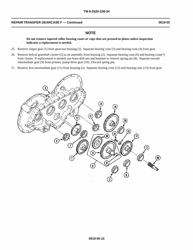
TM 9-2520-238-34
REPAIR TRANSFER GEARCASE F — Continued 0019 00
NOTE
Do not remove tapered roller bearing cones or cups that are pressed in plates unless inspectionindicates a replacement is needed.
25. Remove output gear (1) from gearcase housing (2). Separate bearing cone (3) and bearing cone (4) from gear.
26. Remove helical gearshaft cluster (5) as an assembly from housing (2). Separate bearing cone (6) and bearing cone(7)from cluster. If replacement is needed, use brass drift pin and hammer to remove spring pin (8). Separate secondintermediate gear (9) from primary pump-drive gear (10). Discard spring pin.
27. Remove first intermediate gear (11) from housing (2). Separate bearing cone (12) and bearing cone (13) from gear.
0019 00-10

TM 9-2520-238-34
REPAIR TRANSFER GEARCASE F — Continued 0019 00
28. Remove self-locking bolt (14), washer (15), and shouldered shaft (16) from gear (11). Discard bolt.
29. Remove secondary pump-drive gear (17) from housing (2).
30. Remove input gear (18) from housing (2). Separate bearing cone (19) and bearing cone (20) from gear.
31. As needed, remove bearing cup(s) from cover and housing (2) with mecchanical puller kit. Discard cup(s).
CLEANING
CLEAN, INSPECT AND REPAIR
1. Before inspection, repair or assembly, clean all parts (WP 0014 00).
CAUTION
Do not weld aluminum castings. If replacement of a bearing cup or cone is required, itsassociated cup or cone must be replaced. The housing and cover are machined as an unit andmust be replaced as an assembly.
2. Inspect all parts. Refer to (WP 0014 00) for general inspection and repair procedures. Check parts for wear limits andimportant clearances page 0019 00-25. Repair or replace defective parts as needed.
0019 00-11

TM 9-2520-238-34
REPAIR TRANSFER GEARCASE F — Continued 0019 00
ASSEMBLY
1. If bearing cup(s) were removed during disassembly, heat bearing bore to 250 degrees F 300 degrees F (121 degrees C-148 degrees C), and freeze bearing cup. Position bearing cup to its associated bearing bore. Use bearing cups replacerand soft plastic hammer to tap cup(s) in place.
NOTE
If roller bearing cone(s) were removed during disassembly, install new ones. New cone(s) maybe heated in oil 250 degrees F (121 degrees C) to aid in installation.
2. Place housing (1) flat on smooth surface with cover side up.
3. If removed, install bearing cone (2) and bearing cone (3) on input gear (4). Install gear in housing (1).
4. Install secondary pump-drive gear (5) in housing (1) with smaller diameter hub toward housing.
5. Install shouldered shaft (6) on first intermediate gear (7) with washer (8) and new self-locking bolt (9). Tighten bolt to32-38 lb-ft (44-51 N•m) torque. Use torque wrench (WP 0033 00, Item 44).
6. If removed, install bearing cone (10) and bearing cone (11) on first intermediate gear (7). Install gear in housing (1)meshing teeth with input gear (4).
0019 00-12

TM 9-2520-238-34
REPAIR TRANSFER GEARCASE F — Continued 0019 00
7. If dowel holes exist in second intermediate gear (1) and primary pump-drive gear (2), align holes in each gear. Securegears together with new spring pin (3). Stake pin three equal places at both ends.
8. If dowel holes do not exist in either second intermediate gear (1) or primary pump-drive gear (2), assemble gears anddrill a 0.375 to 0.380 inch diameter hole using a 3/8 inch drill bit. Use twist drill set and portable electric drill. Securesecond intermediate gear (1) and primary pump-drive gear (2) together with new spring pin (3). Stake pin three equalplaces at both ends.
9. If removed, install bearing cone (4) and bearing cone (5) on helical gearshaft cluster (6). Install helical gearshaft clusterin housing (7) meshing teeth of second intermediate gear (1) with first intermediate gear (8).
10. If removed, install bearing cone (9) and bearing cone (10) on output gear (11). Install output gear in housing (7) meshingteeth with second intermediate gear (1).
0019 00-13

TM 9-2520-238-34
REPAIR TRANSFER GEARCASE F — Continued 0019 00
CAUTION
Gearcase cover and housing are machined as a unit and must be replaced as a matched set.
11. If removed, install new alignment pin(s) (12) in housing (7). Tap in place using a soft plastic hammer.
12. Install new gasket (13) on housing (7). Align cover (14) with four pins (12) and place cover on housing.
13. Clean threads of cap screws (15) and machine screws (16). Apply a light coat of antiseize compound to screw threads.Secure cover (14) to housing (7) with 20 cap screws (15) on gearcase F, 20 new key washers (17), and 8 machine screws(16). Tighten screws to 144-192 lb-in (17-21 N.m) torque. Use torque wrench (WP 0033 00, Item 41). Bend tabs on keywashers.
0019 00-14

TM 9-2520-238-34
REPAIR TRANSFER GEARCASE F — Continued 0019 00
14. Lubricate new packing (1) with grease or petrolatum. Install packing and dust deflector (2) on shaft on disk assembly (3).
CAUTION
To prevent damage to encased oil seals, do not place housing in upright position until bearingretainers are installed.
To prevent damage to encased oil seals, do not press seals beyond face of bore. After installationseal must be flush with outer surface.
15. Clean encased oil seals. Apply a thin even film of sealing compound (WP 0035 00, Item 12) or (WP 0035 00, Item 13) tomating surface of seal (4) and seal (5). Position each seal with lip toward bore. Use a flat block of wood and soft plastichammer to tap seals in place.
16. Align splines of disk assembly (3) with splines of output gear and insert disk assembly shaft into output gear.
0019 00-15

TM 9-2520-238-34
REPAIR TRANSFER GEARCASE F — Continued 0019 00
17. Secure disk assembly (3) to output gear with gearcase washer assembly (6), new key washer (7), and cap screw (8).Tighten screw to 30-35 lb-ft (41-46 N.m) torque. Use torque wrench (WP 0033 00, Item 44). Bend tabs on key washer.
18. Insert engine disconnect actuator (9) through hole in top of housing (10). Secure housing bracket with washer (11) andnew cotter pin (12).
19. Insert ball bearing (13) into shift collar (14). Secure with new retaining ring (15).
20. Install shift collar (14) on input shouldered shaft (16). Secure with new retaining ring (17).
21. Align splines of input shaft (16) with input gear. Install input shaft with shift collar (14) aligned with actuator (9).
0019 00-16

TM 9-2520-238-34
REPAIR TRANSFER GEARCASE F — Continued 0019 00
22. If removed from gearcase F, install bearing cup(s) in retaining plate (18), retaining plate (19), retaining plate (20), orretaining plate (21) with bearing cups replacer and soft plastic hammer.
0019 00-17

TM 9-2520-238-34
REPAIR TRANSFER GEARCASE F — Continued 0019 00
23. Determine thickness of laminated shims (1), (2), (3), and (4) for bearing preload and install shims on cover (5) asdirected in Steps 24 - 30.
NOTE
Install output bearing retaining plate with oil hole up. Most retaining plates have the word TOPstamped in metal near oil hole.
24. Without new laminated shim (1) and four new key washers (6) installed, place output bearing retaining plate (7) on cover(5). Lube four cap screws (8) with engine oil and secure retaining plate (7) to cover with four screws. Tighten screwsuniformly to 168-192 lb-in (19-21 N.m). Use torque wrench (WP 0033 00, Item 41).
25. Rotate gear train one revolution by hand in each direction to check freedom of movement. Recheck installationprocedures if binding is detected.
NOTE
Ensure that the secondary pump-drive gear does not interfere with gear rotation. This gear isnonfunctional until the differential oil pump is installed.
26. Use a thickness gage to measure the gap between output bearing retaining plate (7) and cover (5) at three equal placesaround cover. Take the average of these readings and record. Peel shim (1) to 0.003-0.005 inch less than the averagerecorded in step above. Remove four cap screws (8) and retaining plate from cover.
0019 00-18

TM 9-2520-238-34
REPAIR TRANSFER GEARCASE F — Continued 0019 00
27. Repeat Steps 23 - 26 above using retaining plate (9), retaining plate (10), retaining plate (11), laminated shim (2),laminated shim (3), and laminated shim (4).
28. Lubricate new packing (12), packing (13), and packing (14) with grease or petrolatum. Install packings on retainingplate (7), retaining plate (9), and retaining plate (10).
29. Install retaining plate (7), retaining plate (9), and retaining plate (10) on cover (5). Apply a light coat of antiseizecompound to clean threads of cap screw (8), cap screw (15), and cap screw (16). Place laminated shims (1), (2), and (3)and retaining plate (7), retaining plate (9), and retaining plate (10) on cover. Secure plates with new key washer (6),new key washer (17), new key washer (18), and cap screw (8), cap screw (15), and cap screw (16). Tighten screws to252-300 lb-in (25-33 N•m) torque. Use torque wrench (WP 0033 00, Item 41). Bend tabs on key washers.
CAUTION
To prevent damage to encased oil seal, do not press seal beyond face of bore. After installationseal must be flush with outer surface.
30. Clean mating surface of new encased oil seal (19). Apply a thin film of sealing compound (WP 0035 00, Item 12) or(WP 0035 00, Item 13) to outer edge of oil seal. Install encased oil seal in first intermediate bearing retaining plate (10).
0019 00-19
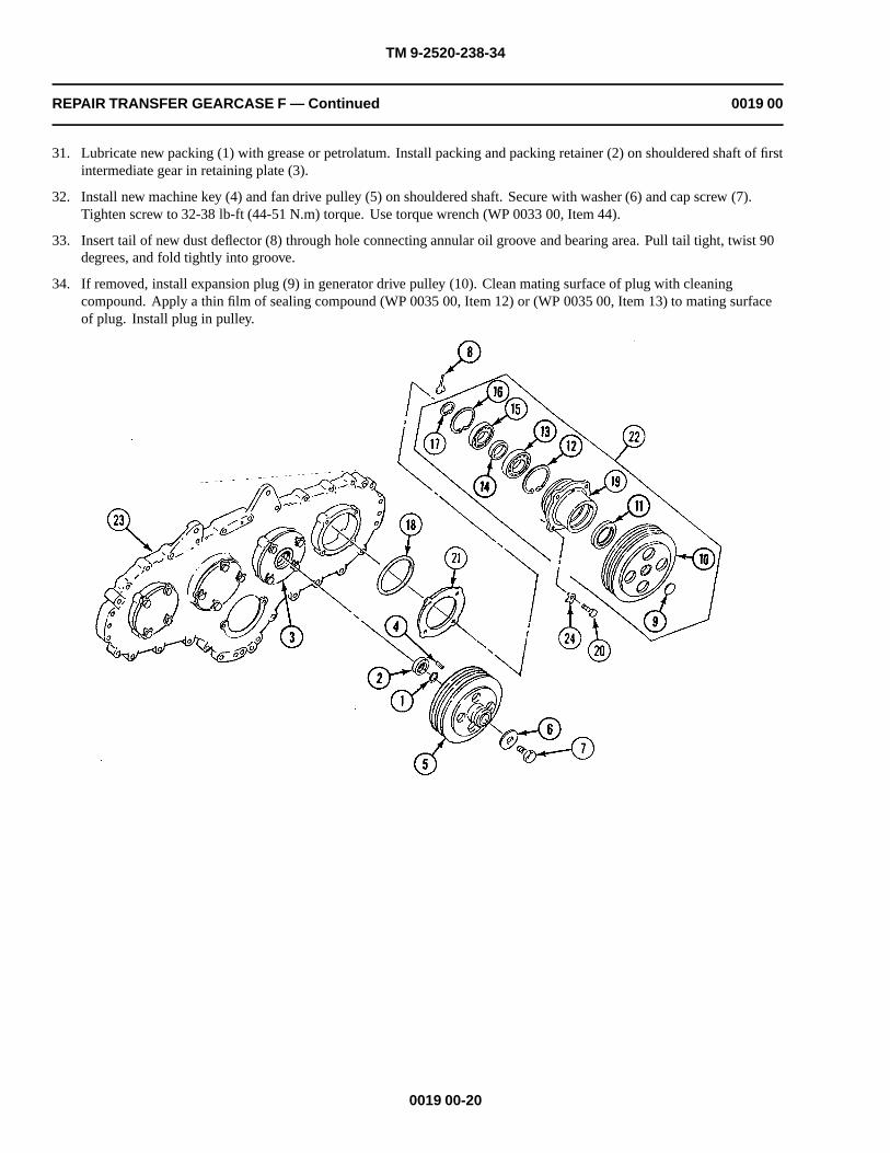
TM 9-2520-238-34
REPAIR TRANSFER GEARCASE F — Continued 0019 00
31. Lubricate new packing (1) with grease or petrolatum. Install packing and packing retainer (2) on shouldered shaft of firstintermediate gear in retaining plate (3).
32. Install new machine key (4) and fan drive pulley (5) on shouldered shaft. Secure with washer (6) and cap screw (7).Tighten screw to 32-38 lb-ft (44-51 N.m) torque. Use torque wrench (WP 0033 00, Item 44).
33. Insert tail of new dust deflector (8) through hole connecting annular oil groove and bearing area. Pull tail tight, twist 90degrees, and fold tightly into groove.
34. If removed, install expansion plug (9) in generator drive pulley (10). Clean mating surface of plug with cleaningcompound. Apply a thin film of sealing compound (WP 0035 00, Item 12) or (WP 0035 00, Item 13) to mating surfaceof plug. Install plug in pulley.
0019 00-20

TM 9-2520-238-34
REPAIR TRANSFER GEARCASE F — Continued 0019 00
CAUTION
To prevent damage to encased oil seal, do not press seal beyond face of bore. After installationseal must be flush with outer surface.
35. Clean mating surface of encased oil seal (11). Apply a thin film of sealing compound (WP 0035 00, Item 12) or(WP 0035 00, Item 13) to outer edge of oil seal. Install oil seal in retaining plate.
36. Install new retaining ring (12), ball bearing (13), sleeve spacer (14), ball bearing (15), and new retaining ring (16) onpulley (10). Secure with new retaining ring (17).
37. Lubricate new packing (18) with grease or petrolatum. Install packing on retaining plate (19).
38. Apply a light coat of antiseize compound to clean threads of four cap screws (20). Install laminated shim (21) and generator drive assembly (22) on cover (23) with four new key washers (24) and cap screws (20). Tighten screws to252-300 lb-in (25-33 N.m) torque. Use torque wrench (WP 0033 00, Item 41). Bend tabs on key washers.
0019 00-21

TM 9-2520-238-34
REPAIR TRANSFER GEARCASE F — Continued 0019 00
39. Install resilient mount (1) in housing (2). Use remover and replacer. Install cover (3) on housing with two newlockwashers (4) and cap screws (5).
40. Install new retaining ring (6) on pump (7). Install new machine key (8) in shaft of pump. Apply a light coat of antiseizecompound to clean threads of two cap screws (9). Place new gasket (10) on housing (2). Secure pump to secondarypump-drive gear with two (maximum) washers (12), slotted head nut (13), and new cotter pin (14).
41. Install pump in housing (2) with two new key washers (15) and cap screws (9). Tighten screws to 35-40 lb-ft (47-54N.m) torque. Use torque wrench (WP 0033 00, Item 44).
42. Install actuating coupling (16) on housing (2) with new headless grooved pin (17).
43. Apply a light coat of antiseize compound to clean threads of four cap screws (18). Install new gasket (19) and sleevespacer (20) in bracket (21) with four cap screws. Secure screws with new lockwire (22).
0019 00-22
This is an internal gear and is notremoved here. This is only shown
as a reference for the pump installation.
NOTE
44. Lubricate new packing (23) with grease or petrolatum. Install packing on bracket (21). Apply a light coat of antiseizecompound to clean threads of two cap screws (24). Install bracket in cover (3) with two key washers (25) and cap screws.Tighten screws to 168-192 lb-in (19-21 N.m). Use torque wrench (WP 0033 00, Item 41). Bend tabs on key washers.
45. Lubricate new packing (26) with grease or petrolatum. Install packing and breather (27) on straight adapter (28). Installadapter in housing (2).
46. Install eye bolt (29) in housing (2).
47. Apply sealing compound around side of plug (33). Install plug and drive screw (32).

TM 9-2520-238-34
REPAIR TRANSFER GEARCASE F — Continued 0019 00
48. Lubricate new packing (30) with grease. Install packing on drain plug (31). Install plug in housing (2).
0019 00-23
N
Take care to prevent damage to machined surfaces, gears, bearings, and other componentsduring maintenance activities.
O
WARNING
ITUA
Lifting or moving objects in excess of 70 pounds could injure you. Make sure to get an assistantor use a lifting device to move heavy objects.
C
49. Lift transfer gearcase using suitable lifting device and sling through eye bolt (29). Place gearcase on test stand for run-in test.
This is an internal gear and is notremoved here. This is only shown
as a reference for the pump installation.
NOTE

TM 9-2520-238-34
REPAIR TRANSFER GEARCASE F — Continued 0019 00
RUN-IN TEST
NOTE
Conduct run-in test in accordance with local standard procedures.
1. Mount gearcase on test stand in the same position as when installed in the carrier.
2. Fill gearcase with 5 pints of oil (WP 0014 00). Oil level is to be between the ADD and FULL marks on liquid levelgauge rod.
3. Provide suitable external lubricating oil supply for the differential oil pump and the ramp hydraulic pump (if installed).
4. Before run-in operation. Provide artificial heating and cooling, if needed.
NOTE
Do not allow oil temperature to exceed 280 degrees F (138 degrees C) at any time during run-intests. At each stage, watch for over-heating, undue noise, and vibration. Check all seals andcovers for oil leakage.
5. Run gearcase in the following minimum time duration stages.
Table 1.
Stage (rpm) Load (foot-pounds) Stage Time (minutes)
1100 to 1300 No load 5
1900 to 2100 No load 5
2800 to 3000 No load 5
6. Remove drain plug and drain oil for at least 15 minutes into a suitable container and then install drain plug.
7. Leave oil residue in gearcase for rust prevention.
0019 00-24
8. Remove sling and lifting device from transfer gearcase.

TM 9-2520-238-34
REPAIR TRANSFER GEARCASE F — Continued 0019 00
WEAR LIMITS
1. See TM 9-214 to check bearings.
2. Check parts that have reference letters in figures.
0019 00-25

TM 9-2520-238-34
REPAIR TRANSFER GEARCASE F — Continued 0019 00
3. Check the parts dimensions with chart below to determine replacement.
Table 2. TRANSFER GEARCASE F WEAR LIMITS
ReferenceLetter
Point of Measurement Size and Fit of New Parts Wear Limits
AOutside diameter of first and second intermediatebearing cup
3.5425 to 3.5435(*)(***)
B Outside diameter of output bearing cup 3.5425 to 3.5435 (*)(***)
C Fan drive pulley shaft 1.0000 to 1.0010 (*)(**)
DInside diameter of bore in first intermediate retainer atbearing surface
3.5410 to 3.5420(*)(***)
E Inside diameter of fan pulley hub 1.0000 to 1.0020 (*)(**)
E-C Fit of fan pulley hub on shaft 0.0010T to 0.0020L (*)
FInside diameter of bore in second intermediate retainerat bearing surface
3.5410 to 3.5420(*)(***)
F-AFit of first and second intermediate bearing cup toretainer bores
0.0005T to 0.0025T(*)
G Inside diameter of bore in output retainer 3.3449 to 3.3459 (*)(***)
G-B Fit of output bearing cup to retainer bore 0.0005T to 0.0025T (*)
* Must be within new parts dimensions.
** Measure only if there are visual signs of wear or damage.
*** Measure only if there is visual indication of bearing turning.
END OF TASK
0019 00-26

TM 9-2520-238-34
CHAPTER 6
DIRECT SUPPORT MAINTENANCE INSTRUCTIONSFOR REPAIR FINAL DRIVE ASSEMBLIES
WORK PACKAGE INDEX
Title Sequence No.
REPAIR FINAL DRIVE ASSEMBLIES A AND B..........................................................................................................0020 00


TM 9-2520-238-34
REPAIR FINAL DRIVE ASSEMBLIES A AND B 0020 00
THIS WORK PACKAGE COVERS:
Disassembly (page 0020 00-2).Cleaning (page 0020 00-6).Assembly (page 0020 00-7).Run-in Test (page 0020 00-13).Wear Limits (page 0020 00-14).
INITIAL SETUP:
Maintenance Level
Direct Support
Tools and Special Tools
General mechanic’s tool kit (WP 0033 00, Item 37)Arbor press (WP 0033 00, Item 16)Jack screw (2) (WP 0033 00, Item 30)Puller kit (WP 0033 00, Item 17)Remover/Replacer (WP 0033 00, Item 25)Straight pin (WP 0033 00, Item 14)Torque wrench (WP 0033 00, Item 41)Torque wrench (WP 0033 00, Item 44)Vernier height gage (WP 0033 00, Item 8)
Materials/Parts
Antiseize compound (WP 0035 00, Item 1)Engine lubricating oil (WP 0035 00, Item 5)Grease automotive (WP 0035 00, Item 6)Petrolatum (WP 0035 00, Item 10)Sealing compound (WP 0035 00, Item 12)Sealing compound (WP 0035 00, Item 13)Sealing compound (WP 0035 00, Item 14)Sealing compound (WP 0035 00, Item 16)Wiping rag (WP 0035 00, Item 17)GasketGasketGasketGasketGasketKey washerKey washer (4)Key washer (6)Key washer (8)Preformed packingSealSealSelf-locking bolt (3)Self-locking bolt (4)Self-locking bolt (14)
Personnel Required
Track Vehicle Repairer
References
See your -10See your -20TM 9-214
Equipment Condition
Final drive removed from carrier (see your -20)
0020 00-1
Sling (WP 0033 00, Item 32)

TM 9-2520-238-34
REPAIR FINAL DRIVE ASSEMBLIES A AND B — Continued 0020 00
DISASSEMBLY
CAUTION
Take care to prevent damage to machined surfaces, gears, bearings, and other componentsduring disassembly, cleaning, inspection, and assembly.
1. Remove four lock bolts (1), three lock bolts (2), seven washers (3), seal retaining cover (4), and gasket (5) from housingcover (6). Discard lock bolts and gasket.
2. Remove metal ring oil seal (7) from cover (4). Discard seal.
3. Straighten tabs on four key washers (8). Remove four cap screws (9), key washers (8), access cover (10), and gasket (11)from bearing retaining plate (12). Discard key washers and gasket.
4. Straighten tabs on six key washers (13). Remove six cap screws (14), key washers (13), bearing retaining plate (12), andgasket (15) from housing cover (6). Discard key washers and gasket.
0020 00-2

TM 9-2520-238-34
REPAIR FINAL DRIVE ASSEMBLIES A AND B — Continued 0020 00
5. Remove 14 lock bolts (1) and washers (2) holding housing cover (3) to housing (4). Install two jack screws evenly intojacking screw holes in housing cover (3) and remove cover and gasket (5). Discard gasket and lock bolts.
6. Remove spur gear (6) with two attached inner races (7) from housing (4).
7. Remove spur gear (8) with two attached inner races (9) from housing (4).
8. Remove packing (10) from gear (8). Discard packing.
0020 00-3

TM 9-2520-238-34
REPAIR FINAL DRIVE ASSEMBLIES A AND B — Continued 0020 00
NOTE
Both inner race and outer race of roller bearings are matched sets and must be replaced ifeither is defective.
9. If inspection indicates that inner race (7) or inner race (9) or outer race (11) or outer race (12) requires replacement,remove applicable outer race(s) from bore(s) of housing cover (3) or from bore(s) of housing (4). Remove applicableinner race(s) from spur gear (6) or spur gear (8). Discard both outer race(s) and inner race(s).
10. Remove retaining ring (13) from housing (4).
0020 00-4
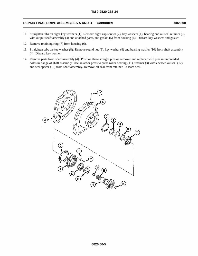
TM 9-2520-238-34
REPAIR FINAL DRIVE ASSEMBLIES A AND B — Continued 0020 00
11. Straighten tabs on eight key washers (1). Remove eight cap screws (2), key washers (1), bearing and oil seal retainer (3)with output shaft assembly (4) and attached parts, and gasket (5) from housing (6). Discard key washers and gasket.
12. Remove retaining ring (7) from housing (6).
13. Straighten tabs on key washer (8). Remove round nut (9), key washer (8) and bearing washer (10) from shaft assembly(4). Discard key washer.
14. Remove parts from shaft assembly (4). Position three straight pins on remover and replacer with pins in unthreadedholes in flange of shaft assembly. Use an arbor press to press roller bearing (11), retainer (3) with encased oil seal (12),and seal spacer (13) from shaft assembly. Remove oil seal from retainer. Discard seal.
0020 00-5
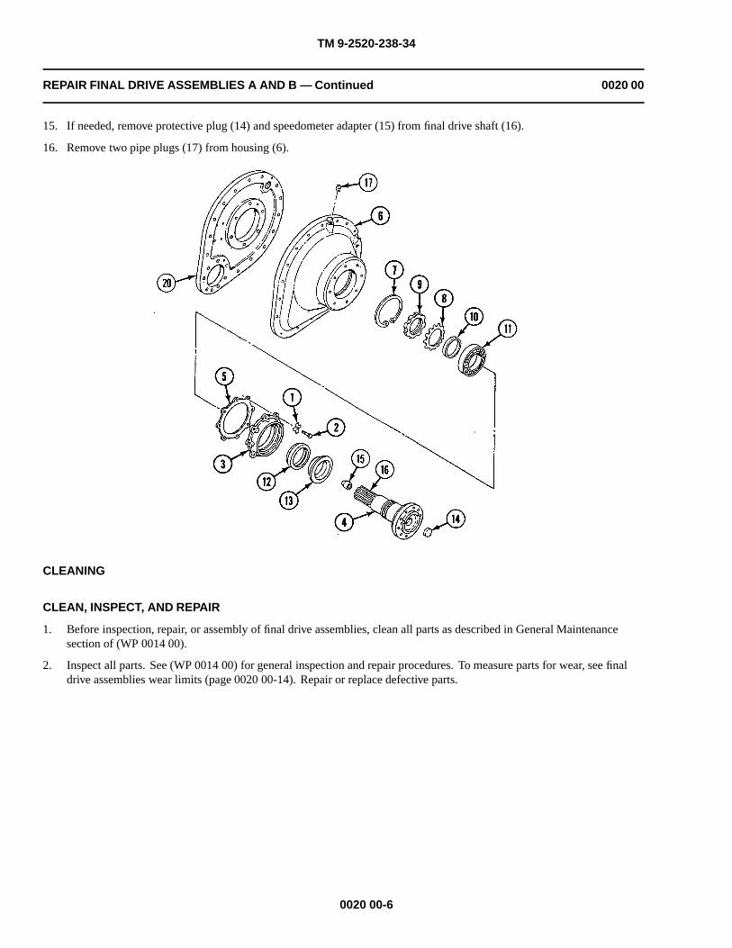
TM 9-2520-238-34
REPAIR FINAL DRIVE ASSEMBLIES A AND B — Continued 0020 00
15. If needed, remove protective plug (14) and speedometer adapter (15) from final drive shaft (16).
16. Remove two pipe plugs (17) from housing (6).
CLEANING
CLEAN, INSPECT, AND REPAIR
1. Before inspection, repair, or assembly of final drive assemblies, clean all parts as described in General Maintenancesection of (WP 0014 00).
2. Inspect all parts. See (WP 0014 00) for general inspection and repair procedures. To measure parts for wear, see finaldrive assemblies wear limits (page 0020 00-14). Repair or replace defective parts.
0020 00-6

TM 9-2520-238-34
REPAIR FINAL DRIVE ASSEMBLIES A AND B — Continued 0020 00
ASSEMBLY
NOTE
The final drive housing and cover are machined as a unit and must be retained or replaced as amatched set.
1. Apply sealing compound (WP 0035 00, Item 14) to small end of pipe threads. Do not apply sealant beyond small end ofpipe threads. Do not fill leading thread. Install two pipe plugs (1) in housing (2).
2. If removed during disassembly, install new speedometer adapter (3) and protective plug (4) in final drive shaft (5).
3. Position shaft assembly on level surface on arbor press with splined end up. On chamfered surface of seal spacer (6)nearest output shaft assembly (7), apply a coat of sealing compound (WP 0035 00, Item 16). Place spacer (6) on shaftassembly so spacer holes are between the 3/8 inch diameter holes in shaft assembly. Using a metal tube with samediameter as spacer (6) and arbor press, press spacer on output shaft assembly.
0020 00-7

TM 9-2520-238-34
REPAIR FINAL DRIVE ASSEMBLIES A AND B — Continued 0020 00
CAUTION
To prevent damage to encased oil seal, do not press seal beyond face of bore. After installationseal must flush with outer surface. Keep replacer clear of three steel pins in oil seal.
4. Install new encased oil seal (8) in bearing and oil seal retainer (9). Clean mating surface of oil seal. Apply a thin film ofsealing compound (WP 0035 00, Item 12) or (WP 0035 00, Item 13) to outer edge of oil seal. Use remover/replacer andhammer.
5. Install retainer (9) on shaft assembly (7) with three gasket steel pins of seal (8) in three holes in retainer.
6. Press roller bearing (10) on shaft assembly (7) so that inner race fits tightly against spacer (6). Secure with bearingwasher (11), new key washer (12), and round nut (13) with chamfered side toward washer. Bend tabs on key washer. Usearbor press and remover/replacer.
7. Install retaining ring (14) in housing (2).
8. Install retainer (9) with attached parts on housing (2).
0020 00-8

TM 9-2520-238-34
REPAIR FINAL DRIVE ASSEMBLIES A AND B — Continued 0020 00
9. Apply a light coat of antiseize compound to clean threads of eight cap screws (1). Place new gasket (2) and retainer (3)on housing (4). Secure with eight new key washers (5) and cap screws (1). Torque screws to 264-288 lb-in (30-32 N•m).Use torque wrench (WP 0033 00, Item 41). Bend tabs on key washers.
NOTEBoth inner race and outer race of roller bearings are matched sets and must be replaced ifeither is defective.
10. If removed during disassembly, press new outer race (6) or outer race (7) in bore(s) in housing cover (8). Press applicablenew inner race (9) or inner race (10) on hub(s) of spur gear (11) or spur gear (12). Use arbor press and remover/replacer.
0020 00-9

TM 9-2520-238-34
REPAIR FINAL DRIVE ASSEMBLIES A AND B — Continued 0020 00
11. Install retaining ring (13) in housing (4).
12. If removed during disassembly, press new outer race (6) or new outer race (7) in bore(s) in housing (4). Press applicablenew inner race (9) or new inner race (10) on hub(s) of spur gear (11) or spur gear (12). Use arbor press and remover/replacer.
13. Lubricate new packing (14) with grease or petrolatum and install packing in spur gear (11).
0020 00-10

TM 9-2520-238-34
REPAIR FINAL DRIVE ASSEMBLIES A AND B — Continued 0020 00
14. Install spur gear (1) in housing (2).
15. Install spur gear (3) in housing (2).
16. Install new gasket (4) and housing cover (5) on housing (2) with 14 washers (6) and new lock bolts (7). Torque bolts to34-36 lb-ft (46-49 N.m). Use torque wrench (WP 0033 00, Item 44).
17. Apply a light cost of antiseize compound to clean threads of six cap screws (8). Place new gasket (9) and retaining plate(10) on cover (5). Secure with six new key washers (11) and cap screws (8). Torque screws to 264-288 lb-in (30-33N.m). Use torque wrench (WP 0033 00, Item 41). Bend tabs on key washers.
0020 00-11

TM 9-2520-238-34
REPAIR FINAL DRIVE ASSEMBLIES A AND B — Continued 0020 00
NOTE
Do not bend two lower key washers that mount loop clamps for final drive left or right fillertube and liquid gage rod installed in Step 20.
18. Apply a light coat of antiseize compound to clean threads of four cap screws (12). Place new gasket (13) and accesscover (14) on retaining plate (10). Secure with four new key washers (15) and cap screws (12). Bend tabs on two upperkey washers.
CAUTION
To prevent damage to metal ring oil seal, do not press seal beyond face of bore. Afterinstallation seal must be flush with outer surface.
19. Clean mating surface of oil seal. Apply a thin film of sealing compound (WP 0035 00, Item 12) or (WP 0035 00, Item13) to outer edge of oil seal. Install oil seal (16) in retaining cover (17) with sealing lip in towards bearing.
NOTE
Install three longer lock bolts (20) in bottom holes in housing cover (5).
20. Install new gasket (18) and retaining cover (17) on housing cover (5) with seven washers (19), three new lock bolts (20),and four new lock bolts (21). Torque bolts to 34-36 lb-ft (46-49 N•m). Use torque wrench (WP 0033 00, Item 44).
0020 00-12

TM 9-2520-238-34
REPAIR FINAL DRIVE ASSEMBLIES A AND B — Continued 0020 00
RUN-IN TEST
NOTE
Conduct run-in test in accordance with local operating procedures.
2. Mount final drive in same position as in the carrier (line connecting input and output shaft center lines at 15 to 25 degreesfrom vertical).
3. Install filler tube, liquid level gage rod, vent tube and elbow, and adapter as installed in carrier (see your -20).
4. Fill housing with oil between ADD and FULL marks on liquid level gage rod (about 3-1/2 quarts or 7 pints).
5. Operate final drive according to the following schedule, checking for undue noise level, local heating, leaks, andvibration at each phase:
Table 1. RUN-IN TEST SCHEDULE
Stage (rpm) Direction Stage Time (minutes)
900 to 1100 Forward 6 to 8
900 to 1100 Reverse 6 to 8
1900 to 2100 Forward 3 to 5
1900 to 2100 Reverse 3 to 5
2900 to 3100 Forward 1 to 3
2900 to 3100 Reverse 1 to 3
6. Drain oil into a suitable container. Leave residual oil for use as a preservative during shipping and storage.
7. Remove filler tube and vent components installed in Step 2 above (see your -20).
8. Cover filler tube vent and input shaft openings.
0020 00-13
Take care to prevent damage to machined surfaces, gears, bearings, and other componentsduring maintenance activities.
NO
WARNING
ITUA
Lifting or moving objects in excess of 70 pounds could injure you. Make sure to get an assistantor use a lifting device to move heavy objects.
C
1. Install sling and suitable lifting device to final drive
9. Remove sling and suitable lifting device from final drive

TM 9-2520-238-34
REPAIR FINAL DRIVE ASSEMBLIES A AND B — Continued 0020 00
WEAR LIMITS
1. See TM 9-214 to check bearings.
2. Check parts that have reference letters in figures.
3. Check the parts dimensions with chart on next page to determine replacement.
0020 00-14

TM 9-2520-238-34
REPAIR FINAL DRIVE ASSEMBLIES A AND B — Continued 0020 00
Table 2. FINAL DRIVE A AND B WEAR LIMITS
ReferenceLetter
Point of MeasurementSize and Fit of New
PartsWear Limits
A Inside diameter of spur gear bearing bore in cover 5.5112 to 5.5128 (***) 5.5132
B Outside diameter of spur gear bearing 5.5110 to 5.5118 (*)(***)
B-A Fit of bearing in cover bore 0.0006T to 0.0018L
C Inside diameter of spur gear bearing 3.1490 to 3.1496 (*)(***)
D Outside diameter of spur gear hub bearing surface 3.1504 to 3.1511 (*)(***)
D-C Fit of bearing to spur gear hub 0.0008T to 0.0021T
E Inside diameter of spur gear bearing bore in housing 5.5112 to 5.5128 5.5132
E-B Fit of bearing in housing bore 0.0006T to 0.0018T
F Inside diameter of gear bearing bore in housing 3.9370 to 3.9380 3.9384
G Outside diameter of gear bearing 3.9364 to 3.9370 (*)(***)
G-F Fit of bearing in housing bore 0.0000 to 0.0016L
H Inside diameter of gear bearing 2.1648 to 2.1654 (*)(***)
I Outside diameter at gear bearing surface of gear hub 2.1230 to 2.1270 (*)(***)
I-H Fit of bearing on gear 0.0008T to 0.0021T
J Outside diameter at seal surface of gear hub 2.1662 to 2.1670 (**) 2.1210
K Inside diameter of gear bearing bore in cover 3.9370 to 3.9380 (***) 3.9384
K-G Fit of bearing in cover bore 0.0000 to 0.0016T
L Inside diameter of housing output bearing bore 5.5112 to 5.5128 (***) 5.5132
M Outside diameter of output bearing 5.5110 to 5.5118 (*)(***)
M-L Fit of bearing in housing bore 0.0006T to 0.0028L
N Inside diameter of output bearing 3.1490 to 3.1496 (*)(***)
O Outside diameter at output bearing surface of output shaft 3.1504 to 3.1511 (*)(***)
O-N Fit of bearing on output shaft 0.0008T to 0.0021T
* Must be within new parts dimensions.
** Measure only if there is visual indication of bearing turning.
*** Measure only if there is visual indication of wear or damage.
END OF TASK
0020 00-15/16 blank


TM 9-2520-238-34
CHAPTER 7
DIRECT/GENERAL SUPPORT MAINTENANCE INSTRUCTIONSFOR STEERING CONTROL DIFFERENTIAL
WORK PACKAGE INDEX
Title Sequence No.
REPLACE STRAIGHT ADAPTER AND BRAKE SHOE ASSEMBLIES.....................................................................0021 00
REPAIR BRAKE SHOE ASSEMBLIES...........................................................................................................................0022 00
REPLACE OUTPUT SHAFT ASSEMBLIES..................................................................................................................0023 00
REPAIR OUTPUT SHAFT ASSEMBLIES......................................................................................................................0024 00
REPLACE DIFFERENTIAL STEERING CONTROL ASSEMBLY...............................................................................0025 00
REPAIR DIFFERENTIAL STEERING CONTROL ASSEMBLY...................................................................................0026 00
REPLACE DIFFERENTIAL RIGHT ANGLE GEARBOX.............................................................................................0027 00
REPAIR DIFFERENTIAL RIGHT ANGLE GEARBOX.................................................................................................0028 00
REPAIR STEERING CONTROL DIFFERENTIAL HOUSING......................................................................................0029 00
DIRECT SUPPORT
GENERAL SUPPORT


TM 9-2520-238-34
REPLACE STRAIGHT ADAPTER AND BRAKE SHOE ASSEMBLIES 0021 00
THIS WORK PACKAGE COVERS:
Removal (page 0021 00-2).Cleaning (page 0021 00-4).Installation (page 0021 00-5).
INITIAL SETUP:
Maintenance Level
Direct Support
Tools and Special Tools
General mechanic’s tool kit (WP 0033 00, Item 37)Torque wrench (WP 0033 00, Item 41)Socket wrench set (WP 0033 00, Item 34)
Materials/Parts
Antiseize compound (WP 0035 00, Item 1)Cleaning compound (WP 0035 00, Item 4)Sealing compound (WP 0035 00, Item 15)Wiping rags (WP 0035 00, Item 17)GasketGasketKey washers (4)Key washers (13)Self-locking nut (3)
Personnel Required
Track Vehicle Repairer
References
See your -20See your PMCS
Equipment Condition
Steering control differential removed from carrier (seeyour -20)
0021 00-1

TM 9-2520-238-34
REPLACE STRAIGHT ADAPTER AND BRAKE SHOE ASSEMBLIES — Continued 0021 00
REMOVAL
CAUTION
Take care during handling and disassembly to protect machined surfaces, gears, bearings, andcomponents from damage. Provide safe blockage arrangement.
1. Drain differential oil into suitable container (see your PMCS).
2. Remove dipstick (1) and breather (2) from differential (3).
3. Remove locknut (4), screw (5), clamp (6), and clamp (7). Separate differential oil hose (8) from circuit 328 lead (9).Discard locknut.
4. Remove screw (10), washer (11), clamp (12) and oil hose (8) from differential gearbox (13).
5. Disconnect oil hose (8) from elbow (14) and elbow (15).
6. Remove elbow (15) from adapter (16).
7. Remove elbow (14) from differential gearbox (13).
0021 00-2
Parts of the brake assembly may be coated with asbestos dust. Breathing this dust can harmpersonnel. Use a filter mask approved for use against asbestos dust. Never use compressed airor dry brush to clean these assemblies. Use an industrial type vacuum cleaner with ahigh-efficiency filter system to remove dust. Use water and a soft bristle brush or cloth toremove dirt or mud.
WARNING

TM 9-2520-238-34
REPLACE STRAIGHT ADAPTER AND BRAKE SHOE ASSEMBLIES — Continued 0021 00
8. Remove two locknuts (1), screws (2), and two brake levers (3) from differential brake lever shafts. Discard locknuts.
9. Straighten tabs on 13 key washers (4). Remove 13 cap screws (5), key washers, housing cover (6) and gasket (7) fromdifferential gearbox (8). Discard key washers and gasket.
0021 00-3

TM 9-2520-238-34
REPLACE STRAIGHT ADAPTER AND BRAKE SHOE ASSEMBLIES — Continued 0021 00
10. Disconnect two nonmetallic hoses (1) from straight adapters (2).
11. Straighten tabs on four key washers (3). Remove four cap screws (4), key washers, adapter (5), and gasket (6) fromdifferential housing (7). Discard key washers and gasket.
12. Remove two adapters (2) from adapter (5).
13. Remove brake access plug (8) from differential housing (7).
NOTE
Procedures are the same for left and right brake shoe assemblies.
14. Remove brake shoe assemblies as follows. Remove steering brake adjusting nut (9) securing rod end and clevis (10) topin (11) in steering brake shaft (12). Remove pin (11) from brake shaft (12). Separate washer (13) and helical spring (14) from clevis (10). Remove brake shoe assembly (15) from differential housing (7). Install helical spring (14) and washer (13) on clevis (10). Install pin (11) in brake shaft (12). Install clevis (10) in pin (11). Secure clevis (10) with adjusting nut (9) until repair of brake shoe assembly is complete. Use socket wrench set.
CLEANING
CLEAN, INSPECT, AND REPLACE
1. Refer to (WP 0014 00) for inspection before and after disassembly and for cleaning during maintenance and afterdisassembly. Visually inspect gears, brake linings, hoses, and linkages for excessive wear and damage duringdisassembly.
0021 00-4

TM 9-2520-238-34
REPLACE STRAIGHT ADAPTER AND BRAKE SHOE ASSEMBLIES — Continued 0021 00
INSTALLATION
NOTE
Procedures are the same for left and right brake shoe assemblies.
Make sure hose and elbow are positioned properly on brake shoe when it is installed indifferential housing.
1. Install two brake shoe assemblies (1) in differential housing (2). Remove steering brake adjusting nut (3), rod end clevis(4), washer (5), and helical spring (6) from brake shoe assembly. Position brake shoe assembly (1) around brake drum(17), and install pin (7) through steering brake shaft (8). Install spring and washer over clevis. Insert clevis through pinand secure with adjusting nut (3). Repeat steps above for other brake shoe assembly.
2. Install brake access plug (9) in differential housing (2) as follows. Apply a light coat of antiseize compound to cleanthreads of plugs. Install plugs in housing.
3. Install pipe to tube elbow (10) and two adapters (11) in adapter (12). Clean male tapered pipe threads thoroughly. Applysealing compound to small end of pipe threads. Do not fill leading thread. Install elbow at a 30� angle from thehorizontal toward base of adapter.
4. Install adapter (12) on differential housing (2). Clean threads of cap screws (13) thoroughly. Apply a light coat ofantiseize compound to threads at installation. Place new gasket (14) on housing. Connect two nonmetallic hoses (15) toadapters. Place adapter on housing (2). Secure with four new key washers (16) and screws (13). Tighten screws to252-300 lb-in (29-34 N•m) torque. Use torque wrench and socket set. Bend tabs on key washers.
0021 00-5
17

TM 9-2520-238-34
REPLACE STRAIGHT ADAPTER AND BRAKE SHOE ASSEMBLIES — Continued 0021 00
5. Install housing cover (1) on differential housing (2) as follows. Apply a light coat of antiseize compound to clean threadsof 13 cap screws (3). Place new gasket (4) and housing cover on housing. Secure with 13 new key washers (5) and capscrews. Tighten screws to 252-300 lb-in (29-34 N•m) torque. Use torque wrench and socket set. Bend tabs on key
6. Install two levers (6) on differential brake shafts. Secure with two screws (7) and new locknuts (8).
7. Tighten locknuts (8) to 360-420 lb-in (41-47 N•m) torque. Use torque wrench.
0021 00-6
washers.

TM 9-2520-238-34
REPLACE STRAIGHT ADAPTER AND BRAKE SHOE ASSEMBLIES — Continued 0021 00
8. Apply a thin even coat of sealing compound to cleaned external threads of elbow (1) and elbow (2).
9. Install elbow (2) in differential gearbox (3).
10. Connect differential oil hose (4) to elbow (1) and elbow (2).
11. Apply antiseize compound to external threads of screw (5).
12. Install oil hose (6) on differential gear box (3) with clamp (7) and washer (8). Secure with screw (5). Tighten screw (5)to 252-300 lb-in (28-34 N•m) torque. Use torque wrench.
13. Install circuit 328 lead (9) and oil hose (6) together with clamp (10), clamp (11), and secure with screw (12) and newlocknut (13).
14. Fill differential oil (see your PMCS).
15. Install breather (14) and dipstick (15) on differential (16).
END OF TASK
0021 00-7/8 blank


TM 9-2520-238-34
REPAIR BRAKE SHOE ASSEMBLIES 0022 00
THIS WORK PACKAGE COVERS:
Disassembly (page 0022 00-2).Cleaning (page 0022 00-4).Assembly (page 0022 00-5).Wear Limits (page 0022 00-8).
INITIAL SETUP:
Maintenance Level
Direct Support
Tools and Special Tools
General mechanic’s tool kit (WP 0033 00, Item 37)Brake and clutch reliner (WP 0033 00, Item 19)Portable electric drill, 1/2 inch (WP 0033 00, Item 4)Twist drill set (WP 0033 00, Item 6)Vernier height gage (WP 0033 00, Item 8)
Materials/Parts
Cleaning compound (WP 0035 00, Item 4)Sealing compound (WP 0035 00, Item 14)Cotter pin (2)Cotter pin (6)RivetStraight pin (3)Straight pin
Personnel Required
Track Vehicle Repairer
References
TM 9-214
Equipment Condition
Brake shoe assembly removed (WP 0021 00)
0022 00-1

TM 9-2520-238-34
REPAIR BRAKE SHOE ASSEMBLIES — Continued 0022 00
DISASSEMBLY
WARNING
Parts of the brake assembly may be coated with asbestos dust. Breathing this dust can harmpersonnel. Use a filter mask approved for use against asbestos dust. Never use compressed airor dry brush to clean these assemblies. Use an industrial type vacuum cleaner with ahigh-efficiency filter system to remove dust. Use water and a soft bristle brush or cloth toremove dirt or mud.
CAUTION
Take care during handling and disassembly to protect machined surfaces, gears, bearings, andcomponents from damage. Provide safe blockage arrangement and place differential intosubassemblies.
NOTEAll brake shoe assemblies are disassembled the same way.
Remember position of pipe to tube elbow (1) for proper installation later.
1. Remove hose (2), pipe to tube elbow (1), and pipe plug (3) from brake shoe (4).
0022 00-2

TM 9-2520-238-34
REPAIR BRAKE SHOE ASSEMBLIES — Continued 0022 00
2. Remove steering brake adjusting nut (1) from rod end clevis (2). Remove clevis and pin (3) from steering brake shaft (4).Remove washer (5) and helical spring (6) from clevis (2).
3. Remove solid rivet (7) and pin (8) holding steering brake shaft (4) to link (9). Separate pin and brake shaft from link.Discard rivet.
4. Remove six cotter pins (10) and three straight headless pins (11). Separate brake shoe (12), brake shoe (13), and brakeshoe (14). Discard cotter pins and straight pins.
5. Remove two cotter pins (15) and straight headless pin (16). Separate rod end clevis (2) from shoe (14). Discard cotterpins and straight pin.
NOTE
If inspection indicates brake friction linings must be replaced, do (page 0022 00-8).
6. Remove 12 tubular rivets (17) from each friction lining (18) on brake shoe (12), brake shoe (13), and brake shoe (14).Discard friction linings and rivets. Use drill and twist drill set.
0022 00-3
TM 9-2520-238-34
REPAIR BRAKE SHOE ASSEMBLIES — Continued 0022 00
CLEANING
CLEAN, INSPECT, AND REPAIR
1. Before inspection, repair, or assembly, clean all parts of each output shaft assembly as described in (WP 0014 00).
2. Inspect all parts. Refer to (WP 0014 00) for general inspection and repair procedures. Check wear limits and clearancesof parts (page 0022 00-8). Repair or replace defective parts.
3. Measure springs for free (no tension or compression) length of 3-3/8 to 3-5/8 inches (8.6 to 9.2 cm). Replace any springsnot within these dimensions.
0022 00-4

TM 9-2520-238-34
REPAIR BRAKE SHOE ASSEMBLIES — Continued 0022 00
ASSEMBLY
NOTE
All brake shoe assemblies are assembled the same way.
If brake friction linings were removed in (page 0022 00-2), do Step 3.
Friction linings must be riveted tightly against the shoe so that a 0.020 inch (0.51 mm) shimcannot be inserted beyond the lengthwise centerline of rivets.
Check the color code (stripes) on the side of all three friction linings. All three brake liningsmust have the same number and color of stripes when installed. Do not mix different types ofbrake linings.
Install a complete new set of three linings each time any lining is changed.
1. Place three new friction linings (1) on shoe (2), shoe (3), and shoe (4). Secure each lining to its respective shoe with 12new tubular rivets (5). Use brake and clutch reliner.
0022 00-5
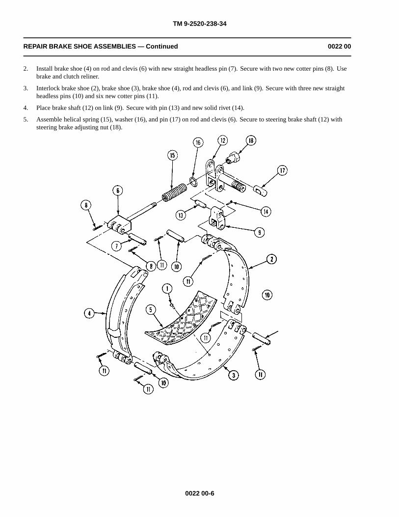
TM 9-2520-238-34
REPAIR BRAKE SHOE ASSEMBLIES — Continued 0022 00
2. Install brake shoe (4) on rod and clevis (6) with new straight headless pin (7). Secure with two new cotter pins (8). Usebrake and clutch reliner.
3. Interlock brake shoe (2), brake shoe (3), brake shoe (4), rod and clevis (6), and link (9). Secure with three new straightheadless pins (10) and six new cotter pins (11).
4. Place brake shaft (12) on link (9). Secure with pin (13) and new solid rivet (14).
5. Assemble helical spring (15), washer (16), and pin (17) on rod and clevis (6). Secure to steering brake shaft (12) withsteering brake adjusting nut (18).
0022 00-6

TM 9-2520-238-34
REPAIR BRAKE SHOE ASSEMBLIES — Continued 0022 00
6. Clean male tapered pipe threads thoroughly with cleaning compound.
7. Apply sealing compound to small end of pipe threads. Do not apply sealant beyond small end of pipe threads. Do not fillleading thread.
8. Install pipe plug (1) on brake shoe (2).
9. Install pipe to tube elbow (3) and hose (4) on brake shoe (2).
0022 00-7

TM 9-2520-238-34
REPAIR BRAKE SHOE ASSEMBLIES — Continued 0022 00
WEAR LIMITS
1. See TM 9-214 to check bearings.
2. Check parts that have reference letters in figure.
0022 00-8

TM 9-2520-238-34
REPAIR BRAKE SHOE ASSEMBLIES — Continued 0022 00
3. Check the parts dimensions with chart below to determine replacement.
Table 1. BRAKE SHOE ASSEMBLIES WEAR LIMITS
ReferenceLetter
Point of Measurement Size and Fit of New Parts Wear Limits
A Inside diameter of hole in shoe 0.5120 to 0.5200 0.5300
B Outside diameter of pin 0.4980 to 0.5000 0.4930
B-A Fit of pin in shoe 0.0120L to 0.0220L 0.0370L
C Inside diameter of hole in clevis 0.5120 to 0.5200 0.5300
C-B Fit of pin to clevis 0.0120L to 0.0220L 0.0370L
D Outside diameter of pin 0.4980 to 0.5000 0.4930
E Outside diameter of pin 0.6240 to 0.6250 0.6190
F Inside diameter of bore hole in shoe 0.5120 to 0.5200 0.5300
F-D Fit of pin in shoe 0.0120L to 0.0220L 0.0370L
G Inside diameter of hole in link 0.5130 to 0.5190 0.5290
G-D Fit in pin in link 0.0130L to 0.0210L 0.0360L
H Inside diameter of hole in link 0.6260 to 0.6270 0.6370
H-E Fit of pin in link 0.0010L to 0.0030L 0.0180L
I Inside diameter of hole in brake shaft 0.6270 to 0.6280 0.6380
I-E Fit of pin in brake shaft 0.0020L to 0.0040L 0.0190L
J Outside diameter at bearing surface of shaft 1.2505 to 1.2480 1.2480
K Inside diameter of hole in brake shaft 1.0630 to 1.0650 1.0750
L Outside diameter of pin 1.0570 to 1.0590 1.0520
L-K Fit of pin in shaft 0.0040L to 0.0080L 0.0230L
M Inside diameter of needle bearing 1.2505 to 1.2500 (*)
M-J Fit of bearings on shaft 0.0005L to 0.0005T 0.0020L
* Must be within new parts dimensions.
END OF TASK
0022 00-9/10 blank


TM 9-2520-238-34
REPLACE OUTPUT SHAFT ASSEMBLIES 0023 00
THIS WORK PACKAGE COVERS:
Removal (page 0023 00-2).Cleaning (page 0023 00-3)Installation (page 0023 00-4).
INITIAL SETUP:
Maintenance LevelDirect Support
Tools and Special ToolsGeneral mechanic’s tool kit (WP 0033 00, Item 37)Torque wrench (WP 0033 00, Item 42)
Materials/PartsAntiseize compound (WP 0035 00, Item 1)Sealing compound (WP 0035 00, Item 12)GasketKey washer (12)Locknut (4) Shim
Personnel Required
Track Vehicle Repairer
References
See your -20
Equipment Condition
Steering control differential removed from carrier (seeyour -20)
Pivot steer brakes removed (see your -20)
0023 00-1

TM 9-2520-238-34
REPLACE OUTPUT SHAFT ASSEMBLIES — Continued 0023 00
REMOVAL
CAUTION
Use care in handling and disassembly to protect machined surfaces and bearings from damage.Provide safe blockage arrangement at work station and place output shaft assemblies inconvenient position for disassembly.
NOTE
Left and right brake adapter are removed and installed in the same manner.
1. Remove four locknuts (1) and adapter (2) from differential output shaft. Discard locknuts.
0023 00-2
Parts of the brake assembly may be coated with asbestos dust. Breathing this dust can harmpersonnel. Use a filter mask approved for use against asbestos dust. Never use compressed airor dry brush to clean these assemblies. Use an industrial type vacuum cleaner with ahigh-efficiency filter system to remove dust. Use water and a soft bristle brush or cloth toremove dirt or mud.
WARNING

TM 9-2520-238-34
REPLACE OUTPUT SHAFT ASSEMBLIES — Continued 0023 00
2. Remove right output shaft assembly (1) from differential (2) as follows. Straighten tabs on six key washers (3) . Removesix cap screws (4) , key washers (3) , right output shaft (1) , and laminated shim (5) from differential (2) . Discard keywashers (3) and shim (5) . Remove piston ring (6) from steering unit assembly in differential (2) .
3. Remove left output shaft (7) from right angle gearbox (8) as follows. Detach nonmetallic hose (9) from pipe to tubeelbow (10) . Straighten tabs on six key washers (11) . Remove six cap screws (12) , key washers (11) , left output shaft(7) , and gasket (13) from right angle gearbox (8) . Discard key washers (11) and gasket (13) . Remove piston ring (14)from left output shaft (7) .
4. Remove pipe to tube elbow (10) from left output shaft assembly (7) .
5. Remove pipe plug (15) from right output shaft (1) .
CLEANING
CLEAN, INSPECT, AND REPLACE
1. Clean all parts and check for cracks, wear, and damage. Replace if needed.
0023 00-3

TM 9-2520-238-34
REPLACE OUTPUT SHAFT ASSEMBLIES — Continued 0023 00
INSTALLATION
1. Install pipe to tube elbow (10) in left output shaft assembly (7) . Clean threads of elbow thoroughly. Apply a light coatof sealing compound to threads at installation.
2. Install left output shaft assembly (7) on right angle gearbox differential (2) . Apply a light coat of antiseize compound toclean threads of six cap screws (12) . Install piston ring (14) on output shaft of right angle gearbox. Install new gasket(13) and left output shaft assembly (7) on right angle gearbox with six new key washers (11) and cap screws (12) .Tighten screws to 55-60 lb-ft (75-81 N•m) torque. Use torque wrench. Bend tabs on key washers.
3. Install pipe plug (15) in right output shaft assembly (1) . Apply a light coat of antiseize compound to clean threads ofplug. Install plug in right output shaft.
4. Install right output shaft assembly (1) on differential (2) . Apply a light coat of antiseize compound to clean threads ofsix cap screws (4) . Install piston ring (6) on output shaft of differential. Install new laminated shim (5) and right outputshaft assembly (1) on differential with six new key washers (3) and cap screws (4) . Tighten screws to 55-60 lb-ft (75-81N•.m) torque. Use torque wrench. Bend tabs on key washers.
0023 00-4

TM 9-2520-238-34
REPLACE OUTPUT SHAFT ASSEMBLIES — Continued 0023 00
5. Install adapter (2) on differential output shaft. Secure with four new locknuts (3) . Tighten nuts to75-80 lb-ft (102-108 N•.m) torque. Use torque wrench.
END OF TASK
0023 00-5/6 blank


TM 9-2520-238-34
REPAIR OUTPUT SHAFT ASSEMBLIES 0024 00
THIS WORK PACKAGE COVERS:
Disassembly (page 0024 00-6).Cleaning (page 0024 00-6).Assembly (page 0024 00-7).Wear Limits (page 0024 00-13).
INITIAL SETUP:
Maintenance Level
General Support
Tools and Special Tools
General mechanic’s tool kit (WP 0033 00, Item 37)
Arbor press (WP 0033 00, Item 16)
Remover/Replacer (WP 0033 00, Item 20)
Remover/Replacer (WP 0033 00, Item 24)
Socket wrench set, 3/8 inch drive (WP 0033 00, Item 34)
Torque wrench (WP 0033 00, Item 41)
Vernier height gage (WP 0033 00, Item 8)
Materials/PartsAntiseize compound (WP 0035 00, Item 1)Cleaning compound (WP 0035 00, Item 4)Sealing compound (WP 0035 00, Item 12)GasketKey washer (4)Key washerOil sealPiston ring
Personnel RequiredTrack Vehicle Repairer
Equipment ConditionOutput shafts removed from differential (WP 0023 00)
0024 00-1
Drill portable, electric (WP 0033 00, Item 4)Drill set twist (WP 0033 00, Item 5)
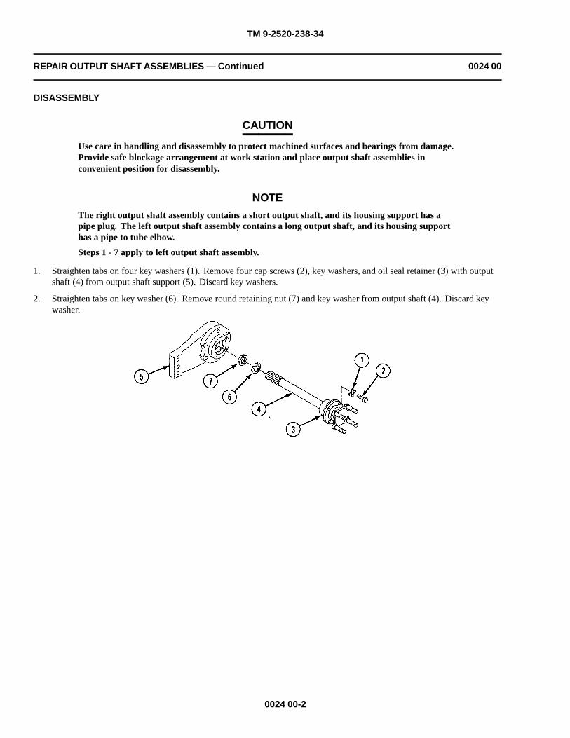
TM 9-2520-238-34
REPAIR OUTPUT SHAFT ASSEMBLIES — Continued 0024 00
DISASSEMBLY
CAUTION
Use care in handling and disassembly to protect machined surfaces and bearings from damage.Provide safe blockage arrangement at work station and place output shaft assemblies inconvenient position for disassembly.
NOTE
The right output shaft assembly contains a short output shaft, and its housing support has apipe plug. The left output shaft assembly contains a long output shaft, and its housing supporthas a pipe to tube elbow.
Steps 1 - 7 apply to left output shaft assembly.
1. Straighten tabs on four key washers (1). Remove four cap screws (2), key washers, and oil seal retainer (3) with outputshaft (4) from output shaft support (5). Discard key washers.
2. Straighten tabs on key washer (6). Remove round retaining nut (7) and key washer from output shaft (4). Discard keywasher.
0024 00-2
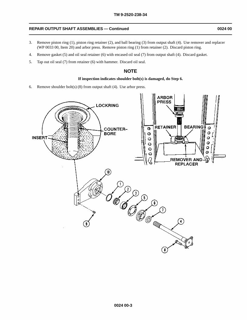
TM 9-2520-238-34
REPAIR OUTPUT SHAFT ASSEMBLIES — Continued 0024 00
3. Remove piston ring (1), piston ring retainer (2), and ball bearing (3) from output shaft (4). Use remover and replacer(WP 0033 00, Item 20) and arbor press. Remove piston ring (1) from retainer (2). Discard piston ring.
4. Remove gasket (5) and oil seal retainer (6) with encased oil seal (7) from output shaft (4). Discard gasket.
5. Tap out oil seal (7) from retainer (6) with hammer. Discard oil seal.
NOTE
If inspection indicates shoulder bolt(s) is damaged, do Step 6.
6. Remove shoulder bolt(s) (8) from output shaft (4). Use arbor press.
0024 00-3

TM 9-2520-238-34
REPAIR OUTPUT SHAFT ASSEMBLIES — Continued 0024 00
NOTE
If inspection indicates serrated lockring screw thread insert is damaged, do Step 7.
Inserts for both left and right output shaft assemblies are removed the same way.
7. Select drill with same diameter as inside serrations of insert (9) and drill to depth of counterbore in output shaft support(10). Drill at high speed. Drive in extractor tool and back out insert, turning to the left. As insert comes out, it will pushserrated lockring out. If lockring fails to come out as insert is removed, collapse lockring with punch and hammer.Remove lockring from output shaft support (10).
0024 00-4
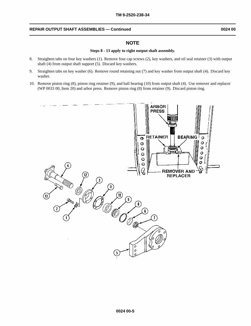
TM 9-2520-238-34
REPAIR OUTPUT SHAFT ASSEMBLIES — Continued 0024 00
NOTE
Steps 8 - 13 apply to right output shaft assembly.
8. Straighten tabs on four key washers (1). Remove four cap screws (2), key washers, and oil seal retainer (3) with outputshaft (4) from output shaft support (5). Discard key washers.
9. Straighten tabs on key washer (6). Remove round retaining nut (7) and key washer from output shaft (4). Discard keywasher.
10. Remove piston ring (8), piston ring retainer (9), and ball bearing (10) from output shaft (4). Use remover and replacer(WP 0033 00, Item 20) and arbor press. Remove piston ring (8) from retainer (9). Discard piston ring.
0024 00-5

TM 9-2520-238-34
REPAIR OUTPUT SHAFT ASSEMBLIES — Continued 0024 00
11. Remove gasket (11) and oil seal retainer (3) with encased oil seal (12) from output shaft (4). Discard gasket.
12. Tap out oil seal (12) from retainer (3) with hammer. Discard oil seal.
NOTEIf inspection indicates shoulder bolt(s) is damaged, do Step 13.
NOTEIf inspection indicates serrated lockring screw thread insert is damaged, do Step 7.
13. Remove bolt(s) (13) from base of output shaft (4). Use arbor press.
CLEANING
CLEAN, INSPECT, AND REPAIR
1. Before inspection, repair, or assembly, clean all parts of each output shaft assembly as described in (WP 0014 00).
2. Inspect all parts using general procedures described in (WP 0014 00). Check wear limits for minimum, maximum, andimportant clearances of new or rebuilt parts (page 0023 00-13).
0024 00-6

TM 9-2520-238-34
REPAIR OUTPUT SHAFT ASSEMBLIES — Continued 0024 00
3. Inspect the bore and machine groove in the piston ring retainer for wearing and deformation. Replace defective retainer.
4. Inspect screw thread inserts in output shaft supports for damaged threads and loose fit. Replace inserts that are loose orhave damaged threads.
ASSEMBLY
NOTE
Steps 1 - 13 apply to right output shaft assembly.
If serrated lockring screw thread insert in output shaft support was removed in page 0024 00-2,do Steps 1 - 3.
1. Remove lockring (1) from insert (2).
2. Install insert (2) into tapped hole of output shaft support (3) by turning insert to the right.
CAUTION
Do not drive lockring below top surface of insert. Insert threads may loosen.
3. Drive lockring (1) into tapped hole in output shaft support (3) until inserter tool touches surface. Lockring will be set atproper depth.
4. Thoroughly clean mating surface of new encased oil seal (4) with cleaning compound.
5. Apply a thin film of sealing compound to outer edge of oil seal (4).
0024 00-7

TM 9-2520-238-34
REPAIR OUTPUT SHAFT ASSEMBLIES — Continued 0024 00
CAUTION
To prevent damage to encased oil seal, do not press seal beyond face of bore. After installation,seal must be flush with outer surface.
6. Install oil seal (1) in oil seal retainer (2). Use remover and replacer (WP 0033 00, Item 24) and hammer.
NOTE
If shoulder bolt(s) was removed in page 0024 00-2, do Step 7.
7. Install new bolt(s) (3) in base of shaft (4) with flat side of bolts toward shoulder. Use arbor press.
8. Install new piston ring (5) on piston ring retainer (6).
9. Install oil seal retainer (2) with oil seal (1) installed, new gasket (7), ball bearing (8), and retainer (6) with piston ring (5)on shaft (4). Use remover and replacer (WP 0033 00, Item 20) and arbor press.
0024 00-8

TM 9-2520-238-34
REPAIR OUTPUT SHAFT ASSEMBLIES — Continued 0024 00
10. Install new key washer (9) and retaining nut (10) on shaft (4). Tighten nut. Bend tabs on key washer (9) over nut.
11. Thoroughly clean threads of four cap screws (11).
12. Apply light coat of antiseize compound to threads of cap screws (11).
13. Install retainer (6) with attached parts on output shaft support (12) with four new key washers (13) and cap screws (11).Tighten screws to 252-300 lb-in (28.5-33.9 N•m) torque. Use torque wrench and socket wrench set. Bend tabs on keywashers.
0024 00-9
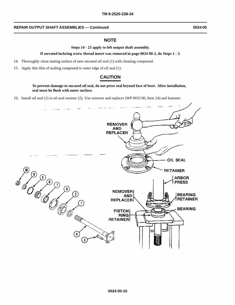
TM 9-2520-238-34
REPAIR OUTPUT SHAFT ASSEMBLIES — Continued 0024 00
NOTE
Steps 14 - 23 apply to left output shaft assembly.
If serrated lockring screw thread insert was removed in page 0024 00-2, do Steps 1 - 3.
14. Thoroughly clean mating surface of new encased oil seal (1) with cleaning compound.
15. Apply thin film of sealing compound to outer edge of oil seal (1).
CAUTION
To prevent damage to encased oil seal, do not press seal beyond face of bore. After installation,seal must be flush with outer surface.
16. Install oil seal (1) in oil seal retainer (2). Use remover and replacer (WP 0033 00, Item 24) and hammer.
0024 00-10

TM 9-2520-238-34
REPAIR OUTPUT SHAFT ASSEMBLIES — Continued 0024 00
NOTE
If shoulder bolt(s) was removed in page 0024 00-2, do Step 17.
17. Install shoulder bolt(s) (3) in base of shaft (4) with flat side of bolt(s) toward shoulder. Use arbor press.
18. Install new piston ring (5) on piston ring retainer (6).
19. Install retainer (2) with oil seal (1) installed, new gasket (8), ball bearing (7), and retainer (6) with piston ring (5) on shaft(4). Use remover and replacer (WP 0033 00, Item 20) and arbor press.
20. Install new key washer (9) and retaining nut (10) on shaft (4). Tighten nut. Bend key washer tabs on nut.
0024 00-11

TM 9-2520-238-34
REPAIR OUTPUT SHAFT ASSEMBLIES — Continued 0024 00
21. Thoroughly clean threads of four cap screws (1).
22. Apply light coat of antiseize compound to threads of cap screws (1).
23. Install retainer (2) on output shaft support (3) with four new key washers (4) and cap screws (1). Tighten screws to252-300 lb-in (28.5-33.9 N•m) torque. Use torque wrench and socket wrench set. Bend tabs on key washers.
0024 00-12

TM 9-2520-238-34
REPAIR OUTPUT SHAFT ASSEMBLIES — Continued 0024 00
WEAR LIMITS
1. See TM 9-214 to check bearings.
2. Check parts that have reference letters in figure.
0024 00-13

TM 9-2520-238-34
REPAIR OUTPUT SHAFT ASSEMBLIES — Continued 0024 00
3. Check the parts dimensions with chart below to determine replacement.
Table 1. LEFT AND RIGHT OUTPUT SHAFT ASSEMBLIES WEAR LIMITS
ReferenceLetter
Point of Measurement Size and Fit of New Parts Wear Limits
A Outside diameter at oil seal surface of shaft 1.9980 to 2.0020 1.9960
B Outside diameter at bearing surface of shaft 1.7716 to 1.7720 (*)(**)
C Inside diameter at seal surface of retainer 2.6850 to 2.6870 (*)(***)
D Inside diameter of bearing 1.7712 to 1.7717 (*)(**)
D-B Fit of bearing on shaft 0.0001L to 0.0008T (*)
E Outside diameter of bearing 3.3459 to 3.3465 (*)(**)
F Inside diameter at bearing surface of support 3.3464 to 3.3472 3.3477
F-E Fit of bearing in support 0.0013L to 0.0001T 0.0018L
G Inside diameter at piston ring surface of support 2.9370 to 2.9390 (****) 2.9450
* Must be within new parts dimensions.
** Measure only if there is visual indication of bearing turning.
*** Measure only if there is visual indication of seal turning in retainer.
**** Measure only if support has been reworked to remove grooves caused by sealing ring or to repair other damage.
END OF TASK
0024 00-14

TM 9-2520-238-34
REPLACE DIFFERENTIAL STEERING CONTROL ASSEMBLY 0025 00
THIS WORK PACKAGE COVERS:
Removal (page 0025 00-2).Cleaning (page 0025 00-3).Installation (page 0025 00-4).
INITIAL SETUP:
Maintenance Level
General Support
Tools and Special Tools
General mechanic’s tool kit (WP 0033 00, Item 37)Socket wrench set, 3/8 inch drive (WP 0033 00, Item 34)Torque wrench (WP 0033 00, Item 41)
Materials/Parts
Antiseize compound (WP 0034 00, Item 1)GasketKey washer
Personnel Required
Track Vehicle Repairer
References
See your -20
Equipment Condition
Steering control differential removed from carrier (seeyour -20)
Housing cover removed (WP 0021 00)Output shaft assembly removed (WP 0023 00)Right angle gearbox removed (WP 0027 00)
0025 00-1

TM 9-2520-238-34
REPLACE DIFFERENTIAL STEERING CONTROL ASSEMBLY — Continued 0025 00
REMOVAL
CAUTION
Use care during removal of steering unit assembly to prevent separation of brake hub fromsplined shaft.
1. Support shaft at each end of control assembly (1) and carefully remove steering control assembly from differentialhousing (2).
0025 00-2
Parts of the brake assembly may be coated with asbestos dust. Breathing this dust can harmpersonnel. Use a filter mask approved for use against asbestos dust. Never use compressed airor dry brush to clean these assemblies. Use an industrial type vacuum cleaner with ahigh-efficiency filter system to remove dust. Use water and a soft bristle brush or cloth toremove dirt or mud.
WARNING

TM 9-2520-238-34
REPLACE DIFFERENTIAL STEERING CONTROL ASSEMBLY — Continued 0025 00
2. Straighten tabs on key washer (3). Remove cap screw (4) and key washer holding gauge rod guide (5) to housing (2).Remove rod guide from nonmetallic grommet (6) in strainer (7). Discard key washer.
CLEANING
CLEAN, INSPECT, AND REPLACE
1. Check all parts for cracks, wear, and damage. Replace if needed.
0025 00-3

TM 9-2520-238-34
REPLACE DIFFERENTIAL STEERING CONTROL ASSEMBLY — Continued 0025 00
INSTALLATION
1. Install gauge rod guide (1) in housing (2). Install end of guide through grommet (3) in strainer (4) at bottom of housing.Apply a light coat of antiseize compound to clean threads of cap screw (5). Secure guide to housing bracket with newkey washer (6) and cap screw (5). Tighten screw to 252-300 lb-in (29-34 N•m). Use torque wrench and socket set.
2. Support shaft at each end of control assembly (7) and carefully install steering control assembly on differentialhousing (2).
END OF TASK
0025 00-4

TM 9-2520-238-34
REPAIR DIFFERENTIAL STEERING CONTROL ASSEMBLY 0026 00
THIS WORK PACKAGE COVERS:
Disassembly (page 0027 00-2Cleaning (page 0027 00-5).Assembly (page 0027 00-6).Wear Limits (page 0027 00-12).
INITIAL SETUP:
Maintenance Level
General Support
Tools and Special Tools
General mechanic’s tool kit (WP 0033 00, Item 37)Hammer, soft plastic (WP 0033 00, Item 10)Arbor press (WP 0033 00, Item 16)Mechanical puller kit (WP 0033 00, Item 17)Socket wrench set, 3/8 inch drive (WP 0033 00, Item 34)Torque wrench (WP 0033 00, Item 41)Torque wrench (WP 0033 00, Item 43)Vernier height gage (WP 0033 00, Item 8)
Materials/Parts
Cotter pin (26)Cotter pin (6)Woodruff key (6)
Personnel Required
Track Vehicle Repairer
References
See your -10See your -20TM 9-214
Equipment Condition
Differential steering control assembly removed fromdifferential (WP 0025 00).
0026 00-1

TM 9-2520-238-34
REPAIR DIFFERENTIAL STEERING CONTROL ASSEMBLY — Continued 0026 00
DISASSEMBLY
WARNING
Parts of the brake assembly may be coated with asbestos dust. Breathing this dust can harmpersonnel. Use a filter mask approved for use against asbestos dust. Never use compressed airor dry brush to clean these assemblies. Use an industrial type vacuum cleaner with ahigh-efficiency filter system to remove dust. Use water and a soft bristle brush or cloth toremove dirt or mud.
1. Remove bearing thrust washer (1), brake drum hub (2) with brake drum (3) attached, and sleeve bearing (4) from splineddrive shaft on control flange assembly (5).
NOTE
If inspection indicates that brake drum hub or brake drum require replacement, do Step 2.
2. Remove 10 cotter pins (6), slotted nuts (7), 20 washers (8), and 10 cap screws (9) securing brake drum hub (2) to brakedrum (3). Separate hub and drum. Discard cotter pins.
3. Inspect 10 cap screws (9) to determine grade type. If screws are not grade 8 (six radial marks on screw heads), discardscrews.
0026 00-2

TM 9-2520-238-34
REPAIR DIFFERENTIAL STEERING CONTROL ASSEMBLY — Continued 0026 00
4. Remove ball bearing (1) from brake flange (2). Use mechanical puller.
5. Remove bearing thrust washer (3), sleeve bearing (4), and brake drum hub (5) with attached brake drum (6) from brakeflange assembly (2).
NOTEIf inspection indicates that brake drum hub or brake drum require replacement, do Step 6.
6. Remove 10 cotter pins (7), slotted nuts (8), 20 washers (9), and 10 cap screws (10) securing brake drum hub (5) to brakedrum (6). Separate hub and drum. Discard cotter pins.
0026 00-3

TM 9-2520-238-34
REPAIR DIFFERENTIAL STEERING CONTROL ASSEMBLY — Continued 0026 00
7. Remove six cotter pins (1), slotted nuts (2), and washers (3) holding external spur gears (4) to gear shafts (5) betweencontrol flange assembly (6) and brake flange assembly (7). Discard cotter pins.
8. Remove six spur gears (4) from gear shafts (5). Use mechanical puller. Remove six woodruff keys (8) from gear shafts.Discard keys.
9. Remove six cotter pins (9), slotted nuts (10), and machine bolts (11) holding control flange assembly (6) to brake flangeassembly (7). Separate control flange and brake flange assemblies. Use soft hammer. Discard cotter pins.
10. Remove spur gear (12) and six gear shafts (5) from differential spider (13).
11. Separate spur gear (14) and spider (13) from control flange assembly (6). Use soft hammer.
0026 00-4
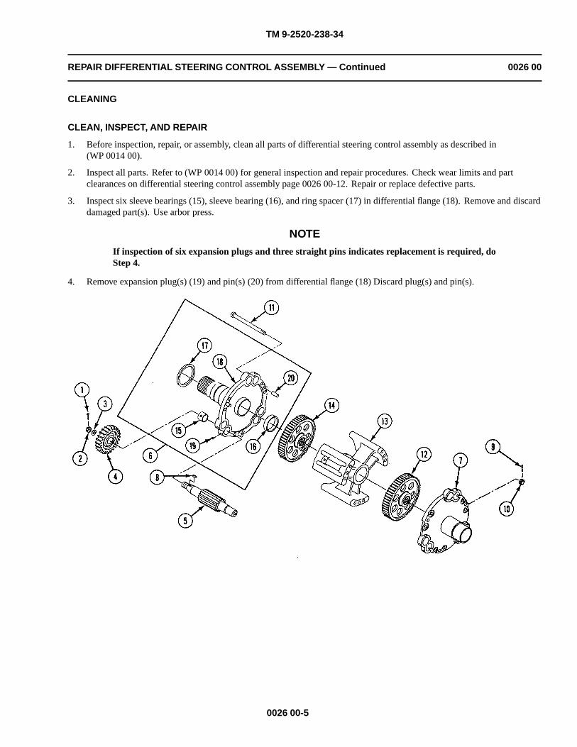
TM 9-2520-238-34
REPAIR DIFFERENTIAL STEERING CONTROL ASSEMBLY — Continued 0026 00
CLEANING
CLEAN, INSPECT, AND REPAIR
1. Before inspection, repair, or assembly, clean all parts of differential steering control assembly as described in(WP 0014 00).
2. Inspect all parts. Refer to (WP 0014 00) for general inspection and repair procedures. Check wear limits and partclearances on differential steering control assembly page 0026 00-12. Repair or replace defective parts.
3. Inspect six sleeve bearings (15), sleeve bearing (16), and ring spacer (17) in differential flange (18). Remove and discarddamaged part(s). Use arbor press.
NOTE
If inspection of six expansion plugs and three straight pins indicates replacement is required, doStep 4.
4. Remove expansion plug(s) (19) and pin(s) (20) from differential flange (18) Discard plug(s) and pin(s).
0026 00-5

TM 9-2520-238-34
REPAIR DIFFERENTIAL STEERING CONTROL ASSEMBLY — Continued 0026 00
5. Inspect ring spacer (1), six sleeve bearings (2), and sleeve bearing (3) in differential flange (4). Remove and discarddamaged part(s). Use arbor press.
NOTE
If inspection of six expansion plugs and three straight pins indicates replacement is required, doStep 6.
6. Remove expansion plug(s) (5) and pin(s) (6) from differential flange (4). Discard plug(s) and/or pin(s).
ASSEMBLY
NOTEIf any of the three straight pins or six expansion plugs were removed from differential flange inpage 0027 00-5 above, do Step 1.
1. Install new pin(s) (6) and/or new expansion plug(s) (5) in differential flange (4). Stake each pin(s) four places. Stakeeach plug(s) two places.
NOTEIf sleeve bearings or ring spacer were removed from differential flange in page 0026 00-5 above,do Step 2.
2. Install new sleeve bearing (3), sleeve bearing(s) (2), and/or ring spacer (1) in differential flange (4). Use arbor press.
0026 00-6

TM 9-2520-238-34
REPAIR DIFFERENTIAL STEERING CONTROL ASSEMBLY — Continued 0026 00
NOTE
If any of three straight pins or six expansion plugs were removed from differential flange inpage 0026 00-5 above, do Step 3.
3. Install new straight pin(s) (1) and/or new expansion plug(s) (2) in differential flange (3). Stake each plug(s) two places.
NOTEIf ring spacer, or sleeve bearings were removed from differential flange in page 0026 00-5 above,do Step 4.
4. Install new ring spacer (4), sleeve bearing (5), and/or sleeve bearing(s) (6) in differential flange (3). Use arbor press.
5. Install differential spider (7) and spur gear (8) on control flange assembly (9).
0026 00-7
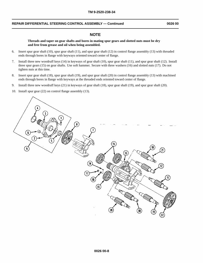
TM 9-2520-238-34
REPAIR DIFFERENTIAL STEERING CONTROL ASSEMBLY — Continued 0026 00
NOTE
Threads and taper on gear shafts and bores in mating spur gears and slotted nuts must be dryand free from grease and oil when being assembled.
6. Insert spur gear shaft (10), spur gear shaft (11), and spur gear shaft (12) in control flange assembly (13) with threadedends through bores in flange with keyways oriented toward center of flange.
7. Install three new woodruff keys (14) in keyways of gear shaft (10), spur gear shaft (11), and spur gear shaft (12). Installthree spur gears (15) on gear shafts. Use soft hammer. Secure with three washers (16) and slotted nuts (17). Do nottighten nuts at this time.
8. Insert spur gear shaft (18), spur gear shaft (19), and spur gear shaft (20) in control flange assembly (13) with machinedends through bores in flange with keyways at the threaded ends oriented toward center of flange.
9. Install three new woodruff keys (21) in keyways of gear shaft (18), spur gear shaft (19), and spur gear shaft (20).
10. Install spur gear (22) on control flange assembly (13).
0026 00-8

TM 9-2520-238-34
REPAIR DIFFERENTIAL STEERING CONTROL ASSEMBLY — Continued 0026 00
11. Install brake flange assembly (1) on control flange assembly (2) with six gear shafts (3) inserted through bores indifferential flange (4). Secure flange (1) and flange (2) together with six machine bolts (5) and slotted nuts (6). Tightennuts to 65-70 lb-ft (88-95 N•m) torque. Use torque wrench (WP 0033 00, Item 43). Install six new cotter pins (7).
12. Install three external spur gears (8) on gear shafts (3). Use soft hammer. Secure with three washers (9) and slottednuts (10).
13. Tighten six slotted nuts (10) to 140-160 lb-ft (190-217 N•m) torque. Use torque wrench (WP 0033 00, Item 43). Installsix new cotter pins (11).
14. Install sleeve bearing (12) on brake flange assembly (1) with grooves pointing to the left.
0026 00-9
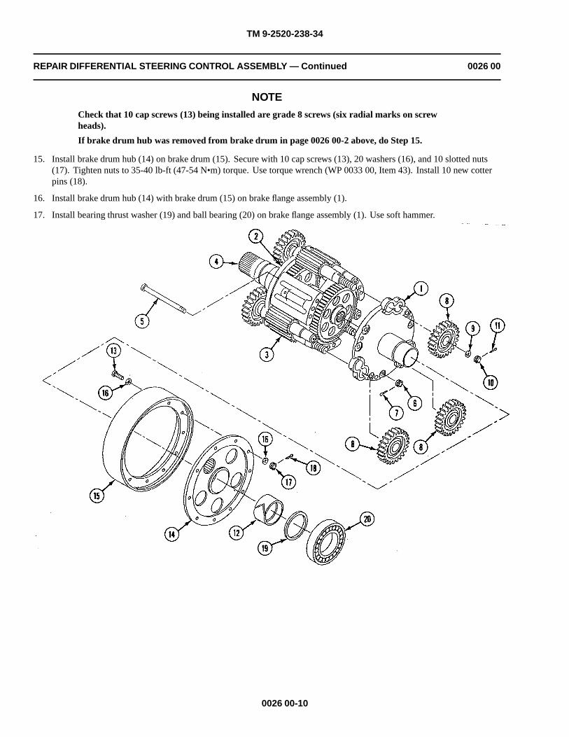
TM 9-2520-238-34
REPAIR DIFFERENTIAL STEERING CONTROL ASSEMBLY — Continued 0026 00
NOTE
Check that 10 cap screws (13) being installed are grade 8 screws (six radial marks on screwheads).
If brake drum hub was removed from brake drum in page 0026 00-2 above, do Step 15.
15. Install brake drum hub (14) on brake drum (15). Secure with 10 cap screws (13), 20 washers (16), and 10 slotted nuts(17). Tighten nuts to 35-40 lb-ft (47-54 N•m) torque. Use torque wrench (WP 0033 00, Item 43). Install 10 new cotterpins (18).
16. Install brake drum hub (14) with brake drum (15) on brake flange assembly (1).
17. Install bearing thrust washer (19) and ball bearing (20) on brake flange assembly (1). Use soft hammer.
0026 00-10

TM 9-2520-238-34
REPAIR DIFFERENTIAL STEERING CONTROL ASSEMBLY — Continued 0026 00
18. Install sleeve bearing (1) on control flange assembly (2) with grooves pointing to the right.
NOTE
Check that 10 cap screws being installed are grade 8 screws (six radial marks on screw heads).
If brake drum hub was removed from brake drum in page 0026 00-2 above, do Step 19.
NOTE
If sleeve bearing (3120-00-782-4191, 8756536) is installed on differential spider, inside diameterof spider will be 2.249 to 2.251 inches (5.71 cm).
NOTE
If spider is equipped with sleeve bearing (3120-00-782-4191, 8756536), the fit of spider on gearhub will be 0.0010L to 0.00040L.
19. Install brake drum hub (3) on brake drum (4). Secure with 10 cap screws (5), 20 washers (6), and 10 slotted nuts (7).Tighten nuts to 420-480 lb-in (47-54 N•m) torque. Use torque wrench (WP 0033 00, Item 41). Install 10 new cotterpins (8).
20. Install brake drum hub (3) with attached brake drum (4) on control flange assembly (2).
21. Install bearing thrust washer (9) on drive shaft of control flange assembly (2).
0026 00-11

TM 9-2520-238-34
REPAIR DIFFERENTIAL STEERING CONTROL ASSEMBLY — Continued 0026 00
WEAR LIMITS
1. See TM 9-214 to check bearings.
2. Check parts that have reference letters in figure.
0026 00-12

TM 9-2520-238-34
REPAIR DIFFERENTIAL STEERING CONTROL ASSEMBLY — Continued 0026 00
3. Check the parts dimensions with chart below to determine replacement.
Table 1. DIFFERENTIAL STEERING CONTROL ASSEMBLY WEAR LIMITS
ReferenceLetter
Point of Measurement Size and Fit of New Parts Wear Limits
A Thickness of thrust washer 0.2180 to 0.2220 (*)
B Inside diameter of brake drum sleeve bearing 3.2590 to 3.2600 (*)
C Inside diameter of flange bushing 2.2490 to 2.2505 (*)
D Inside diameter of spider 2.253 to 2.255 (*)(***)
With sleeve bearing 8756536 installed 2.249 to 2.251
E Outside diameter at bearing surface of gear shaft 1.0550 to 1.0560 (*)
F Inside diameter of flange bushing 1.0600 to 1.0610 (*)
F-E Fit of bushing on gear shaft 0.0040L to 0.0060L (**) 0.0080L
G Inside diameter of bearing 2.9522 to 2.9528 (*)(****)
H Outside diameter of bearing 5.1173 to 5.1181 (*)(****)
H-I Fit of bearing in housing 0.0016L to 0.002T
J Outside diameter of drum 13.175 to 13.185 (1)
K Outside diameter of bearing surface of flange hub 2.9527 to 2.9533 (*)
K-G Fit of bearing on flange hub 0.0001L to 0.0011T (*)
L Outside diameter of bearing suface of flange hub 3.2500 to 3.2510 (*)
L-B Fit of sleeve bearing on flange hub 0.0080L to 0.0100L (**) 0.0150L
M Outside diameter of gear hub 2.2470 to 2.2480 (*)(***)
M-C Fit of bushing on gear hub 0.0010L to 0.0035L 0.0065L
M-D Fit of spider on gear hub 0.005L to 0.0080L 0.0100L
With sleeve bearing 8756536 installed in spider 0.0010L to 0.0040L
(1) Machined drum wall thickness 0.250 inches (0.64 mm).
* Must be within new parts dimensions.
** Wear is allowed on either or both mating parts as long as fit is within specified limit.
*** Measure only if there is visual indication of wear or damage.
**** Measure only if there is visual indication of bearing turning.
END OF TASK
0026 00-13/14 blank


TM 9-2520-238-34
REPLACE DIFFERENTIAL RIGHT ANGLE GEARBOX 0027 00
THIS WORK PACKAGE COVERS:
Removal (page 0027 00-2).Cleaning (page 0027 00-14).Installation (page 0027 00-3).
INITIAL SETUP:
Maintenance Level
General Support
Tools and Special Tools
General mechanic’s tool kit (WP 0033 00, Item 37)Socket wrench set (WP 0033 00, Item 34)Torque wrench (WP 0033 00, Item 41)
Materials/Parts
Antiseize compound (WP 0035 00, Item 1)Petrolatum (WP 0035 00, Item 11)Packing
Personnel Required
Track Vehicle Repairer
References
See your -20
Equipment Condition
Steering control differential removed from carrier (seeyour -20)
Left output shaft removed (WP 0023 00)
0027 00-1

TM 9-2520-238-34
REPLACE DIFFERENTIAL RIGHT ANGLE GEARBOX — Continued 0027 00
REMOVAL
1. Remove right angle gearbox (1) from housing (2) as follows. Remove 11 cap screws (3) and washers (4) holdinggearbox (1) to housing (2). Remove loop clamp (5) and hose (6) from gearbox.
2. Remove hose (6) from adapter (7).
3. Install two cap screws (3) in threaded jack screw holes, and tighten screws uniformly to separate gearbox (1) fromhousing (2). Remove cap screws. Remove packing (8) from gearbox and discard packing. Remove thrust washer (9)from steering unit assembly (10).
CLEANING
CLEAN, INSPECT, AND REPLACE
1. Clean all parts, and check for cracks, wear, and damage. Replace if needed.
0027 00-2

TM 9-2520-238-34
REPLACE DIFFERENTIAL RIGHT ANGLE GEARBOX — Continued 0027 00
INSTALLATION
1. Install right angle gearbox (1) on differential housing (2). Install thrust washer (3) on shaft of steering control assembly(4). Lubricate new packing (5) with petrolatum and install packing on right angle gearbox.
2. Install hose (6) on adapter (7).
3. Install loop clamp (8) on nonmetallic hose (6). Clean threads of screws (9) thoroughly. Apply a light coat of antiseizecompound to clean threads of 11 cap screws (9). Place right angle gearbox and loop clamp (8) with attached hose (6) onhousing. Secure with 11 washers (10) and cap screws (9). Tighten screws to 252-300 lb-in (26-34 N•m) torque. Usetorque wrench and socket set.
END OF TASK
0027 00-3/4 blank


TM 9-2520-238-34
REPAIR DIFFERENTIAL RIGHT ANGLE GEARBOX 0028 00
THIS WORK PACKAGE COVERS:
Disassembly (page 0028 00-2).Cleaning (page 0028 00-8).Assembly (page 0028 00-9).Wear Limits (page 0028 00-21).
INITIAL SETUP:
Maintenance Level
General Support
Tools and Special Tools
General mechanic’s tool kit (WP 0033 00, Item 37)Bearing inserter (WP 0033 00, Item 1)C-clamp (WP 0033 00, Item 3)Soft plastic hammer (WP 0033 00, Item 10)Dial indicator gage (WP 0033 00, Item 12)Arbor press (WP 0033 00, Item 16)Mechanical puller kit (WP 0033 00, Item 17)Remover/Replacer (WP 0033 00, Item 21)Remover/Replacer (WP 0033 00, Item 23)Remover/Replacer (WP 0033 00, Item 24)Jack screw (2) (WP 0033 00, Item 30)Differential backlash tool (WP 0033 00, Item 36)Torque wrench (WP 0033 00, Item 39)Torque wrench (WP 0033 00, Item 41)Torque wrench (WP 0033 00, Item 43)Vernier height gage (WP 0033 00, Item 8)
Materials/Parts
Antiseize compound (WP 0035 00, Item 1)Engine oil (WP 0035 00, Item 5)Grease (WP 0035 00, Item 6)Non-electrical wire (WP 0035 00, Item 9)Petrolatum (WP 0035 00, Item 10)Sealing compound (WP 0035 00, Item 12)Sealing compound (WP 0035 00, Item 13)Key washer (26)Key washer
Personnel Required
Track Vehicle Repairer
References
TM 9-214
Equipment Condition
Differential right angle gearbox removed fromdifferential assembly (WP 0027 00)
0028 00-1

TM 9-2520-238-34
REPAIR DIFFERENTIAL RIGHT ANGLE GEARBOX — Continued 0028 00
DISASSEMBLY
1. Remove lockwire (1) (four places), eight cap screws (2), and washers (3) holding adapter plate (4) to gearbox housing(5). Discard lockwire.
2. Bend tabs on two key washers (6). Remove two cap screws (7) and key washers from plate (4). Discard key washers.
0028 00-2

TM 9-2520-238-34
REPAIR DIFFERENTIAL RIGHT ANGLE GEARBOX — Continued 0028 00
3. Install two 3/8 x 16 cap screws 2 inches (5 cm) long (minimum length) in jacking holes where screws were removed inStep 2. Tighten screws uniformly to separate plate (4) and output hub (8) with attached parts as an assembly fromhousing (5).
4. Remove laminated shim (9), packing (10), and gasket (11) from plate (4). Discard shim, packing, and gasket.
5. Bend tabs on eight key washers (12). Remove eight cap screws (13), key washers, bearing retainer (14), and laminatedshim (15) from plate (4). Discard key washers.
6. Straighten tabs on key washer (16). Remove round nut (17) and key washer from hub (8). Discard key washer.
0028 00-3

TM 9-2520-238-34
REPAIR DIFFERENTIAL RIGHT ANGLE GEARBOX — Continued 0028 00
7. Bend tabs on eight key washers (1). Remove eight cap screws (2) and key washers holding bearing housing (3) togearbox housing (4). Remove bearing housing with input bevel gear (5) as an assembly. Discard key washers.
8. Remove laminated shim (6) and packing (7) from bearing housing (3). Discard shim and packing.
NOTEIf inspection indicates that outer race of ball bearing requires replacement, do Step 9.
9. Remove inner retaining ring (8), outer race of bearing (9), and outer retaining ring (8) from gearbox housing (4). Discardouter race.
NOTE
Bearing inner race (10) and outer race (9) must be replaced as matched set.
10. If inspection indicates that bearing inner race (10) requires replacement, remove retaining ring (11) and inner race frombevel gear (5). Use remover and replacer (WP 0033 00, Item 24) and mechanical puller (WP 0033 00, Item 17). Discardinner race.
0028 00-4

TM 9-2520-238-34
REPAIR DIFFERENTIAL RIGHT ANGLE GEARBOX — Continued 0028 00
11. Bend tabs on eight key washers (12). Remove eight cap screws (13), key washers, and oil seal retainer (14) from gearboxhousing (3). Remove laminated shim (15) and packing (16). Discard key washers, shim, and packing.
12. Remove packing (17), bevel gear (5), and encased oil seal (18) from retainer (14). Discard packing and oil seal.
13. Straighten tabs on key washer (19). Remove round nut (20) key washer, and spacer (21) from bevel gear (5). Discard keywasher.
0028 00-5

TM 9-2520-238-34
REPAIR DIFFERENTIAL RIGHT ANGLE GEARBOX — Continued 0028 00
NOTE
If inspection indicates that bevel gear requires replacement, do Step 14.
14. Remove bevel gear (1) from outer bearing housing (2). Attach clamp around bearing (3).Use arbor press, remover and replacer (WP0033 00, Item 24) and gear inserter. Remove clamp.
0028 00-6

TM 9-2520-238-34
REPAIR DIFFERENTIAL RIGHT ANGLE GEARBOX — Continued 0028 00
NOTE
If inspection indicates that tapered roller bearings require replacement, or if bevel gear wasremoved, do Step 15.
15. Remove bearings (3) from outer bearing housing (2). Use remover and replacer (WP 0033 00, Item 24). Discardbearings.
NOTE
If inspection indicates that output bevel gear, hub, or ball bearing require replacement, do Step16 and Step 17.
Inspect eight cap screws to determine grade type. If screws are not grade 8 (six radial marks onscrew heads), discard screws.
16. Remove lockwire (4) (four places), eight cap screws (5), and washers (6) holding gear (7) to hub (8). Remove gear.Discard lockwire. If gear is damaged, discard gear.
17. Press bearing (9) from hub (8). Discard bearing.
0028 00-7

TM 9-2520-238-34
REPAIR DIFFERENTIAL RIGHT ANGLE GEARBOX — Continued 0028 00
NOTE
If inspection indicates that ball bearing requires replacement, do Step 18.
18. Remove ball bearing (1) from gearbox housing (2). Use a suitable bearing puller.
NOTE
If inspection indicates resilient mount requires replacement, do Step 19.
19. Remove resilient mount (3) from gearbox housing (2). Use remover and replacer (WP 0033 00, Item 21).
NOTE
If inspection indicates that eye bolt requires replacement, do Step 20.
20. Remove eye bolt (4) from gearbox housing (2). Discard eye bolt.
NOTE
If inspection indicates that pin(s) require replacement, do Step 21.
21. Remove pin(s) (5) from housing (2). Discard pins.
CLEANING
CLEAN, INSPECT, AND REPAIR
1. Before inspection, repair, or assembly, clean all parts of each output shaft assembly. See WP 0014 00.
2. Inspect all parts. Refer to (WP 0014 00) for general inspection and repair procedures. Check for minimum, maximum,and important clearances of new or rebuilt parts and for wear limits to which a part may be worn before replacement isrequired (page 0028 00-21).
0028 00-8

TM 9-2520-238-34
REPAIR DIFFERENTIAL RIGHT ANGLE GEARBOX — Continued 0028 00
ASSEMBLY
1. If pin(s) (5) was removed, install pin(s) in gearbox housing (2) so they protrude 19/32±1/32 inch (1.4±.076 cm).
2. If eye bolt (4) was removed, install new eye bolt in gearbox housing (2).
3. If resilient mount (3) was removed, install new resilient mount in gearbox housing (2). Use remover and replacer(WP 0033 00, Item 21).
4. If ball bearing (1) was removed, install new ball bearing in gearbox housing (2). Use arbor press and 5 inch (13 cm)diameter ring (1 inch (2.5 cm) minimum length).
0028 00-9

TM 9-2520-238-34
REPAIR DIFFERENTIAL RIGHT ANGLE GEARBOX — Continued 0028 00
NOTE
If both tapered roller bearings were removed in page 0028 00-2, do Steps 5 - 8.
To aid in installation of bearings, heat housing to 250�-300�F (121�-149�C) and freeze bearingcups.
5. Install cup (1) of inner roller bearing in bearing housing (2). Use remover and replacer (WP 0034 00, Item 24) andbearing inserter.
6. Insert shaft of bevel gear (3) into bearing housing (2).
7. Heat cone (4) of inner bearing and cone (5) of outer bearing to 240�-260�F (116�-127�C). Install cones in bearinghousing (2). Use remover and replacer (WP 0033 00, Item 24) and bearing inserter.
8. Install cup (6) of outer bearing in bearing housing (2). Use remover and replacer (WP 0033 00, Item 24) and bearinginserter.
0028 00-10

TM 9-2520-238-34
REPAIR DIFFERENTIAL RIGHT ANGLE GEARBOX — Continued 0028 00
9. If inner race (7) of ball bearing was removed, install new race in bevel gear (3). Use remover and replacer (WP 0033 00,Item 24) and bearing inserter.
10. Install ring spacer (8), new key washer (9), and round nut (10) on bevel gear (3). Bend tangs on key washer.
11. Apply a thin film of sealing compound (WP 0035 00, Item 12) or (WP 0035 00, Item 13) to outer edge of encased oilseal (11).
CAUTION
To prevent damage to encased oil seal, do not press seal beyond face of bore. After installation,seal must be flush with outer surface within .032 inch (.081 cm).
12. Install encased oil seal (11) in oil seal retainer (12). Use remover and replacer (WP 0033 00, Item 24) and hammer.
0028 00-11

TM 9-2520-238-34
REPAIR DIFFERENTIAL RIGHT ANGLE GEARBOX — Continued 0028 00
13. Lubricate new packing (13) with grease or petrolatum. Install packing on shaft of bevel gear (3).
14. Install retaining ring (14) on shaft of bevel gear (3).
15. Install outer race of bearing (7) with two retaining rings (15) in gearbox housing (16).
16. Lubricate six cap screws (17) and (18) with engine oil.
0028 00-12

TM 9-2520-238-34
REPAIR DIFFERENTIAL RIGHT ANGLE GEARBOX — Continued 0028 00
17. Without shim installed, place bearing housing (1) on gearbox housing (2). Secure with two cap screws (3) positioned180 degrees apart. Tighten screws to 10-25 lb-in (2 N•m) torque. Use torque wrench (WP 0033 00, Item 39).
18. Place oil seal retainer (4) on bearing housing (1). Secure with four cap screws (5) spaced 90 degrees apart. Tightenscrews to 10-25 lb-in (2 N•m) torque. Use torque wrench (WP 0033 00, Item 39).
19. Measure and record gap between retainer (4) and bearing housing (1) at four equal places around retainer and determinethe average of these readings. Peel shim (6) to this thickness or to the next laminate thinner.
20. Remove four cap screws (5) and retainer (4) from bearing housing (1).
21. Lubricate new packing (7) with grease or petrolatum. Install packing on retainer (4).
22. Clean threads of eight cap screws (5). Apply light coat of antiseize compound to threads at installation.
23. Place peeled shim (6) and retainer (4) on bearing housing (1). Secure with eight new key washers (8) and cap screws (5).Tighten screws to 252-300 lb-in (28-34 N•m) torque. Use torque wrench (WP 0033 00, Item 41). Do not bend tabs onkey washers at this time.
0028 00-13
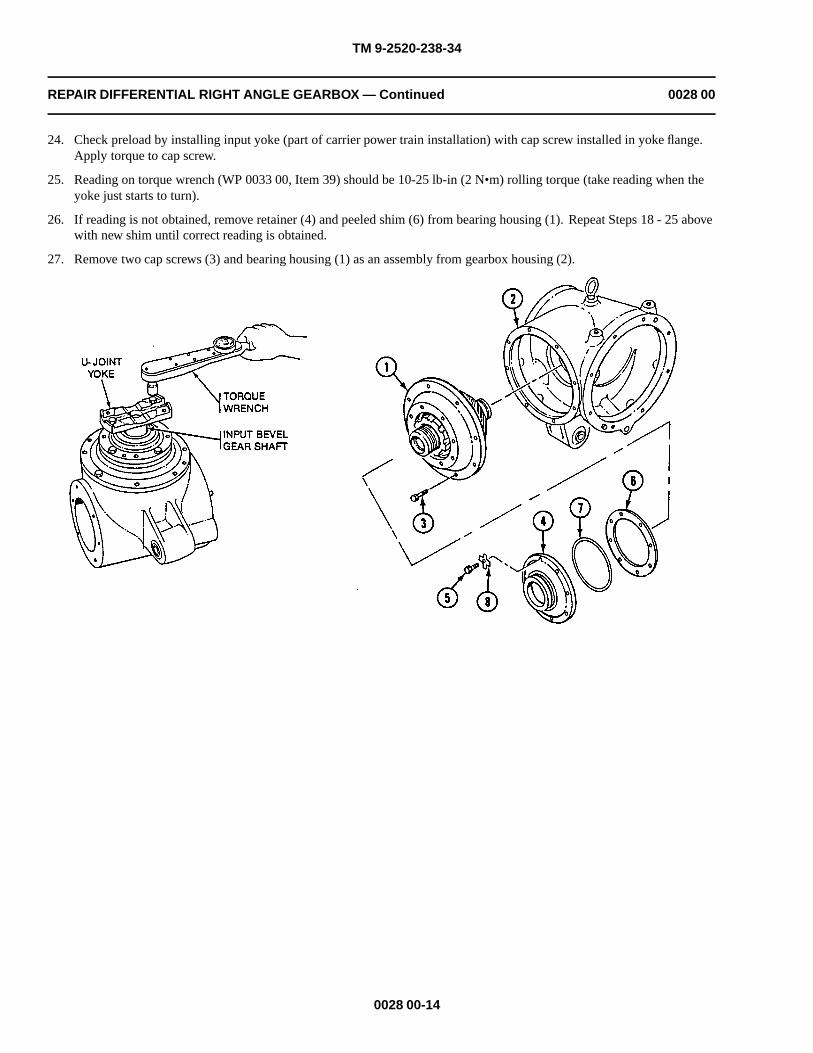
TM 9-2520-238-34
REPAIR DIFFERENTIAL RIGHT ANGLE GEARBOX — Continued 0028 00
24. Check preload by installing input yoke (part of carrier power train installation) with cap screw installed in yoke flange.Apply torque to cap screw.
25. Reading on torque wrench (WP 0033 00, Item 39) should be 10-25 lb-in (2 N•m) rolling torque (take reading when theyoke just starts to turn).
26. If reading is not obtained, remove retainer (4) and peeled shim (6) from bearing housing (1). Repeat Steps 18 - 25 abovewith new shim until correct reading is obtained.
27. Remove two cap screws (3) and bearing housing (1) as an assembly from gearbox housing (2).
0028 00-14

TM 9-2520-238-34
REPAIR DIFFERENTIAL RIGHT ANGLE GEARBOX — Continued 0028 00
28. Install ball bearing (1) in adapter plate (2). Use a soft plastic hammer.
29. Place bearing (1) with plate (2) to hub (3) and install bearing. Use remover and replacer (WP 0033 00, Item 23) andhammer.
30. Secure hub (3) to bearing (1) with new key washer (4) and round nut (5). Bend tangs on key washer.
31. Lubricate four cap screws (6) with engine oil.
32. Without shim (7) installed, place bearing retainer (8) on plate (2). Secure with four cap screws (6) spaced 90 degreesapart. Tighten screws to 14-16 lb-in (1 N.m) torque. Use torque wrench (WP 0033 00, Item 39).
33. Measure and record gap between retainer (8) and plate (2) at four equal places around retainer and determine the averageof the readings and subtract .002-.003 inch (.005-.008 cm) to obtain required deflection in retainer (8). Peel shim (7) tothis thickness or to the next laminate thinner.
34. Remove four cap screws (6) and retainer (8) from plate (2).
35. Clean threads of eight cap screws (6). Apply light coat of antiseize compound to threads at installation.
36. Place peeled shim (7) and retainer (8) on plate (2). Secure with eight new key washers (9) and cap screws (6). Tightenscrews to 252-300 lb-in (28-34 N•m) torque. Use torque wrench (WP 0033 00, Item 41). Bend tabs on key washers.
0028 00-15

TM 9-2520-238-34
REPAIR DIFFERENTIAL RIGHT ANGLE GEARBOX — Continued 0028 00
NOTE
If output bevel gear was removed in page 0029 00-2, do Steps 37 - 39.
Check that eight cap screws being installed are grade 8 screws (six radial marks on screwheads).
37. Clean threads of eight cap screws (10) and lubricate threads with engine oil.
38. Position bevel gear (11) to hub (3) and secure with eight washers (12) and cap screws (10). Tighten screws to 95-100lb-ft (129-137 N•m) torque. Use torque wrench (WP 0033 00, Item 43).
39. Install new lockwire (13) between adjacent screws (four places).
40. Lubricate new packing (14) with grease or petrolatum. Install new gasket (15) and packing on plate (2).
0028 00-16

TM 9-2520-238-34
REPAIR DIFFERENTIAL RIGHT ANGLE GEARBOX — Continued 0028 00
41. Measure distance between face of bevel gear (1) and adapter plate (2) (dimension Y) at three places 120 degrees apart.Take the average of these readings and record.
42. Note true mounting distance etched on face of gear (1) (dimension X) and add the dimension recorded above. Subtract5.002 inches (12.7 cm) from the resulting value and record as the thickness of shim. Peel shim (3) to this thickness.
NOTE
Check that eight cap screws being installed are grade 8 screws (six radial marks on screwheads).
43. Lubricate four cap screws (4) with engine oil.
0028 00-17

TM 9-2520-238-34
REPAIR DIFFERENTIAL RIGHT ANGLE GEARBOX — Continued 0028 00
NOTE
ST = X + Y - 5.002 inch
ST = Thickness of shim (3)
X = Etched true mounting distance on face of bevel gear (1)
Y = Measured distance after assembly of bevel gear (1) and adapter plate (2)
44. Place peeled shim (3) and output assembly (adapter plate (2) with attached parts) on gearbox housing (5). Secure withfour screws (4) spaced 90 degrees apart. Tighten screws to 14-16 lb-in (1.7 N•m) torque. Use torque wrench(WP 0033 00, Item 39).
0028 00-18

TM 9-2520-238-34
REPAIR DIFFERENTIAL RIGHT ANGLE GEARBOX — Continued 0028 00
45. Lubricate two cap screws (1) with engine oil.
46. Install peeled shim (2) and input assembly (bearing housing (3) with attached parts) on gearbox housing (4). Secure withtwo cap screws (1) spaced 180 degrees apart. Tighten screws to 14-16 lb-in (1.7 N•m) torque. Use torque wrench(WP 0033 00, Item 39).
47. Install dial indicator gage (WP 0033 00, Item 12) and fabricated differential backlash tool on output assembly (adapterplate (5) with attached parts). Install gage feeler rod into slot on tool arm.
48. Hold oil seal retainer (6) on input assembly and rotate plate (5) on output assembly and check gauge for backlash.Backlash should read .006-.011 inch (.15-.28 mm).
49. If backlash is too high, remove laminate(s) from shim (2). Adjust shim until correct reading is obtained.
50. Remove two cap screws (1) and separate input assembly from gearbox housing (4).
0028 00-19

TM 9-2520-238-34
REPAIR DIFFERENTIAL RIGHT ANGLE GEARBOX — Continued 0028 00
51. Remove four cap screws (1).
52. Clean 10 cap screw threads of cap screws(1), cap screws(2), and 2 alignment pins (3).
53. Apply a thin film of sealing compound (WP 0035 00, Item 12) or (WP 0035 00, Item 13) to 10 cap screw threads of capscrews (1), cap screws(2) and 2 dowel holes marked G on surfaces in contact with adapter plate (4).
54. Secure output assembly on gearbox housing (5) with two new key washers (6), cap screws (2), eight washers (7), and capscrews (1). Tighten screws (1) to 300-360 lb-in (34-41 N•m) torque. Use torque wrench (WP 0033 00, Item 41). Bendtabs on two key washers.
55. Secure eight cap screws (1) in pairs with new lockwire (8) (four places with 13 inches (33 cm) minimum length of wirerequired for each place).
56. Lubricate new preformed packing (9) with grease or petrolatum. Install packing on bearing housing (10).
57. Clean threads of eight cap screws (11). Apply light coat of antiseize compound to threads at installation.
58. Secure input assembly on gearbox housing (5) with eight new key washers (12) and cap screws (11). Tighten screws to252-300 lb-in (28-34 N•m) torque. Use torque wrench (WP 0033 00, Item 41). Bend tabs on key washers.
59. Coat interior splines of hub (13) with engine oil.
0028 00-20

TM 9-2520-238-34
REPAIR DIFFERENTIAL RIGHT ANGLE GEARBOX — Continued 0028 00
WEAR LIMITS
1. See TM 9-214 to check bearings.
2. Check parts that have reference letters in figure.
3. Check the parts dimensions with chart to determine replacement.
0028 00-21

TM 9-2520-238-34
REPAIR DIFFERENTIAL RIGHT ANGLE GEARBOX — Continued 0028 00
Table 1. DIFFERENTIAL RIGHT ANGLE GEARBOX WEAR LIMITS
ReferenceLetter
Point of Measurement Size and Fit of New Parts Wear Limits
A Inside diameter at bearing surface in bearing housing 4.4375 to 4.4385 4.4390
B Outside diameter at seal surface of bevel gear 2.6220 to 2.6280 2.6200
C Outside diameter at bearing surface of bevel gear 2.7515 to 2.7525 (*)(**)
D Outside diameter of bearing 4.3301 to 4.3307 (*)(**)
E Inside diameter of bearing 2.9522 to 2.9528 (*)(**)
F Outside diameter of bearing 5.1173 to 5.1181 (*)(**)
G Inside diameter at bearing surface of housing 3.1179 to 5.1189 (**) 5.1194
G-F Fit of bearing in housing 0.0016L to 0.0002T 0.0021L
H Outside diameter at bearing surface of gear hub 2.9527 to 2.9533 (*)(**)
H-E Fit of bearing on gear hub 0.0001L to 0.0011T (*)
I Outside diameter at bearing surface of gear hub 3.3464 to 3.3471 (*)(**)
J Outside diameter of bearing 5.9047 to 5.9055 (*)(**)
K Inside diameter of bearing 3.3457 to 3.3465 (*)(**)
K-I Fit of bearing on gear hub 0.0001L to 0.0014T (*)
L Inside diameter of bearing surface of adapter plate 5.9053 to 5.9060 (**) 5.9065
L-J Fit of bearing in plate 0.0013L to 0.002T 0.0018L
M Backlash between gears in plane of rotation 0.008 to 0.013 (*)(***)
N Inside diameter at bearing surface in housing 4.3300 to 4.3309 (**) 4.3312
N-D Fit of bearing in housing 0.0008L to 0.0007T 0.0011L
O Inside diameter of bearing 2.3616 to 2.3622 (*)(**)
P Outside diameter at bearing surface of bevel gear 2.3630 to 2.3637 (*)(**)
P-O Fit of bearing on bevel gear 0.0008T to 0.0021T (*)
Q Outside diameter of bearing 4.4375 to 4.4385 (*)(**)
Q-A Fit of bearing in housing 0.0010L to 0.0010T 0.0015L
R Inside diameter of bearing 2.7500 to 2.7510 (*)(**)
R-C Fit of bearing on bevel gear 0.0005T to 0.0025T (*)
S Inside diameter at seal surface of retainer 3.3490 to 3.3510 (*)(****)
* Must be within new parts dimensions.
** Measure only if there is visual indication of bearing turning.
*** To measure backlash see repair differential right angle gearbox (WP 0029 00).
**** Measure only if there is visual indication of surface damage.
END OF TASK
0028 00-22
TM 9-2520-238-34
REPAIR STEERING CONTROL DIFFERENTIAL HOUSING 0029 00
THIS WORK PACKAGE COVERS:
Disassembly (page 0029 00-2).Cleaning (page 0029 00-3).Assembly (page 0029 00-4).Wear Limits (page 0029 00-5).
INITIAL SETUP:
Maintenance LevelGeneral Support
Tools and Special ToolsGeneral mechanic’s tool kit (WP 0033 00, Item 37)Remover/Replacer (WP 0033 00, Item 21)Socket wrench set, 3/8 in drive (WP 0033 00, Item 34)Torque wrench (WP 0033 00, Item 41)Vernier height gage (WP 0033 00, Item 8)
Materials/PartsAntiseize compound (WP 0035 00, Item 1)Non-electrical wire (WP 0035 00, Item 9)Sealing compound (WP 0035 00, Item 14)GrommetNeedle roller bearing (4)
Personnel Required
Track Vehicle Repairer
References
TM 9-214
Equipment Condition
Output shaft assemblies removed (WP 0023 00)
Differential right angle gearbox removed (WP 0027 00)
Steering control differential housing removed fromsteering control differential (WP 0029 00)
0029 00-1

TM 9-2520-238-34
REPAIR STEERING CONTROL DIFFERENTIAL HOUSING — Continued 0029 00
DISASSEMBLY
NOTE
If inspection indicates alignment dowel pins require replacement, do Step 1.
1. Remove alignment dowel pin (1) and dowel pin (2) from housing (3). Discard pins.
2. Remove lockwire (4), eight cap screws (5), and washers (6) holding two retainers (7) and strainer (8) to housing (3).Remove retainers (7) and strainer (8). Discard lockwire.
3. Remove grommet (9) from strainer (8). Discard grommet.
4. Remove four needle roller bearings (10). Discard needle roller bearings.
0029 00-2

TM 9-2520-238-34
REPAIR STEERING CONTROL DIFFERENTIAL HOUSING — Continued 0029 00
NOTE
If inspection indicates resilient mounts require replacement, do Step 5.
5. Remove resilient mounts (1). Use remover and replacer.
6. Turn lifting eye (2) to left and remove from housing (3).
7. Remove high oil temperature switch (4), pipe tee (5), and pipe nipple (6) from housing (3).
CLEANING
CLEAN, INSPECT, AND REPAIR
1. Before inspection, repair, or assembly, clean all parts of steering control differential housing (WP 0014 00).
2. Inspect all parts. Refer to (WP 0014 00) for general inspection and repair procedures. Check for minimum, maximum,and important clearances of new or rebuilt parts, and for wear limits which determine when part will be replaced page0029 00-5.
3. Inspect surface of strainer and retainers for wear, scratches, cracks, and deformations. Remove minor defects. Replaceparts that can not be repaired.
4. Inspect strainer mesh for enlarged holes and breaks. Repair damage or replace strainer.
5. Inspect alignment pin holes in housing for elongation or other damage. Replace housing if holes are damaged beyondrepair.
0029 00-3
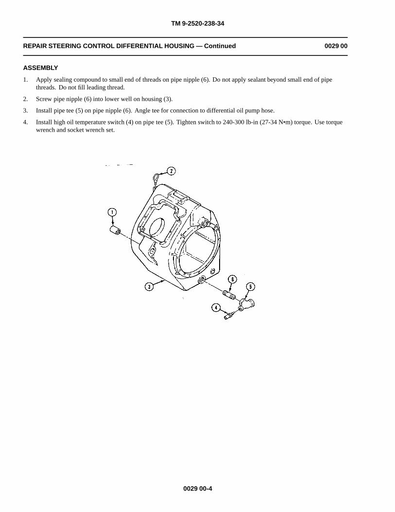
TM 9-2520-238-34
REPAIR STEERING CONTROL DIFFERENTIAL HOUSING — Continued 0029 00
ASSEMBLY
1. Apply sealing compound to small end of threads on pipe nipple (6). Do not apply sealant beyond small end of pipethreads. Do not fill leading thread.
2. Screw pipe nipple (6) into lower well on housing (3).
3. Install pipe tee (5) on pipe nipple (6). Angle tee for connection to differential oil pump hose.
4. Install high oil temperature switch (4) on pipe tee (5). Tighten switch to 240-300 lb-in (27-34 N•m) torque. Use torquewrench and socket wrench set.
0029 00-4

TM 9-2520-238-34
REPAIR STEERING CONTROL DIFFERENTIAL HOUSING — Continued 0029 00
5. Clean threads of lifting eye (1). Apply a light coat of antiseize compound to threads.
6. Install lifting eye (1) in housing (2) by turning lifting eye to the right.
NOTE
If resilient mounts were removed in page 0029 00-2, do Step 7.
7. Install resilient mounts (3). Use remover and replacer.
8. Install new grommet (4) in strainer (5).
9. Place two retainers (6) in housing (2).
10. Place strainer (5) in housing (2). Secure to two retainers (6) with eight washers (7) and cap screws (8). Install newlockwire (9) between screws on each retainer.
11. Install two new needle roller bearings (10) on right side housing (2).
12. Install two new needle roller bearings (10) on left side housing (2).
NOTE
If any alignment dowel pins were removed from housing in page 0029 00-2, do Step 13 and Step14.
13. Install new alignment dowel pin (11) to protrude 21/32 inch (1.68 cm) from housing (2).
14. Install two new alignment dowel pins (12) to protrude 3/8 inch (.97 cm) from housing (2).
WEAR LIMITS
1. See TM 9-214 to check bearings.
0029 00-5

TM 9-2520-238-34
REPAIR STEERING CONTROL DIFFERENTIAL HOUSING — Continued 0029 00
2. Check parts that have reference letters in figure.
3. Check the parts dimensions with chart to determine replacement.
Table 1. STEERING CONTROL DIFFERENTIAL HOUSING WEAR LIMITS
ReferenceLetter
Point of Measurement Size and Fit of New PartsWearLimits
A Inside diameter at bearing surface in housing 5.1179 to 5.1189 (*) (**)
A-B Fit of bearing in housing 0.0016L to 0.002T
* Must be within new parts dimensions.
** Measure only if there is visual indication of bearing turning.
END OF TASK
0029 00-6

TM 9-2520-238-34
CHAPTER 8
DIRECT SUPPORT MAINTENANCE INSTRUCTIONSFOR REPAIR SINGLE DISK PIVOT STEER BRAKE AND HYDRAULIC MASTER BRAKE
CYLINDER
WORK PACKAGE INDEX
Title Sequence No.
REPAIR SINGLE DISK PIVOT STEER BRAKE ASSEMBLY......................................................................................0030 00
REPAIR HYDRAULIC MASTER BRAKE CYLINDER.................................................................................................0031 00


TM 9-2520-238-34
REPAIR SINGLE DISK PIVOT STEER BRAKE ASSEMBLY 0030 00
THIS WORK PACKAGE COVERS:
Disassembly (page 0030 00-2).Cleaning (page 0030 00-5).Assembly (page 0030 00-6).
INITIAL SETUP:
Maintenance Level
Direct Support
Tools and Special Tools
General mechanic’s tool kit (WP 0033 00, Item 37)Arbor press, hand (WP 0033 00, Item 16)Reliner, brake and clutch (WP 0033 00, Item 19)Remover/Replacer tool (WP 0033 00, Item 22)
Materials/Parts
Castile soap (WP 0035 00, Item 2)Grease (WP 0035 00, Item 6)Petrolatum (WP 0035 00, Item 10)Wiping rags (WP 0035 00, Item 17)Preformed packingPreformed packingPreformed packingPreformed packing
Personnel Required
Track Vehicle Repairer
References
See your -20
Equipment Condition
Pivot steer brake assembly removed from carrier (seeyour -20)
0030 00-1
Retaining ring

TM 9-2520-238-34
REPAIR SINGLE DISK PIVOT STEER BRAKE ASSEMBLY — Continued 0030 00
DISASSEMBLY
WARNING
Parts of the brake assembly may be coated with asbestos dust. Breathing this dust can harmpersonnel. Use a filter mask approved for use against asbestos dust. Never use compressed airor dry brush to clean these assemblies. Use an industrial type vacuum cleaner with ahigh-efficiency filter system to remove dust. Use water and a soft bristle brush or cloth toremove dirt or mud.
1. Remove release unit piston (1) with attached brake lining (2) from brake housing (3) using an arbor press. Removepacking (4) from piston. Discard packing.
0030 00-2

TM 9-2520-238-34
REPAIR SINGLE DISK PIVOT STEER BRAKE ASSEMBLY — Continued 0030 00
2. Remove release unit nut (5) with attached parts from housing (3) using remover and replacer tool (6). Remove packing(7) from release unit nut. Discard packing.
NOTE
Turn remover and replacer tool in the clockwise direction.
3. Separate lining (1) from piston (2) using brake and clutch reliner.
0030 00-3

TM 9-2520-238-34
REPAIR SINGLE DISK PIVOT STEER BRAKE ASSEMBLY — Continued 0030 00
NOTE
On some early brake assemblies, the lining is held in place with two rivets and two clips.Remove and discard rivets, if installed.
4. Remove retaining ring (3), spacer (4), and packing (5) from release unit nut (6). Discard retaining ring and packing.
5. Repeat Steps 1 - 4 above for other housing.
NOTE
If vehicle has optional pivot steer brake, do Steps 6 - 9.
6. Remove shoulder screw (7) from brake housing (8). Remove packing (9) from screw. Discard packing.
7. Remove release unit piston (10) with attached brake lining (11) from housing (8) using an arbor press. Remove packing(12) from piston. Discard packing.
8. Remove release unit nut (13) from housing (8) using remover and replacer tool. Remove packing (14) from release unitnut. Discard packing.
NOTE
Turn remover and replacer tool in the clockwise direction.
9. Separate brake lining (11) from piston (10) using brake and clutch reliner.
0030 00-4

TM 9-2520-238-34
REPAIR SINGLE DISK PIVOT STEER BRAKE ASSEMBLY — Continued 0030 00
CLEANING
CLEAN, INSPECT, AND REPAIR
1. Before inspection, repair, or assembly, clean brake housing as described in (WP 0014 00). Clean piston assembly withsolution of clean water and mild castile soap. Rinse in clean water until all traces of soap disappear. Wipe dry using aclean dry cloth.
2. Inspect all parts. Refer to (WP 0014 00) for general inspection and repair procedures.
3. Check brake lining for chips, cracks, or excessive wear. If lining thickness is less than 1/4 inch, replace lining.
0030 00-5

TM 9-2520-238-34
REPAIR SINGLE DISK PIVOT STEER BRAKE ASSEMBLY — Continued 0030 00
ASSEMBLY
NOTEIf optional pivot steer brake was removed, do Steps 1 - 6.
1. Lubricate new packing (1) with grease or petrolatum, and install on release unit nut (2).
2. Install release unit nut (2) in brake housing (3) using remover and replacer tool (4).
NOTETurn remover and replacer tool in the counterclockwise direction.
3. Deform one thread in release unit nut (2) securely in two places a minimum of 45 degrees from holes in unit.
4. Lubricate new packing (5) with grease or petrolatum, and install packing on release unit piston (6).
5. Place brake lining (7) on face of release unit piston (6). Using brake and clutch reliner, install piston in housing (3) untilpiston is flush with outer edge of release unit nut (2).
6. Lubricate new packing (1) with grease or petrolatum, and install packing on shoulder screw (2). Install screw in releaseunit piston (3).
0030 00-6

TM 9-2520-238-34
REPAIR SINGLE DISK PIVOT STEER BRAKE ASSEMBLY — Continued 0030 00
7. Lubricate new packing (4) with grease or petrolatum, and install packing, spacer (5), and new retaining ring (6) in releaseunit nut (7).
8. Lubricate new packing (8) with grease or petrolatum, and install new packing (8) on release unit nut (7).
9. Install release unit nut (7) in brake housing (9) using remover and replacer tool.
NOTETurn remover and replacer tool in the counterclockwise direction.
10. Deform one thread in release unit nut (7) securely in two places a minimum of 45 degrees from holes in unit.
11. Lubricate new packing (10) with grease or petrolatum, and install packing on release unit piston (3).
12. Place brake lining (11) on face of release unit piston (3). Using brake and clutch reliner, install piston with lining inhousing (9) until piston is flush with outer edge of release unit nut (7).
END OF TASK
0030 00-7/8 blank


TM 9-2520-238-34
REPAIR HYDRAULIC MASTER BRAKE CYLINDER 0031 00
THIS WORK PACKAGE COVERS:
Disassembly (page 0031 00-2).Cleaning (page 0031 00-4).Assembly (page 0031 00-5).Set Relief Valve Pressure (page 0031 00-8).
INITIAL SETUP:
Maintenance Level
Direct Support
Tools and Special Tools
General mechanic’s tool kit (WP 0033 00, Item 37)Face wrench socket (WP 0033 00, Item 33)Socket wrench set, 3/8 inch drive (WP 0033 00, Item 34)Torque wrench, 3/8 inch drive, 0-600 lb-in
(WP 0033 00, Item 41)Torque wrench, 1/2 inch drive, 0-300 lb-ft
(WP 0033 00, Item 42)
Materials/Parts
Denatured alcohol (WP 0035 00, Item 3)Hydraulic fluid (FRH) (WP 0035 00, Item 7)Hydraulic parts kit (WP 0035 00, Item 8)Non-electrical wire (WP 0035 00, Item 9)Wiping rags (WP 0035 00, Item 17)
Personnel Required
Track Vehicle Repairer
References
See your -20
Equipment Condition
Hydraulic master brake cylinder removed from carrier(see your -20)
0031 00-1

TM 9-2520-238-34
REPAIR HYDRAULIC MASTER BRAKE CYLINDER — Continued 0031 00
DISASSEMBLY
1. Remove lockwire (1) and instruction plate (2) from vent plug (3). Discard lockwire.
2. Remove protection bellows (4) from master cylinder housing (5). Discard bellows.
3. Remove filler plug (6) with gasket (7) from housing (5). Remove gasket from plug. Discard gasket.
4. Remove vent plug (3) and gasket (8) from relief valve (9). Discard gasket.
5. Remove relief valve (9) from housing (5) using 1/2 inch drive ratchet wrench and face wrench socket (10).
0031 00-2
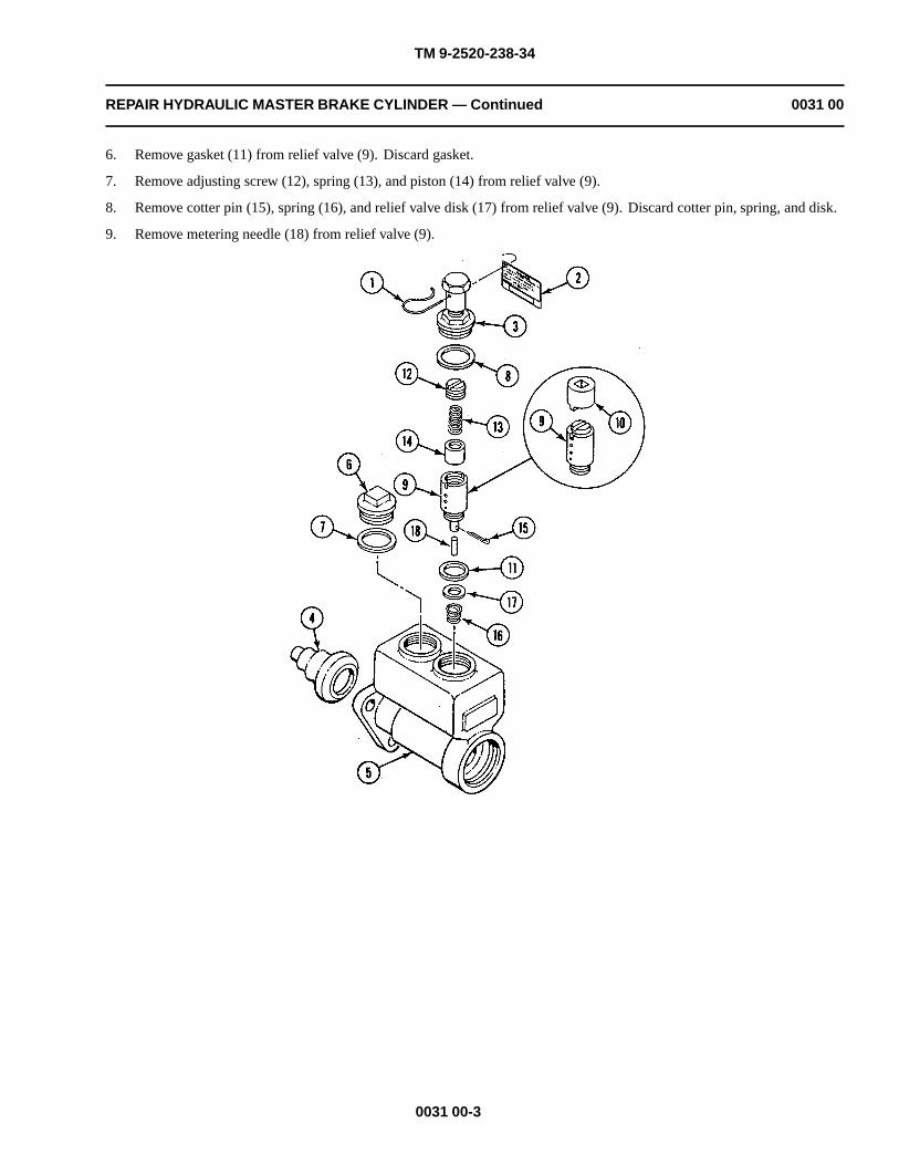
TM 9-2520-238-34
REPAIR HYDRAULIC MASTER BRAKE CYLINDER — Continued 0031 00
6. Remove gasket (11) from relief valve (9). Discard gasket.
7. Remove adjusting screw (12), spring (13), and piston (14) from relief valve (9).
8. Remove cotter pin (15), spring (16), and relief valve disk (17) from relief valve (9). Discard cotter pin, spring, and disk.
9. Remove metering needle (18) from relief valve (9).
0031 00-3

TM 9-2520-238-34
REPAIR HYDRAULIC MASTER BRAKE CYLINDER — Continued 0031 00
CAUTION
Use caution when removing end plug which is under spring pressure.
10. Remove end plug (1), check valve seat (2), check valve (3), spring (4), gasket (5), end plug seal (6), high pressure piston(7), primary cup (8), and gasket (9) from housing (10). Discard check valve seat, check valve, spring, gaskets, end plugseal, and primary cup.
11. Push low pressure piston (11) through housing (10) from pushrod end. Remove spring retainer (12), primary spring (13),and secondary spring (14) from low pressure piston.
12. Separate secondary cup (15) and secondary cup (16) from low pressure piston (11). Discard secondary cups.
CLEANING
CLEANING, INSPECT, AND REPAIR
1. Before inspection, repair, or assembly of master brake cylinder, clean all parts with denatured alcohol. Immediately aftercleaning, dry all parts and coat lightly with same hydraulic fluid as used in brake cylinder.
2. Inspect all parts. Refer to (WP 0014 00) for general inspection and repair procedures.
0031 00-4

TM 9-2520-238-34
REPAIR HYDRAULIC MASTER BRAKE CYLINDER — Continued 0031 00
ASSEMBLY
1. Install new secondary cup (16) and secondary cup (15) on low pressure piston (11).
2. Install low pressure piston (11), primary spring (13), spring retainer (12), secondary spring (14), and new gasket (9) inhousing (10).
3. Install new primary cup (8) on high pressure piston (7).
4. Push low pressure piston (11) forward 1 1/2 inches (3.8 cm) from pushrod end, using screwdriver or similar tool.
5. Maintain spring pressure and insert piston into housing (10) until base of piston sits on gasket (9).
6. Release spring pressure and, at the same time, apply sufficient pressure to base of high pressure piston (7) to preventprimary cup (8) from unseating.
0031 00-5

TM 9-2520-238-34
REPAIR HYDRAULIC MASTER BRAKE CYLINDER — Continued 0031 00
7. Insert screwdriver through opening in housing (1) and apply enough pressure to keep assembled parts in place.
8. Install new end plug seal (2), new gasket (3), new spring, (4) new check valve (5), and new check valve seat (6) inhousing (1). Secure end plug (7). Tighten plug to 80-95 lb-ft (108-129 N•m) torque. Use torque wrench (WP 0033 00,Item 42).
9. Install metering needle (8) in relief valve (9). Secure with new relief valve disk (10), new spring (11), and new cotterpin (12).
10. Install piston (13) and spring (14) in relief valve (9).
11. Install adjusting screw (15) until one screw thread shows in relief valve (9).
12. Install new gasket (16) and relief valve (9) on housing (1). Tighten relief valve to 204-240 lb-in (23-27 N•.m) torque.Use torque wrench (WP 0033 00, Item 41) and face wrench socket (17).
0031 00-6

TM 9-2520-238-34
REPAIR HYDRAULIC MASTER BRAKE CYLINDER — Continued 0031 00
0031 00-7

TM 9-2520-238-34
REPAIR HYDRAULIC MASTER BRAKE CYLINDER — Continued 0031 00
SET RELIEF VALVE PRESSURE
1. Install pressure gauge in output well of housing (1).
2. Fill housing (1) with hydraulic fluid and install new gasket (18) and filler plug (19).
3. Apply pressure at pushrod end and turn adjusting screw (15) until relief pressure is 100-130 psi (69-90 kPa).
4. Remove pressure gage and drain hydraulic fluid from housing (1).
5. Install new gasket (20) and vent plug (21) on relief valve (9).
6. Install new protection bellows (22) on housing (1).
7. Install instruction plate (23) on vent plug (21) with new lockwire (24).
0031 00-8

TM 9-2520-238-34
REPAIR HYDRAULIC MASTER BRAKE CYLINDER — Continued 0031 00
END OF TASK
0031 00-9/10 blank


TM 9-2520-238-34
CHAPTER 9
SUPPORTING INFORMATION
WORK PACKAGE INDEX
Title Sequence No.
REFERENCES...................................................................................................................................................................0032 00
COMMON TOOLS AND SUPPLEMENTS AND SPECIAL TOOLS/FIXTURES LIST...............................................0033 00
FABRICATED TOOLS......................................................................................................................................................0034 00
EXPENDABLE/DURABLE SUPPLIES AND MATERIALS LIST................................................................................0035 00


TM 9-2520-238-34
REFERENCES 0032 00
SCOPE
This work package lists all forms, field manuals, technical manuals and miscellaneous publications to be used by personnel inmaintaining drive train components. The Department of the Army Pamphlets (DA PAM 25–30 series) should for the latestchanges or revisions to references given in this work package and for new publications relating to the material covered in thistechnical manual.
TECHNICAL MANUALS
Organizational Maintenance Manual: Carrier, Personnel, Full Tracked, Armored, M113A2,2350–01–068–4077; Carrier, Command Post, Light, Tracked M577A2,2350–01–068–4089; Carrier Mortar, 107–MM, Self Propelled M106A2,2350–01–069–6931; Carrier, Mortar, 81–MM, Self Propelled M125A2,2350–01–068–0487; Chassis, Gun, Anti-Aircraft Artillery, 20–MM, Self Propelled (M163Weapons System) M741A1, 2350–01–099–8929; Carrier, Smoke Generator, Full Tracked,Armored M1059, 2350–01–203–0188; Combat Vehicle, Anti-Tank, Improved Tow Vehicle,M901A1, 2350–01–103–5641; Carrier, Mortar, 120–MM, Self Propelled M1064,2350–01–338–3116; Carrier, Standardized Integrated Command Post System M1068,2350–01–354–5657....................................................................................................................................TM 9–2350–261-20
Unit Maintenance, Intermediate Direct Support and Intermediate General SupportMaintenance Repair Parts and Special Tools List (Including Depot Maintenance RepairParts and Special Tools List) for Carrier, Personnel, Full Tracked, Armored, M113A2,2350–01–068–4077; Carrier, Command Post, Light, Tracked M577A2,2350–01–068–4089; Carrier Mortar, 107–MM, Self Propelled M106A2,2350–01–069–6931; Carrier, Mortar, 81–MM, Self Propelled M125A2,2350–01–068–0487; Chassis, Gun, Anti-Aircraft Artillery, 20–MM, Self Propelled (M163Weapons System) M741A1, 2350–01–099–8929; Carrier, Smoke Generator, Full Tracked,Armored M1059, 2350–01–203–0188; Combat Vehicle, Anti-Tank, Improved Tow Vehicle,M901A1, 2350–01–103–5641; Carrier, Mortar, 120–MM, Self Propelled M1064,2350–01–338–3116; Carrier, Standardized Integrated Command Post System M1068,2350–01–354–5657...................................................................................................................................TM 9-2350-261-20P
Direct Support and General Support Maintenance: Carrier, Personnel, Full Tracked, Armored,M113A2, 2350–01–068–4077; Carrier, Command Post, Light, Tracked M577A2,2350–01–068–4089; Carrier Mortar, 107–MM, Self Propelled M106A2,2350–01–069–6931; Carrier, Mortar, 81–MM, Self Propelled M125A2,2350–01–068–0487; Chassis, Gun, Anti-Aircraft Artillery, 20–MM, Self Propelled (M163Weapons System) M741A1, 2350–01–099–8929; Carrier, Smoke Generator, Full Tracked,Armored M1059, 2350–01–203–0188; Combat Vehicle, Anti-Tank, Improved Tow Vehicle,M901A1, 2350–01–103–5641; Carrier, Mortar, 120–MM, Self Propelled M1064,2350–01–338–3116; Carrier, Standardized Integrated Command Post System M1068,2350–01–354–5657.....................................................................................................................................TM 9-2350-261-34
Organizational Maintenance: Carrier, Cargo, Tracked, 6–Ton M548, 2320–00–078–4545..........................TM 9-2350–247–20
Direct Support and General Support Maintenance: Carrier, Cargo, Tracked 6–Ton M548,2320–00–078–4545....................................................................................................................................TM 9-2350–247–34
Unit Maintenance: Carrier, Personnel, Full Tracked, Armored M113A2, 2350–01–219–7577;Carrier, Command Post, Light Tracked M577A3, 2350–01–369–6085; Carrier, Anti-Tank(TOW), Full Tracked, Armored M901A3, 2350–01–369–7253; Carrier, Fire SupportPersonnel, Full tracked, Armored M981A3, 2350–01–369–6079; Carrier, SmokeGenerator, Full Tracked M1059A3, 2350–01–369–6083; Carrier Mortar, 120–MM, SelfPropelled M1064A3, 2350–01–369–6082; Carrier, Standardized Integrated Command Post
0032 00-1
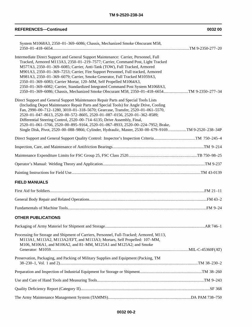
TM 9-2520-238-34
REFERENCES—Continued 0032 00
System M1068A3, 2350–01–369–6086; Chassis, Mechanized Smoke Obscurant M58,2350–01–418–6654....................................................................................................................................TM 9-2350-277–20
Intermediate Direct Support and General Support Maintenance: Carrier, Personnel, FullTracked, Armored M113A3, 2350–01–219–7577; Carrier, Command Post, Light TrackedM577A3, 2350–01–369–6085; Carrier, Anti-Tank (TOW), Full Tracked, ArmoredM901A3, 2350–01–369–7253; Carrier, Fire Support Personnel, Full tracked, ArmoredM981A3, 2350–01–369–6079; Carrier, Smoke Generator, Full Tracked M1059A3,2350–01–369–6083; Carrier Mortar, 120–MM, Self Propelled M1064A3,2350–01–369–6082; Carrier, Standardized Integrated Command Post System M1068A3,2350–01–369–6086; Chassis, Mechanized Smoke Obscurant M58, 2350–01–418–6654........................TM 9-2350–277–34
Direct Support and General Support Maintenance Repair Parts and Special Tools Lists(Including Depot Maintenance Repair Parts and Special Tools) for Angle Drive, CoolingFan, 2990–00–712–1280, 3010–01–318–5670; Gearcase, Transfer, 2520–01–061–5570,2520–01–047–8613, 2520–00–572–8605, 2520–01–087–0156, 2520–01–362–8589;Differential Steering Control, 2520–00–714–6135; Drive Assembly, Final,2520–01–061–5766, 2520–00–895–9164, 2520–01–067–8933, 2520–00–224–7952; Brake,Single Disk, Pivot, 2520–00–088–9866; Cylinder, Hydraulic, Master, 2530–00–679–9169.................TM 9-2520–238–34P
Direct Support and General Support Quality Control: Inspector’s Inspection Criteria........................................TM 750–245–4
Inspection, Care, and Maintenance of Antifriction Bearings.........................................................................................TM 9–214
Maintenance Expenditure Limits for FSC Group 25, FSC Class 2520..................................................................TB 750–98–25
Operator’s Manual: Welding Theory and Application...................................................................................................TM 9-237
Painting Instructions for Field Use.............................................................................................................................TM 43-0139
FIELD MANUALS
First Aid for Soldiers......................................................................................................................................................FM 21–11
General Body Repair and Related Operations.................................................................................................................FM 43–2
Fundamentals of Machine Tools......................................................................................................................................FM 9–24
OTHER PUBLICATIONS
Packaging of Army Materiel for Shipment and Storage................................................................................................AR 746–1
Processing for Storage and Shipment of Carriers, Personnel, Full-Tracked; Armored, M113,M113A1, M113A2, M113A2/EFT, and M113A3; Mortars, Self Propelled: 107–MM,M106, M106A1, and M106A2, and 81–MM, M125A1 and M125A2; and SmokeGenerator: M1059.....................................................................................................................................MIL-C-45360F(AT)
Preservation, Packaging, and Packing of Military Supplies and Equipment (Packing, TM38–230–1, Vol. 1 and 2)......................................................................................................................................TM 38–230–2
Preparation and Inspection of Industrial Equipment for Storage or Shipment............................................................TM 38–260
Use and Care of Hand Tools and Measuring Tools........................................................................................................TM 9–243
Quality Deficiency Report (Category II).............................................................................................................................SF 368
The Army Maintenance Management System (TAMMS)................................................................................DA PAM 738–750
0032 00-2

TM 9-2520-238-34
REFERENCES—Continued 003 00
Verification Inspection of Uneconomically Repairable Major End Items.....................................................................AR 702–8
FORMS
Equipment Component Register.......................................................................................................................DA Form 2408–10
Equipment Control Record.................................................................................................................................DA Form 2408–9
Equipment Daily or Monthly Log.......................................................................................................................DA Form 2408–1
Equipment Modification Record.........................................................................................................................DA Form 2408–5
Equipment Inspection and Maintenance Worksheet...............................................................................................DA Form 2404
Maintenance Request..............................................................................................................................................DA Form 2407
Recommended Changes to Publications and Blank Forms.....................................................................................DA Form 2028
Uncorrected Fault Record.................................................................................................................................DA Form 2408–14
0032 00-3/4 blank

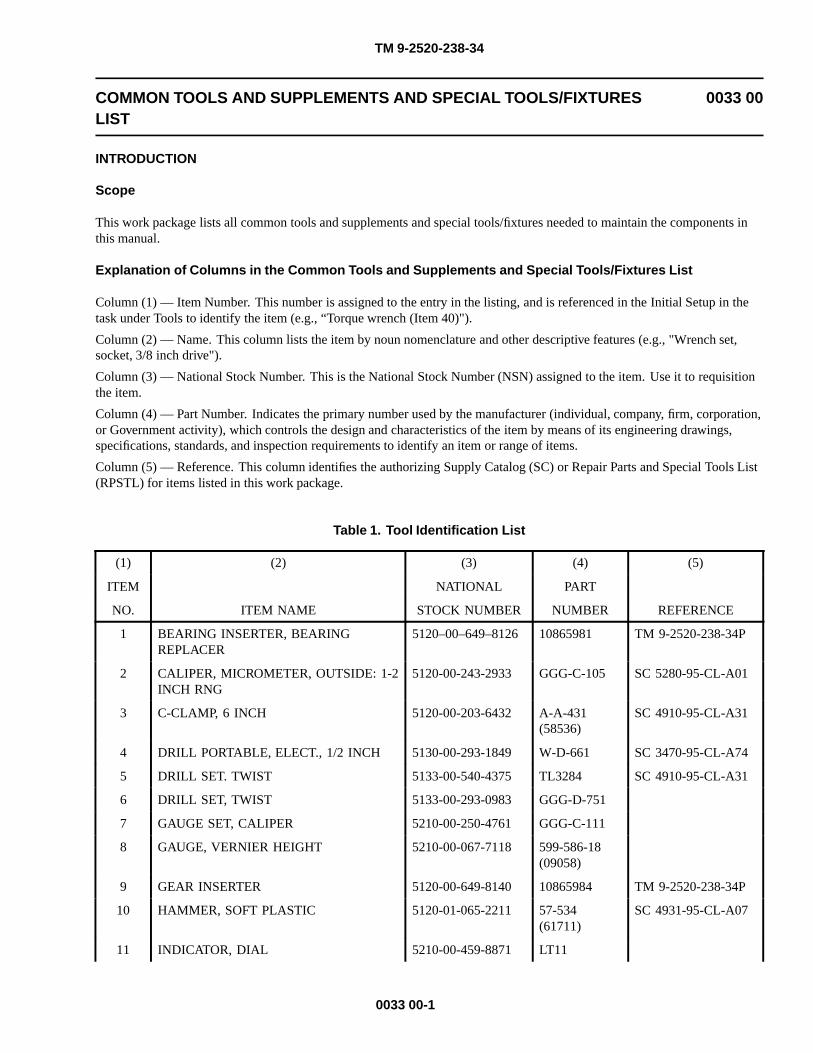
TM 9-2520-238-34
COMMON TOOLS AND SUPPLEMENTS AND SPECIAL TOOLS/FIXTURESLIST
0033 00
INTRODUCTION
Scope
This work package lists all common tools and supplements and special tools/fixtures needed to maintain the components inthis manual.
Explanation of Columns in the Common Tools and Supplements and Special Tools/Fixtures List
Column (1) — Item Number. This number is assigned to the entry in the listing, and is referenced in the Initial Setup in thetask under Tools to identify the item (e.g., “Torque wrench (Item 40)").
Column (2) — Name. This column lists the item by noun nomenclature and other descriptive features (e.g., "Wrench set,socket, 3/8 inch drive").
Column (3) — National Stock Number. This is the National Stock Number (NSN) assigned to the item. Use it to requisitionthe item.
Column (4) — Part Number. Indicates the primary number used by the manufacturer (individual, company, firm, corporation,or Government activity), which controls the design and characteristics of the item by means of its engineering drawings,specifications, standards, and inspection requirements to identify an item or range of items.
Column (5) — Reference. This column identifies the authorizing Supply Catalog (SC) or Repair Parts and Special Tools List(RPSTL) for items listed in this work package.
Table 1. Tool Identification List
(1) (2) (3) (4) (5)
ITEM NATIONAL PART
NO. ITEM NAME STOCK NUMBER NUMBER REFERENCE
1 BEARING INSERTER, BEARINGREPLACER
5120–00–649–8126 10865981 TM 9-2520-238-34P
2 CALIPER, MICROMETER, OUTSIDE: 1-2INCH RNG
5120-00-243-2933 GGG-C-105 SC 5280-95-CL-A01
3 C-CLAMP, 6 INCH 5120-00-203-6432 A-A-431(58536)
SC 4910-95-CL-A31
4 DRILL PORTABLE, ELECT., 1/2 INCH 5130-00-293-1849 W-D-661 SC 3470-95-CL-A74
5 DRILL SET. TWIST 5133-00-540-4375 TL3284 SC 4910-95-CL-A31
6 DRILL SET, TWIST 5133-00-293-0983 GGG-D-751
7 GAUGE SET, CALIPER 5210-00-250-4761 GGG-C-111
8 GAUGE, VERNIER HEIGHT 5210-00-067-7118 599-586-18(09058)
9 GEAR INSERTER 5120-00-649-8140 10865984 TM 9-2520-238-34P
10 HAMMER, SOFT PLASTIC 5120-01-065-2211 57-534(61711)
SC 4931-95-CL-A07
11 INDICATOR, DIAL 5210-00-459-8871 LT11
0033 00-1

TM 9-2520-238-34
COMMON TOOLS AND SUPPLEMENTS AND SPECIAL TOOLS/FIXTURESLIST—Continued
0033 00
(1) (2) (3) (4) (5)
ITEM NATIONAL PART
NO. ITEM NAME STOCK NUMBER NUMBER REFERENCE
12 INDICATOR, DIAL 5210-00-277-8840 MIL-I-18422
13 INDICATOR SET, RANGE DIAL 5210-01-145-5803 CM260
14 PIN, STRAIGHT, HEADLESS (3) 5315-00-834-0118 MS-16556-367 TM 9-2520-238-34P
15 PLIER, WIRE TWISTER 5120-01-112-5031 GA-311C
16 PRESS ARBOR, HAND 3444-00-449-7295 SC 4910-95-CL-A31
17 PULLER KIT, MECHANICAL 5120-00-313-9496 1178 SC 4910-95-CL-A31
18 PULLER KIT, MECHANICAL 5053251-1 TM 9-2520-238-34P
19 RELINER, BRAKE AND CLUTCH 4910-00-173-5310 SC 4910-95-CL-A31
20 REMOVER/REPL, BEARING RETAINER/OUTPUT SHAFT
5120-00-771-7019 10874765 TM 9-2520-238-34P
21 REMOVER/REPLACER, DIFFERENTIALBUSHING
5120-00-740-3346 10943279 TM 9-2520-238-34P
22 REMOVER/REPLACER 5120-00-966-5951 10932469 TM 9-2520-238-34P
23 REMOVER/REPLACER 5120-00-678-2789 10865770 TM 9-2520-238-34P
24 REMOVER/REPLACER 5120-00-678-2798 8763117 TM 9-2520-238-34P
25 REMOVER/REPLACER 5120-00-771-7018 10875326 TM 9-2520-238-34P
26 REMOVER/REPLACER 5120-00-771-7020 10875335 TM 9-2520-238-34P
27 REPLACER, BEARING CUPS 5120-00-776-1864 10886353 TM 9-2520-238-34P
28 SCREW, JACK 5305–00–071–2511 MS90728–14
29 SCREW, JACK 5305-00-226-4832 MS90728–39
30 SCREW, JACK 5305-00-269-3216 MS90728–66
31 SCREWDRIVER BIT SET AND HANDLE 5120-00–832–6224 SC 4931-95-CL-A22
32 SLING, BEAM TYPE 4910-00-646-6893 10942647 TM 9-2520-238-34P
33 SOCKET, WRENCH, FACE (19207) 5120-00-557-8171 11633523 TM 9-2520-238-34P
34 SOCKET WRENCH SET, 3/8 INCHDRIVE
5120-00-322-6231 SC 4910-95-CL-A31
35 SPANNER SOCKET 5052331–1 TM 9-2520-238-34P
36 TOOL, DIFFERENTIAL BACKLASH 5120-00-074-1164 10942815 TM 9-2520-238-34P
37 TOOL KIT, GENERAL MECHANIC’S 5180-00-177-7033 SC 5180-90-N26
38 WRENCH, SOCKET, SCREWDRIVERATTACHMENT
5120-01-367-3462 10E TM 9-2520-238-34P
39 WRENCH, TORQUE, 1/4 INCH DRIVE,2–36 LB-IN
5120-00-021-2041 A-A-2414 SC 4931-95-CL-A22
0033 00-2
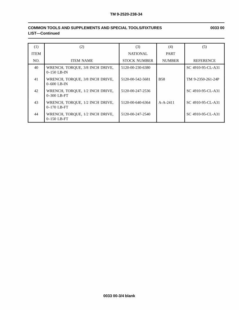
TM 9-2520-238-34
COMMON TOOLS AND SUPPLEMENTS AND SPECIAL TOOLS/FIXTURESLIST—Continued
0033 00
(1) (2) (3) (4) (5)
ITEM NATIONAL PART
NO. ITEM NAME STOCK NUMBER NUMBER REFERENCE
40 WRENCH, TORQUE, 3/8 INCH DRIVE,0–150 LB-IN
5120-00-230-6380 SC 4910-95-CL-A31
41 WRENCH, TORQUE, 3/8 INCH DRIVE,0–600 LB-IN
5120-00-542-5681 B58 TM 9-2350-261-24P
42 WRENCH, TORQUE, 1/2 INCH DRIVE,0–300 LB-FT
5120-00-247-2536 SC 4910-95-CL-A31
43 WRENCH, TORQUE, 1/2 INCH DRIVE,0–170 LB-FT
5120-00-640-6364 A-A-2411 SC 4910-95-CL-A31
44 WRENCH, TORQUE, 1/2 INCH DRIVE,0–150 LB-FT
5120-00-247-2540 SC 4910-95-CL-A31
0033 00-3/4 blank


TM 9-2520-238-34
FABRICATED TOOLS 0034 00
INTRODUCTION
SCOPE
This work package includes instructions to enable direct support and general support personnel to fabricate tools locally.Fabricated tools are not available for issue. Accompanying illustrations below show materials and dimensions required fortool fabrication.
Cooling Fan Right Angle Drive Backlash Adjusting Tool
0034 00-1

TM 9-2520-238-34
FABRICATED TOOLS—Continued 0034 00
Right Angle Drive C Test Stand (top plate)
CHART
A. 4 Places - drill 5/16" holes.
B. 1 Place - Cut 5 1/8" hole.
NOTES:
1. Cut plate of iron 1/4" thick x 10" W x 10" L.
2. Locate holes in plate per diagram. Drill holes per A and B in chart above.
0034 00-2

TM 9-2520-238-34
FABRICATED TOOLS—Continued 0034 00
Right angle Drive C Test Stand (bottom plate)
NOTES:
1. Cut plate of iron 1/4" thick x 10" W x 12" L.
2. Locate holes in plate per diagram. Drill two 5/16" holes.
0034 00-3

TM 9-2520-238-34
FABRICATED TOOLS—Continued 0034 00
Right angle Drive C Test Stand (Side and End View)
NOTES:
1. Cut two plates of iron 1/4" thick x 5" W x 10" L.
2. Weld all plates using any method.
0034 00-4

TM 9-2520-238-34
FABRICATED TOOLS—Continued 0034 00
Right angle Drive C Test Stand (Assembled)
0034 00-5/6 blank

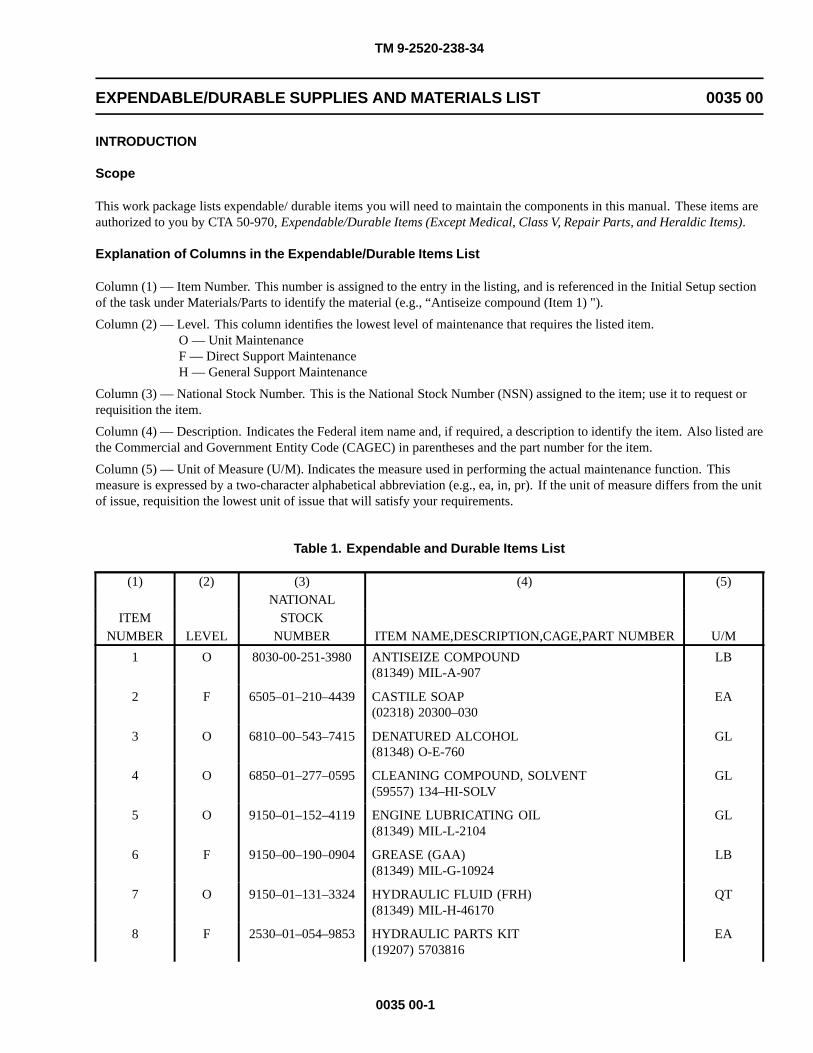
TM 9-2520-238-34
EXPENDABLE/DURABLE SUPPLIES AND MATERIALS LIST 0035 00
INTRODUCTION
Scope
This work package lists expendable/ durable items you will need to maintain the components in this manual. These items areauthorized to you by CTA 50-970, Expendable/Durable Items (Except Medical, Class V, Repair Parts, and Heraldic Items).
Explanation of Columns in the Expendable/Durable Items List
Column (1) — Item Number. This number is assigned to the entry in the listing, and is referenced in the Initial Setup sectionof the task under Materials/Parts to identify the material (e.g., “Antiseize compound (Item 1) ").
Column (2) — Level. This column identifies the lowest level of maintenance that requires the listed item.O — Unit MaintenanceF — Direct Support MaintenanceH — General Support Maintenance
Column (3) — National Stock Number. This is the National Stock Number (NSN) assigned to the item; use it to request orrequisition the item.
Column (4) — Description. Indicates the Federal item name and, if required, a description to identify the item. Also listed arethe Commercial and Government Entity Code (CAGEC) in parentheses and the part number for the item.
Column (5) — Unit of Measure (U/M). Indicates the measure used in performing the actual maintenance function. Thismeasure is expressed by a two-character alphabetical abbreviation (e.g., ea, in, pr). If the unit of measure differs from the unitof issue, requisition the lowest unit of issue that will satisfy your requirements.
Table 1. Expendable and Durable Items List
(1) (2) (3) (4) (5)NATIONAL
ITEM STOCKNUMBER LEVEL NUMBER ITEM NAME,DESCRIPTION,CAGE,PART NUMBER U/M
1 O 8030-00-251-3980 ANTISEIZE COMPOUND(81349) MIL-A-907
LB
2 F 6505–01–210–4439 CASTILE SOAP(02318) 20300–030
EA
3 O 6810–00–543–7415 DENATURED ALCOHOL(81348) O-E-760
GL
4 O 6850–01–277–0595 CLEANING COMPOUND, SOLVENT(59557) 134–HI-SOLV
GL
5 O 9150–01–152–4119 ENGINE LUBRICATING OIL(81349) MIL-L-2104
GL
6 F 9150–00–190–0904 GREASE (GAA)(81349) MIL-G-10924
LB
7 O 9150–01–131–3324 HYDRAULIC FLUID (FRH)(81349) MIL-H-46170
QT
8 F 2530–01–054–9853 HYDRAULIC PARTS KIT(19207) 5703816
EA
0035 00-1

TM 9-2520-238-34
EXPENDABLE/DURABLE SUPPLIES AND MATERIALS LIST—Continued 0035 00
(1) (2) (3) (4) (5)NATIONAL
ITEM STOCKNUMBER LEVEL NUMBER ITEM NAME,DESCRIPTION,CAGE,PART NUMBER U/M
9 O 9505–00–293–4208 NONELECTRICAL WIRE(96906) MS20995C32
LB
10 F 9150–00–250–0933 PETROLATUM(81348) VV-P-236
LB
11 O 8030–00–252–3391 SEALING COMPOUND(81349) MIL-S-45180
OZ
12 O 8030–00–291–1789 SEALING COMPOUND(81349) MIL-S-45180, TY II
PT
13 O 8030–00–656–1426 SEALING COMPOUND(81349) MIL-S-45180, TY III
GL
14 O 8030–01–166–0675 SEALING COMPOUND(05972) 567–47
TB
15 O 8030–01–054–0740 SEALING COMPOUND(05972) 59214
PT
16 O 8030–00–275–8111 SEALING COMPOUND(80244) MIL-S-12158, TY I
OZ
17 O 7920–00–205–1711 WIPING RAG(58536) A-A-2522
LB
0035 00-2
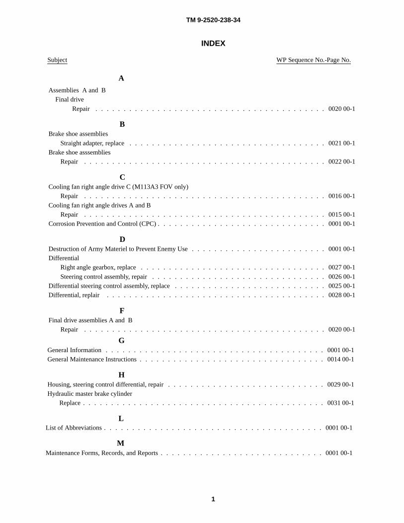
TM 9-2520-238-34
INDEX
Subject WP Sequence No.-Page No.
A
Assemblies A and B
Final drive
Repair . . . . . . . . . . . . . . . . . . . . . . . . . . . . . . . . . . . . . . . . . 0020 00-1
BBrake shoe assemblies
Straight adapter, replace . . . . . . . . . . . . . . . . . . . . . . . . . . . . . . . . . . . 0021 00-1
Brake shoe asssemblies
Repair . . . . . . . . . . . . . . . . . . . . . . . . . . . . . . . . . . . . . . . . . . . 0022 00-1
CCooling fan right angle drive C (M113A3 FOV only)
Repair . . . . . . . . . . . . . . . . . . . . . . . . . . . . . . . . . . . . . . . . . . . 0016 00-1
Cooling fan right angle drives A and B
Repair . . . . . . . . . . . . . . . . . . . . . . . . . . . . . . . . . . . . . . . . . . . 0015 00-1
Corrosion Prevention and Control (CPC) . . . . . . . . . . . . . . . . . . . . . . . . . . . . . . 0001 00-1
DDestruction of Army Materiel to Prevent Enemy Use . . . . . . . . . . . . . . . . . . . . . . . . 0001 00-1
Differential
Right angle gearbox, replace . . . . . . . . . . . . . . . . . . . . . . . . . . . . . . . . . 0027 00-1
Steering control assembly, repair . . . . . . . . . . . . . . . . . . . . . . . . . . . . . . . 0026 00-1
Differential steering control assembly, replace . . . . . . . . . . . . . . . . . . . . . . . . . . . 0025 00-1
Differential, replair . . . . . . . . . . . . . . . . . . . . . . . . . . . . . . . . . . . . . . . 0028 00-1
FFinal drive assemblies A and B
Repair . . . . . . . . . . . . . . . . . . . . . . . . . . . . . . . . . . . . . . . . . . . 0020 00-1
GGeneral Information . . . . . . . . . . . . . . . . . . . . . . . . . . . . . . . . . . . . . . . 0001 00-1
General Maintenance Instructions . . . . . . . . . . . . . . . . . . . . . . . . . . . . . . . . . 0014 00-1
HHousing, steering control differential, repair . . . . . . . . . . . . . . . . . . . . . . . . . . . . 0029 00-1
Hydraulic master brake cylinder
Replace . . . . . . . . . . . . . . . . . . . . . . . . . . . . . . . . . . . . . . . . . . . 0031 00-1
L
1
List of Abbreviations . . . . . . . . . . . . . . . . . . . . . . . . . . . . . . . . . . . . . . . 0001 00-1
MMaintenance Forms, Records, and Reports . . . . . . . . . . . . . . . . . . . . . . . . . . . . . 0001 00-1

TM 9-2520-238-34
INDEX, cont’d
Subject WP Sequence No.-Page No.
NNomenclature Cross-Reference List . . . . . . . . . . . . . . . . . . . . . . . . . . . . . . . . 0001 00-1
OOutput shaft assemblies
Repair . . . . . . . . . . . . . . . . . . . . . . . . . . . . . . . . . . . . . . . . . . . 0024 00-1
Replace . . . . . . . . . . . . . . . . . . . . . . . . . . . . . . . . . . . . . . . . . . . 0023 00-1
PPivot steer brake assembly, single disk, repair . . . . . . . . . . . . . . . . . . . . . . . . . . . 0030 00-1
Preparation for Storage and Shipment . . . . . . . . . . . . . . . . . . . . . . . . . . . . . . . 0001 00-1
Preventive Maintenance Checks and Services (PMCS), Including Lubrication Instructions . . . . . . . 0014 00-1
RReporting of Equipment Improvement Recommendations (EIR) . . . . . . . . . . . . . . . . . . . 0001 00-1
Right angle gearbox, replace . . . . . . . . . . . . . . . . . . . . . . . . . . . . . . . . . . . 0027 00-1
Rjight angle gearbox, replair differential . . . . . . . . . . . . . . . . . . . . . . . . . . . . . . 0028 00-1
SScope . . . . . . . . . . . . . . . . . . . . . . . . . . . . . . . . . . . . . . . . . . . . . . 0001 00-1
Single disk, repair . . . . . . . . . . . . . . . . . . . . . . . . . . . . . . . . . . . . . . . . 0030 00-1
Steering control assembly, repair . . . . . . . . . . . . . . . . . . . . . . . . . . . . . . . . . 0026 00-1
Steering control assembly, replace differential . . . . . . . . . . . . . . . . . . . . . . . . . . . 0025 00-1
Steering control differential, repair . . . . . . . . . . . . . . . . . . . . . . . . . . . . . . . . 0029 00-1
Straight adapter
Brake shoe assemblies, replace . . . . . . . . . . . . . . . . . . . . . . . . . . . . . . . . 0021 00-1
TTransfer gearcase A, B, or C
Replace with service spare transfer gearcase E . . . . . . . . . . . . . . . . . . . . . . . . . 0018 00-1
Transfer gearcase F
Repair . . . . . . . . . . . . . . . . . . . . . . . . . . . . . . . . . . . . . . . . . . . 0019 00-1
Transfer gearcases A, B, and C
Repair . . . . . . . . . . . . . . . . . . . . . . . . . . . . . . . . . . . . . . . . . . . 0017 00-1
2

DISTRIBUTION:
To be distributed in accordance with the initial distribution number (IDN) 371413,requirements for TM 9-2520-238-34.
By Order of the Secretary of the Army:
ERIC K. SHINSEKIGeneral, United States Army
Chief of StaffOfficial
JOEL B. HUDSONAdministrative Assistant to the
Secretary of the Army0105112


RECOMMENDED CHANGES TO PUBLICATIONS ANDBLANK FORMS
For use of this form, see AR 25-30; the proponent agency is OAASA
TELEPHONE EXCHANGE/AUTOVON,PLUS EXTENSION
TYPED NAME, GRADE OR TITLE
PUBLICATION/FORM NUMBER
DATEUse Part II (reverse) for Repair Parts andSpecial Tool Lists (RPSTL) and SupplyCatalogs/Supply Manuals (SC/SM).
FROM: (Activity and location) (Include ZIP Code) TO:
REPLACES DA FORM 2028, 1 DEC 68, WHICH WILL BE USED.
PARA-GRAPH
(Forward to proponent of publication or form) (Include ZIP Code)
PART I - ALL PUBLICATIONS (EXCEPT RPSTL AND SC/SM) AND BLANK FORMS
DATE TITLE
PAGEITEM LINE FIGURENO.
TABLE RECOMMENDED CHANGES AND REASON
* Reference to line numbers within the paragraph or subparagraph.
SIGNATURE
DA FORM 2028, FEB 74 USAPA V3.01

TO: (Forward direct to addressee listed in publication)
TYPED NAME, GRADE OR TITLE
PART III - REMARKS (Any general remarks or recommendations, or suggestions for improvement of publications andblank forms. Additional blank sheets may be used if more space is needed.)
TITLE
FROM: (Activity and location) (Include ZIP Code)
PAGENO.
TELEPHONE EXCHANGE/AUTOVON,PLUS EXTENSION
PUBLICATION NUMBER
COLMNO.
LINENO.
NATIONAL STOCK NUMBER
REFERENCENO.
FIGURE NO.
ITEMNO.
DATE
TOTAL NO.OF MAJOR
ITEMSSUPPORTED
RECOMMENDED ACTION
PART II - REPAIR PARTS AND SPECIAL TOOL LISTS AND SUPPLY CATALOGS/SUPPLY MANUALS
DATE
SIGNATURE
USAPA V3.01
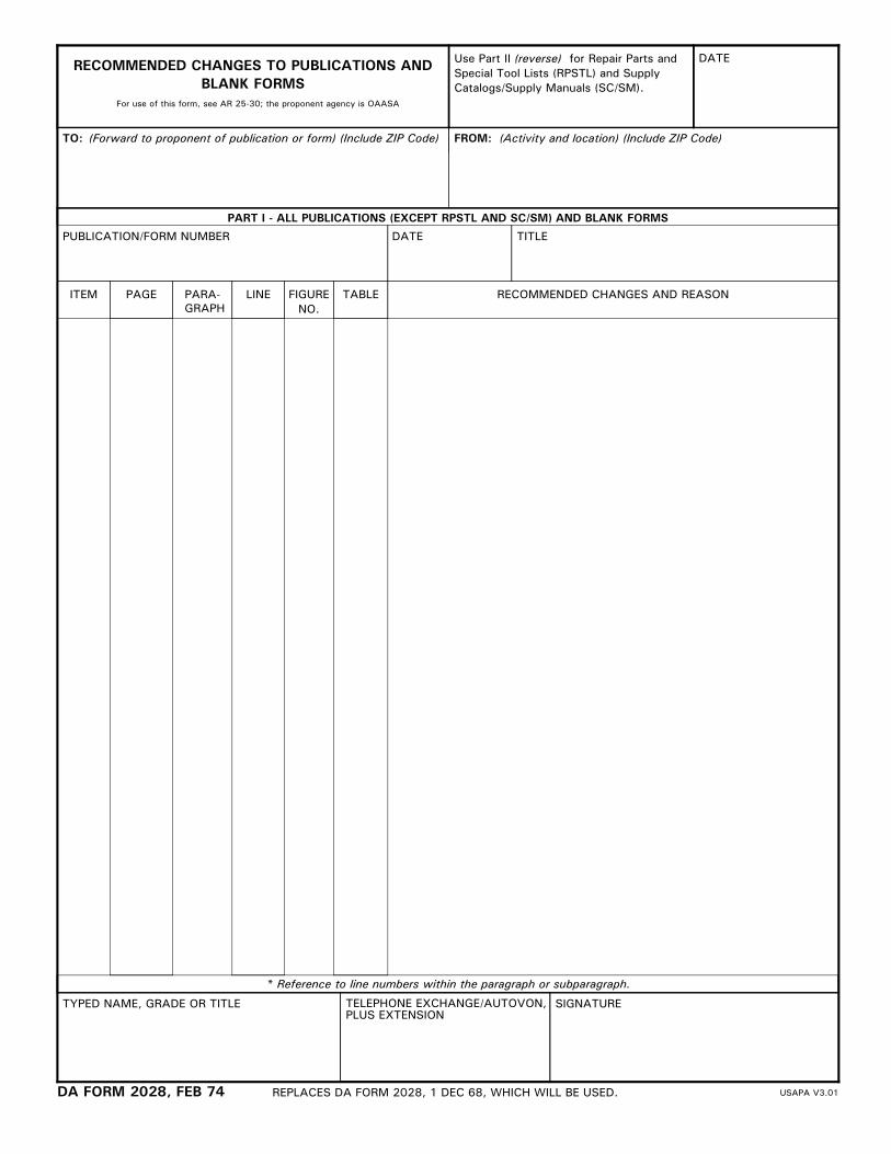

METRIC CONVERSION CHART
APPROXIMATE CONVERSION FACTORS
TO CHANGE TO MULTIPLY BYInches . . . . . . . . . . . . . . . . . . . . . . . . . . . Centimeters . . . . . . . . . . . . . . . . . . . . . 2.540Feet . . . . . . . . . . . . . . . . . . . . . . . . . . . . . Meters . . . . . . . . . . . . . . . . . . . . . . . . . 0.305Yards . . . . . . . . . . . . . . . . . . . . . . . . . . . . Meters . . . . . . . . . . . . . . . . . . . . . . . . . 0.914Miles . . . . . . . . . . . . . . . . . . . . . . . . . . . . Kilometers . . . . . . . . . . . . . . . . . . . . . . 1.609Square Inches . . . . . . . . . . . . . . . . . . . . . Square Centimeters . . . . . . . . . . . . . . . 6.451Square Feet . . . . . . . . . . . . . . . . . . . . . . . Square Meters . . . . . . . . . . . . . . . . . . . 0.093Square Yards . . . . . . . . . . . . . . . . . . . . . . Square Meters . . . . . . . . . . . . . . . . . . . 0.836Square Miles . . . . . . . . . . . . . . . . . . . . . . Square Kilometers . . . . . . . . . . . . . . . . 2.590Acres . . . . . . . . . . . . . . . . . . . . . . . . . . . . Square Hectometers . . . . . . . . . . . . . . 0.405Cubic Feet . . . . . . . . . . . . . . . . . . . . . . . . Cubic Meters . . . . . . . . . . . . . . . . . . . . 0.028Cubic Yards . . . . . . . . . . . . . . . . . . . . . . . Cubic Meters . . . . . . . . . . . . . . . . . . . . 0.765Fluid Ounces . . . . . . . . . . . . . . . . . . . . . . Milliliters . . . . . . . . . . . . . . . . . . . . . . . . 29.573Pints . . . . . . . . . . . . . . . . . . . . . . . . . . . . . Liters . . . . . . . . . . . . . . . . . . . . . . . . . . 0.473Quarts . . . . . . . . . . . . . . . . . . . . . . . . . . . Liters . . . . . . . . . . . . . . . . . . . . . . . . . . 0.946Gallons . . . . . . . . . . . . . . . . . . . . . . . . . . . Liters . . . . . . . . . . . . . . . . . . . . . . . . . . 3.785Ounces . . . . . . . . . . . . . . . . . . . . . . . . . . . Grams . . . . . . . . . . . . . . . . . . . . . . . . . 28.349Pounds . . . . . . . . . . . . . . . . . . . . . . . . . . . Kilograms . . . . . . . . . . . . . . . . . . . . . . . 0.454Short Tons . . . . . . . . . . . . . . . . . . . . . . . . Metric Tons . . . . . . . . . . . . . . . . . . . . . 0.907Pound-Feet . . . . . . . . . . . . . . . . . . . . . . . . Newton-Meters . . . . . . . . . . . . . . . . . . 1.356Pounds per Square Inch . . . . . . . . . . . . . . Kilopascals . . . . . . . . . . . . . . . . . . . . . 6.895Miles per Gallon . . . . . . . . . . . . . . . . . . . . Kilometers per Liter . . . . . . . . . . . . . . . 0.425Miles per Hour . . . . . . . . . . . . . . . . . . . . . Kilometers per Hour . . . . . . . . . . . . . . . 1.609
TO CHANGE TO MULTIPLY BYCentimeters . . . . . . . . . . . . . . . . . . . . . . . Inches . . . . . . . . . . . . . . . . . . . . . . . . . 0.394Meters . . . . . . . . . . . . . . . . . . . . . . . . . . . Feet . . . . . . . . . . . . . . . . . . . . . . . . . . . 3.280Meters . . . . . . . . . . . . . . . . . . . . . . . . . . . Yards . . . . . . . . . . . . . . . . . . . . . . . . . . 1.094Kilometers . . . . . . . . . . . . . . . . . . . . . . . . Miles . . . . . . . . . . . . . . . . . . . . . . . . . . 0.621Square Centimeters . . . . . . . . . . . . . . . . . Square Inches . . . . . . . . . . . . . . . . . . . 0.155Square Meters . . . . . . . . . . . . . . . . . . . . . Square Feet . . . . . . . . . . . . . . . . . . . . . 10.764Square Meters . . . . . . . . . . . . . . . . . . . . . Square Yards . . . . . . . . . . . . . . . . . . . . 1.196Square Kilometers . . . . . . . . . . . . . . . . . . Square Miles . . . . . . . . . . . . . . . . . . . . 0.386Square Hectometers . . . . . . . . . . . . . . . . . Acres . . . . . . . . . . . . . . . . . . . . . . . . . . 2.471Cubic Centimeters . . . . . . . . . . . . . . . . . . Cubic Inches . . . . . . . . . . . . . . . . . . . . 0.060Cubic Meters . . . . . . . . . . . . . . . . . . . . . . Cubic Feet . . . . . . . . . . . . . . . . . . . . . . 35.315Cubic Meters . . . . . . . . . . . . . . . . . . . . . . Cubic Yards . . . . . . . . . . . . . . . . . . . . . 1.308Milliliters . . . . . . . . . . . . . . . . . . . . . . . . . . Fluid Ounces . . . . . . . . . . . . . . . . . . . . 0.034Liters . . . . . . . . . . . . . . . . . . . . . . . . . . . . Pints . . . . . . . . . . . . . . . . . . . . . . . . . . 2.113Liters . . . . . . . . . . . . . . . . . . . . . . . . . . . . Quarts . . . . . . . . . . . . . . . . . . . . . . . . . 1.057Liters . . . . . . . . . . . . . . . . . . . . . . . . . . . . Gallons . . . . . . . . . . . . . . . . . . . . . . . . 0.264Grams . . . . . . . . . . . . . . . . . . . . . . . . . . . Ounces . . . . . . . . . . . . . . . . . . . . . . . . 0.035Kilograms . . . . . . . . . . . . . . . . . . . . . . . . . Pounds . . . . . . . . . . . . . . . . . . . . . . . . 2.205Metric Tons . . . . . . . . . . . . . . . . . . . . . . . . Short Tons . . . . . . . . . . . . . . . . . . . . . . 1.102Newton-Meters . . . . . . . . . . . . . . . . . . . . . Pound-Feet . . . . . . . . . . . . . . . . . . . . . 0.738Kilopascals . . . . . . . . . . . . . . . . . . . . . . . . Pounds per Square Inch . . . . . . . . . . . . 0.145Kilometers per Liter . . . . . . . . . . . . . . . . . . Miles per Gallon . . . . . . . . . . . . . . . . . . 2.354Kilometers per Hour . . . . . . . . . . . . . . . . . Miles per Hour . . . . . . . . . . . . . . . . . . . 0.621
TEMPERATURE CONVERSIONS5/9 (�F − 32) = �C212� Fahrenheit is equivalent to 100� Celsius90� Fahrenheit is equivalent to 32.2� Celsius32� Fahrenheit is equivalent to 0� Celsius9/5 C�
+ 32 = F�

PIN: 028711-000

This fine document...
Was brought to you by me:
Liberated Manuals -- free army and government manuals
Why do I do it? I am tired of sleazy CD-ROM sellers, who take publicly available information, slap “watermarks” and other junk on it, and sell it. Those masters of search engine manipulation make sure that their sites that sell free information, come up first in search engines. They did not create it... They did not even scan it... Why should they get your money? Why are not letting you give those free manuals to your friends?
I am setting this document FREE. This document was made by the US Government and is NOT protected by Copyright. Feel free to share, republish, sell and so on.
I am not asking you for donations, fees or handouts. If you can, please provide a link to liberatedmanuals.com, so that free manuals come up first in search engines:
<A HREF=http://www.liberatedmanuals.com/>Free Military and Government Manuals</A>
– SincerelyIgor Chudovhttp://igor.chudov.com/
– Chicago Machinery Movers


![Noah%2520 valenzuela%2520%2528powerpointslide%2529%5b1%5d[1]](https://img.dokumen.tips/doc/110x75/58a0530e1a28ab5c1c8b485d/noah2520-valenzuela25202528powerpointslide25295b15d1.jpg)


![Mean,%2520 Mode,%2520 Median[1][1]](https://img.dokumen.tips/doc/110x75/558069a5d8b42a925c8b4649/mean2520-mode2520-median11-55848bd8b3f32.jpg)


![Creative%2520 Work%2520 Brief%5 B1%5 D[1]](https://img.dokumen.tips/doc/110x75/54b4cce84a7959a27c8b459b/creative2520-work2520-brief5-b15-d1.jpg)


