Embed Size (px)
Citation preview

Supers
eded
Discipline Engineering Standard – NSW
Category Signalling
Title Specification - Traction Return, Track Insulation and Bonding
Reference Number SCP 02 – (RIC Standard: SC 00 15 00 00 SP)
Document Control
Status Date Prepared Reviewed Endorsed Approved
Standards and Systems
Standards Engineer
GM Infrastructure
Strategy & Performance
Safety Committee
Issue 1 Revision 2
Mar 05
Refer to Reference Number
H Olsen M Owens Refer to minutes
of meeting 12/08/04
Supers
eded
Engineering Standard – NSW Signalling SCP 02 Specification - Traction Return, Track Insulation and Bonding
DISCLAIMER Australian Rail Track Corporation has used its best endeavors to ensure that the content, layout and text of this document is accurate, complete and suitable for its stated purpose. It makes no warranties, express or implied, that compliance with the contents of this document shall be sufficient to ensure safe systems of work or operation. Australian Rail Track Corporation will not be liable to pay compensation in respect of the content or subsequent use of this document for any other purpose than its stated purpose or for any purpose other than that for which it was prepared except where it can be shown to have acted in bad faith or there has been willful default. DOCUMENT APPROVAL The technical content of this document has been approved by the relevant ARTC engineering authority and has also been endorsed by the ARTC Safety Committee. DOCUMENT SUPPLY and CONTROL The Primary Version of this document is the electronic version that is available and accessible on the Australian Rail Track Corporation Internet and Intranet website. It is the document user’s sole responsibility to ensure that copies are checked for currency against the Primary Version prior to its use. COPYRIGHT The information in this document is Copyright protected. Apart from the reproduction without alteration of this document for personal use, non-profit purposes or for any fair dealing as permitted under the Copyright Act 1968, no part of this document may be reproduced, altered, stored or transmitted by any person without the prior written consent of ARTC.
Issue 1 © Australian Rail Track Corporation Revision 2 This document is uncontrolled when printed March 2005 Page 2 of 28

Supers
eded
Engineering Standard – NSW Signalling SCP 02 Specification - Traction Return, Track Insulation and Bonding
About This Standard This Specification sets out the requirements of the Australian Rail Track Corporation for traction return, track circuit insulation and bonding, and electrolysis connections as they relate to non-electrified areas, and electrified areas using 1500 volt DC traction. Specific track circuit operating details will be found in the relevant standards for track circuits. Traction requirements are discussed in terms of “Normal” and “Heavy” traction current areas.
Issue 1 © Australian Rail Track Corporation Revision 2 This document is uncontrolled when printed March 2005 Page 3 of 28

Supers
eded
Engineering Standard – NSW Signalling SCP 02 Specification - Traction Return, Track Insulation and Bonding
Document History Primary Source – RIC Standard SC 00 15 00 00 SP Version 2.0 List of Amendments –
ISSUE DATE CLAUSE DESCRIPTION 1.1 01/09/2004 Reformatting to ARTC Standard 1.2 14/03/2005 Disclaimer Minor editorial change
Footer reformatted
Issue 1 © Australian Rail Track Corporation Revision 2 This document is uncontrolled when printed March 2005 Page 4 of 28

Supers
eded
Engineering Standard – NSW Signalling SCP 02 Specification - Traction Return, Track Insulation and Bonding
Contents
1. Introduction ......................................................................................................... 8 1.1. Purpose of this document ................................................................................. 8 1.2. Definitions ........................................................................................................... 8 1.3. Referenced Standards ....................................................................................... 8 2. Traction Return System and Current Ratings ................................................ 10 2.1. Traction System Ratings ................................................................................. 10 2.2. Electrical Supply .............................................................................................. 10 2.3. Heat Rise Calculations ..................................................................................... 10 2.4. Traction Return Resistance ............................................................................. 11 3. Track Circuits and Traction Return ................................................................ 12 3.1. Track Circuits - General Requirements .......................................................... 12 3.2. Polarity of Track Circuits ................................................................................. 13 3.3. Double Rail Track Circuits ............................................................................... 13 3.3.1. Description ........................................................................................................ 13 3.3.2. Balanced Traction Currents ............................................................................ 13 3.4. Single Rail Track Circuits ................................................................................ 13 3.4.1. Description ........................................................................................................ 13 3.4.2. Longitudinal Voltage Drop in Traction Rail .................................................... 14 3.5. Double Rail 50Hz AC Track Circuits ............................................................... 14 3.5.1. Use and Operation ........................................................................................... 14 3.5.2. Traction Rating of 50Hz Double Rail Track Circuits ...................................... 15 3.5.3. Tie in Bonding of Double Rail Track Circuits ................................................ 15 3.5.4. Connection to Substations and Sectioning Huts .......................................... 15 3.6. Single Rail 50Hz AC Track Circuit ................................................................... 15 3.6.1. Use and Operation ........................................................................................... 15 3.6.2. Traction Current Rating of Single Rail AC Track Circuits ............................ 16 3.6.3. Cross Bonding of Single Rail AC Track Circuits ........................................... 16 3.6.4. Connection to Substations and Sectioning Huts .......................................... 16 3.6.5. Transposition of Traction Rail ......................................................................... 16 3.7. Double Rail Jointless Track Circuits .............................................................. 16 3.7.1. Use and Operation ........................................................................................... 16 3.7.2. Traction Rating of Jointless Track Circuits ................................................... 17 3.7.3. Tie in Bonding on Jointless Track Circuits .................................................... 17 3.7.4. Connection to Substations and Sectioning Huts .......................................... 17 3.8. Double Rail Audio Frequency Track Circuits - Jointed ................................ 17 3.9. Double Rail Impulse Track Circuits ................................................................ 18
Issue 1 © Australian Rail Track Corporation Revision 2 This document is uncontrolled when printed March 2005 Page 5 of 28

Supers
eded
Engineering Standard – NSW Signalling SCP 02 Specification - Traction Return, Track Insulation and Bonding
3.9.1. Use and Operation ........................................................................................... 18 3.9.2. Traction Rating of Impulse Track Circuits ..................................................... 18 3.9.3. Tie in Bonding of Impulse Track Circuits ....................................................... 18 3.9.4. Connection to Substations and Sectioning Huts .......................................... 18 3.10. Single Rail Impulse Track Circuits .................................................................. 18 3.10.1. Use and Operation ......................................................................................... 18 3.10.2. Traction Rating of Single Rail Impulse Track Circuits ............................... 18 3.10.3. Cross Bonding of Single Rail Impulse Track Circuits ................................ 19 3.10.4. Connection to Substations and Sectioning Huts ....................................... 19 4. Traction Supply Interfaces .............................................................................. 20 4.1. Substations ....................................................................................................... 20 4.2. Sectioning Huts ................................................................................................ 20 5. Track Circuit Bonding and Track Insulation................................................... 21 5.1. Bonding at Points and Crossings ................................................................... 21 5.2. Bonding of Single Rail Track Circuits ............................................................ 21 5.3. Bonding of Double Rail Track Circuits ........................................................... 22 5.4. Series Bonding ................................................................................................. 22 5.5. Parallel Bonding ............................................................................................... 22 5.6. Installation of Parallel Bonding Cables .......................................................... 22 5.7. Tie-In Bonding .................................................................................................. 23 5.7.1. Tie-In Bonding Interval .................................................................................... 23 5.7.2. Rating of Tie In Bonding .................................................................................. 23 5.7.3. Track Circuit Integrity Considerations ........................................................... 23 5.8. Cross Bonding of Single Rail Track Circuits ................................................. 24 5.9. Tying-in Non-Track Circuited Tracks .............................................................. 24 5.10. Installation of Tie-in and Cross-Bond Cables ................................................ 24 6. Cables and Busbars ......................................................................................... 25 6.1 Normal Traction Areas...................................................................................... 25 6.1.1 Cables................................................................................................................. 25 6.1.2 Neutral Bus Bar ................................................................................................. 26 6.1.3 Bonding ‘V’ and ‘K’ Crossings and Mechanical Rail Joints .......................... 26 6.2 Heavy Traction Areas........................................................................................ 26 6.2.1 Cables................................................................................................................. 26 6.2.2 Neutral Bus Bar ................................................................................................. 27 6.2.3 Bonding ‘V’ and ‘K’ Crossings and Mechanical Rail Joints .......................... 27 7. Rail Connections .............................................................................................. 28 7.1. Rail Connection Methods ................................................................................ 28 7.2. Connection Lugs .............................................................................................. 28
Issue 1 © Australian Rail Track Corporation Revision 2 This document is uncontrolled when printed March 2005 Page 6 of 28

Supers
eded
Engineering Standard – NSW Signalling SCP 02 Specification - Traction Return, Track Insulation and Bonding
Issue 1 © Australian Rail Track Corporation Revision 2 This document is uncontrolled when printed March 2005 Page 7 of 28
8. Impedance Bonds ............................................................................................ 29 8.1. Traction Rating of Impedance Bonds ............................................................. 29 8.2. AC Impedance of Impedance Bonds .............................................................. 29 8.3. Installation of Impedance Bonds .................................................................... 29 8.3.1. Mounting ........................................................................................................... 29 8.3.2. Connection of Impedance Bonds ................................................................... 29 8.3.3. Side Leads ........................................................................................................ 30 8.3.4. Neutral Connections ........................................................................................ 30 9. Electrolysis Protection ..................................................................................... 31 9.1. Connection of Electrolysis Bond to Track ..................................................... 31 10. Spark Gap Arrestors ......................................................................................... 32

Supers
eded
Engineering Standard – NSW Signalling SCP 02 Specification - Traction Return, Track Insulation and Bonding
1. Introduction
1.1. Purpose of this Document
This document sets out the requirements of the Australian Rail Track Corporation for traction return, track circuit insulation and bonding, and electrolysis connections as they relate to nonelectrified areas, and electrified areas using 1500 volt DC traction. Specific track circuit operating details will be found in the relevant standards for track circuits. Traction requirements are discussed in terms of “Normal” and “Heavy” traction current areas.
1.2. Definitions
In this document, the following definitions of terms shall apply
Principal Signalling Engineer
The person nominated by Australian Rail Track Corporation as Approval Authority for signalling infrastructure standards and designs.
Principal Electrical Engineer
The person nominated by Australian Rail Track Corporation as Approval Authority for traction supply and distribution infrastructure standards and designs.
Signal Engineer
The nominated representative of the contractor responsible for the installation and maintenance of the signalling and traction return infrastructure.
Traction System Engineer
The nominated representative of the contractor responsible for the installation and maintenance of the 1500 volt traction supply and distribution infrastructure.
Hypalon
Generic term for abrasion-resistant tough synthetic rubber insulation material specified for cables installed on ballast. Refers generally to CSP insulating materials, but may include other equivalents.
1.3. Referenced Standards
This standard makes reference to the following Standards National Standards
AS3000 SAA Wiring Rules
ARTC Standards
Signalling Design Principles
Signalling Standard Specification - “Single-Phase Air-Cooled Transformers for Signalling Applications”
Signalling Standard Specification - “Construction of cable route, associated civil works
Issue 1 © Australian Rail Track Corporation Revision 2 This document is uncontrolled when printed March 2005 Page 8 of 28

Supers
eded
Engineering Standard – NSW Signalling SCP 02 Specification - Traction Return, Track Insulation and Bonding
and cable laying”
Signalling Standard Specification - “Cable jointing, terminating and wiring of signalling systems”
Signalling Standard Specification - “Solderless Terminals - Cable Lugs for Signalling Applications”
2. TRACTION RETURN SYSTEM AND CURRENT RATINGS.
2.1. Traction System Ratings
The DC electrified area of the Australian Rail Track Corporation network extends from Port Kembla and Dapto on the Illawarra line; Glenlee in the South; Lithgow in the West; and Newcastle in the North. All of this area is electrified with 1500 volts DC traction supply. In the Sydney metropolitan area the only significant line that is not electrified is the goods line to Botany.
Within the electrified area there are certain steep grades which when traversed by long heavy trains require sustained high traction currents. The designated Heavy Traction areas extend from Rockdale to Thirroul on the Illawarra line, Emu Plains to Lithgow on the Western line and West Ryde to Hamilton Junction on the Northern Line.
Heavy traction equipment must comply with a rating of 2000A per rail continuous capacity, while normal traction must comply with a 1,000A per rail continuous capacity.
2.2. Electrical Supply
The Australian Rail Track Corporation electrified network uses a 1500v DC, single overhead conductor catenary system with traction return via the running rails. The system provided for traction supply from substations connected to line via fault sensing circuit breakers. The catenary is sectioned by air gaps which allow a section to be isolated should a fault occur.
Return current is collected by connecting the substation negative bus bar to the rails, usually by way of impedance bonds.
DC Circuit Breaker (DCCB) settings may be 3,000A to 8,000A depending on the current loading required by train operation.
2.3. Heat Rise Calculations
Standardised designs consider the 6 and 10 minute rating of equipment for the typical gradients and traffic patterns within the section.
Heat rise calculations shall include an analysis of the worst case period of traffic throughout the day. The design must ensure that the operating temperature of the traction return equipment remains within the manufacturers specified limits given the heat rise and cool down characteristics of the equipment for the worst case segment of the timetable.
The recommended combinations of impedance bonds, bonding cables and traction connections are to be found in Sections 5, 6, 7 and 8.
Issue 1 © Australian Rail Track Corporation Revision 2 This document is uncontrolled when printed March 2005 Page 9 of 28

Supers
eded
Engineering Standard – NSW Signalling SCP 02 Specification - Traction Return, Track Insulation and Bonding
2.4. Traction Return Resistance
Track circuits used in conjunction with electric traction must provide an unbroken, lowresistance path for traction current to flow from train to substation, while the maintaining the sectioning of tracks to provide a means of determining the location of a train.
Over the whole route between each Substation and Section Hut, the traction return circuit (ie the rails and bonding) shall have a resistance not greater than the value obtained by assuming that all main line rails are 54 kg/m and all are available for traction return.
The above requirement is based on the requirements of DC Traction protective circuit breaker settings
The DC resistance values of individual rails to be used to calculate traction return resistance are as follows:
45kg/m 0.0438 /1000m
54kg/m 0.0368 /1000m
60kg/m 0.0330 /1000m
The calculation of traction return resistance is the responsibility of the Electrical Engineer, however, the Signal Engineer must use the following guidelines for all designs.
Single track 2 rails at all times
Dual track Mostly 4 rails, but 3 are allowed within interlockings, over points
Multiple tracks Maintain the ratio for dual track unless specific permission is obtained from the Principal Electrical Engineer.
3. TRACK CIRCUITS and TRACTION RETURN
3.1. Track Circuits - General Requirements
DC Electrified Areas
All track circuits within DC electrified areas shall be DC immune.
Track circuits not over points may be high frequency jointless, or pulse type.
AC Electrified Areas
All track circuits within nominated AC electrified areas shall be AC immune.
Track circuits not over points may be high frequency jointless, pulse type or AC immune DC type.
Non-electrified Areas
Issue 1 © Australian Rail Track Corporation Revision 2 This document is uncontrolled when printed March 2005 Page 10 of 28

Supers
eded
Engineering Standard – NSW Signalling SCP 02 Specification - Traction Return, Track Insulation and Bonding
Track circuits not over points may be any approved type.
Track Circuit Equipment
Trackside equipment shall be mounted adjacent to the rail to which it is to be connected.
The track circuit connecting cables to rail shall be duplicated except for tuning unit cables on audio frequency track circuits.
The track circuit connecting cables to rail shall be kept as short as possible.
Cables running between high voltage pulse track circuit units shall be selected to give not more than the total circuit resistance recommended by the manufacturer.
Cables between transmitters and receivers and their matching units and tuning units shall be twisted pair shielded cable constructed in accordance with Signalling Standard Specification – “Cables for Railway Signalling Applications – High Frequency Shielded Track Circuit Cables”.
Impedance bonds shall be provided where a jointless track is terminated at a set of block joints in electrified areas.
Junctions between rails of different sections shall not be used for insulated joints.
Points Track Circuits
Track circuits over motor operated points shall be high voltage pulse type.
Track circuits over mechanically operated facing points shall be high voltage pulse type.
Insulated rail joints within a set of points shall be in the least-used or slower speed route wherever possible.
Track insulated rail joints shall be positioned so that no vehicle can be foul of the points without the points track circuits being occupied.
3.2. Polarity of Track Circuits
On track circuits which use insulated joints for separation, the polarity of adjacent track circuits must be alternated to ensure that the integrity of the insulated rail joint is monitored.
This requirement applies to DC tracks, single and double rail 50Hz Ac tracks, and single and double-rail impulse tracks. It does not apply between tracks of different kinds, but does apply between single and double-rail tracks of the same kind.
The only permitted exceptions are the two parts of a centre-fed track circuit, and interfaces where the feed ends of two similar track circuits abut. In designing a yard area, where the layout renders it impossible to maintain polarity reversal at every insulated joint, the design shall be adjusted to make the like polarities appear at a feed-to-feed interface.
On jointed track circuits which use audio frequency or coding systems to differentiate between adjacent track circuits, the manufacturer’s recommended frequency
Issue 1 © Australian Rail Track Corporation Revision 2 This document is uncontrolled when printed March 2005 Page 11 of 28

Supers
eded
Engineering Standard – NSW Signalling SCP 02 Specification - Traction Return, Track Insulation and Bonding
alternation schemes must be strictly adhered to.
3.3. Double Rail Track Circuits
3.3.1 Description
Double Rail track circuits use both rails for traction return.
3.3.2 Balanced Traction Currents
Impedance bonds rely for their proper operation on traction currents remaining balanced between the rails of the track circuit. It is the responsibility of the Signal Engineer to ensure that the traction return path is properly balanced.
Jointless double rail track circuits only require impedance bonds for tie-in and substation connections, and at interfaces to non -jointless types of track circuit
3.4. Single Rail Track Circuits
3.4.1 Description
Single rail track circuits utilise only one rail for traction current return.
Single rail track circuits are used in station areas and over points where the track circuit length is short and the provision of impedance bonds would be costly.
The disadvantages of single rail track circuits are their limited ability to provide broken rail detection of traction rails, an increase in traction return resistance and a decrease in the integrity of the traction return system due to a reduction in parallel paths available.
Short track circuits used in isolation have little effect on traction return integrity or resistance. Long single-rail track circuits should not be used in electrified areas. Where the use of single rail track circuits over long distances is unavoidable the case must be referred to the ARTC General Manager or nominated Signalling representative for specific approval, as higher traction return resistances adversely affect DCCB settings.
3.4.2 Longitudinal Voltage Drop in Traction Rail
Care must be taken to ensure that the operation of the track circuit can be maintained under all traction load conditions (see below).
When designing single rail track circuits care must be taken that the length of the track circuit does not lead to a DC voltage drop along the signalling rail which will result in signalling equipment failure. The traffic flow, gradient and the location of the nearest substation are significant in determining both the magnitude of the problem and its solution. Table 3.4-1 sets out the expected DC voltage impressed across the relay for typical traction currents.
This DC voltage may be the result of steady state currents, or short term starting current.
Issue 1 © Australian Rail Track Corporation Revision 2 This document is uncontrolled when printed March 2005 Page 12 of 28

Supers
eded
Engineering Standard – NSW Signalling SCP 02 Specification - Traction Return, Track Insulation and Bonding
Current in Traction Rail(A)
1700 3400 5200 6800
Track Circuit Length (m)
Voltage Drop (volts)
50 2.81 5.61 8.58 11.22
75 4.21 8.42 12.87 16.83
150 8.42 16.83 25.74 33.66
200 11.22 22.44 34.32 44.88
250 14.03 23.05 42.90 56.10
300 16.83 33.66 51.48 67.32
Table 3.4-1 DC Voltage drop Impressed across Track Relay on Single Rail Track (Values exceeding permissible limits are shaded)
3.5. Double Rail 50Hz AC Track Circuits
3.5.1 Use and Operation
It has been established that this type of track circuit is sensitive to interference by stray mains frequency currents, resulting in potentially unsafe situations. Special maintenance precautions are required to ensure safe operation of existing installations, and no new tracks of this type shall be installed except in the case of minor changes in the midst of an existing installation.
3.5.2 Traction Rating of 50Hz Double Rail Track Circuits
The rating of double rail A.C. track circuits is determined by the type of impedance bond and dimensions of the bonding cable used.
In Normal traction areas, impedance bond types rated for a minimum 1,000A per rail and suitable for 50Hz track circuits shall be used. (The use of higher rated bonds and cabling is acceptable). Recommended impedance bond types are set out in Section 8.1.
In Heavy traction areas, impedance bond types rated for a minimum 2,000A per rail and suitable for 50Hz track circuits shall be used.
Where the expected current loadings exceed the rating of the 2000 amp per rail impedance bonds, jointless track circuits must be used.
Bonding cable is specified in Section 6.
3.5.3 Tie in Bonding of Double Rail Track Circuits
Tie in bonds shall be provided at intervals of between 1 and 2 kilometres. There shall be no more than one tie-in bond for every other track circuit. The dimensions of
Issue 1 © Australian Rail Track Corporation Revision 2 This document is uncontrolled when printed March 2005 Page 13 of 28

Supers
eded
Engineering Standard – NSW Signalling SCP 02 Specification - Traction Return, Track Insulation and Bonding
cable, type of cable to be used and the methods of connection and laying are detailed in Sections 5.7.
3.5.4 Connection to Substations and Sectioning Huts
Substation and sectioning hut negative bus bars are mandatory tie-in locations. Two impedance bonds of the appropriate rating must be provided on each road for connection to the negative bus bar at the substation. Only one impedance bond for each road is required at sectioning huts.
On double rail 50Hz track circuits the impedance bonds at substations shall be located on either side of an insulated rail joint as the track circuit will not support two impedance bonds located mid track circuit.
Details regarding connections to substations and sectioning huts are to be found in Section 4.
3.6. Single Rail 50Hz AC Track Circuit
3.6.1 Use and Operation
The design of single rail 50Hz track circuits shall include arrangements to limit the maximum level of DC traction current which may be applied to the track relay.
Where the length of track circuit is excessive, the levels of DC being superimposed may result in failure of the relay protecting fuse. The design shall provide sufficient series resistance in the relay circuit to limit DC traction current to a level that will ensure continuous operation of the track circuit equipment. A minimum DC loop resistance of 1 ohm is required in the relay circuit.
The DC voltage drop expected for a given traction current is set out in Section 3.4. This should be used to verify that the measures provided to protect the relay and / or feed units are sufficient. Track circuit length shall be limited such that the longitudinal DC voltage drop under maximum traction conditions does not exceed 20 volts.
Typical maximum single rail AC track circuit lengths are
Normal traction 200m
Heavy traction 100m
However these lengths may need to be reduced in certain cases.
3.6.2 Traction Current Rating of Single Rail AC Track Circuits
Single rail AC track circuits are rated according to length and the protection provided at the relay end of the track circuit is set out in Section 3.3.
3.6.3 Cross Bonding of Single Rail AC Track Circuits
Cross bonding shall be provided at intervals of not more than 200m in accordance with Section 5.8.
Issue 1 © Australian Rail Track Corporation Revision 2 This document is uncontrolled when printed March 2005 Page 14 of 28

Supers
eded
Engineering Standard – NSW Signalling SCP 02 Specification - Traction Return, Track Insulation and Bonding
3.6.4 Connection to Substations and Sectioning Huts
It is preferable that single rail track circuits not be used for these connections unless adjacent siding or refuge tracks provide supporting parallel paths. However, where other requirements dictate their location, connections are to be made between the traction rail and the negative bus by the appropriate cables as set out in Section 4.
3.6.5 Transposition of Traction Rail
Transposition of the traction rail between Up and Down rails of contiguous single rail track circuits is acceptable, but only in exceptional circumstances.
Within any one track circuit, traction return should be arranged to follow a path of continuous rail in the main line or most travelled route, without any transpositions unless absolutely unavoidable.
Where a traction transposition is installed, the number and size of cables shall be the same as are used for impedance bond neutral connections in the same area.
3.7. Double Rail Jointless Track Circuits
3.7.1 Use and Operation
Jointless track circuits are normally separated by means other than mechanically insulated rail joints. They may be used with insulated rail joints and impedance bonds where a sharp cut off is required or when interfacing with another type of track circuit.
Jointless track circuits are suitable for use in Normal and Heavy traction areas as there are no traction sensitive components.
Traction current unbalances between rails are normalised at tying-in points, and by air-cored inductors in some CSEE track circuits.
The maximum length of audio frequency jointless track circuits is not limited by traction current but by the net effect of shunt resistance across the track, including the effects of any impedance bonds used for tying in or connection to substations and sectioning huts.
3.7.2 Traction Rating of Jointless Track Circuits
Jointless track circuits are not in themselves affected by Heavy or Normal traction current situations. However, the rating of impedance bonds used for connection of tie-in bonding or substation and sectioning hut connections or the termination of track circuits at insulated rail joints must be appropriate to the traction level in the section.
3.7.3 Tie in Bonding on Jointless Track Circuits
Tie in Bonding for double rail jointless track circuits is to be provided at 0.8 - 1.6 km intervals and rated according to the traction current rating of the section. There must be at least one clear track circuit between track circuits containing tie-in bonds.
Section 5.7 sets out requirements for installation of tie-in bonding.
Issue 1 © Australian Rail Track Corporation Revision 2 This document is uncontrolled when printed March 2005 Page 15 of 28

Supers
eded
Engineering Standard – NSW Signalling SCP 02 Specification - Traction Return, Track Insulation and Bonding
Tie in bonding is connected between impedance bonds installed on parallel tracks. Impedance bonds used for tying-in shall be rated for the traction rating of the area where they are installed.
The air cored inductor in the tuned loop on CSEE track circuits shall not under any circumstances be used for tying-in.
3.7.4 Connection to Substations and Sectioning Huts
Connection to substations and sectioning huts shall be by impedance bonds of the appropriate rating. The impedance bonds shall be mounted mid track circuit or in any case no closer than 50 metres from the nearest track circuit tuning unit. The connections are specified in Section 4.
Impedance bonds in these situations may be resonated as required. Details in regard to this will be found in the track circuit specification. In general, bonds should be left unresonated (with resonating capacitors open-circuited) unless the track circuit length and ballast conditions make resonation necessary.
3.8. Double Rail Audio Frequency Track Circuits - Jointed
In some circumstances, audio frequency track circuits may be installed as conventional track circuits, separated by insulated rail joints and with impedance bonds to provide traction return continuity. These can consist of conventional audio frequency equipment as used in jointless track circuit arrangements, or be of a particular design intended specifically for jointed operation only.
Traction return and bonding requirements for this arrangement are the same as for double rail 50Hz track circuits.
3.9. Double Rail Impulse Track Circuits
3.9.1 Use and Operation
High voltage impulse track circuits shall be used particularly over points and crossings, and infrequently used tracks where it is most important to guarantee a safe and effective shunting of the track circuit
Double rail impulse track circuits shall be used where it is necessary to maintain a two-rail traction return resistance path.
Double rail impulse track circuit impedance bonds are specialised impulse track circuit equipment and can not be substituted with other types of impedance bonds.
3.9.2 Traction Rating of Impulse Track Circuits
The impedance bonds of the Impulse Track Circuits are rated for Normal (1000A/rail) or Heavy (2000A/rail) current. In Heavy traction cases the Westinghouse 2000P impedance bond shall be used. In Normal traction areas Jeumont Schneider CTI 1400 CT1 or Westinghouse 2000P impedance bonds shall be used.
3.9.3 Tie in Bonding of Impulse Track Circuits
On double rail impulse track circuits the tie-in bonding shall be made at intervals of
Issue 1 © Australian Rail Track Corporation Revision 2 This document is uncontrolled when printed March 2005 Page 16 of 28

Supers
eded
Engineering Standard – NSW Signalling SCP 02 Specification - Traction Return, Track Insulation and Bonding
between 0.8 and 1.6 km with one clear track circuit between the tie-in bonds.
High voltage impulse track circuits are generally not suited to the connection of additional impedance bonds in mid-track, so that tie-in bonding may only occur between the ends of track circuits on adjacent lines.
3.9.4 Connection to Substations and Sectioning Huts
High voltage impulse track circuits are generally not suited to the connection of additional impedance bonds in mid-track. Connections to Substations and Sectioning Huts should be made across the junction of adjacent track circuits specifically sited for that purpose.
3.10. Single Rail Impulse Track Circuits
3.10.1 Use and Operation
Single Rail Impulse Track circuits shall be used in station areas particularly over points, and other areas where contamination is likely to affect the ability of trains to shunt the track circuit. The single rail configuration develops a higher voltage impulse than its double rail counterpart and is therefore slightly more effective in obtaining a shunt under poor conditions.
3.10.2 Traction Rating of Single Rail Impulse Track Circuits
Single Rail Impulse Track circuits can be used in Normal and Heavy traction cases but the length of the track circuit must be limited by the expected DC voltage drop from the maximum traction current calculated for the particular track circuit in question.
Single rail impulse track circuits can withstand a longitudinal DC voltage drop of 30 volts. For Normal traction cases this permits a track circuit length of up to 500m where traction current is light, but as little as 300m in areas close to substations or on grades. In Heavy traction cases the maximum length is 150-200m.
3.10.3 Cross Bonding of Single Rail Impulse Track Circuits
Cross bonding shall be provided at intervals not exceeding 250m in accordance with Section 5.8.
3.10.4 Connection to Substations and Sectioning Huts
Connections to substations and sectioning huts are to be made to the traction rail in accordance with Section 4.
4. TRACTION SUPPLY INTERFACES
Signalling traction return shall be interfaced with the Electrical Engineer’s negative bus bars in accordance with Signalling Design Principle S8, and Clause 6.6 of Signalling Standard Specification – “Cable jointing, terminating and wiring of signalling systems”.
Issue 1 © Australian Rail Track Corporation Revision 2 This document is uncontrolled when printed March 2005 Page 17 of 28

Supers
eded
Engineering Standard – NSW Signalling SCP 02 Specification - Traction Return, Track Insulation and Bonding
4.1. Substations
At substations there shall be two impedance bonds of the appropriate rating (ie. 2 x 2000A/rail impedance bonds for Heavy traction areas or 2 x 1000 A/rail impedance bonds for Normal traction areas) for each track.
Where there is more than one road, the neutrals of the impedance bonds shall be tied together with cables in accordance with Section 5.7 for tie-in bonds. Where the traction system has provided a separate negative busbar for each track this tie-in is not required.
Each impedance bond neutral shall be connected via cables as specified in Section 6.1 or 6.2 as appropriate to the negative bus bar nearest to it.
Where single rail track circuits are in use the traction rail shall be bonded directly to the negative bus bar by cables as specified in Section 6.1 or 6.2 as appropriate, to carry the full rated traction load ie. for 2,000A in the Normal traction case and 4,000A in the Heavy traction case.
The neutral points of the impedance bonds of adjacent track circuits shall be bonded together with cables or busbar in the usual manner, as well as to the substation negative busbar.
In cases where impedance bonds mounted between adjacent tracks would be foul of structure gauge, they may be mounted adjacent to the negative busbars and connected via underline crossings to low-set auxiliary busbars mounted between the tracks.
4.2. Sectioning Huts
The negative bus of the sectioning hut is used to provide a reference point for DCCB operation. It may also be used for automatic earthing of the overhead conductors for maintenance and must be able to carry high fault currents for a short period of time.
At a sectioning hut where there are two or more tracks, these shall be tied-in in accordance with Section 4.2. Where the Traction system’s negative bus connects to each track this tie-in is not required.
The connection to the negative busbar of the sectioning hut shall be similar to that of the substation excepting that only one impedance bond per road is required. Each impedance bond neutral shall be connected via cable as specified in Section 6.1 or 6.2 to the negative bus bar nearest to it by the number of cables specified for neutral connections.
5. TRACK CIRCUIT BONDING and TRACK INSULATION
At points and crossings, insulated rail joints and bonding shall be provided to ensure that track circuits operate effectively, traction return path is maintained, train detection is maintained over all parts of the track circuit, and broken rail protection is maintained to the extent required by Signalling Design Principles S6 and S7.
5.1. Bonding at Points and Crossings
On main lines, bonding of points shall be arranged to provide maximum broken rail detection of both rails in the main line and maximum assurance of train detection in
Issue 1 © Australian Rail Track Corporation Revision 2 This document is uncontrolled when printed March 2005 Page 18 of 28

Supers
eded
Engineering Standard – NSW Signalling SCP 02 Specification - Traction Return, Track Insulation and Bonding
the turnout. On double rail track circuits this shall be achieved by the use of separate receivers on each leg of the turnout. Where this is not practicable, special parallel bonding arrangements for the turnout leg of the track circuit shall be applied. Where a track circuit configuration requires two or more receivers, a minimum of two bonding cables shall be used for the ‘series’ bond connecting each rail of a turnout to its respective rail on the main line.
Elsewhere, single rail track circuits with series/parallel bonding shall be used over points in preference to full parallel bonding, subject to the requirement that three rails out of four be available for traction return.
Where the preferred methods are not practicable, for instance in crossovers between main line tracks, double rail track circuits with full parallel bonding over points may be used. Rails connected by parallel bonding shall not exceed 50 metres in length and the track circuit parameters must conform to the manufacturers recommendations.
Insulation of points and crossings shall be arranged to place insulated joints in the less-used path as far as possible. Bonding shall be arranged to minimise, as far as practicable, the length of all parallel and series bonds.
Track insulation should be designed to use the minimum number of insulated joints needed to comply with all other requirements.
The use of complex, multi-branched track circuits shall be avoided - any track circuit which branches three or more ways should be subdivided into two or more simple track circuits. Due to the diagrammatic nature of track insulation drawings and their inability to accurately reflect the relative positions of items on track, bonding layouts which appear feasible on paper may be complex and unmanageable in the field.
5.2. Bonding of Single Rail Track Circuits
The signalling rail of the single rail track circuit shall be bonded to the same standards as the traction rail with exception of series bonds, which shall not be used or rated for traction return current.
Bonding cable used shall be in accordance with Sections 6.1 or 6.2 as applicable.
Traction rails in single rail track circuits shall be as direct and continuous as possible, including between contiguous track circuits.
Transitions, where insulated joints and bonding are provided to swap the traction rail between the up and down rails of one track circuit, or between contiguous track circuits, are not permitted except subject to prior specific individual approval by the GM ISP or nominated Signalling representative.
5.3. Bonding of Double Rail Track Circuits
For the purpose of improving broken rail detection it is preferable to use additional receivers rather than full parallel bonding. Where parallel bonding is used in double rail track circuits are over points and crossings shall connect both ends of the parallel rails unless multiple receivers are used..
Where multiple receivers are used a minimum of three bonds shall be used to connect each rail of a turnout to its respective rail on the main line. No other parallel bonds are to be used.
Issue 1 © Australian Rail Track Corporation Revision 2 This document is uncontrolled when printed March 2005 Page 19 of 28

Supers
eded
Engineering Standard – NSW Signalling SCP 02 Specification - Traction Return, Track Insulation and Bonding
Where full parallel bonding is used, rails connected by parallel bonding shall not exceed 50 metres in length and the track circuit parameters must conform with the manufacturer’s recommendations.
5.4. Series Bonding
Series bonding shall not be used for traction current return purposes. The sole exception to this requirement is the ‘series’ bond connecting the turnout leg of a set of points with double receivers.
Series bonds shall be duplicated cables of at least 7/0.85mm conductors, installed in buried route between potheads adjacent to each extremity. Connection from pothead to rail shall be by duplicated steel (7/19/0.23 mm) or copper (84/0.3 mm) hypalon cables.
5.5. Parallel Bonding
All parallel bonds shall be at least duplicated at each connection point. Parallel bonds shall be installed at both ends of any parallel bonded section of rail.
Parallel bonding shall be fully visible throughout its length, and not be permitted to become hidden or buried by ballast. Where required by the particular specification parallel bonding may be buried in accordance with Section 5.6.
5.6. Installation of Parallel Bonding Cables
It is essential that bonding cables be installed so that continuity can be checked visually.
All hypalon insulated cables shall be laid directly on the ballast and secured to the sleepers or foot of the rail with suitable clips at not greater than 600mm intervals. Where the hypalon cables run parallel to each other they shall be tied together at not greater than 600mm intervals to form a single unit. Hypalon cables shall never be buried direct nor be permitted to become covered with ballast.
Where the possibility of theft is high, aluminium bonding cables should be used, or cables should be installed with additional protection as described below.
Where there is a particular requirement for mechanical protection of the bonding cables, PVC insulated bonding cable shall be installed, buried in class 12 rigid PVC conduit to within 250mm of rail or impedance bond. The ends of these conduits shall be sealed with concrete or an approved substitute.
When surface run, PVC insulated bonding cables shall be installed in heavy duty, orange coloured flexible PVC conduit laid on the ballast and secured to the sleepers with suitable clips at not greater than 600mm intervals.
5.7. Tie-In Bonding
Tie-in bonding may also be referred to as cross-bonding. It refers to the practice in double rail track circuited areas, of connecting together traction neutral points on adjacent tracks, to increase the parallel return paths available for traction current in both normal and fault conditions, and thereby to minimise the traction return voltage drop.
Issue 1 © Australian Rail Track Corporation Revision 2 This document is uncontrolled when printed March 2005 Page 20 of 28

Supers
eded
Engineering Standard – NSW Signalling SCP 02 Specification - Traction Return, Track Insulation and Bonding
In electrified areas, parallel roads shall be tied together as frequently as practicable subject to the restrictions imposed, to minimise the traction system return resistance and to ensure the availability of a traction return path.
5.7.1 Tie-In Bonding Interval
In open track, tracks shall be tied-in at substations and sectioning huts, and between these at intervals of between 0.8 and 1.6 kilometres. There shall be at least one track circuit clear of tiein bonding between track circuits which have tie-in bonds. The first tie-ins on either side of a substation shall be placed as close as possible within those limits.
Tie in bonds, cable quantities and dimensions are set out in Section 6.1 or 6.2 as applicable.
5.7.2 Rating of Tie In Bonding
Tie in bonding is normally responsible for passing one third to one half of the traction current generated on one road to the parallel road. In fault conditions the tie-in bonding may have to carry the full traction load.
5.7.3 Track Circuit Integrity Considerations
Tie in bonding may, under certain bonding fault conditions, allow circulating signalling currents to interfere with the safe operation of the track circuit. It is for this reason that tie-in bonds must be separated by a clear track circuit.
Where insulated rail joints are in use, the tie-in is made between the impedance bonds at the end of the track circuits. In some cases where the type of track circuit permits it, an additional impedance bond can be fitted mid track circuit for the purpose of tying-in to a parallel track. Jointless track circuits require impedance bonds to be provided mid track circuit.
Tie in bonds shall be as short as possible and tie-in points shall be as near as practicable directly opposite each other. Connections shall be made between the neutral points of impedance bonds on both tracks.
Cables shall be installed as specified in Section 5.10
5.8. Cross Bonding of Single Rail Track Circuits
Cross-bonding refers to the tying-in of traction rails at more frequent intervals in single-rail track circuited areas.
Single rail track circuits provide a reduced traction path, with consequent increased traction return resistance. Parallel traction rails shall be bonded together by appropriately rated traction cables, to form a common traction return ‘grid’. The typical cross bonding interval is 200-250m. Cross-bonding may also include connections to sidings or impedance bond neutral points on adjacent double-rail track circuits.
The cross bonding cables shall be connected to rail as specified in Section 7. The cables shall be surface run over the ballast to allow the continuity of the cable and condition of the insulation to be inspected easily. However, where cable theft is known to be a problem, or the cable run is long the customer may require an under-
Issue 1 © Australian Rail Track Corporation Revision 2 This document is uncontrolled when printed March 2005 Page 21 of 28

Supers
eded
Engineering Standard – NSW Signalling SCP 02 Specification - Traction Return, Track Insulation and Bonding
track crossing to be provided. Installation shall be as specified by Section 5.10.
The cable numbers and dimensions for cross bonding are specified in Sections 6.1 and 6.2 for Normal and Heavy traction respectively.
5.9. Tying-in Non-Track Circuited Tracks
Where tracks are wired for electric traction but not track circuited, their rails should be bonded together and tied in to the adjacent traction return system at their extremities and at intermediate points, depending on the length of the track involved. Traction return bonding shall also be maintained for a short distance past the end of the overhead wiring, at any location where an electric locomotive or train might over-run the end of electrification and render an unbonded return rail ‘live’ at traction supply voltage. This additional traction bonding shall extend for between 20 and 50 metres past the last point of electrified overhead.
Non-electrified, unbonded tracks shall be isolated from rails bonded to the traction return system with insulated joints in both rails, to minimise electrolysis effects.
5.10. Installation of Tie-in and Cross-Bond Cables
Tie-in bond cables shall be run as surface cables in copper or aluminium hypalon, or as V75 PVC cables in underline crossings.
Due to their increased attraction and vulnerability to theft, the preferred installation method for copper tie-in bonds between off-track impedance bonds is in underline crossings.
6. CABLES and BUSBARS
Cables are used to connect impedance bonds and negative bus bars to rail and between neutral points of impedance bonds mounted in-track. They are also used for tie-in bonds, cross bonds, bonding of mechanical rail joints, “out of service” insulated rail joints, and the connection of electrolysis bonds to rail. Bus bars should be used between neutral points of adjacent impedance bonds when they are mounted externally to the track.
Crimp lugs are used to terminate bonding cables for connecting to impedance bonds, neutral busbars and rails.
The current rating of cables and busbars shall be matched to the defined traction current rating of the installation area. Specified crimp lugs are designed to carry the full traction rating.
6.1. Normal Traction Areas
6.1.1 Cables
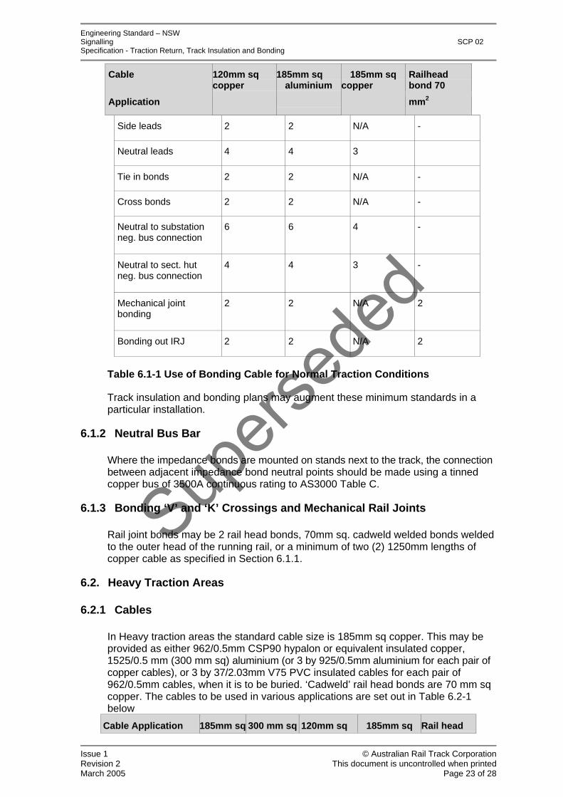
In Normal traction areas the standard cable size is 120mm sq. copper . This may be provided as either 608/0.5mm CSP90 hypalon or equivalent insulated copper, 925/0.5mm hypalon insulated aluminium, or 37/2.03mm PVC insulated copper when it is to be buried. Larger size copper may be used, as well as 70mm sq ‘cadweld’ head bonds. The cables to used in various applications are set out in Table 6.1-1 below
Issue 1 © Australian Rail Track Corporation Revision 2 This document is uncontrolled when printed March 2005 Page 22 of 28
Supers
eded
Engineering Standard – NSW Signalling SCP 02 Specification - Traction Return, Track Insulation and Bonding
Cable 120mm sq copper
185mm sq aluminium
185mm sq copper
Railhead bond 70
Application mm2
Side leads 2 2 N/A -
Neutral leads 4 4 3
Tie in bonds 2 2 N/A -
Cross bonds 2 2 N/A -
Neutral to substation neg. bus connection
6 6 4 -
Neutral to sect. hut neg. bus connection
4 4 3 -
Mechanical joint bonding
2 2 N/A 2
Bonding out IRJ 2 2 N/A 2
Table 6.1-1 Use of Bonding Cable for Normal Traction Conditions
Track insulation and bonding plans may augment these minimum standards in a particular installation.
6.1.2 Neutral Bus Bar
Where the impedance bonds are mounted on stands next to the track, the connection between adjacent impedance bond neutral points should be made using a tinned copper bus of 3500A continuous rating to AS3000 Table C.
6.1.3 Bonding ‘V’ and ‘K’ Crossings and Mechanical Rail Joints
Rail joint bonds may be 2 rail head bonds, 70mm sq. cadweld welded bonds welded to the outer head of the running rail, or a minimum of two (2) 1250mm lengths of copper cable as specified in Section 6.1.1.
6.2. Heavy Traction Areas
6.2.1 Cables
In Heavy traction areas the standard cable size is 185mm sq copper. This may be provided as either 962/0.5mm CSP90 hypalon or equivalent insulated copper, 1525/0.5 mm (300 mm sq) aluminium (or 3 by 925/0.5mm aluminium for each pair of copper cables), or 3 by 37/2.03mm V75 PVC insulated cables for each pair of 962/0.5mm cables, when it is to be buried. ‘Cadweld’ rail head bonds are 70 mm sq copper. The cables to be used in various applications are set out in Table 6.2-1 below
Cable Application 185mm sq 300 mm sq 120mm sq 185mm sq Rail head
Issue 1 © Australian Rail Track Corporation Revision 2 This document is uncontrolled when printed March 2005 Page 23 of 28

Supers
eded
Engineering Standard – NSW Signalling SCP 02 Specification - Traction Return, Track Insulation and Bonding
copper aluminium copper aluminium bond
70 mm sq
Side leads 2 2 3 3 -
Neutral leads 4 4 6 6 -
Tie in bonds 2 2 3 3 -
Cross bonds 2 2 3 3 -
Neutral to substation neg. bus connection
6 6 9 9 -
Neutral to sect. hut neg. bus connection
4 4 6 5 -
Mechanical joint bonding
2 2 2 2 2
Bonding out IRJ 2 2 2 2 2
Table 6.2-1 Use of Bonding Cable for Heavy- Traction Conditions (combinations shown shaded are not preferred)
In certain circumstances a combination of particularly high traction currents, steep grades and frequent traffic may exceed the 2000 amp per rail continuous current rating of Heavy traction areas. Where calculations show that such circumstances may be encountered, an upgraded rating of traction cables (Heavy Class 2) shall be used. Impedance bonds rated for 2000 A/rail may be used in this application.
The cables to be used for extra-Heavy traction (Heavy Class 2) applications are as set out in Table 6.2-2 below.
Cable
Application
85mm sq copper
300mmsq alumin’m
120mmsq copper
185mmsq alumin’m
Rail head bond
70 mm sq
Side leads 4 4 4 4 -
Neutral leads 6 6 8 8 -
Tie in bonds 3 3 4 4 -
Cross bonds 2 2 3 3 -
Neutral to substation neg. bus connection
8 8 12 12 -
Mechanical joint bonding
2 2 2 2 2
Issue 1 © Australian Rail Track Corporation Revision 2 This document is uncontrolled when printed March 2005 Page 24 of 28

Supers
eded
Engineering Standard – NSW Signalling SCP 02 Specification - Traction Return, Track Insulation and Bonding
Bonding out IRJ 2 2 2 2 3
Table 6.2-2 Use of Bonding Cable for Heavy-Class 2 Traction Conditions (combinations shown shaded are not preferred)
Track insulation and bonding plans may augment these minimum standards in special circumstances.
6.2.2 Neutral Bus Bar
Where the impedance bonds are mounted on stands next to the track, the connection between adjacent impedance bond neutral points should be made by a tinned copper bus 3500A continuous rating to AS3000 Table C.
6.2.3 Bonding ‘V’ and ‘K’ Crossings and Mechanical Rail Joints
Rail joint bonds may be 3 rail head bonds, 70mm sq. cadweld welded bonds welded to the outer head of the running rail, or a minimum of two (2) 1250mm lengths of copper cable as specified in Section 6.2.1.
7. Rail Connections
7.1. Rail Connection Methods
For bolted connection to rails, cables shall be terminated in suitable connection lugs as set out in Section 7.2 below.
Rail connections shall be by one of the following three methods
1) Stainless steel stud ‘cadwelded’ to the neutral axis of the web of the rail
Details of the welded stud arrangement are contained in Appendix B of Signalling Standard Specification – “Cable jointing, terminating and wiring of signalling systems”.
2) Copper bush and stainless steel tapered bolt in the neutral axis of the rail
Details of the tapered bolt and copper bush and method of fitting to rail are to be found in Appendix B of Signalling Standard Specification – “Cable jointing, terminating and wiring of signalling systems”.
3) Bifurcated ‘cadwelded’ connection to the outside of the head of the rail.
Two cadweld headbond tails, approximately 160mm long, are joined to the 120 mm sq or 185 mm sq bonding cable by means of a suitably in-line crimp.
(This shall only be used with the specific prior agreement of the responsible per way and signalling maintenance manager/s.)
7.2. Connection Lugs
The details of connection lugs to be used are specified in Signalling Standard Specification - “Cable lugs for railway signalling application”.
Issue 1 © Australian Rail Track Corporation Revision 2 This document is uncontrolled when printed March 2005 Page 25 of 28

Supers
eded
Engineering Standard – NSW Signalling SCP 02 Specification - Traction Return, Track Insulation and Bonding
8. Impedance Bonds
8.1. Traction Rating of Impedance Bonds
There are two ratings of impedance bonds in use in New South Wales. Those for Normal traction are rated at 1,000A per rail continuous current while those for Heavy traction are rated at 2,000A per rail continuous current.
The air cooled Normal traction impedance bonds, Westinghouse MJS, ABW/Macolo 1000 and the GEC Alsthom / Jeumont Schneider CIT 1400 are suitable for 1000A per rail continuous current.
For Heavy traction current areas the Westinghouse 2000R and 2000P, Macolo 2000 and ABB B3 4000 bonds are used.
8.2. AC Impedance of Impedance Bonds
The impedance of the impedance bonds on double rail AC track circuits becomes a limiting factor in setting the length of the track circuit and the maximum shunt value at which the relay will drop.
The older style impedance bonds have an impedance of 0.3 to 0.4 ohms at 50Hz AC which limits the maximum shunt characteristic to 0.15-0.2 ohms.
The air cooled impedance bonds have an impedance of 0.5 ohms at 50Hz AC which limits the maximum shunt characteristic to 0.25 ohms.
The 50Hz impedance of the resonated impedance bonds approaches 2.5 ohms.
8.3. Installation of Impedance Bonds
8.3.1 Mounting
New impedance bonds shall be installed on steel frames mounted outside the track and not between rails. Impedance bonds on contiguous track circuits should be mounted on a common frame.
Mounting shall be in accordance with Signalling Standard Specification – “Construction of cable route, associated civil works and cable laying”.
8.3.2 Connection of Impedance Bonds
The connection of side lead cables to rail shall be in accordance with section 7.1.
The connections of cables to impedance bonds i.e. side leads, neutral leads and tie-in bond leads shall be with crimped cable lugs specified in Section 7.2. Where the type of impedance bond does not permit direct connection of the nominated cables suitable tinned copper adapter plates shall be provided to permit correct termination of the nominated cables and lugs.
Side, neutral and tie-in lead terminations shall be accessible for examination and disconnection with the impedance bond lid or cover in place but shall not be unduly exposed to damage. Where required, cables shall be mechanically supported to reduce the load on the termination point and cable lugs.
Issue 1 © Australian Rail Track Corporation Revision 2 This document is uncontrolled when printed March 2005 Page 26 of 28

Supers
eded
Engineering Standard – NSW Signalling SCP 02 Specification - Traction Return, Track Insulation and Bonding
8.3.3 Side Leads
There shall be a minimum of two side leads from the impedance bond to each rail. Sections 6.1 and 6.2 and the track bonding plans specify the number of side leads required in particular situations.
Side lead connections to rail shall be made as close as practical to the insulated joint. Where the insulated joint has been ‘Thermit’ welded in place, the sideleads shall be connected between the joint and the weld.
To minimise traction return system resistance, all sideleads should be kept as short as possible, while maintaining a tidy and safe installation.
To avoid unreliable operation of the impedance bond due to traction current imbalance, all side leads on any individual impedance bond shall be of equal DC resistance. Generally, this requirement will be satisfied by making all leads of equal length. Where impedance bonds are mounted off track, the upper or farther side lead shall be connected to the near rail, and the lower or nearer side lead shall be connected to the far rail. To facilitate the use of equal side lead lengths, side lead rail connections shall be to the inside face of each rail and the upper side leads on vertical frame-mounted impedance bonds should be terminated to the bond from above. Where welded head-bond connections are used, these shall be connected to the outside of the rail.
8.3.4 Neutral Connections
The neutral connections between adjacent impedance bonds shall preferably consist of a tinned copper busbar as specified in Sections 6.1 and 6.2. This busbar should also be used for terminating any cables for tie-in bonds or connections to substation or sectioning hut busbars.
Where the copper bus connection is not practical, such as with mid track mounted impedance bonds, there shall be a minimum of four neutral leads between the impedance bonds. Section 6.1 and 6.2 and the particular specification may require additional cables and specify cable cross sections. Neutral leads between impedance bonds shall be kept as short and straight as possible.
Where the impedance bond is used to change from a single rail to a double rail track circuit, the total number of neutral leads specified shall be connected to the common (traction) rail of the single rail track circuit.
9. Electrolysis Protection
9.1. Connection of Electrolysis Bond to Track
The traction return system shall include the connection of electrolysis bonds as required.
The Principal Electrical Engineer, with the New South Wales Electrolysis Committee, determines the location at which electrolysis bonding facilities are required, and the type of bonds to be used together with the bond conductance and expected maximum operating voltage and current.
The Signal Engineer is responsible for connecting the electrolysis bond to rail at the specified location.
Issue 1 © Australian Rail Track Corporation Revision 2 This document is uncontrolled when printed March 2005 Page 27 of 28

Supers
eded
Engineering Standard – NSW Signalling SCP 02 Specification - Traction Return, Track Insulation and Bonding
Electrolysis bond connections shall be made to a convenient traction neutral point close to the utility’s electrolysis bond. The electrolysis bond should not be more than 50m from the rail connection. Suitable neutral points are existing impedance bond neutral point connections, SI units (air-cored inductors) on CSEE track circuits, and the traction rail of any single rail track circuit.
Where suitable existing neutral points are not available a Store 54 centre tapped inductor unit may be used on double rail AC and audio frequency track circuits. The Store 54 choke is not suitable for connection to double-rail impulse track circuits. Details of the Store 54 choke are given in Signalling Standard Specification – “Single-phase air-cooled transformers for signalling applications”.
Two cables shall be provided for the connection from the electrolysis bond to the traction neutral point
• One 7/1.70 PVC/PVC/Nylon insulated cable which carries the traction current from the electrolysis bond to the neutral point connection.
• One 7/0.85 PVC/PVC/Nylon insulated cable which is connected to a voltage sensing test terminal at the electrolysis bond.
For double rail track circuits the SI or impedance bond shall be connected in the usual manner to rail. If a Store 54 unit is used it shall be connected to each rail by twin 84/0.3mm copper hypalon insulated cables. These are connected to rail by copper crimp lugs and tapered bolts or 6mm welded studs.
Connection to a single rail track circuit shall be via bootleg riser or junction box and then by twin 84/0.3mm Copper Hypalon insulated cables to the traction rail of the track circuit.
10. Spark Gap Arrestors
Spark gap arrestors are provided on some overhead masts, for example near stations and level crossings, and on all steel or reinforced concrete bridge structures. They are installed at locations where there is a significant probability of persons touching a metallic structure supporting the overhead traction supply, generally to protect against electric shock or electrolysis in the event of an insulator failing and rendering the structure ‘live’ at traction voltage.
The Traction System Engineer provides a PVC sheathed steel bonding cable from the spark gap for connection to the rail by the Signal Engineer. A suitable crimp lug shall be fitted to the steel cable and connection to the rail shall be made by an appropriate method set out in Section 7.
Issue 1 © Australian Rail Track Corporation Revision 2 This document is uncontrolled when printed March 2005 Page 28 of 28