Embed Size (px)
Citation preview

APPLICATION DASH NO. NEXT ASSY USED ON
018 965-1227
TITLE SHEET INDEX
SHEET NO. TITLE SHEET —————————— 1 REVISIONS HISTORY —————————— 2 DOCUMENT —————————— 3
This document is an unpublished work. Copyright 2002, 2009 Honeywell International Inc. All rights reserved.
This document and all information and expression contained herein are the property of Honeywell International Inc., and are provided to the recipient in confidence on a “need to know” basis. Your use of this document is strictly limited to a legitimate business purpose requiring the information contained herein. Your use of this document constitutes acceptance of these terms.
Typed signatures constitute approval. Actual signatures on file at Honeywell in Redmond WA. All sheets of this document are at same revision level.
CONTRACT NO. ------------------
PRECIOUS METAL INDICATOR CODE:
NA Honeywell International Inc. Redmond, Washington 98073-9701
DRAWN Darin Sawich 11 JAN 02 Failure Modes, Effects, and Safety
CHECK Analysis For Installations of
ENGR Darin Sawich 11 JAN 02 The MK XXI Enhanced Ground
MFG Proximity Warning System
QA SIZE CAGE CODE DWG NO. REV.
APVD Gilliland 14 JAN 2002 A 97896 060-4314-018 A
APVD SCALE: NONE SHEET 1 OF 30 HIF-2121/R6 ENGR 2PGT.DOT
PR
OD
UC
TIO
N -
Rel
ease
- 2
7 Ju
l 200
9 09
:17:
23 M
ST
- P
rinte
d on
08
Oct
200
9

PROPRIETARY NOTICE ON TITLE PAGE APPLIES
HIF-2121/R6 CAGE CODE: 97896 SCALE: NONE SIZE: A DWG NO. 060-4134-018 REV: A SHEET 2
REVISIONS
SH REV DESCRIPTION DATE APPROVED
ALL A Revised the document per ECO 68501 to reflect compliance to TSO-C194 and RTCA/DO-309.
Updated section 1.5 to include quantitative analysis related to the probability of HTAWS failures affecting the operation of interfaced devices
Deleted sections 4 and 5 related to Mode 1 functions
Updated reference document lists in section 1.2
Updated table 2-1 to reflect requirements from the MK XXI FHA (060-4314-004)
09-07-24
D. Jones See AeroPDM for additional approvals

PROPRIETARY NOTICE ON TITLE PAGE APPLIES
HIF-2121/R6 CAGE CODE: 97896 SCALE: NONE SIZE: A DWG NO. 060-4134-018 REV: A SHEET 3
Table of Contents 1.0 INTRODUCTION ................................................................................................................................................................ 4
1.1 PURPOSE .............................................................................................................................................................................. 4 1.2 REFERENCE DOCUMENTS .................................................................................................................................................... 4 1.3 PART NUMBERS ................................................................................................................................................................... 5 1.4 MK XXI EGPWS OVERVIEW ............................................................................................................................................. 5 1.5 EGPWC CONSIDERATIONS ................................................................................................................................................. 7
2.0 ANALYSIS OVERVIEW ..................................................................................................................................................... 7
2.1 FAILURE CONDITIONS .......................................................................................................................................................... 7 2.2 ASSUMPTIONS ...................................................................................................................................................................... 8 2.3 LRU FAILURE RATES .......................................................................................................................................................... 8 2.4 DETERMINING LAMBDA λ .................................................................................................................................................... 9
2.4.1 LRU Considerations: Determining the Signal Undetected Failure Rate (UFR) ......................................................... 9 2.4.2 EGPWC Considerations: Determining the Applicability Factor .............................................................................. 10 2.4.3 Exposure Times of Detectable Failures .................................................................................................................... 10
2.5 VARIABLES & EQUATIONS ................................................................................................................................................ 11 2.5.1 Definition of Variables: ............................................................................................................................................ 11 2.5.2 Equations .................................................................................................................................................................. 12
3.0 LOSS OF ALL EGPWS FUNCTIONS ............................................................................................................................. 13
3.1 GPS FAULT ....................................................................................................................................................................... 13 3.2 EGPWC FAULT ................................................................................................................................................................. 13 3.3 PROBABILITY OF THE LOSS OF ALL EGPWS FUNCTIONS ................................................................................................... 13
4.0 FALSE ANNUNCIATION OF A TERRAIN AWARENESS PULL UP CAUTION/WARNING .............................. 14
4.1 POSITION FAULT ................................................................................................................................................................ 15 4.2 TRACK FAULT ................................................................................................................................................................... 15 4.3 GPS ALTITUDE ERROR ...................................................................................................................................................... 16 4.4 ALTITUDE RATE FAULT ..................................................................................................................................................... 16 4.5 EGPWC FAULT ................................................................................................................................................................. 16 4.6 PROBABILITY OF FALSE ANNUNCIATION OF A TERRAIN AWARENESS PULL UP CAUTION/WARNING ................................ 16
5.0 UNANNUNCIATED LOSS OF A TERRAIN AWARENESS PULL UP CAUTION/WARNING ............................. 19
5.1 POSITION FAULT ................................................................................................................................................................ 19 5.2 TRACK FAULT ................................................................................................................................................................... 20 5.3 GROUNDSPEED FAULT ....................................................................................................................................................... 20 5.4 GPS ALTITUDE ERROR ...................................................................................................................................................... 20 5.5 ALTITUDE RATE FAULT ..................................................................................................................................................... 20 5.6 COCKPIT INDICATION FAILURE .......................................................................................................................................... 21 5.7 EGPWC FAULT ................................................................................................................................................................. 22 5.8 PROBABILITY OF THE UNANNUNCIATED LOSS OF A TERRAIN AWARENESS PULL UP CAUTION/WARNING ........................ 22
6.0 HAZARDOUSLY MISLEADING INFORMATION ON THE TERRAIN AWARENESS DISPLAY ...................... 25
6.1 POSITION FAULT ................................................................................................................................................................ 25 6.2 TRACK FAULT ................................................................................................................................................................... 26 6.3 GROUNDSPEED FAULT ....................................................................................................................................................... 26 6.4 GPS ALTITUDE ERROR ...................................................................................................................................................... 26 6.5 ALTITUDE RATE FAULT ..................................................................................................................................................... 26 6.6 DISPLAY RANGE FAULT..................................................................................................................................................... 27 6.7 EGPWC FAULT ................................................................................................................................................................. 27 6.8 PROBABILITY OF HAZARDOUSLY MISLEADING INFORMATION ON THE TERRAIN AWARENESS DISPLAY ........................... 27
7.0 IMPACT OF HTAWS FAILURES ON EXTERNAL DEVICES AND IMPACT ON HTAWS DUE TO EXTERNAL DEVICE FAILURES ............................................................................................................................................... 29
8.0 CONCLUSION ................................................................................................................................................................... 30
PROPRIETARY NOTICE ON TITLE PAGE APPLIES
HIF-2121/R6 CAGE CODE: 97896 SCALE: NONE SIZE: A DWG NO. 060-4134-018 REV: A SHEET 4
1.0 Introduction
1.1 Purpose The analysis provided in this document is a means to show that installations of the MK XXI Enhanced Ground Proximity Warning System (EGPWS) are in compliance with the requirements of FAR 29.1309 paragraphs (b) and (d), FAR 27.1309 paragraphs (b) and (c), and FAA Advisory Circulars AC 29-2C, AC 27-1B and AC 29-XX (draft 4/20/01).
The analysis conducted in this document is an evaluation of EGPWS failure conditions that are identified in, or meet conditions identified in section 27.1309 of FAR Part 27, section 29.1309 of FAR Part 29, AC 27-1B section AC 27.1309.d., AC 29-2C section 29.1309.d. and AC 29-XX (draft 4/20/01) section 10.
1.2 Reference Documents The following documents were utilized in conducting this analysis.
Honeywell Documents:
System Requirements Document (SRD) for the General Aviation Enhanced Ground Proximity Warning Computer (GA-EGPWC)
993-1196-304
Interface Control Document (ICD) for the General Aviation and Helicopter Enhanced Ground Proximity Warning System (GA-EGPWS)/(MK XXI EGPWS)
993-1196-401
Failure Modes Effects and Criticality Analysis For the MK XXI Enhanced Ground Proximity Warning Computer
Product Specification for the MK XXI Helicopter Enhanced Ground Proximity Warning System (EGPWS)
993-1227-600
KGP 560 General Aviation Enhanced Ground Proximity Warning System TSO C151a Class B Pilot’s Guide
Functional Hazard Assessment for Installations of the MK XXI Enhanced Ground Proximity Warning System
006-18254-0000
060-4314-004
FAA Documents:
Federal Aviation Regulations (FAR) Part 29 Airworthiness Standards: Transport Category Rotorcraft
29.1309 Equipment, systems, and installations.
Federal Aviation Regulations (FAR) Part 27 Airworthiness Standards: Normal Category Rotorcraft
27.1309 Equipment, systems, and installations.
Advisory Circular: Certification of Transport Category Rotorcraft AC 29-2C
Advisory Circular: Certification of Normal Category Rotorcraft AC 27-1B
Advisory Circular: Airworthiness Criteria for the Installation Approval of a Helicopter Terrain Awareness and Warning System (HTAWS) for Part 27 and 29 Aircraft
AC 29-XX, draft 4/20/01
Technical Standard Order: Helicopter Terrain Awareness And Warning System
Helicopter Terrain Awareness and Warning System (HTAWS)
TSO-C151b
TSO-C194

PROPRIETARY NOTICE ON TITLE PAGE APPLIES
HIF-2121/R6 CAGE CODE: 97896 SCALE: NONE SIZE: A DWG NO. 060-4134-018 REV: A SHEET 5
Other Documents:
SAE Aerospace Recommended Practice Certification Considerations For Highly-Integrated Or Complex Aircraft Systems
ARP4754
SAE Aerospace Recommended Practice Guidelines And Methods For Conducting the Safety Assessment Process On Civil Airborne Systems And Equipment
ARP4761
U.S. Nuclear Regulatory Commission Fault Tree Handbook
NUREG-0492
Minimum Operational Performance Standards (MOPS) for Helicopter Terrain Awareness and Warning System (HTAWS) Airborne Equipment
DO-309
1.3 Part Numbers This analysis applies to EGPWS installations that use the Honeywell MK XXI EGPWC, Part number 965-1227-xxx.
1.4 MK XXI EGPWS Overview A more complete description of the functions of the MK XXI EGPWS is contained in the referenced Pilot’s Guide. Following is a brief description of the MK XXI EGPWS functions.
The purpose of the Enhanced Ground Proximity Warning System is to help prevent accidents caused by Controlled Flight into Terrain (CFIT). The system achieves this objective by accepting a variety of aircraft parameters as inputs, applying alerting algorithms, and providing the flight crew with aural alert messages and visual annunciations and displays in the event that the boundaries of any alerting envelope are exceeded. Figure 1-1 provides an overall system block diagram.

PROPRIETARY NOTICE ON TITLE PAGE APPLIES
HIF-2121/R6 CAGE CODE: 97896 SCALE: NONE SIZE: A DWG NO. 060-4134-018 REV: A SHEET 6
Figure 1-1: Typical MK XXI EGPWS installation.
MK XXI EGPW C
AUDIO ALERTMESSAGES
AIRCRAFT PARAMETERS
VISUAL ALERTMESSAGES
TERRAIN DISPLAYDATA
GPWSALGORITHMS
TERRAINAWARENESS &
OBSTACLEALERTING AND
DISPLAYALGORITHMS
TERRAINCLEARANCE
FLOORALGORITHMS
W ARNING LAMPW ARNING LAMP
FLIGHT DECKSPEAKERS AND
INTERPHONE
FLIGHT DECKSPEAKERS AND
INTERPHONE
W EATHERRADAR
INDICATOR
W EATHERRADAR
INDICATOR
AIRCRAFTSENSORS
ANDSYSTEMS
AIRCRAFTSENSORS
ANDSYSTEMS
OUTPUT
PROCESSING
INPUT
PROCESSING
AURALCALLOUTS
The system comprises the following groups of components:
• Aircraft sensors and other systems providing input signals
• The MK XXI EGPWC (Enhanced Ground Proximity Warning Computer)
• Flight deck audio systems (speakers and interphone)
• Warning lamp
• Weather Radar Indicator for display of terrain.
• Switching relay for switching display inputs from weather display to terrain display.
The system is designed to be fully compatible with normal operations of rotary wing aircraft. Unwanted alerts will be very rare if the flight crew maintains situational awareness with respect to the terrain.
The MK XXI EGPWC is a single Line Replaceable Unit (LRU) with several integrated, main alerting functional areas. The functional areas are:
• Terrain, Peaks and Obstacle Awareness alerts as well as optional display of this information.
• Helicopter Altitude Monitoring
• Helicopter Excessive Bank-angle Callouts
In addition to the main alerting functions, the EGPWC also performs the following auxiliary functions:
• Input signal processing (including filtering and signal monitoring).

PROPRIETARY NOTICE ON TITLE PAGE APPLIES
HIF-2121/R6 CAGE CODE: 97896 SCALE: NONE SIZE: A DWG NO. 060-4134-018 REV: A SHEET 7
• Alert output processing (including alert prioritization, voice message synthesis, audio output, and display and alert lamp driver control).
• Built-In Test and Monitoring including a cockpit-activated Self-Test.
• PCMCIA interface for uploading software and databases.
• Front panel maintenance test connector for system checkout and troubleshooting.
1.5 EGPWC Considerations The 965-1227-xxx series part number MK XXI EGPWC includes an internal GPS-PXPRESS card and is intended for use on helicopter aircraft that provide a limited mixture of analog and digital interfaces. The terrain database included with the EGPWC is regional (as opposed to global).
In accordance with TSO-C151b, TSO-C194 and AC 29-XX, draft 4/20/01, the MK XXI EGPWC is classified as Class B TAWS or HTAWS equipment.
2.0 Analysis Overview
2.1 Failure Conditions System failure conditions that have been identified as “…conditions which would reduce the capability of the rotorcraft or the ability of the crew to cope with adverse operating conditions…” in accordance with FAR Part 29, section 29.1309; or are addressed by FAR Part 27 section 27.1309 or AC 29-XX (draft 4/20/01) are evaluated in this analysis. There are no failure conditions of the EGPWS that meet the criteria of “…preventing the continued safe flight and landing of the rotorcraft…” FAR Part 29 section 29.1309; or the criticality categories Catastrophic or Hazardous/Severe-Major as defined in AC 27-1B section AC 27.1309 and AC 29-2C section AC 29.1309. Table 2-1 identifies the failure conditions that are evaluated, along with the Criticality Level and Probability Classification assigned as defined in AC 27-1B and AC 29-2C. The failure conditions and criticality levels are compiled from major failures identified in the functional hazard assessment (060-4314-004).
Some analyses combine similar failure conditions
• Unannunciated Loss of Warning analysis includes both (1) loss of warning function and (2) loss of caution function
• False Annunciation of both TA Warning and TA cautions
• Hazardously Misleading Data on the Terrain Display combines corrupted display/valid position display and display of terrain not in the current position. The analysis is valid for both standard terrain displays and peaks terrain displays.
• The analysis related to HTAWS failures corrupting external devices or external device failures corrupting HTAWS combines 2 failure conditions from the FHA (e.g. (1) HTAWS failure affects the integrity of the interface to an external device (2) Failure of a device interfaced to HTAWS affects the integrity of HTAWS functions (other than those using data from the device).
Table 2-1: Criticality Levels and Probability Classifications of evaluated failure conditions
Failure Conditions Analyzed in this Report Criticality Level Probability Classification
Loss of all EGPWS Functions Minor Probable
False Annunciation of Terrain Awareness “Pull Up” Warning/Caution Major Remote Unannunciated Loss of the Terrain Awareness “Pull Up” Warning/Caution Major Remote
Hazardously Misleading Information on the Terrain Awareness Display Major Remote HTAWS failure corrupts external device or external device failure corrupts HTAWS Major Remote

PROPRIETARY NOTICE ON TITLE PAGE APPLIES
HIF-2121/R6 CAGE CODE: 97896 SCALE: NONE SIZE: A DWG NO. 060-4134-018 REV: A SHEET 8
Unlike the other failure conditions in this evaluation, where undetected or latent signal failures are the contributing events to the failure condition, “Loss of all EGPWS Functions” involves all failures to the system components that contribute to this condition. Therefore the LRU failure rates are used in this evaluation.
A False Annunciation of a caution/warning results when any EGPWS indicator in the cockpit, either a Warning lamp, speaker, or Terrain Awareness Display, indicates a warning condition while the design-warning thresholds of the EGPWC have not been exceeded.
There are two conditions for an unannunciated loss of a warning or caution. One is when none of the EGPWS indicators in the cockpit (Warning lamp, speaker, and Terrain Awareness Display) indicate a warning condition while the warning thresholds of the EGPWC have been exceeded. The second condition is when there is no indication in the cockpit of a failure of the EGPWS functions.
AC 29-XX, draft 4/20/01 defines Hazardously Misleading Information (HMI) as: “An incorrect depiction of the terrain or obstacle threat relative to the aircraft during an alert condition (excluding source data)”.
2.2 Assumptions The intent of this analysis is to be applicable to all possible MK XXI EGPWS installations. To accomplish this, defined MK XXI EGPWS configurations are not used. Instead, for each failure condition the worst-case failure rates, MK XXI EGPWS configuration(s), and aircraft operating scenarios are used.
For example, this analysis assumes an analog Altitude Encoder Air Data input and Terrain Display on a Weather Radar PPI. If the aircraft installation being analyzed includes a digital Air Data input and no Terrain Display, then this analysis will still be applicable to the installation, since the installation will be better than the “worst-case installation” analyzed in this document.
This analysis uses the worst failure data known to Honeywell from the LRUs supplying the MK XXI EGPWC. In an actual installation being performed, if an LRU supplying the MK XXI EGPWC has a worse failure rate than that presented within this analysis the installer/certifying team must evaluate the impact of the LRU failure rate on the overall reliability of the MK XII EGPWS to insure that the installation satisfies the applicable regulations.
The following listed assumptions are consistent throughout the analysis:
• Average Flight duration: 1 hour.
• 7 flights per day.
• 1 Warning lamp in the cockpit.
• 1 HTAWS INOP lamp in the cockpit.
• 1 display and relay (TA/Wx Relay) for the Terrain/Obstacle Awareness function.
• 1 dedicated HTAWS speaker in the cockpit.
• 1 GPS external to the MK XXI EGPWC.
• 1 HTAWS Self-Test is performed daily.
• Where possible, the average Probability of Failure per flight hour is calculated.
• Basic failure events with a failure rate less than 10-9 are not evaluated.
2.3 LRU Failure Rates To determine the worst-case failure rates of the LRUs that supply signals to the MK XXI EGPWC, Honeywell has evaluated field failure rate data provided by customers who have installed the EGPWS or GPWS on their aircraft. From this field data the worst-case failure rates are used. Table 2-2 lists the failure rates and Undetected Failure Rates (UFR) used in this analysis.

PROPRIETARY NOTICE ON TITLE PAGE APPLIES
HIF-2121/R6 CAGE CODE: 97896 SCALE: NONE SIZE: A DWG NO. 060-4134-018 REV: A SHEET 9
The Undetected Failure Rate (UFR) is an estimate of the number of failures of the LRU that the LRU’s BIT (Built-In-Test) does not detect. The following assumptions for BIT coverage are used:
Analog LRU: 90% of the failures are detected by BIT.
Digital LRU: 95% of the failures are detected by BIT.
Table 2-2: LRU failure rates for aircraft system components.
LRU Failure Rate (failures per hour)
Undetected Failure Rate (UFR)
Digital (5%) Analog (10%)
Air Data Computer (ADC) 205 x 10-6 20.5 x 10⁻⁶
Global Positioning System (GPS) 85.7 x 10⁻⁶ 4.285 x 10⁻⁶
Cockpit lamps 4.455 x 10⁻⁶ 4.455 x 10⁻⁶
Cockpit speaker 2.1 x 10⁻⁶ 2.1 x 10⁻⁶
Discrete switches 6.37 x 10⁻⁶ 0.637 x 10⁻⁶
TA/Wx Relay 28 x 10-6 2.8 x 10⁻⁶
TA Display - Weather Radar PPI 227.1 x 10⁻⁶ 11.355 x 10⁻⁶
2.4 Determining Lambda λ Lambda (λ) is the failure rate of a signal considering only undetected failures that contribute to the occurrence of the failure condition being analyzed. To determine the value of λ, the UFR of the LRUs are separated into a UFR for each signal that the LRU provides in the EGPWS. Not all of the undetected failures of a signal will contribute to the failure condition being analyzed. For each failure condition the undetected failures of a signal are evaluated for the impact they have on the algorithms used by the EGPWS. An Applicability Factor is determined for each signal; this factor represents a conservative estimate of the fraction of undetected failures of the signal that contribute to the failure condition being analyzed. The Applicability Factor is applied to the UFR of the signal to create the value of λ for the signal.
2.4.1 LRU Considerations: Determining the Signal Undetected Failure Rate (UFR) If the LRU only produces one signal that is used by the EGPWS, the UFR of the LRU is used as the UFR of the signal. If the LRU produces multiple signals that are used by the EGPWS, assume an even distribution of the UFR across these signals, i.e. divide the UFR by the number of signals the LRU provides to the EGPWC. This approach serves 2 purposes 1) it reduces the amount of work done in evaluating the failures of the systems that provide the signals to the EGPWC, and 2) it errors on the conservative side. To evaluate the worst-case situation, configurations with the minimum number of signals from each LRU were used to calculate the UFR of the signals. Table 2-3 identifies the UFR of each signal used in this analysis.

PROPRIETARY NOTICE ON TITLE PAGE APPLIES
HIF-2121/R6 CAGE CODE: 97896 SCALE: NONE SIZE: A DWG NO. 060-4134-018 REV: A SHEET 10
Table 2-3: MK XXI EGPWS signal undetected failure rates.
LRU Minimum number of signals provided to the MK XXI EGPWC
Signal undetected failure rates
Air Data Computer (ADC) 2 10.25 x 10⁻⁶
Global Positioning System (GPS) 12 0.357 x 10⁻⁶
Cockpit lamps 1 (each lamp) 4.455 x 10⁻⁶
Cockpit speaker 1 2.1 x 10⁻⁶
Discrete switches 1 (each switch) 0.637 x 10⁻⁶
TA/Wx Relay 1 2.8 x 10⁻⁶
TA Display - Weather Radar PPI 1 11.355 x 10⁻⁶
2.4.2 EGPWC Considerations: Determining the Applicability Factor The Applicability Factor is an adjustment to the signal UFR to take into account the failure mode of the signal and the impact the signal has within the algorithms used by the EGPWC. The algorithms in the EGPWC combine many signal values together and very few signals have a dominant role in the final solution. Some signals have such a limited impact that even a worst-case failure cannot cause the failure condition. In this analysis only single point failures are evaluated, therefore signals that by themselves cannot produce the failure condition under consideration are not included.
An undetected signal failure is defined as; the signal indicates that it is valid but the value of the signal is erroneous. There are 3 failure modes possible for each undetected signal failure.
1. The signal indicates a value greater than the actual value.
2. The signal indicates a value less than the actual value.
3. Degraded condition, which includes all other failure modes not covered by 1 and 2.
Only the first 2 failure modes are considered for their effect on the failure condition being evaluated. Only one of these two conditions can contribute to the failure condition being evaluated. In this analysis we assume the signal UFR is an even distribution of these 2 signal failure modes.
The GPW functions have been in service for over 20 years. During this time the algorithms for these functions have under gone many changes, corrections, and adjustments to reduce nuisance alerts and missed alerts due to inconsistencies in the signal inputs. This has resulted in EGPWC functions that are very tolerant of input signal errors and have robust reasonableness testing. The magnitude of the error must be considered. It cannot be so large as to fail a reasonableness test, but it must be large enough to overcome the built-in signal error tolerance of the EGPWC. In the EGPWC algorithms a signal can be used to establish the alerting curve or threshold, or it may be the parameter that is being evaluated. In general, if the signal is used in establishing the alerting curve, an error in the signal will cause the EGPWS to become more sensitive, moves the curve to the left, or less sensitive, moves the curve to the right. If the signal is the parameter being evaluated it will have a greater effect on causing the failure condition.
The Probability of Failure per flight (Pf) for the MK XXI EGPWC is derived from the referenced Failure Modes and Criticality Analysis document listed in section 1.2. The Pf for the MK XXI EGPWC varies for each failure condition. The value of Pf for the MK XXI EGPWC and the Applicability Factors used in this analysis are identified in the “Signals, sources, and Applicability Factors” tables located at the beginning of each section. Since this analysis is intended to evaluate a worst-case scenario, judgments made during the evaluations of the impact of a signal on a failure condition error on the conservative side.
2.4.3 Exposure Times of Detectable Failures

PROPRIETARY NOTICE ON TITLE PAGE APPLIES
HIF-2121/R6 CAGE CODE: 97896 SCALE: NONE SIZE: A DWG NO. 060-4134-018 REV: A SHEET 11
Signals that contribute to the Helicopter Peaks Terrain Awareness Display are monitored to verify that their data are valid. The results of this monitoring are updated on the order of every 5 seconds, resulting in an exposure time (refer to SAE ARP4761 sect. D11.1.3.3) of the same duration. Upon detection of an error, the Terrain Awareness and Display (TA&D) INOP signal is set, resulting in notification that the TA&D function is no longer available. Selected fault signals contributing to the TA&D INOP notification are listed in Table 2-4 for reference.
Table 2-4 TA&D INOP Signals
Abbreviation Meaning ADCHUNT_FLT ADC Hunt Fault ALMINH_FLT All Modes Inhibit discrete input fault BRAIN_FLT Computer Failure CALT_FLT Corrected Altitude Faulted DSP_NORESP DSP No Response GSPD_FLT Ground Speed Faulted INH_FLT Terrain Awareness & TCF Inhibit discrete fault IVS_FLT Terrain Detection Altitude Rate Faulted IVS5_FLT IVS 5 Sec Faulted LAT_FLT Latitude Faulted LNG_FLT Longitude Faulted NAV_FLT Both Nav Mode #1 & Nav Mode #2 Faulted
(Left and Right Display Mode OK For Terrain Faulted) OBS_DB Obstacle Database Faulted RNG_FLT Both WXR Range #1 and WXR Range #2 Faulted OR both
SCI Range #1 Faulted and SCI Range #2 Faulted OR both SCI RangeUpDn #1 Faulted and SCI RangeUpDn #2 Faulted
ROLL_FLT Roll Faulted RWY_DB Runway Database Faulted SEL_FLT Both Display Select Discrete #1 Fail and
Display Select Discrete #2 Fail STARVED No recent map data update TERR_DB Terrain Database Faulted THDG_FLT True Heading Faulted TTRK_FLT True Track Faulted
2.5 Variables & Equations
2.5.1 Definition of Variables:
tf = time of average flight, 1.0 hours.
Ts = latency period, usually the time between Self-Tests (hours), Ts = ntf where n equals the number of flights.
tc = time since last checked/tested, exposure time of the fault if less than one flight.
Pf = Probability of Failure per flight, see equations listed in the next section.
Pfhr = Probability of Failure per flight hour, Pfhr = Pf / tf .
λ = Failure rate (failures per flight hour).

PROPRIETARY NOTICE ON TITLE PAGE APPLIES
HIF-2121/R6 CAGE CODE: 97896 SCALE: NONE SIZE: A DWG NO. 060-4134-018 REV: A SHEET 12
2.5.2 Equations
Equation 1: Pf = λtf
Probability of Failure when one item can cause a loss of function and λt ≤ 0.1. Avg. = worst case.
Equation 2: Avg. Pf = (1/n)∑iλtf for i = 1 to n
When one item can fail latent, where n is the number of flights. This is the average probability per flight.
Equation 3: Pf = λ1λ2tf2
When two items cause a loss of function and neither item can fail latent with no sequence necessary. Avg. = worst-case.
Equation 4: Avg. Pf = (1/2)λ1λ2tf(Ts+tf) When two items cause a loss of function and one item can fail latent but the other cannot, no sequence is necessary. This is the average probability per flight.
Equation 5: Avg. Pf = λ1λ2tfTs When two items cause a loss of function and either item can fail latent, with the same latency period, no sequence is necessary. This is the average probability per flight.
Equation 6: Avg. Pf = (1/2)λ1λ2tf(Ts1+Ts2) When two items cause a loss of function and either item can fail latent, with different latency periods, no sequence is necessary. This is the average probability per flight.

PROPRIETARY NOTICE ON TITLE PAGE APPLIES
HIF-2121/R6 CAGE CODE: 97896 SCALE: NONE SIZE: A DWG NO. 060-4134-018 REV: A SHEET 13
3.0 Loss of all EGPWS Functions The Fault Tree Analysis for this event is presented in Figure 3-1. The cockpit indicator is 1 EGPWS INOP lamp (visual). The LRUs used in the analysis of this failure condition are identified in Table 3-1.
Table 3-1: LRUs and failure rates.
LRU Failure rate
Global Positioning System (GPS) 85.7 x 10⁻⁶
EGPWC Pfeg = 1.113 x 10⁻⁴
3.1 GPS Fault GPS failure, failure rate 85.7 x 10⁻⁶.
λGPS = 85.7 x 10⁻⁶ per hour
Failure of the GPS inhibits the TA and GPW functions.
Pfgps = λGPStf = (85.7 x 10⁻⁶) (1.0) = 8.57 x 10⁻⁵ per flight
3.2 EGPWC Fault The probability per flight for an EGPWC failure that causes a loss of all functions.
Pfeg = 1.113 x 10⁻⁴ per flight
3.3 Probability of the Loss of all EGPWS Functions The probability per flight of the Loss of all EGPWS Functions:
Pf = Pfgps + Pfeg
Pf = 8.57 x 10⁻⁵ + 1.113 x 10-4 = 1.970 x 10⁻⁴ per flight
The probability per flight hour:
Pfhr = Pf / tf = 1.970 x 10⁻⁴ / 1.0 = 1.970 x 10⁻⁴ per flight hour

PROPRIETARY NOTICE ON TITLE PAGE APPLIES
HIF-2121/R6 CAGE CODE: 97896 SCALE: NONE SIZE: A DWG NO. 060-4134-018 REV: A SHEET 14
Figure 3-1: Fault Tree, Loss of all EGPWS functions.
(Page 1 of 1)
Loss of All EGPWSfunctions
Pf : Probability (per flight)λ: Failure Rate (per hour)tf : Average flight (hours)
Pf : 8.57 x 10⁻⁵
λ: 85.7 x 10⁻⁶ /Htf : 1.0 H
Pf : 1.970 x 10⁻⁴
Pf : 1.113 x 10⁻⁴
Loss of all functions,due to a GPS Fault
Loss of all functions,due to an EGPWC Fault
4.0 False Annunciation of a Terrain Awareness Pull Up Caution/Warning The Fault Tree Analysis for this event is presented in Figure 4-1: Fault Tree, False Annunciation of a Terrain Awareness Pull Up Caution/Warning.
. The cockpit indicators are one Warning lamp (visual), the cockpit speaker (aural), and the Terrain Awareness Display (visual). The Applicability Factors used in the analysis of this failure condition are identified in Table4-1: Signals, sources, and

PROPRIETARY NOTICE ON TITLE PAGE APPLIES
HIF-2121/R6 CAGE CODE: 97896 SCALE: NONE SIZE: A DWG NO. 060-4134-018 REV: A SHEET 15
Applicability Factors.. The signals and their effect on the system were derived from figure 6.3-10 of the system specification (993-1196-304).
Table4-1: Signals, sources, and Applicability Factors.
Signals input/output Applicability factors Possible sources (LRU)
Latitude 15 % GPS
Longitude 15 % GPS
N/S Velocity 10 % GPS
E/W Velocity 10 % GPS
TA altitude 2.5 % GPS - Geometric Altitude
Altitude Rate 2.5 % ADC - derived from Uncorrected Barometric Altitude
EGPWC Pfeg = 2.139 x 10⁻⁶
4.1 Position Fault Latitude from the GPS. Signal undetected failure rate 0.357 x 10⁻⁶. Applicability factor 15 %.
λLAT = (0.357 x 10⁻⁶) (.15) = 5.356 x 10⁻⁸ per hour
Latitude error.
Pflat = λLATtf = (5.356 x 10⁻⁸) (1.0) = 5.356 x 10⁻⁸ per flight
Longitude from the GPS. Signal undetected failure rate 0.357 x 10⁻⁶. Applicability factor 15 %.
λLNG = (0.357 x 10⁻⁶) (.15) = 5.356 x 10⁻⁸ per hour
Longitude error.
Pfng = λLNGtf = (5.356 x 10⁻⁸) (1.0) = 5.356 x 10⁻⁸ per flight
Position error.
Pfpos = Pflat + Pfng = 5.356 x 10⁻⁸ + 5.356 x 10-8 = 1.071 x 10⁻⁷ per flight
4.2 Track Fault N/S Velocity from the GPS. Signal undetected failure rate 0.357 x 10⁻⁶. Applicability factor 10 %.
λNS = (0.357 x 10⁻⁶) (.10) = 3.571 x 10⁻⁸ per hour
N/S Velocity error.
Pfns = λNStf = (3.571x 10⁻⁸) (1.0) = 3.571 x 10⁻⁸ per flight

PROPRIETARY NOTICE ON TITLE PAGE APPLIES
HIF-2121/R6 CAGE CODE: 97896 SCALE: NONE SIZE: A DWG NO. 060-4134-018 REV: A SHEET 16
E/W Velocity from the GPS. Signal undetected failure rate 0.357 x 10⁻⁶. Applicability factor 10 %.
λEW = (0.357 x 10⁻⁶) (.10) = 3.571 x 10⁻⁸ per hour
E/W Velocity error.
Pfew = λEWtf = (3.571x 10⁻⁸) (1.0) = 3.571 x 10⁻⁸ per flight
Track error.
Pftrk = Pfns + Pfew = 3.571 x 10⁻⁸ + 3.571 x 10-8 = 7.142 x 10⁻⁸ per flight
4.3 GPS Altitude Error GPS Altitude from the GPS. Signal undetected failure rate 0.357 x 10⁻⁶. Applicability factor 2.5 %.
λGPS = (0.357 x 10⁻⁶) (.025) = 8.927 x 10⁻⁹ per hour
GPS Altitude is much less than all the other altitude inputs.
Pfgps = λGPStf = (8.927 x 10⁻⁹) (1.0) = 8.927 x 10⁻⁹ per flight
4.4 Altitude Rate Fault Altitude Rate derived from Uncorrected Barometric Altitude from the ADC. Signal undetected failure rate 10.25 x 10⁻⁶. Applicability factor 2.5 %.
λAR = (10.25 x 10⁻⁶) (.025) = 2.563 x 10⁻⁷ per hour
Altitude Rate indicates a large descent rate.
Pfar = λARtf = (2.563 x 10⁻⁷) (1.0) = 2.563 x 10⁻⁷ per flight
4.5 EGPWC Fault Probability of Failure per flight for an undetected or latent failure of the EGPWC.
Pfeg = 2.139 x 10⁻⁶ per flight
4.6 Probability of False Annunciation of a Terrain Awareness Pull Up Caution/Warning The probability per flight of a False Annunciation of a Terrain Awareness Pull Up Caution/Warning due to undetected and/or latent failures. Using an EGPWC with an external GPS source, this is the worst-case scenario.
Pf = Pfpos + Pftrk + Pfgps + Pfar + Pfeg
Pf = 1.071 x 10⁻⁷ + 7.142 x 10⁻⁸ + 8.927 x 10⁻⁹ + 2.563 x 10⁻⁷ + 2.139 x 10-6 = 2.583 x 10⁻⁶ per flight
The probability per flight hour:
Pfhr = Pf / tf = 2.583 x 10⁻⁶ / 1.0 = 2.583 x 10⁻⁶ per flight hour

PROPRIETARY NOTICE ON TITLE PAGE APPLIES
HIF-2121/R6 CAGE CODE: 97896 SCALE: NONE SIZE: A DWG NO. 060-4134-018 REV: A SHEET 17
Figure 4-1: Fault Tree, False Annunciation of a Terrain Awareness Pull Up Caution/Warning.

PROPRIETARY NOTICE ON TITLE PAGE APPLIES
(Page 1 of 1)
Position error
False Annunciation ofTerrain Awareness Pull Up
Warning
Pf : Probability (per flight)λ: Undetected Failure Rate (per hour)tf : Average flight (hours)
Pf : 2.139 x 10⁻⁶
Pf : 2.583 x 10⁻⁶
Pf : 1.071 X 10⁻⁷
Pf : 8.927 X 10⁻⁹
Pf : 2.563 x 10⁻⁷
λ: 2.563 x 10⁻⁷ /Htf : 1.0 H
The Pf for this event wasfound to be much less thanthe other branch of this treeand is consideredinsignificant to this analysis.
Pf : 8.927 x 10⁻⁹
λ: 8.927 x 10⁻⁹ /Htf : 1.0 H
TA corrected altitudeis less than the actual
aircraft altitude
GPS Altitude is much lessthan other altitude inputs
True Track error EGPWC Fault
Longitude error
Pf : 5.356 x 10⁻⁸
λ: 5.356 x 10⁻⁸ /Htf : 1.0 H
Latitude error
Geometric Altitude is lessthan actual
Pf : 5.356 x 10⁻⁸
λ: 5.356 x 10⁻⁸ /Htf : 1.0 H
Pf : 7.142 X 10⁻⁸
Pf : 3.571 x 10⁻⁸
λ: 3.571 x 10⁻⁸ /Htf : 1.0 H
Pf : 3.571 x 10⁻⁸
λ: 3.571 x 10⁻⁸ /Htf : 1.0 H
N/S Velocity error E/W Velocityerror
Altitude Rateindicates a large
descent rate
HIF-2121/R6 CAGE CODE: 97896 SCALE: NONE SIZE: A DWG NO. 060-4134-018 REV: A SHEET 18

PROPRIETARY NOTICE ON TITLE PAGE APPLIES
HIF-2121/R6 CAGE CODE: 97896 SCALE: NONE SIZE: A DWG NO. 060-4134-018 REV: A SHEET 19
5.0 Unannunciated Loss of a Terrain Awareness Pull Up Caution/Warning The Fault Tree Analysis for this event is presented in Figure 5-1 and Figure 5-2. The cockpit indicators are 1 Warning lamp (visual), the cockpit speaker (aural), the Terrain Awareness Display (visual), and the EGPWS INOP lamp (visual). The Applicability Factors used in the analysis of this failure condition are identified in Table 5-1: Signals, sources, and Applicability Factors.. The signals and their effect on the system were derived from figure 6.3-10 of the system specification (993-1196-304).
Table 5-1: Signals, sources, and Applicability Factors.
Signals input/output Applicability factors Possible sources (LRU)
Latitude 15 % GPS
Longitude 15 % GPS
N/S Velocity 10 % GPS
E/W Velocity 10 % GPS
Groundspeed 10 % GPS
TA altitude 2.5 % GPS - Geometric Altitude
Altitude Rate 30 % ADC - derived from Uncorrected Barometric Altitude
TA Display 30 % Wx Radar Indicator
TA Relay 50 %
Warning lamps 100 % EGPWC
EGPWS INOP Lamp 100 % EGPWC (BIT detected failure)
Cockpit speaker 100 % EGPWC
EGPWC with Internal GPS Pfeg = 2.083 x 10⁻⁶
5.1 Position Fault Latitude from the GPS. Signal undetected failure rate 0.357 x 10⁻⁶. Applicability factor 15 %.
λLAT = (0.357 x 10⁻⁶) (.15) = 5.356 x 10⁻⁸ per hour
Latitude error.
Pflat = λLATtf = (5.356 x 10⁻⁸) (1.0) = 5.356 x 10⁻⁸ per flight
Longitude from the GPS. Signal undetected failure rate 0.357 x 10⁻⁶. Applicability factor 15 %.
λLNG = (0.357 x 10⁻⁶) (.15) = 5.356 x 10⁻⁸ per hour
Longitude error.
Pfng = λLNGtf = (5.356 x 10⁻⁸) (1.0) = 5.356 x 10⁻⁸ per flight
Position error.

PROPRIETARY NOTICE ON TITLE PAGE APPLIES
HIF-2121/R6 CAGE CODE: 97896 SCALE: NONE SIZE: A DWG NO. 060-4134-018 REV: A SHEET 20
Pfpos = Pflat + Pfng = 5.356 x 10⁻⁸ + 5.356 x 10-8 = 1.071 x 10⁻⁷ per flight
5.2 Track Fault N/S Velocity from the GPS. Signal undetected failure rate 0.357 x 10⁻⁶. Applicability factor 10 %.
λNS = (0.357 x 10⁻⁶) (.10) = 3.571 x 10⁻⁸ per hour
N/S Velocity error.
Pfns = λNStf = (3.571x 10⁻⁸) (1.0) = 3.571 x 10⁻⁸ per flight
E/W Velocity from the GPS. Signal undetected failure rate 0.357 x 10⁻⁶. Applicability factor 10 %.
λEW = (0.357 x 10⁻⁶) (.10) = 3.571 x 10⁻⁸ per hour
E/W Velocity error.
Pfew = λEWtf = (3.571x 10⁻⁸) (1.0) = 3.571 x 10⁻⁸ per flight
Track error.
Pftrk = Pfns + Pfew = 3.571 x 10⁻⁸ + 3.571 x 10-8 = 7.142 x 10⁻⁸ per flight
5.3 Groundspeed Fault Groundspeed from the GPS. Signal undetected failure rate 0.357 x 10⁻⁶. Applicability factor 10 %.
λGS = (0.357 x 10⁻⁶) (.10) = 3.571 x 10⁻⁸ per hour
Groundspeed indicates a speed of 60 knots or less.
Pfgs = λGStf = (3.571 x 10⁻⁸) (1.0) = 3.571 x 10⁻⁸ per flight
5.4 GPS Altitude Error GPS Altitude from the GPS. Signal undetected failure rate 0.357 x 10⁻⁶. Applicability factor 2.5 %.
λGPS = (0.357 x 10⁻⁶) (.025) = 8.927 x 10⁻⁹ per hour
GPS Altitude is much greater than all the other altitude inputs.
Pfgps = λGPStf = (8.927 x 10⁻⁹) (1.0) = 8.927 x 10⁻⁹ per flight
5.5 Altitude Rate Fault Altitude Rate derived from Uncorrected Barometric Altitude from the ADC. Signal undetected failure rate 10.25 x 10⁻⁶. Applicability factor 30 %.
λAR = (10.25 x 10⁻⁶) (.30) = 3.075 x 10⁻⁶ per hour
Altitude Rate indicates an ascent rate.

PROPRIETARY NOTICE ON TITLE PAGE APPLIES
HIF-2121/R6 CAGE CODE: 97896 SCALE: NONE SIZE: A DWG NO. 060-4134-018 REV: A SHEET 21
Pfar = λARtf = (3.075 x 10⁻⁶) (1.0) = 3.075 x 10⁻⁶ per flight
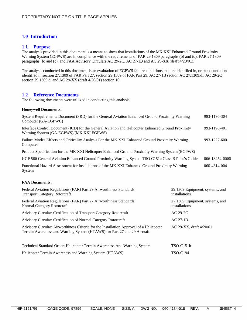
5.6 Cockpit Indication Failure The detected failure rate of the Terrain Awareness function is the sum of the detected failure rates of the LRUs that supply signals for the Terrain Awareness function.
LRUs Detected Failure Rates
GPS 81.415 x 10⁻⁶
Air Data Computer 184.50 x 10⁻⁶
EGPWC 9.363 x 10⁻⁵
Total 3.595 x 10⁻⁴
λTA = 3.595 x 10⁻⁴ per hour
EGPWS INOP lamp. Failure rate 4.455 x 10⁻⁶. The INOP lamp is not monitored. Applicability factor 100 %.
λINOP = 4.455 x 10⁻⁶ per hour
No Cockpit indication of detected Terrain Awareness Function Failure. The EGPWS INOP lamp failure is latent. tf = 1.0 hours, Ts = 7.0 hours
Pftainop = (1/2)λINOPλTAtf(Ts+tf)
Pftainop = (1/2) (4.455 x 10⁻⁶) (3.595 x 10⁻⁴) (1.0) (7.0+1.0) = 6.407 x 10⁻⁹ per flight
Warning lamp. Failure rate 4.455 x 10⁻⁶. The Warning lamp is not monitored. Applicability factor 100 %.
λPU = 4.455 x 10⁻⁶ per hour
Latent Warning lamp failure. There is 1 Warning lamp in the cockpit. It is assumed the cockpit lamps are tested once a day. There are 7 flights each day. tf = 1.0 hours, n = 7
Pfpu = (1/n)∑iλputf for i = 1 to n
Pfpu = (1/6)∑i(4.455 x 10-6) (1.0) = 1.782 x 10⁻⁵ per flight for i = 1 to 7
Cockpit speaker. Failure rate 2.1 x 10⁻⁶. The Cockpit speaker is not monitored. Applicability factor 100 %.
λCS = 2.1 x 10⁻⁶ per hour
Cockpit Speaker failure. This speaker is used each flight.
Pfcs = λCStf = (2.1 x 10⁻⁶) (1.0) = 2.1 x 10⁻⁶ per flight
Terrain Awareness Display / Weather Radar Relay. Signal undetected failure rate 2.8 x 10⁻⁶. Applicability factor 50 %.
λTWR = (2.8 x 10⁻⁶) (.50) = 1.40 x 10⁻⁶ per hour
Terrain Awareness Display Relay Failure.

PROPRIETARY NOTICE ON TITLE PAGE APPLIES
HIF-2121/R6 CAGE CODE: 97896 SCALE: NONE SIZE: A DWG NO. 060-4134-018 REV: A SHEET 22
Pftwr = λTWRtf = (1.40 x 10⁻⁶) (1.0) = 1.40 x 10⁻⁶
Terrain Awareness Display can be a Weather Radar indicator or a designated display. Signal undetected failure rate 11.355 x 10⁻⁶. Applicability factor 30 %.
λTAD = (11.355 x 10⁻⁶) (.30) = 3.407 x 10⁻⁶
Terrain Awareness Display Failure.
Pftad = λTADtf = (3.407 x 10⁻⁶) (1.0) = 3.407 x 10⁻⁶
No Terrain Awareness Warning indicated on the Cockpit Display.
Pftadw = Pftad + Pftwr = 3.407 x 10⁻⁶ + 1.40 x 10-6 = 4.807 x 10⁻⁶ per flight
No Cockpit indication of Terrain Awareness Pull Up Warning.
Pftaw = (Pfpu) (Pfcs ) (Pftadw)
Pftaw = (1.782 x 10⁻⁵) (2.1 x 10⁻⁶) (4.807 x 10⁻⁶) = 1.799 x 10⁻¹⁶ per flight
Cockpit Indication Failure.
Pfcockpit ind. = (Pftaw) + (Pftainop) = 1.799 x 10⁻¹⁶ + 6.407 x 10-9 = 6.407 x 10⁻⁹ per flight
5.7 EGPWC Fault Probability of Failure per flight for an undetected or latent failure of the EGPWC.
Pfeg = 2.083x 10⁻⁶ per flight
5.8 Probability of the Unannunciated Loss of a Terrain Awareness Pull Up Caution/Warning The probability per flight for an Unannunciated Loss of a Terrain Awareness Pull Up Caution/Warning due to undetected or latent failures. Using an EGPWC with an external GPS source, this is the worst-case scenario.
Pf = Pfpos + Pftrk + Pfgalt + Pfar + Pfeg + Pfgs + Pfcockpit ind.
Pf = 1.071 x 10⁻⁷ + 7.142 x 10⁻⁸ + 8.927 x 10⁻⁹ + 3.075 x 10⁻⁶ + 2.083 x 10⁻⁶ + 3.571 x 10⁻⁸ + 6.407 x 10-9 = 5.387 x 10⁻⁶ per flight
The probability per flight hour:
Pfhr = Pf / tf = 5.387 x 10⁻⁶ / 1.0 = 5.387 x 10⁻⁶ per flight hour

PROPRIETARY NOTICE ON TITLE PAGE APPLIES
HIF-2121/R6 CAGE CODE: 97896 SCALE: NONE SIZE: A DWG NO. 060-4134-018 REV: A SHEET 23
Figure 5-1: Fault Tree, Unannunciated Loss of the Terrain Awareness Pull Up Caution/Warning, 1 of 2.
(Page 1 of 2)
Unannunciated Loss ofTerrain Awareness Pull Up
Warning
Pf : Probability (per flight)λ: Undetected Failure Rate (per hour)tf : Average flight (hours)
Cockpit indicationfailure
Pf : 6.407 x 10⁻⁹
Pf : 5.387 x 10⁻⁶
Pf : 2.083 x 10⁻⁶
Pf : 3.075 x 10⁻⁶
λ: 3.075 x 10⁻⁶ /Htf : 1.0 H
1 Page 2
True Track error
TA corrected altitude isgreater than the actual
aircraft altitude
Position error
Pf : 8.927 x 10⁻⁹
EGPWC Fault
Pf : 1.071 X 10⁻⁷
Longitude errorLatitude error
Pf : 5.356 x 10⁻⁸
λ: 5.356 x 10⁻⁸ /Htf : 1.0 H
Pf : 5.356 x 10⁻⁸
λ: 5.356 x 10⁻⁸ /Htf : 1.0 H
The Pf for this event wasfound to be much less thanthe other branch of this treeand is consideredinsignificant to this analysis.
Pf : 8.927 x 10⁻⁹
λ: 8.927 x 10⁻⁹ /Htf : 1.0 H
Groundspeedindicates a speed
of 60 knots orless
Geometric Altitude isgreater than actual
GPS Altitude is muchgreater than other altitude
inputs
Pf : 7.142 X 10⁻⁸
Pf : 3.571 x 10⁻⁸
λ: 3.571 x 10⁻⁸ /Htf : 1.0 H
Pf : 3.571 x 10⁻⁸
λ: 3.571 x 10⁻⁸ /Htf : 1.0 H
N/S Velocity error E/W Velocityerror
Pf : 3.571 x 10⁻⁸
λ: 3.571 x 10⁻⁸ /Htf : 1.0 H
Altitude Rateindicates anascent rate
PROPRIETARY NOTICE ON TITLE PAGE APPLIES
HIF-2121/R6 CAGE CODE: 97896 SCALE: NONE SIZE: A DWG NO. 060-4134-018 REV: A SHEET 24
Figure 5-2: Fault Tree, Unannunciated Loss of the Terrain Awareness Pull Up Caution/Warning, 2 of 2.
(Page 2 of 2)
Cockpit indication failure
No Cockpit indication ofTerrain Awareness Pull Up
Warning
No Cockpit indication ofdetected Terrain
Awareness Function Failure
Pf : 1.799 x 10⁻¹⁶
λ: 4.455 x 10⁻⁶ /HTs : 7.0 H
λ: 3.595 x 10⁻⁴ /Htf : 1.0 H
No Terrain AwarenessWarning indicated on
Cockpit Display
Pf : 6.407 x 10⁻⁹
Pf : 3.407 x 10⁻⁶
λ: 3.407 x 10⁻⁶ /Htf : 1.0 H
Pf : 6.407 x 10⁻⁹
Pf : 4.807 x 10⁻⁶
Pf : 1.40 x 10⁻⁶
λ: 1.40 x 10⁻⁶ /Htf : 1.0 H
Pf : 2.1 x 10⁻⁶
λ: 2.1 x 10⁻⁶ /Htf : 1.0 H
Pf : 1.782 x 10⁻⁵
λ: 4.455 x 10⁻⁶ /Htf : 1.0 Hn : 7.0 flights
Pf : Probability (per flight)λ: Undetected Failure Rate (per hour)tf : Average flight (hours)Ts: Flight hours between self testsn: number of flights
1Page 1
Terrain AwarenessDisplay Failure
TAD Relay Failure
Latent EGPWS INOPLamp Failure
Cockpit SpeakerFailure
Latent Warning LampFailure
BIT detected failure of TerrainAwareness Function

PROPRIETARY NOTICE ON TITLE PAGE APPLIES
HIF-2121/R6 CAGE CODE: 97896 SCALE: NONE SIZE: A DWG NO. 060-4134-018 REV: A SHEET 25
6.0 Hazardously Misleading Information on the Terrain Awareness Display The Fault Tree Analysis for this event is presented in Figure 6-1. The cockpit indicators are 1 Warning lamp (visual), the cockpit speaker (aural), and the Terrain Awareness Display (visual). The Applicability Factors used in the analysis of this failure condition are identified in Table 6-1: Signals, sources, and Applicability Factors..
Table 6-1: Signals, sources, and Applicability Factors.
Signals input/output Applicability factors Possible sources (LRU)
Latitude 15 % GPS
Longitude 15 % GPS
N/S Velocity 10 % GPS
E/W Velocity 10 % GPS
Groundspeed 10 % GPS
TA altitude 2.5 % GPS - Geometric Altitude
Altitude Rate 30 % ADC - derived from Uncorrected Barometric Altitude
TA Display Range 10 % Terrain Awareness and or Wx Radar Indicator
EGPWC with Internal GPS Pfeg = 2.082 x 10⁻⁶
6.1 Position Fault Latitude from the GPS. Signal undetected failure rate 0.357 x 10⁻⁶. Applicability factor 15 %.
λLAT = (0.357 x 10⁻⁶) (.15) = 5.356 x 10⁻⁸ per hour
Latitude error.
Pflat = λLATtf = (5.356 x 10⁻⁸) (1.0) = 5.356 x 10⁻⁸ per flight
Longitude from the GPS. Signal undetected failure rate 0.357 x 10⁻⁶. Applicability factor 15 %.
λLNG = (0.357 x 10⁻⁶) (.15) = 5.356 x 10⁻⁸ per hour
Longitude error.
Pfng = λLNGtf = (5.356 x 10⁻⁸) (1.0) = 5.356 x 10⁻⁸ per flight
Position error.
Pfpos = Pflat + Pfng = 5.356 x 10⁻⁸ + 5.356 x 10-8 = 1.071 x 10⁻⁷ per flight

PROPRIETARY NOTICE ON TITLE PAGE APPLIES
HIF-2121/R6 CAGE CODE: 97896 SCALE: NONE SIZE: A DWG NO. 060-4134-018 REV: A SHEET 26
6.2 Track Fault N/S Velocity from the GPS. Signal undetected failure rate 0.357 x 10⁻⁶. Applicability factor 10 %.
λNS = (0.357 x 10⁻⁶) (.10) = 3.571 x 10⁻⁸ per hour
N/S Velocity error.
Pfns = λNStf = (3.571x 10⁻⁸) (1.0) = 3.571 x 10⁻⁸ per flight
E/W Velocity from the GPS. Signal undetected failure rate 0.357 x 10⁻⁶. Applicability factor 10 %.
λEW = (0.357 x 10⁻⁶) (.10) = 3.571 x 10⁻⁸ per hour
E/W Velocity error.
Pfew = λEWtf = (3.571x 10⁻⁸) (1.0) = 3.571 x 10⁻⁸ per flight
Track error.
Pftrk = Pfns + Pfew = 3.571 x 10⁻⁸ + 3.571 x 10-8 = 7.142 x 10⁻⁸ per flight
6.3 Groundspeed Fault Groundspeed from the GPS. Signal undetected failure rate 0.357 x 10⁻⁶. Applicability factor 10 %.
λGS = (0.357 x 10⁻⁶) (.10) = 3.571 x 10⁻⁸ per hour
Groundspeed indicates a speed greater than the actual.
Pfgs = λGStf = (3.571 x 10⁻⁸) (1.0) = 3.571 x 10⁻⁸ per flight
6.4 GPS Altitude Error GPS Altitude from the GPS. Signal undetected failure rate 0.357 x 10⁻⁶. Applicability factor 2.5 %.
λGPS = (0.357 x 10⁻⁶) (.025) = 8.927 x 10⁻⁹ per hour
GPS Altitude is much greater than all the other altitude inputs.
Pfgps = λGPStf = (8.927 x 10⁻⁹) (1.0) = 8.927 x 10⁻⁹ per flight
6.5 Altitude Rate Fault Altitude Rate derived from Uncorrected Barometric Altitude from the ADC. Signal undetected failure rate 10.25 x 10⁻⁶. Applicability factor 30 %.
λAR = (10.25 x 10⁻⁶) (.30) = 3.075 x 10⁻⁶ per hour
Altitude Rate indicates an ascent rate.
Pfar = λARtf = (3.075 x 10⁻⁶) (1.0) = 3.075 x 10⁻⁶ per flight

PROPRIETARY NOTICE ON TITLE PAGE APPLIES
HIF-2121/R6 CAGE CODE: 97896 SCALE: NONE SIZE: A DWG NO. 060-4134-018 REV: A SHEET 27
6.6 Display Range Fault The Display Range is from the Terrain Awareness Display. This can be a Weather Radar indicator or a designated display. Signal undetected failure rate 11.355 x 10⁻⁶. Applicability factor 10 %.
λTAD = (11.355 x 10⁻⁶) (.10) = 1.136 x 10⁻⁶
Terrain Awareness Display Range error.
Pftad = λTADtf = (1.136 x 10⁻⁶) (1.0) = 1.136 x 10⁻⁶
6.7 EGPWC Fault Probability of Failure per flight for an undetected or latent failure of the EGPWC.
Pfeg = 2.082x 10⁻⁶ per flight
6.8 Probability of Hazardously Misleading Information on the Terrain Awareness Display The probability per flight of Hazardously Misleading Information on the Terrain Awareness Display due to undetected and/or latent failures. Using an EGPWC with an external GPS source, this is the worst-case scenario.
Pf = Pfpos + Pftrk + Pfgs + Pfgalt + Pfar + Pftad + Pfeg
Pf = 1.071 x 10⁻⁷ + 7.142 x 10⁻⁸ + 3.571 x 10⁻⁸ + 8.927 x 10⁻⁹ + 3.075 x 10⁻⁶ + 1.136 x 10⁻⁶ + 2.082 x 10-6 = 6.516 x 10⁻⁶ per flight
The probability per flight hour:
Pfhr = Pf / tf = 6.516 x 10⁻⁶ / 1.0 = 6.516 x 10⁻⁶ per flight hour

PROPRIETARY NOTICE ON TITLE PAGE APPLIES
HIF-2121/R6 CAGE CODE: 97896 SCALE: NONE SIZE: A DWG NO. 060-4134-018 REV: A SHEET 28
Figure 6-1: Fault Tree, Hazardously Misleading Information on the Terrain Awareness Display.
(Page 1 of 1)
Hazardously MisleadingInformation on the Terrain
Awareness Display
Pf : Probability (per flight)λ: Undetected Failure Rate (per hour)tf : Average flight (hours)
Pf : 6.516 x 10⁻⁶
Pf : 2.082 x 10⁻⁶
Pf : 3.075 x 10⁻⁶
λ: 3.075 x 10⁻⁶ /Htf : 1.0 H
True Track error
TA corrected altitude isgreater than the actual
aircraft altitude
Position error EGPWC Fault
Pf : 1.136 x 10⁻⁶
λ: 1.136 x 10⁻⁶ /Htf : 1.0 H
Pf : 1.071 X 10⁻⁷
Longitude errorLatitude error
Pf : 5.356 x 10⁻⁸
λ: 5.356 x 10⁻⁸ /Htf : 1.0 H
Pf : 5.356 x 10⁻⁸
λ: 5.356 x 10⁻⁸ /Htf : 1.0 H
Pf : 7.142 X 10⁻⁸
Pf : 3.571 x 10⁻⁸
λ: 3.571 x 10⁻⁸ /Htf : 1.0 H
Pf : 3.571 x 10⁻⁸
λ: 3.571 x 10⁻⁸ /Htf : 1.0 H Pf : 8.927 x 10⁻⁹
The Pf for this event wasfound to be much less thanthe other branch of this treeand is consideredinsignificant to this analysis.
Pf : 8.927 x 10⁻⁹
λ: 8.927 x 10⁻⁹ /Htf : 1.0 H
Weather RadarDisplay Range
error
Geometric Altitude isgreater than actual
GPS Altitude is muchgreater than other altitude
inputs
N/S Velocity error E/W Velocityerror
Groundspeedindicates a speedgreater than the
actual
Pf : 3.571 x 10⁻⁸
λ: 3.571 x 10⁻⁸ /Htf : 1.0 H
Altitude Rateindicates anascent rate

PROPRIETARY NOTICE ON TITLE PAGE APPLIES
HIF-2121/R6 CAGE CODE: 97896 SCALE: NONE SIZE: A DWG NO. 060-4134-018 REV: A SHEET 29
7.0 Impact of HTAWS Failures on External Devices and Impact on HTAWS due to External Device Failures
FHA 060-4314-004 identifies two major failure conditions that require mitigation (1) EGPWC failures that could cause failures in external devices and (2) external device failures that could cause failures in the EGPWC. The EGPWC design ensures that the probability of these types of major failures will not exceed 1 x 10⁻⁵ per flight hour by properly isolating the EGPWC interfaces to external devices (e.g. ARINC 429 buses). These interface techniques (e.g. providing high input and output series resistors on input and output ports) ensure that shorts at the inputs of receivers or outputs of drivers in the EGPWC are isolated from the external bus. The probability of the resistor and driver (or receiver) both failing in a manner resulting in corruption of the bus is on the order of 10-17 per flight hour (e.g. the resistor fails short (10-9) AND the driver (or receiver) shorts to ground or the power rail (10-8)). A more probable failure mode would be a manufacturing error (e.g. involving the connector or the circuit board fabrication on the side of the resistor where the PCB trace routes to the connector) that shorts the bus to ground or power (10-9) after final manufacturing vibration testing. This value (10-9) is supported by over 1 billion flight hours accumulated by all EGPWS units with no reported failures of this type. Other scenarios, including the case where only the resistor opens up, result in a loss of the serial channel’s function, but has no effect on an external devices’ ability to continue operating.
In addition to using high impedance interfaces, EGPWC incorporates the following design methods:
• Hardware enforced software partitioning is used within the EGPWC to ensure independence between basic GPW functions and Terrain/Obstacle Awareness (TA) functions.
• The EGPWC interfaces to aircraft sensors and systems that operate independently of the EGPWC and do not require input from the EGPWC to function properly.
• The EGPWC interfaces with only one of the available channels from an aircraft sensor or system.
• The EGPWC maintains the isolation and independence of aircraft sensors and systems with which it interfaces.

PROPRIETARY NOTICE ON TITLE PAGE APPLIES
HIF-2121/R6 CAGE CODE: 97896 SCALE: NONE SIZE: A DWG NO. 060-4134-018 REV: A SHEET 30
8.0 Conclusion The analysis provided in this document shows that installations of the Honeywell International MK XXI EGPWS meet or exceed the requirements of FAR Part 25, section 25.1309, AC25.1309-1A, TSO-C194, RTCA/DO-309 and Functional Hazard Assessment (FHA) 060-4314-004. Table 8-1 provides the results of the calculated probability of occurrence per flight hour for each of the failure conditions evaluated in this document. Refer to FHA 060-4314-004 for a list of all failure conditions and failure condition classifications, including those classified as minor.
Some analyses combine similar failure conditions
• Unannunciated Loss of Caution/Warning analysis includes both (1) loss of warning function and (2) loss of caution function
• False Annunciation analysis includes both TA Warning and TA cautions
• Hazardously Misleading Data on the Terrain Display combines corrupted display/valid position display and display of terrain not in the current position. The analysis is valid for both standard terrain displays and peaks terrain displays.
• The analysis related to HTAWS failures corrupting external devices or external device failures corrupting HTAWS combines 2 failure conditions from the FHA (e.g. (1) HTAWS failure affects the integrity of the interface to an external device (2) Failure of a device interfaced to HTAWS affects the integrity of HTAWS functions (other than those using data from the device)).
Table 8-1: Summary Table, Probability of Failure per Flight Hour.
Failure Condition Applicable Regulations Probability of Failure per Flight Hour (Pfhr)
Section number
Loss of all EGPWS Functions FAR Part 27, 27.1309 (b) (c) AC 27-1B, AC 27.1309. d. AC 25-23, 9. b. (1)
1.970 x 10⁻⁴ 3.3
False Annunciation of Terrain Awareness “Pull Up” Caution/Warning
FAR Part 29, 29.1309 (b) AC 29-2C, AC 29.1309. d. AC 29-XX, draft 4/20/01, 10. c. (1) AC 25-23 9. b. (2)
2.583 x 10⁻⁶ 4.6
Unannunciated loss of the Terrain Awareness “Pull Up” Caution/Warning
FAR Part 29, 29.1309 (b) AC 29-2C, AC 29.1309. d. AC 29-XX, draft 4/20/01, 10. c. (2) AC 25-23 9. b. (3)
5.387 x 10⁻⁶ 5.8
Hazardously Misleading Information on the Terrain Awareness Display
FAR Part 29, 29.1309 (b) AC 29-2C, AC 29.1309. d. AC 29-XX, draft 4/20/01, 10. c. (3) AC 25-23 9. b. (4)
6.516 x 10⁻⁶ 6.8
HTAWS failure corrupts external device or failure of an external device corrupts HTAWS
AC 29-XX, draft 4/20/01, 10.c.(4) AC 25-23 9.b.(5) 1 x 10⁻⁹ 7.0

![SotC SRD - Fate · SotC SRD SotC SRD Spirit of the Century (OGL SRD) ... °On Top Of It ... °Heart’s Secret [Empathy]](https://img.dokumen.tips/doc/110x75/5b367e717f8b9aec518e8e59/sotc-srd-sotc-srd-sotc-srd-spirit-of-the-century-ogl-srd-on-top-of.jpg)