Embed Size (px)
Citation preview

Title: Parasitic Error-free Symmetric Diaphragm Flexure, and a set of precision compliant mechanisms based it: Three and Five DOF flexible torque couplings, Five DOF motion stage, single DOF linear/axial bearing.
Inventors: Shorya Awtar, Alexander H. Slocum Three Degrees of Freedom (DOF) Diaphragm Flexures Diaphragm flexures are commonly used for providing motion in the direction normal to the flexure plane. Many versions of the design shown in Fig.1 have been frequently encountered in the literature and in numerous devices/applications [1-3]. Because of its geometry, apart from a Z translation, this flexure is also compliant in roll and pitch motions (i.e. rotations about the X and Y axes). Any diaphragm flexure made from thin sheetmetal will typically have these three degrees of freedom, and will be very stiff in the two planer directions, X and Y, and in yaw (i.e. rotation about the Z axis). An evident drawback of this design is that it suffers from a parasitic Z-twist associated with Z translation. The reason is for this twist becomes obvious when one recognizes that each of the peripheral arms (or blades) in this design behaves like a fixed-free cantilever, as shown in Fig.2. For a fixed-free cantilever, any motion δ in the desired direction is associated with a transverse motion e, also referred to as parasitic error motion, so as to maintain a constant arc length of the cantilever. Theory of linear elasticity provides us with the following results
23
and 3FL eEI L L
δδ ⎛ ⎞= ≈ ⎜ ⎟⎝ ⎠
Fig.1
Fig. 2 Parasitic Motion
Desired Motion
X
YZ
Parasitic Motion
Desired Motion
F
δ
e

Shorya Awtar MIT Confidential 2
Applying this fact to each arm (also referred to as blade or beam in this document) of the flexure mechanism in Fig.1, it is easily seen that any Z direction translation of the diaphragm causes the tip of each blade to move slightly towards its respective fixed support, hence producing an overall CCW motion. The planer geometry of the diaphragm flexure inherently precludes parasitic errors in X and Y directions. We present an alternative diaphragm flexure design in which the above-mentioned parasitic error motion is eliminated by exploiting symmetry, as shown in Fig.3. In this case though, a build-up of axial stresses in each blade can significantly increase the stiffness of the flexure mechanism. To make the mechanism more compliant, the effective length of each flexure arm is doubled by folding it back once, as shown in Fig.4. Folding back the flexure arms not only increases the effective length but also eliminates axial stresses in the arms. Thus, with this arrangement of symmetrically folded back flexure arms, we are able to obtain a larger range of motion, higher compliance in the desired direction of motion, lower buildup of stresses in the flexure blades, and at the same we have been successful in minimizing the parasitic Z twist.
Fig.3
Fig.4
Shorya Awtar MIT Confidential 3
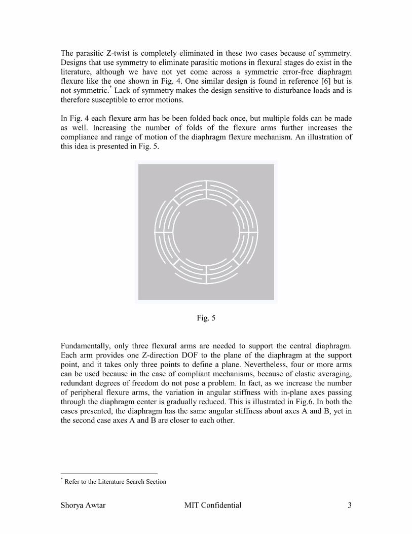
The parasitic Z-twist is completely eliminated in these two cases because of symmetry. Designs that use symmetry to eliminate parasitic motions in flexural stages do exist in the literature, although we have not yet come across a symmetric error-free diaphragm flexure like the one shown in Fig. 4. One similar design is found in reference [6] but is not symmetric.* Lack of symmetry makes the design sensitive to disturbance loads and is therefore susceptible to error motions. In Fig. 4 each flexure arm has be been folded back once, but multiple folds can be made as well. Increasing the number of folds of the flexure arms further increases the compliance and range of motion of the diaphragm flexure mechanism. An illustration of this idea is presented in Fig. 5.
Fig. 5 Fundamentally, only three flexural arms are needed to support the central diaphragm. Each arm provides one Z-direction DOF to the plane of the diaphragm at the support point, and it takes only three points to define a plane. Nevertheless, four or more arms can be used because in the case of compliant mechanisms, because of elastic averaging, redundant degrees of freedom do not pose a problem. In fact, as we increase the number of peripheral flexure arms, the variation in angular stiffness with in-plane axes passing through the diaphragm center is gradually reduced. This is illustrated in Fig.6. In both the cases presented, the diaphragm has the same angular stiffness about axes A and B, yet in the second case axes A and B are closer to each other.
* Refer to the Literature Search Section

Shorya Awtar MIT Confidential 4
Fig. 6 Because of symmetry, the center of stiffness for this diaphragm flexure mechanism, with respect to normal (i.e., out of plane) loads, lies at the center of the diaphragm. But if necessary (for example, some applications may require the diaphragm center to be hollow), the center of stiffness of the diaphragm flexure mechanism can be shifted to any arbitrary point in the plane of the flexure, by varying the blade width and/or thickness from one folded-back arm unit to another. As an example, the center of the stiffness of the diaphragm flexure in Fig.7, with respect to normal loads, has been shifted to the right by making the left folded-back arm unit more compliant in comparison to the right folded-back arm unit. The approximate location of the center of stiffness in this case is marked by the crosshair. Nevertheless, symmetry of each folded-back arm unit is preserved about its respective midpoint, and hence parasitic Z-twist is still avoided.
Fig 7
Axis A Axis A
Axis B
Axis B

Shorya Awtar MIT Confidential 5
All these diaphragm flexures provide three constraints and three DOF. Therefore, this flexure mechanism can be used as a torque coupling; it is simply a monolithic version of the universal joint with an additional DOF in the Z-direction.

Shorya Awtar MIT Confidential 6
Five DOF Motion Stage An interesting flexural stage is obtained by connecting two diaphragm flexures placed apart in the Z-direction. A schematic and prototype are shown in Fig.6. The outer periphery of one diaphragm flexure mechanism is connected to a base frame, while the inner diaphragm is rigidly connected to the inner diaphragm of a second diaphragm flexure by means of an intermediate frame. The outer periphery of the second diaphragm flexure mechanism is connected to the moving frame.
BaseFrame
Z
Y
MovingFrame
DiaphragmFlexure 1
DiaphragmFlexure 2
IntermediateFrame
Fig. 6
X
Z
Y

Shorya Awtar MIT Confidential 7
In this arrangement, the moving frame has five degrees of freedom with respect to the base frame: three translations in X, Y and Z; and two rotations about X and Y. Each diaphragm flexure contributes three DOF, but since the Z-translation DOF of the two diaphragms are coincident, one of them is redundant. Thus, overall the stage has five DOF. Furthermore, the Z-translation is free of any parasitic twists. The fact that this flexural system provides a pure rotational constraint makes it suitable for use as a five DOF torque coupling. One possible design embodiment of this idea is shown in Fig. 7. Two shafts can be attached to either end of this tuna-can shaped coupling. A second design embodiment based on the same idea, applied in a slightly different geometry, is presented in Fig.8. Basic prototypes of these designs have been made by means of Fused Deposition Modeling as an initial proof-of-concept. The latter design looks similar the standard helical coupling, but it does not suffer from wind-up errors that are typical in helical couplings. A similar (but NOT the same) design concept is found in reference [4] but has limited compliance and range of motion when compared to the proposed embodiment. Furthermore, the design found in reference [4] suffers from axial stresses in the arms/blades.* Bellows coupling and helical coupling are some of the typical 5 DOF torque couplings found in the existing literature [4-5]. Fig.7
Fig.8 * Refer to the Literature Search Section

Shorya Awtar MIT Confidential 8
Precision Linear Bearing Based on the Symmetric Diaphragm Flexure described above, a possibly new kind of linear (or axial) bearing system is proposed that has high accuracy and repeatability, thus making it ideal for precision systems in metrology, motion control, optical instrumentation, etc. The invention comprises of two symmetric diaphragm flexures assembled parallel to each other as shown in Figure 9. There are three basic elements in the bearing system: a housing, which is rigidly attached to the outer periphery of both the diaphragm flexures; a reciprocator, which is attached to the inner diaphragms of both the diaphragm flexures; the two diaphragm flexures that allow for a guided motion between the housing and the reciprocator. This arrangement of by itself is an old concept [7], but the use of symmetric diaphragm flexures makes it ‘possibly’ novel.
Fig. 9
This bearing arrangement provides a highly precise motion in the axial direction with low compliance, zero friction and a relatively large stroke as compared to many other designs [3]. Furthermore, the bearing system is very stiff in all the other five motions: X and Y translations, and three rotations. All the previously mentioned advantages of the symmetric diaphragm flexure are present here as well.
Reciprocator
Housing
Diaphragm Flexures

Shorya Awtar MIT Confidential 9
Claims
• A planer diaphragm flexure mechanism with multiple symmetrically folded back flexural arms or U-shaped beams connecting a central structure to an outer structure, thus providing one linear and two rotary degrees of freedom, and high stiffness in torsion and the other two linear directions.
• Parasitic Z-twist is completely eliminated in the proposed design due to the symmetric back-folded flexural beam units.
• Folding back of the beams also eliminates axial stresses, which in turn reduces stiffness in the desired motion, and also avoids non-linear stiffening of the structure
• A family of multiple degrees of freedom flexural mechanism based on the above-mentioned basic diaphragm flexure design is proposed. These flexural mechanisms provide multiple degrees of freedom by employing parallel kinematics rather than serial kinematics, and hence have compact embodiments.
- A three DOF flexural universal joint - A five DOF motion stage - Two flexible couplings, which provide a pure rotational constraint (i.e.
high torsional stiffness) and allow for lateral and axial shaft offsets as well as angular misalignments, are proposed.
- A single DOF linear/axial flexural bearing (described in the addendum section that follows)
• Parasitic errors that typically plague parallel kinematics based designs, are eliminated or minimized in the above embodiments by means of symmetry. Some other designs like the helical coupling, for example, have windup errors in the presence of torsion, thus making them unusable for precision applications.
• All the flexure designs presented in this document, allow for a frictionless, wear-free and highly repeatable motion.
• Inexpensive mass production: Standard manufacturing processes of sheet-metal stamping, deep drawing, hydro forming, laser cutting and water-jet cutting can be used to manufacture these machine elements. The diaphragm flexure can be inexpensively mass-manufactured by the process of sheetmetal stamping. Mass production of the proposed couplings is possible because of their simple monolithic designs that require no assembly.
• As shown in Fig. 7, the folded back beams that constitute the diaphragm flexure need not all be identical. The geometric parameters (length, width and thickness) of each individual folded back beam may be chosen independently to tailor the force-displacement characteristic of the resulting diaphragm flexure and any other embodiment that makes use of the diaphragm flexure. For example, in Fig. 7 one set of folded-back beams is thinner than all the others, thus shifting the center of stiffness of the mechanism slight to the right. Variation in the characteristics of individual folded-back beams that constitute the diaphragm flexure provides a very powerful design tool.

Shorya Awtar MIT Confidential 10
Potential Applications We foresee these above designs as fundamental building blocks in precision mechanisms and machines. The applications for such devices can be numerous only some of which are being listed here. 1) Diaphragm valves can be used for pressure sensing and flow control equipment.
Reference [8] presents one such application and also quotes the prior art on Metal Diaphragm that have been used in differential pressure units (DPU).
2) Linear drive / reciprocating compressors: This is a very common application for the linear bearing system presented in this document. References [1-3] provide details of application of such a linear bearing systems in cyrogenic refrigerators and cryo-coolers. Reference [2] mentions many other applications of the diaphragm flexure other than cryo-coolers, for example, artificial heart valves, an ultraviolet sensor shutter system, etc.
3) The linear bearing design can be used in voice coil actuator assemblies to provide perfect linear motion [7]. This idea could also be possibly be used for making high-performance speakers. (Meeting with Rakesh Pandey, Bose Corporation)
4) The flexible couplings present inexpensive, mass-manufacturable and error-free substitutes to existing torque couplings in the automotive industry.
5) These couplings are also valuable for precision machines that cannot tolerate any error motions (e.g. a common helical coupling has wind-up errors and is unfit for use in precision machines)
6) The linear bearing can be used for motion guidance in high precision metrology systems and servo-systems that perform meso or micro scale machining.
7) Many optical instruments require accurate and precise adjustments of units like mirrors, lenses, gratings etc. in the form of repeatable translations and rotations in certain specific directions. The above-described compliant mechanisms can be of immense value for such optical instruments.
8) These designs are very well suited for MEMS applications. The diaphragm flexure can be used in the design of various micro and nano valves. The multiple degree of freedom stages can provide exactly constrained motion in micro actuators and bearing/suspension systems.

Shorya Awtar MIT Confidential 11
References and Background Search
1. US Patent No. 6,050,556, “Flexure Bearing”, 2000 This application presents a version of the concept illustrated in Figure 1. It claims to be an improvement of over the prior art in terms of reduced stress concentration. The prior art mentioned in this patent application also belongs to same category as the Figure 1 design. The flexure bearing is presented in the context of a linear drive compressor.
2. US Patent No. 5,492,313, “ Tangential Linear Flexure Bearing”, 1996 This is another version of the concept shown in Figure 1. The inventors claim, “the improvements being within the flexure blades having symmetrical opposing end angles and ends equally displaced from radial lines extending from the center of the diaphragm, and having grain orientation extending along the length of the flexure blades, both features providing improved radial stiffness, low axial stiffness, reduced flexure stresses and increased fatigue strength for improved reliability.” A detailed description of applications of such flexures in reciprocating cryo-coolers is provided in the ‘Background of the Invention’ section. The use of these diaphragm flexure bearings in an artificial art application and an ultraviolet shutter system is also mentioned. This patent presents some prior art designs, which once again fall into the category of Figure 1 design.
3. US Patent No. 6,129,527, “Electrically Operated Linear Motor with Integrated Flexure Spring and Circuit for use in Reciprocating Compressor”, 1999 Once again, this presents another version of the figure 1 design, primarily for use in reciprocating compressors. Also mentions prior art, which offers nothing new. Mentions applications in cryogenic refrigerators and cryo-coolers.
4. Larry L. Howell, “ Compliant Mechanisms”, John-Wiley and Sons, Inc. Presents a compliant Orthoplaner Spring: An idea that is close to ours, in the sense that it makes use of folded back beams for out of plane diaphragm motion, but the design is not symmetric. Folding back of the arms does produce the advantages of increased compliance and reduced axial stresses in the beam. But lack of symmetry increase sensitivity to disturbance loads since symmetry provides further constraints that get rid of possible parasitic errors. Furthermore, the design presented in this book is not equally stiff in torsion in both directions.
5. Flexure Springs from the FotoFab Catalog Make use of folded back beams, an idea very similar to what we propose. Uses only two beams, whereas we think that at least three must be used.
6. Folded-back beam design from the Sensors and Actuators Paper: An idea very similar to what we are proposing.
7. Stephen D. Senturia, “Microsystem Design”, Kluwer Academic Publishers, 2001 A case-study in this book provides a design layout of the MEMS accelerometer
manufactured by Analog Devices, Inc. This design makes use of a symmetric folded-back beam mechanism for in plane motion, as opposed to our design which allows for out of plane motion.
8. Smith, S. T, “ Flexures: Elements of Elastic Mechanisms”, 2000 A chapter in this book illustrates a compliant coupling design that in some ways is similar to the coupling design presented in Figure 8. But this design doesn’t make
Shorya Awtar MIT Confidential 12
use of the folded back arms, and hence has higher axial stressed in the flexure beams, reducing the range of motion and increasing the stiffness.
9. The same kind of coupling as mentioned above is also manufactured by Renbrandt. We have been doing an FEM analysis to compare the existing design without folded back beams, and the design with folded back beams that we have proposed. There couplings compare, and as of yet we do not see a major advantage of one over the other.
10. Douglass Blanding, “Exact Constrain: Machine Design Using Kinematic Principles”, ASME, 1999
This book presents designs for various conventional compliant couplings, for example, bellows coupling and helical coupling.
11. Voice coil Actuators, Application and Product Selection Guide, BEI Kimco Magnetics Division, Figure 12, Page 9 These application notes for a certain brand of voice coil actuators provide a linear bearing arrangement that is very similar to the one that we have depicted in Figures 9 and 10. The notes however do not specify any diaphragm flexure geometry.
The literature search that we have done till now reveals diaphragm flexure designs similar that shown in Figure 1 [1-3]. One design has been found that employs folded-back but is not symmetric [4]. The concept of folded back beams has also been used in other flexure designs [6-7]. Reference [8-9] pertain to a flexible coupling design that can be considered ‘prior art’ for the coupling design that we present in Fig. 8. Although this design is symmetric, it does not use folded-back flexure arms. The designs presented in references 5 and 6 come very close to what we propose.