Embed Size (px)
Citation preview

Fabrication, Assembly and Testing of a new X-Y Flexure Stage with substantially zero Parasitic Error Motions Shorya Awtar Precision Engineering Research Group, MIT
Fig.1 Experimental Set-up Background We have invented a new kind of planer XY flexure stage based on parallel kinematics which allows for entirely decoupled X and Y motions free of parasitic errors. Planer constraints are arranged such that two ground mounted actuators produce two motions independent of each other. Specifically,
• An X force produces an X displacement of the motion stage, and no Y displacement or rotation. Same holds true for the Y axis as well.
• The point of application of X force moves only along X direction and is not affected by a Y force. Same holds true for the Y axis as well.
Once these features are analytically and experimentally verified, they can lead to significant advantages in terms of range of motion, accuracy of motion and simplicity in motion control. Most parallel kinematics flexures have a limited range of motion since larger motions induce non-linearity and parasitic coupling, which in turn limits accuracy. Despite being parallel mechanisms, the proposed designs allow for relatively larger range of motion due to their unique arrangement of flexure building blocks. While repeatability is guaranteed by any monolithic flexure design, the proposed designs also allows for
Computer with dSpace
Cap-probe Driver
Granite Table
Flexure Plate and Metrology
Set-up

accuracy in motion due to inherent symmetry. In terms of motion control, a single control loop is required for each axis since there is a one to one correspondence between the actuator motions and the X and Y displacements of the motion stage. Hence, no additional sensors are required to directly measure the displacements of the motion stage; the optical encoders attached to the actuation motors suffice. Parallel kinematics allows for ground mounting of both actuators and hence the entire actuation mechanism for one axis doesn’t have to be dragged along the other axis, which is a typical drawback of serial mechanisms. The two most promising designs are illustrated in Figures 2 and 3.
Fig. 2
X
Y
Y Force
X Force
Base Frame
Motion Stage
Intermediate Stage
Intermediate Stage

Fig. 3 While the design of Fig.2 allows for a larger range of motion due to relatively longer blades, the design of Fig. 3 has more symmetry and also provides a larger usable area in the center. Theory has been developed to predict the exact displacements of the motion stage in the above two cases with respect to the base frame when actuation forces are applied. To be able to verify this analytically predicted performance of the flexures, we have designed and built an experimental setup. We seek to measure the following quantities or performance measures:
- Stiffness in the X and Y directions - Rotation and Y displacement of the motion stage in response to an X actuation force - Rotation and X displacement of the motion stage in response to a Y actuation force - Correspondence between the tip displacements of the actuators and the motion stage
displacements - Rotation and Y displacement of the point of X force application - Rotation and X displacement of the point of Y force application
XY
Y Force X Force
Motion Stage
Base Frame
Intermediate Stages

Design of the Experimental Set-up
Fig. 4 Exploded view of the experimental set-up
Fig 5. Assembled view of experimental set-up
Surface Plate Mounting Pad
Y Actuator
X Actuator
Flexure Plate
Reference Block
Cap Probes [1]
Top Plate
Cap Probes [2] Metrology Plate
Pins [1]
Pins [2] Pins [3]
Actuator Decoupling Flexure
The objective of this experimental set-up is to be able to assess the above-mentioned performance measures of the various XY flexure designs that we have proposed. The results of these measurements will help us verify the claims made in the previous section. The set-up is designed to be very simple as well as modular, i.e., various XY flexure stages, for example those shown in Figures 2 and 3, can be tested using the same set-up. The flexure plate is mounted on a granite surface plate by means of mounting pads that isolate the flexure plate from any ground induced vibrations. The flexure plate can remain floating and does not have to be rigidly attached to the surface plate since all force-loops are internal to the flexure plate. Various isolation schemes have been considered:
1) Use of foam pads or soft mouse pads to generate an elastically averaged support and good damping.
2) Use of three mounting legs with visco-elastic damping material (EAR) between the flexure plate and the legs. This is a more kinematic mounting.
3) Constrained layer damping of the flexure plate base frame by sandwiching a layer of viscoelastic damping material between the static portions of the flexure plate and the granite slab.
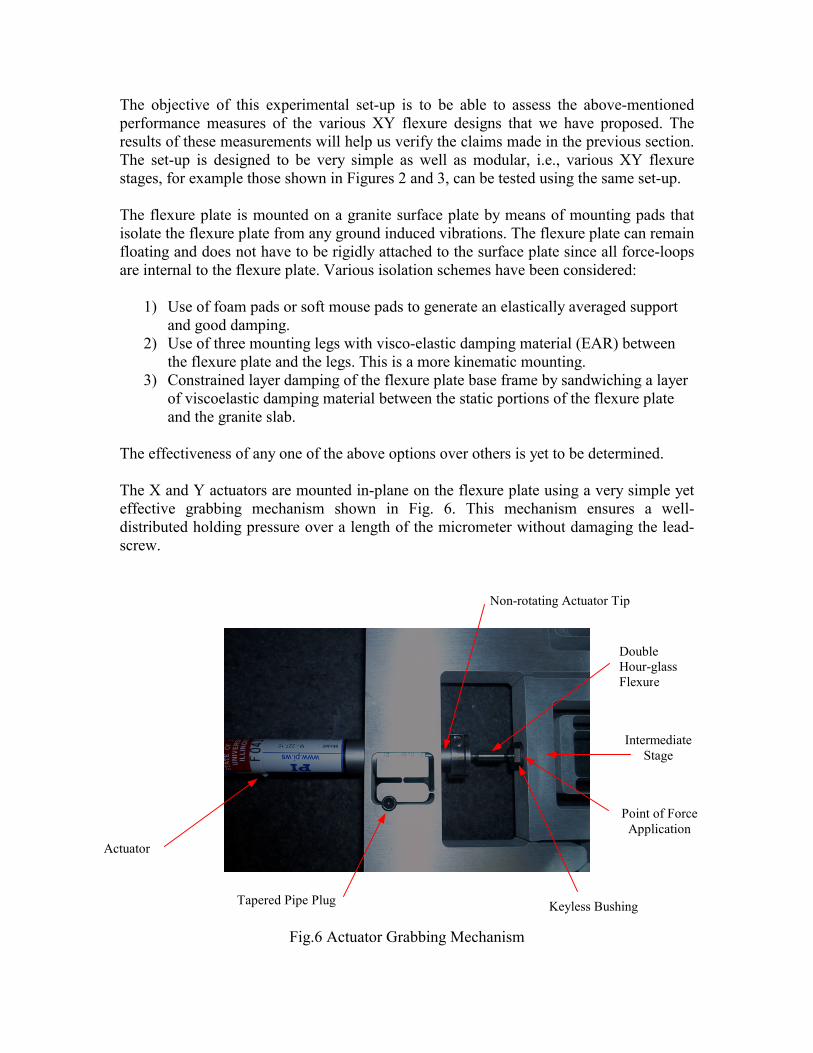
The effectiveness of any one of the above options over others is yet to be determined. The X and Y actuators are mounted in-plane on the flexure plate using a very simple yet effective grabbing mechanism shown in Fig. 6. This mechanism ensures a well-distributed holding pressure over a length of the micrometer without damaging the lead-screw.
Fig.6 Actuator Grabbing Mechanism
Actuator
Tapered Pipe Plug Keyless Bushing
Point of Force Application
Double Hour-glass Flexure
Non-rotating Actuator Tip
Intermediate Stage

Although we do not expect the point of force application on the intermediate stage of the flexure plate to have any motions other than in the direction in which actuation force is applied, nevertheless it is good design practice to introduce a flexible coupling between the actuator tip and the point of force application. This ensures that only axial force is transmitted to the intermediate stage and any other loads arising due to misalignments are absorbed by the flexible coupling. A double hour-glass flexure serves the purpose of this flexible coupling. One end of the double hourglass flexure is attached to the non-rotating cylindrical actuator tip by means of a friction clamp, while the other end is attached to the point of force application on the intermediate stage by means of a keyless bushing. Throughout the design of this experimental set-up, care has been taken so that all connections are free of backlash and are based on friction clamping. A metrology plate is mounted on the base frame of the flexure plate kinematically by three pins (Pins [2]) – for inplane location , and three shims – for normal to plane location. Springs are used for preloading the three pin - three surface inplane interface. Weight of the metrology plate preloads the three point normal-to-plane interface. The metrology plate constitutes the housing for the cap probes that are used to measure the displacement of the motion stage with respect to base frame. To meet this objective, the metrology plate is aligned and mounted on the base frame using Pins [2], and a reference block is mounted and aligned with the motion stage using Pins [3]. Since the axes of the base frame and the motion stage are aligned in the manufacturing of the flexure plate, the above arrangement ensures that the axes of the flexure plate are aligned with those of the reference block as well as those of the cap probes. This alignment is necessary to be able to obtain credible displacement measurements. Utmost care has been taken in the design and manufacturing of this experimental assembly to align the metrology plate and the reference block with the flexure axes, to be able to make good measurements. Finally on top of the metrology plate, we mount a top-plate which only needs to be parallel to the flexure plate. The top plate holds cap-probes (Cap Probes [1]) to measure the out-of-plane motions of the reference block with respect to the base frame. The top-plate doesn’t have to be precisely aligned in-plane and hence a two-hole two-pin (Pins [1]) arrangement is used. Inplane cap probes (Cap Probes [2]) are held in the metrology plates using the same grabbing mechanism that is used for the actuators. Once again, this proves to be very effective in applying a distributed pressure along the length of the cap probe without damaging the cap probe and altering its calibration. Four in-plane cap probes are required to account for a possible misalignment of the metrology frame axes with respect to the reference block axes. Three cap probes are held by the top plate by a simpler grabbing mechanism for normal-to-plane mounting. This arrangement is shown in Fig. 7.
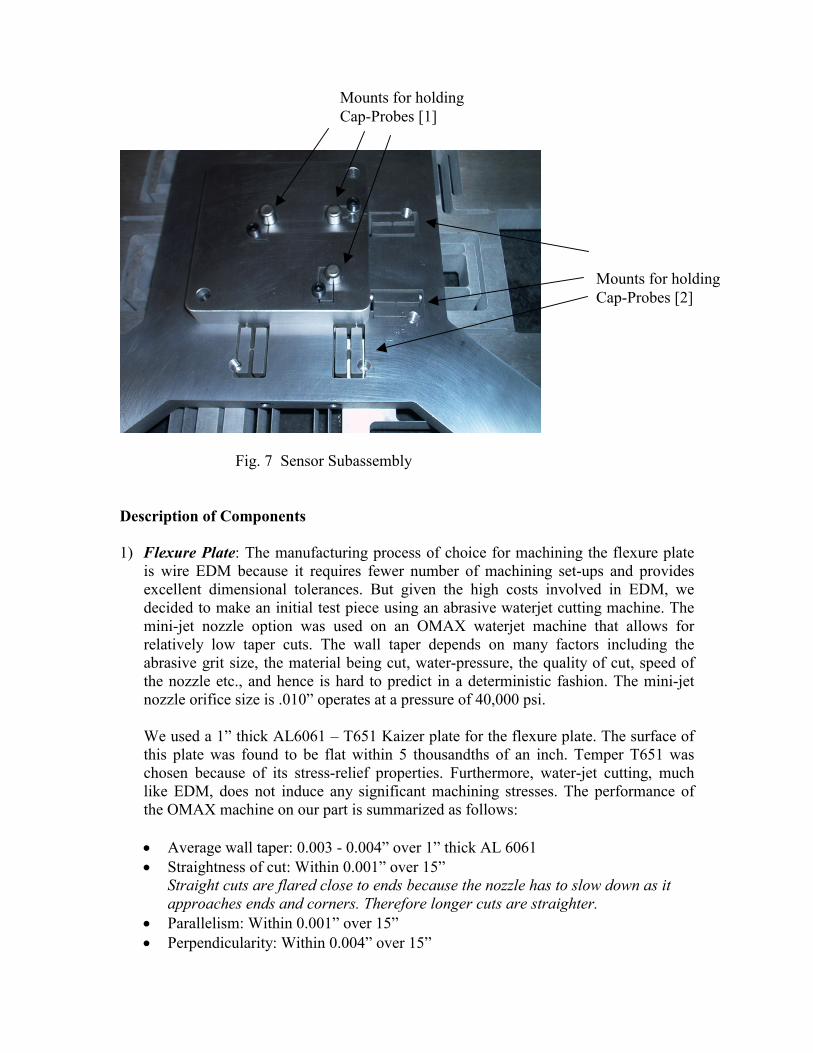
Fig. 7 Sensor Subassembly Description of Components 1) Flexure Plate: The manufacturing process of choice for machining the flexure plate
is wire EDM because it requires fewer number of machining set-ups and provides excellent dimensional tolerances. But given the high costs involved in EDM, we decided to make an initial test piece using an abrasive waterjet cutting machine. The mini-jet nozzle option was used on an OMAX waterjet machine that allows for relatively low taper cuts. The wall taper depends on many factors including the abrasive grit size, the material being cut, water-pressure, the quality of cut, speed of the nozzle etc., and hence is hard to predict in a deterministic fashion. The mini-jet nozzle orifice size is .010” operates at a pressure of 40,000 psi. We used a 1” thick AL6061 – T651 Kaizer plate for the flexure plate. The surface of this plate was found to be flat within 5 thousandths of an inch. Temper T651 was chosen because of its stress-relief properties. Furthermore, water-jet cutting, much like EDM, does not induce any significant machining stresses. The performance of the OMAX machine on our part is summarized as follows: • Average wall taper: 0.003 - 0.004” over 1” thick AL 6061 • Straightness of cut: Within 0.001” over 15”
Straight cuts are flared close to ends because the nozzle has to slow down as it approaches ends and corners. Therefore longer cuts are straighter.
• Parallelism: Within 0.001” over 15” • Perpendicularity: Within 0.004” over 15”
Mounts for holding Cap-Probes [1]
Mounts for holding Cap-Probes [2]

• Positioning repeatability: As bad as 0.013” was measured. This could have been caused by part shift during machining but is quite unlikely.
Clearly, CNC machining would have produced better dimensional tolerances but the main drawback with it is that it introduces large amounts of cutting stresses, and hence even if the stock is stress-relieved to start with, it warps and deforms after machining. Waterjet was therefore chosen despite its relatively poorer dimensional control. Of course, both these problems associated with cutting stress and dimensional tolerance are eliminated if one chooses wire EDM. The design shown in Fig. 2 has been cut on the waterjet machine and preparations to cut the other design are underway. The waterjet cut was followed by a significant amount of machining which was carried out at MIT’s Central Machine Shop. The flexure blades were used to locate the XY axes of the plate, and subsequently all holes for the pins were made on the plate. This was followed by drilling holes on the four sides of the plate to mount the actuators and the keyless bushings. Machining notes are attached in Appendix A. The biggest challenge in this machining operation was location and alignment of the flexure plate axes. Figures 8 and 9 illustrate the flexure plate after the waterjet cutting operation, and after the final machining operation, respectively. If fabricated using the wire-EDM all features can be cut in one set-up so as to avoid multiple alignment and refixturing. In this case, the entire manufacturing process should be decided by further discussions between the machinists and the inventors.
Fig.8 Flexure Plate: After water-jet, before machining

Fig. 9 Flexure Plate: After machining
2) Metrology Plate: The metrology plate was cut on the waterjet because in this case the in-plane dimensions are not critical. All that we care about is that the axes of the cap probes that will be mounted on the metrology plate be aligned with the axes of the flexure. This is achieved by machining appropriate references. Since all the critical steps are performed in a subsequent machining operation, the waterjet cutting operation itself is not critical. Three reference surfaces are machined after the waterjet cut and these mate with the three pins on the flexure plate. The holes of the cap probes are drilled with reference to these three machined surfaces. The material choice here is cast aluminum tooling plate, which has low internal stresses and is ground to a flatness of within one thousandth of an inch. The waterjet cutting may be replaced by wire EDM, which may be a bit more expensive but will require fewer fixturing steps. The only conventional machining required then will be for the holes to hold the cap probes. Once again, if fabricated by wire EDM, the entire process should be discussed thoroughly by the inventors and machinists.
Holes for pins
Holes for motors

Fig. 10 Metrology Plate: After water-jet cutting and conventional machining
3) Top Plate: The top-plate is easy to fabricate because it does not involve any critical
dimensions. The only feature of importance is surface flatness which is ensured by using a cast AL tooling plate. The manufacturing steps involve waterjet cutting followed by conventional machining. Fig.11 shows an illustration.
Fig.11 Top plate: After waterjet cutting and machining
Reference Surface
Reference Surface
Reference Surface
Holes for Cap Probes
Holes for Cap Probes [2]
Holes for Cap Probes [1]
4) Actuator: For moving the two axes we use PhysikInstrumente DC mike actuators M-227.25. This actuator is comprised of a 2Watt Faulhaber DC motor with gearhead and an integrated optical encoder. The output of the gearhead is connected to a precision PI micrometer with a non-rotating tip feature. The sensor resolution is 3.5 nanometers, and the unidirectional repeatability is 0.1 microns. Sub-micron accuracy is achievable, and is dependent on the controller design. The flexure mechanism that holds the actuator in place has already been described earlier.
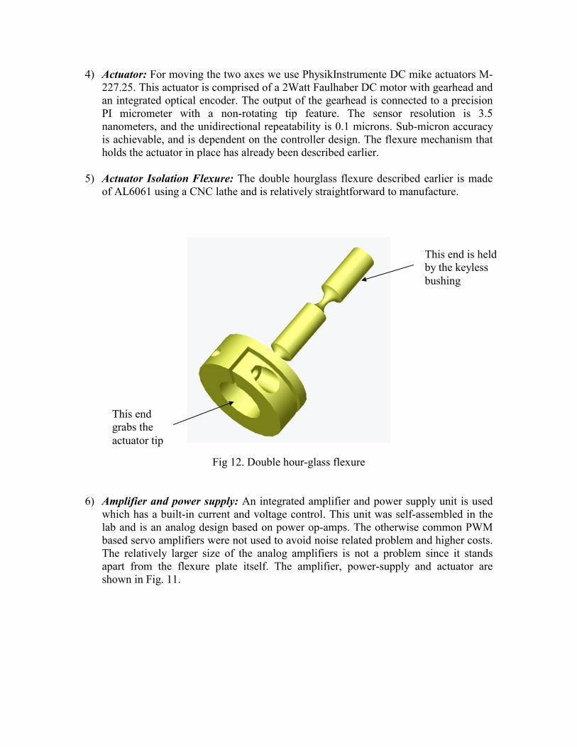
5) Actuator Isolation Flexure: The double hourglass flexure described earlier is made
of AL6061 using a CNC lathe and is relatively straightforward to manufacture.
Fig 12. Double hour-glass flexure 6) Amplifier and power supply: An integrated amplifier and power supply unit is used
which has a built-in current and voltage control. This unit was self-assembled in the lab and is an analog design based on power op-amps. The otherwise common PWM based servo amplifiers were not used to avoid noise related problem and higher costs. The relatively larger size of the analog amplifiers is not a problem since it stands apart from the flexure plate itself. The amplifier, power-supply and actuator are shown in Fig. 11.
This end grabs the actuator tip
This end is held by the keyless bushing
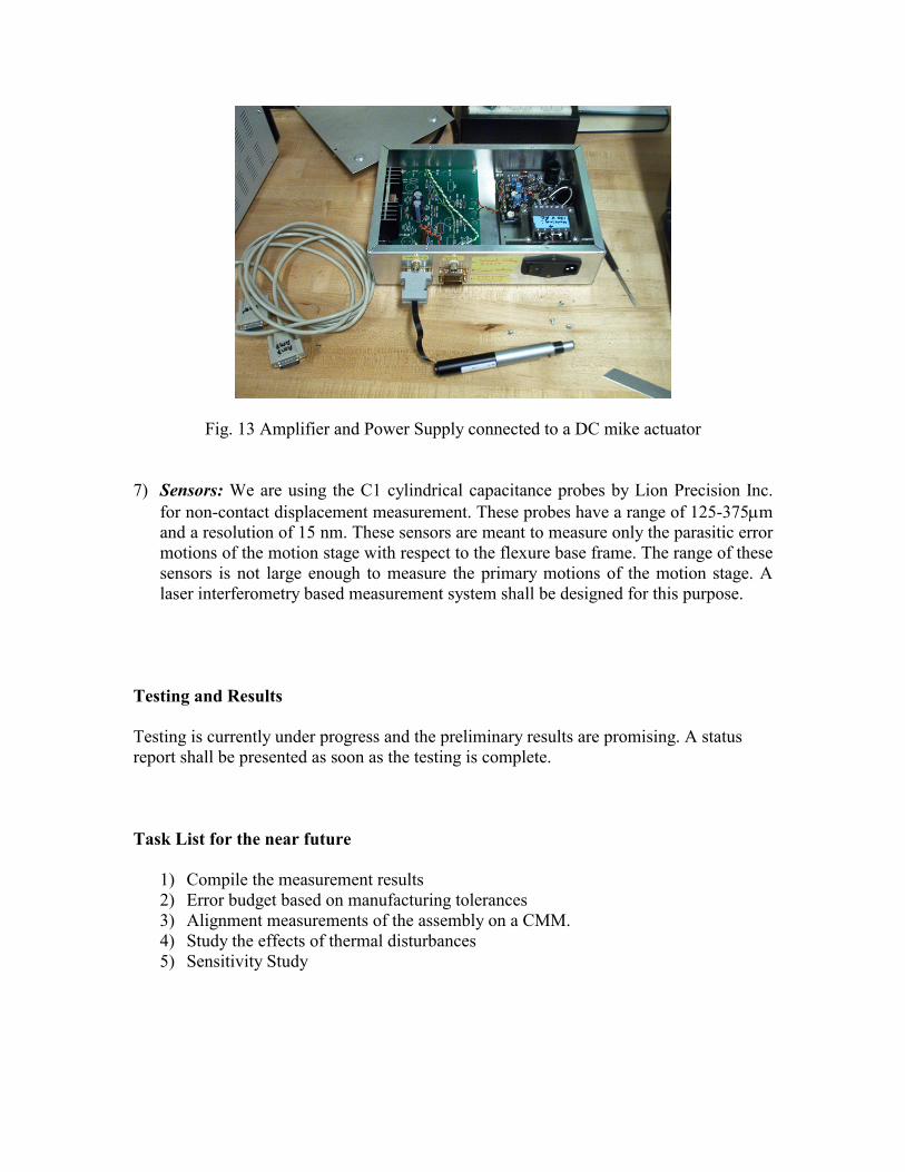
Fig. 13 Amplifier and Power Supply connected to a DC mike actuator
7) Sensors: We are using the C1 cylindrical capacitance probes by Lion Precision Inc. for non-contact displacement measurement. These probes have a range of 125-375µm and a resolution of 15 nm. These sensors are meant to measure only the parasitic error motions of the motion stage with respect to the flexure base frame. The range of these sensors is not large enough to measure the primary motions of the motion stage. A laser interferometry based measurement system shall be designed for this purpose.
Testing and Results Testing is currently under progress and the preliminary results are promising. A status report shall be presented as soon as the testing is complete. Task List for the near future
1) Compile the measurement results 2) Error budget based on manufacturing tolerances 3) Alignment measurements of the assembly on a CMM. 4) Study the effects of thermal disturbances 5) Sensitivity Study

APPENDIX A Machining Notes based on discussions with Andrew Gallant and Peter Morley at MIT's Central Machine Shop Shorya Awtar [email protected] 617-290-9569 Flexure Plate (see part drawing)
1. Determine the origin and axes based on some of the inner cuts. The location of origin and the alignment of axes is critical.
2. Machine holes on the motion stage that will hold the dowel pins to align the
reference block. All holes are positioned with respect to the above determined origin. (Location critical)
3. Machine holes on the outer base frame that will hold the dowel pins to align the
metrology plate. All holes are positioned with respect to the above determined origin.(Location Critical)
4. Machine the holes on the outer frame that will hold the pins that will support the
preload springs. (Location non-critical)
5. Skim the outer periphery of the plate to establish alignment of the outer edges with respect to the axes.
6. Flip the plate and machine the side holes. Location of these holes is critical. Use
the precision pins of Step 3 as references. The 19mm motor that will be held in these holes will be provided.
7. Flip the plate back to its flat configuration and remove the eight support tabs.
(Non-critical)
8. Drill and tap the holes for the tapered pipe plugs Metrology Plate (see part drawing)
1. Determine the origin and axes based on the inner edges of the square. The origin should nominally be in the center of the square hole but it does not have to be very precisely located. All critical dimensions and features will be machined after the origin has been selected.

2. Machine surfaces 1, 2 and 3: dimensional tolerance as well as surface flatness are critical. Only about two inch long segments of these surfaces close to the pin holes are critical.
3. Machine surfaces 4, 5 and 6 so that they are aligned with the axes. Alternately,
skim all the periphery of the plate. (Note: The plate will be waterjet cut 0.5mm oversize). In general, we would like to minimize machining to minimize the residual stress due to machining.
4. Machine the holes; only the inner two holes need to be precisely located.
5. Flip the part and machine the side holes. These holes can be referenced using the
pins on the front.
6. Drill and tap the holes for the tapered pipe plugs