Embed Size (px)
Citation preview

TIE - Technical Journal
Text DESCRIPTION:
Analysis of replaced CEMs indicates a high No Fault Found rate. To help identify the actual root
cause to certain electrical symptoms, this Tech Net Note is intended to clarify the role of the CEM in
the vehicle and in the CANbus system. The following Tech Net Note is meant to clear out some
confusion and hopefully reduce the number of CEMs being misdiagnosed. This information is
intended to supplement the information provided in VADIS Design and Function for the CEM, CANbus
fault-tracing and Software download.
SERVICE:
See attachment.
Volvo Car Corporation TIE - Technical Information Exchange
Title CEM Fault Tracing
Ref No US16352.1.2 en-GB Status Released
Issuer SWIECZOR - Stan Wieczorek Status Date 2010-03-03
Partner 3 US 7510 Volvo Cars North America Issue Date 2010-03-03
Func Group 3723 Func Desc electric distribution box; electric dist Reference
Attachment
File Name File Size
attachment 37-24.pdf 0.0139 MB
Vehicle Type
Type Eng Eng Desc Sales Body Gear Steer Model Year Plant Chassis range Struc Week Range
184 2005 -2006 0390000 -0446916 200425 -200609
275 2005 -2006 0134000 -0327999 200425 -200539
285 2005 -2006 0459000 -0554348 200425 -200539
295 2005 -2006 0220217 -0253999 200425 -200539
384 2005 -2006 0134000 -0254487 200425 -200539
CSC
Code Description
3L Repair information/Repair information/Not for warranty use
2V Software/Vehicle communication/Software/Vehicle communication/Not for warranty use
DTC
Control Module Code Fault Type
CEM DF03 Intermittent
CEM 1A51 Intermittent
CEM DF16 Intermittent
CEM 1A64 Intermittent
Page 1 of 1TIE - TJ
9/2/2010https://tie.vcc.ford.com/View_journal_listAction.do?dispatch=singlePrintJournal

TIE - Technical Journal
Text DESCRIPTION:
Analysis of replaced CEMs indicates a high No Fault Found rate. To help identify the actual root
cause to certain electrical symptoms, this Tech Net Note is intended to clarify the role of the CEM in
the vehicle and in the CANbus system. The following Tech Net Note is meant to clear out some
confusion and hopefully reduce the number of CEMs being misdiagnosed. This information is
intended to supplement the information provided in VADIS Design and Function for the CEM, CANbus
fault-tracing and Software download.
SERVICE:
See attachment.
Volvo Car Corporation TIE - Technical Information Exchange
Title CEM Fault Tracing
Ref No US16389.1.1 en-GB Status Released
Issuer CHINDER1 - Catherine Hinderman Status Date 2007-08-07
Partner 3 US 7510 Volvo Cars North America Issue Date 2007-06-19
Func Group 3724 Func Desc Reference
Attachment
File Name File Size
Attachment TJ 16389.doc.pdf 0.0139 MB
Vehicle Type
Type Eng Eng Desc Sales Body Gear Steer Model Year Plant Chassis range Struc Week Range
184 1999 -1999 0000580 -0063999 199815 -199850
285 2001 -2001 0026213 -0170999 200020 -200107
384 2001 -2001 0000148 -0092351 200032 -200107
CSC
DTC
Page 1 of 1TIE - TJ
8/31/2010https://tie.vcc.ford.com/View_journal_listAction.do?dispatch=singlePrintJournal

Copyright © 2007 Volvo Cars of North America, LLC. All rights reserved. Page 1 of 6
NO: 3x-xx DATE: MODEL: All P2X (S60 S80 V70 XC70 XC90) M. YEAR: 2005-2006 (structure week 200425-200545) CHASSIS: XC90 FC1 134000-256551 V70 FC1 459000-555060 S60 FC2 425000-522407 S80 FC1 390000-435423 XC70 FC1 173000-220845 V70 FC2 459000-554206 (FC = Factory code) 11th position of the VIN number SUBJECT: CEM harness terminal corrosion due to water entrance in plenum (Instruction for new harness installation) REFERENCE: VIDA repair instruction
This document supersedes the previous document dated 5/23/2006. Changes to this document are: Method 2 for later chassis numbers has been deleted due to the harness with the integrated grommet and plenum lid is no longer available. Method 1 shall be used for all chassis numbers in the header. Please update your records. DESCRIPTION:
Various electrical function and communication symptoms may occur in M/Y 2005-2006 vehicles caused by wet corrosion in the CEM connector. The grommet that seals the harness entrance to the Plenum box may not seal properly if it has been incorrectly assembled. This may cause a number of different functionality symptoms and DTC's to be set. Examples include but not limited to: - Headlight on, even if ignition key is taken out of ignition lock. - Warning messages in DIM display. - Warning lamps lit up. - Brake lights always on. - No start condition.
Tech-Net Notes “Fixed Right – First Time”
Volvo Technicians, Service and Parts Managers

Copyright © 2007 Volvo Cars of North America, LLC. All rights reserved. Page 2 of 6
PRODUCT MODIFICATION: A new plenum sealing strategy with integrated rubber grommet was introduced in production from 2005 week 45. See photo below. This new sealing strategy will be carried over to the replacement engine bay harnesses on the chassis numbers indicated, by modification of the replacement harness.
SERVICE: If there are signs of water penetration in plenum box and/or wet corrosion at the CEM connectors, it will be necessary to install a new CEM and replace the engine bay cable harness according to the method below:
Modification of the original type replacement harness Parts required;
• Engine bay cable harness, check VIDA parts catalogue (This is the original type engine bay harness which will be modified with the instruction below)
• Plenum lid, P/N 30728860
• Service grommet, P/N 30775689
• Cable tie, P/N P/N 983750 (2 required)
Modified replacement harness

Copyright © 2007 Volvo Cars of North America, LLC. All rights reserved. Page 3 of 6
1.
Removing the existing rubber grommet
Remove the old rubber grommet using a knife.
Caution! Make sure that no hoses or cables are damaged.
IMG-243942
2.
Remove and discard the holder from the new cable harness.
IMG-244520
3.

Copyright © 2007 Volvo Cars of North America, LLC. All rights reserved. Page 4 of 6
Remove and discard the existing surround.
Save the attachment screws to attach the new cover to the plenum floor.
IMG-243946
4.
Installing the new seal
Route the cable harness through the new rubber grommet and cover.
Caution! Exercise caution so that the rubber grommet is not damaged when the connectors are threaded through.
IMG-244521
5.
Installing the new seal, continued
Align the arrows (1) towards each other. Arrow (2) must point towards the handle on the rubber grommet.
IMG-243944
6.

Copyright © 2007 Volvo Cars of North America, LLC. All rights reserved. Page 5 of 6
Installing the cable ties
IMG-243945
7.
Installing the cover
Note: After installation, the cable harness under the cover will be slightly over length. Clamp it up in a suitable manner to prevent chaffing.
Tighten the screws to 10 Nm.
IMG-243947
WARRANTY CLAIM INFORMATION LABOR OP LABOR DESCRIPTION LABOR TIME 37349-2 Harness engine comp/dashboard repair See Note below Claims may be submitted under the new car warranty when there is a documented customer complaint using claim type: 01
Note: General Labor time based on technician time required for repair. This repair is subjected to all audit requirements outlined in the warranty Policy and Procedure manual.
VOLVO for life, Volvo Cars of North America, LLC Please circulate, read and initial: _____Svc Mgr _____ Parts Mgr _____Shop Foreman

Copyright © 2007 Volvo Cars of North America, LLC. All rights reserved. Page 6 of 6
_____ _____ _____ _____ _____ _____ _____ _____ _____ _____ _____ _____ TECHS _____ Warranty Administrator _____ _____ _____ _____ _____ _____ S. Advisors

TIE - Technical Journal
Text DESCRIPTION:
Various electrical function and communication symptoms may occur in M/Y
2005-2006 vehicles caused by wet corrosion in the CEM (Central Electrical Module)
connector. The grommet that seals the harness entrance to the Plenum box may not seal
properly if it has been incorrectly assembled.
Examples include but not limited to:
� Headlight on, even if ignition key is taken out of ignition lock.
� Warning messages in DIM (Driver's Information Module) display.
� Warning lamps lit up.
� Brake lights always on.
Volvo Car Corporation TIE - Technical Information Exchange
Title CEM harness terminal corrosion due to water entrance in plenum
Ref No US16409.1.4 en-GB Status Released
Issuer SWIECZOR - Stan Wieczorek Status Date 2008-05-28
Partner 3 US 7510 Volvo Cars North America Issue Date 2008-05-28
Func Group 3723 Func Desc electric distribution box; electric dist Reference
Attachment
File Name File Size
TNN_37-35v2.doc 0.2929 MB
Vehicle Type
Type Eng Eng Desc Sales Body Gear Steer Model Year Plant Chassis range Struc Week Range
184 2005 -2006 1 0390000 -0435423 200425 -200540
275 2005 -2006 1 0134000 -0256551 200425 -200540
285 2005 -2006 1 0459000 -0555060 200425 -200540
285 2005 -2006 2 0459000 -0554206 200425 -200540
295 2005 -2006 1 0173000 -0220845 200425 -200540
384 2005 -2006 2 0425000 -0522407 200425 -200540
CSC
Code Description
7B Starting/Engine does not start/Engine does not turn/No clicking sound at start attempt
AA Starting/Engine does not start/Engine turns
BE Starting/Engine does not start/Engine does not turn/Unsure when/at all times
BF Starting/Engine does not start/Engine does not turn/Clicking sound at start attempt
BJ Starting/Engine does not start/Unsure when/at all times
EY Headlights/Does not work
CI Tail light/Brake light does not work
7G Text window and warning symbol/Yellow symbol and text message
EA Text window and warning symbol/Red symbol and text message
FB Text window and warning symbol/Other problems
IV Text window and warning symbol/Text message
DTC
Page 1 of 2TIE - TJ
8/31/2010https://tie.vcc.ford.com/View_journal_listAction.do?dispatch=singlePrintJournal

� No start condition.
SERVICE:
See attachment.
Page 2 of 2TIE - TJ
8/31/2010https://tie.vcc.ford.com/View_journal_listAction.do?dispatch=singlePrintJournal

TIE - Technical Journal
Text * DESCRIPTION: Reports with the above listed CSC's has been received, stating that the brake
* light, headlight, horn or wiper may turn on by itself and remain on until a battery reset has
* been performed. Replacing the CEM has solved the symptom.
* PRODUCT MODIFICATION: To prevent the brake light from turning on by itself, a SW
* workaround solution has been introduced from structure week 200826- and chassis numbers;
* 275, 502892-
* 384, 724299-
* The software is backwards compatible to structure week 200425.
* The SW will shut off the output signal from CEM if it is incorrectly set to high. The SW will
* also add a diagnostic function and set DTC CEM-8D04 if this workaround solution has been
* activated.
* The permanent action to take care of the symptoms described above is to make the CEM
* more robust towards interference. This job is upstarted and planned to be introduced into
* production late quarter 4 2008.
* MATERIAL RETURN: Only after request in technical reports.
* TECHNICAL REPORT: Yes, please submit a vehicle report if the symptom of brake light turning
* on by itself would occur, even if the CEM is upgraded with the new software.
* SERVICE: If the symptom of brake light turning on by itself would occur, please order and
Volvo Car Corporation TIE - Technical Information Exchange
Title FTS: CEM may cause brake light, headlight, horn or wiper to turn on by itself.
Ref No US17082.5.0 en-GB Status Closed
Issuer SWIECZOR - Stan Wieczorek Status Date 2009-10-05
Partner 3 US 7510 Volvo Cars North America Issue Date 2008-07-09
Func Group 3723 Func Desc electric distribution box; electric dist Reference
Attachment
Vehicle Type
Type Eng Eng Desc Sales Body Gear Steer Model Year Plant Chassis range Struc Week Range
275 2007 -9999 21 0328000 -9999999 200620 -999999
285 2007 -2007 21 0617000 -0673859 200620 -200717
285 2007 -2008 22 0617000 -0693560 200620 -200739
295 2007 -2007 21 0254000 -0288671 200620 -200718
384 2007 -9999 22 0600000 -9999999 200620 -999999
CSC
Code Description
EY Headlights/Does not work
DB Tail light/Backup lights constantly lit
HI Horn/Does not work
JN Windshield wiper/Does not work
DTC
Page 1 of 2TIE - TJ
8/4/2010https://tie.vcc.ford.com/View_journal_listAction.do?dispatch=singlePrintJournal

* download the CEM Upgrade, P/N 30677017, to prevent this symptom from occurring.
* If any of the other symptoms would occur, please fault trace concerned cables and related
* components before any CEM may be replaced.
In urgent cases where a temporary solution is required, a battery disconnection for 10
minutes may solve the symptom, but it will probably return again.
VSTG OPERATION NUMBER:
36004-2 Software control module downloading
37206-2 Control module / relay box passenger compartment (CEM) replace
31116-2 Battery cable disconnect and reconnect
Page 2 of 2TIE - TJ
8/4/2010https://tie.vcc.ford.com/View_journal_listAction.do?dispatch=singlePrintJournal

VCNA TECHNICAL CONFERENCE APRIL 2005
VCNA CUSTOMER SERVICEUrban Dagerhorn & Stan Wieczorek, April 2005
Volvo Carsof North America, LLC.
Electrical??????????, ??????????, 20045
ELECTRICAL
APG, APRIL, 2005
URBAN DAGERHORN, STAN WIECZOREKROCKLEIGH, NJ, USA

VCNA TECHNICAL CONFERENCE APRIL 2005
VCNA CUSTOMER SERVICEUrban Dagerhorn & Stan Wieczorek, April 2005
Volvo Carsof North America, LLC.
F.GROUP: 3729 VARIANT, M/Y : P2X, MY 2005TJ REF : 8529
TITLE: Electrical function and communication symptom due to water entrance at Plenum boxCONDITION: : Various electrical function and communication symptoms may occur in M/Y 2005 vehicles caused by wet corrosion in the CEM connector, if water has penetrated through the plenum box by the sealing grommet.The grommet that seals the cables to the CEM may not seal good enough, if it has been incorrectly assembled.This may cause a number of different functionality symptoms and DTC's to be set.Examples:
–Headlights and/or Brake light is on, even if ignition key is taken out of ignition lock. –Warning messages in DIM display.–Warning lamps lit up.–Engines run w/ key out of ignition–Engine stalls–Battery flat–Climate sys fan on all the time–Frt. Park lights stuck on

VCNA TECHNICAL CONFERENCE APRIL 2005
VCNA CUSTOMER SERVICEUrban Dagerhorn & Stan Wieczorek, April 2005
Volvo Carsof North America, LLC.
F.GROUP: 3729 VARIANT, M/Y : P2X, MY 2005TJ REF : 8529
TITLE: Electrical function and communication symptom due to water entrance at Plenum box, cont.
PRODUCTION SOLUTION: A new designed plenum box lid is being developed.Planned for introduction into production during Q2/ 2006.
SERVICE SOLUTION:Locate and correct the water leakage according to TJ 8529.

VCNA TECHNICAL CONFERENCE APRIL 2005
VCNA CUSTOMER SERVICEUrban Dagerhorn & Stan Wieczorek, April 2005
Volvo Carsof North America, LLC.

VCNA TECHNICAL CONFERENCE APRIL 2005
VCNA CUSTOMER SERVICEUrban Dagerhorn & Stan Wieczorek, April 2005
Volvo Carsof North America, LLC.

Volvo Technical Conference in Brunswick March 2006, FG3
Page 1Issue date: Mar-09-2006,
ELECTRICALBRUNSWICK, GA
MARCH 2006
URBAN DAGERHORN, STAN WIECZOREK & PÄR NILSSONROCKLEIGH, NJ, USA

Volvo Technical Conference in Brunswick March 2006, FG3
Page 2Issue date: Mar-09-2006,
F.GROUP: 3726 VARIANT, M/Y: P2X, MY 05 and 06 up to W539
TJ REF : 8529
TITLE: CEM harness, Water entrance through plenum
CONDITION:Water entrance through plenum cover corroding the CEM harness Terminals.
PRODUCTION SOLUTION: Harness with integrated lid/Plenum cover introduced W540
SERVICE SOLUTION; Harness with integrated lid can be used on cars from W520 to W540 with 2 exceptions “NM” and “S” harness. These 2 can be used on cars back to W446.
Refer to lazy dog on your memory sticks.
Production solution and Harness supercession
NOTE! If there is any evidence of moisture In the CEM connectors, the harnessMust be replaced. The terminals will Eventually be compromised

Volvo Technical Conference in Brunswick March 2006, FG3
Page 3Issue date: Mar-09-2006,
ENGINE BAY HARNESS P28 05:40 P28 05:40 P2X 05:40
Ny Plenumgenomföring 0540 > 0520 0540 > 0520 0540 > 0520LABEL 20V8 P28 non V8 KB
Man. Petrol, DSTC J 30739748 > 30737530Man. Petrol, ABS/STC K 30739749 > 30737531Man. Petrol, DSTC, ECPS,Vacc,CCD,GDL R 30739750 > 30737532
Man. Diesel, DSTC, ECPS,GDL C 30739751 > 30737533Man. Diesel, ABS/STC, ECPS,GDL A 30739752 > 30737534Aut. Petrol, DSTC L 30739753 > 30737535Aut. Petrol, ABS/STC M 30739754 > 30737536Aut. Petrol, DSTC, ECPS,Vacc,CCD,GDL T 30739755 > 30737537 - " - R-line U 30739756 > 30737538Aut. Diesel, DSTC, ECPS,GDL D 30739757 > 30737539Aut. Diesel, ABS/STC, ECPS,GDL B 30739758 > 30737540
Man. Petrol, DSTC, ECPS,Vacc,GDL NJ 30739746 > 30739353 30739759 > 30737541Man. Petrol, ABS/STC, ECPS,Vacc,GDL NK 30739760 > 30737542Aut. Petrol, DSTC, ECPS,Vacc,GDL NL 30739825 > 30667342 30739761 > 30737543Aut. Petrol, ABS/STC, ECPS,Vacc,GDL NM 30667342 back to 0446 30739762 > 30737544Man. Bi-fuel, DSTC, ECPS,GDL E 30739763 > 30737545Man. Bi-fuel, ABS/STC, ECPS,GDL F 30739764 > 30737546Aut. Bi-fuel, DSTC, ECPS,GDL G 30739765 > 30737547Aut. Bi-fuel, ABS/STC, ECPS,GDL H 30739766 > 30737548Man, Diesel, DSTC, ECPS, GDL, CCD NC 30739767 > 30737549Aut, Diesel, DSTC, ECPS, GDL, CCD ND 30739768 > 30737550Aut. Petrol, DSTC, ECPS,Vacc,CCD,GDL,6cyl Y 30739769 > 30737551Aut. Petrol, DSTC, ECPS,Vacc,GDL,6cyl V 30739826 > 30667343 30739770 > 30737552Aut. Petrol, ABS/STC, ECPS,Vacc,GDL,6cyl S 30667343 back to 0446 30739771 > 30737553V8 NA 30739745 > 30739344

Volvo Technical Conference in Brunswick March 2006, FG3
Page 4Issue date: Mar-09-2006,
P2X CEM harness Service grommetFor cars from start of production MY 2005 up to W520 you must use the original P/N harness as well as a
service grommet P/N 30775689 and a plenum lid P/N 30728860.The grommet will be removed from the new harness and replaced with the service grommet and lid.
Preliminary service instructions are on your memory sticks
NOTE! If there is any evidence of moisture In the CEM connectors, the harnessMust be replaced. The terminals will Eventually be compromised

TC Rockleigh NJ / VCNA / Wieczorek, Bodmar
Page 1Issue date: 24 June 2008, Security Class: Proprietary
ELECTRICALRockleigh NJJune 2008
MAGNUS BODMAR & STAN WIECZOREK ROCKLEIGH, NJ, USA

TC Rockleigh NJ / VCNA / Wieczorek, Bodmar
Page 2Issue date: 24 June 2008, Security Class: Proprietary
F.GROUP: 3723 VARIANT, M/Y: P2X MY 2007 -TJ REF : 17082TITLE: CEM may cause brake light to turn on by itselfDESCRIPTION: We have received reports stating that the brake light, headlight, horn or
wiper may turn on by itself and remain on until a battery reset has been performed. Replacing the CEM has solved the symptom.
SERVICE:A SW workaround that will shut off the output signal from CEM if it is incorrectly set to high, is under development. This SW is scheduled to be released 08w26. The SW will also add a diagnostic function and set a DTC if this workaround solution has been activated.
DTC CEM-8D03, if this is observed with the complaints about brake lights being on. Replace CEM.

TC Rockleigh NJ / VCNA / Wieczorek, Bodmar
Page 3Issue date: 24 June 2008, Security Class: Proprietary
F.GROUP: 3723 VARIANT, P2X M/Y: 2005 2006TJ REF : 8529TITLE: New repair method for corroded CEM connectors DESCRIPTION: In the past we have replaced the Engine harness if water ingress has damaged the connector at the CEM.
METHOD MODIFICATION:Extensions with assembled connectors will be spliced into the engine harness instead of replacing the entire harness
TNN will be updated after method verification.

§ Volvo Car Customer Service
TJ Instruction
No. T9159
Date
June -08 Issue 01
Title Connector replacement Page
1 of 4
Model S80 (-06), V70 (00-08), XC70 (-07),S60, XC90
Model Year 2005-2006
Competence requirement
Volvo Level 3E Technician
Material Quantity Part No.
Extension cable (32 pin) 1 31270635*
Extension cable (36 pin) 1 31270634*
* Only if necessary
1.
Explanation
To prevent having to replace the entire engine compartment cable harness in the event of water penetrating the central control module (CEM), 2 different types of extension cables have been introduced.
(1) Extension cable, 32 pin
(2) Extension cable, 36 pin
IMG-277370

Instruction T9159 Page 2 of 4
2.
Replacement of the 32 pin connector
Remove the secondary catch.
IMG-277371
3.
32-pin connector
Caution! Cut and splice one cable at a time.
For cable splicing see:
Removal, replacement and installation Electrical system Cables and fuses Wiring
Caution! The splice is designed to fit all variants, which means that colors and num-ber of cables do not always correspond. Always start from the location of the terminals in the vehicle's connector at the cable splice.
Caution! If one or several of the cables remain, it/they must be removed or a moisture proof splice must be installed in the end of the cable(s).
Install the secondary catch.
IMG-277372

TJ Instruction T9159 Page 3 of 4
4.
Replacement of the 36 pin connector
Remove the secondary catch.
IMG-277373
5.
36 pin connector
Caution! Cut and splice one cable at a time.
For cable splicing see:
Removal, replacement and installation Electrical system Cables and fuses Wiring
Caution! The splice is designed to fit all variants, which means that colors and num-ber of cables do not always correspond. Always start from the location of the terminals in the vehicle's connector at the cable splice.
Caution! If one or several of the cables remain, it/they must be removed or a moisture proof splice must be installed in the end of the cable(s).
Install the secondary catch.
IMG-277374

Instruction T9159 Page 4 of 4
6.
IMG-294644


§ Volvo Car Customer Service
TJ Instruction
No. T9158
Date
June -08 Issue 01
Title Replacement of the plenum cover Page
1 of 7
Model S80 (-06), V70 (00-08), XC70 (-07),S60, XC90
Model Year 2005-2006
Competence requirement
Volvo Level 3E Technician
Material Quantity Part No.
Seal RHD 1 30728861
Seal LHD 1 30728860
Rubber grommet 1 30775689
Cable tie 2 983750
Central electronic module (CEM) 1 30786890*
CEM reload S80 1 9438273*
CEM reload V70/XC70 1 9494722*
CEM reload S60 1 8645433*
CEM reload XC90 1 8691290*
* Only if necessary
1.
Note! Some variation in the illustrations may occur, but the essential information is always correct.

Instruction T9158 Page 2 of 7
2.
Remove the battery's minus cable, see:
Removal, replacement and installation Electrical system Battery and mounting Battery
Remove the wiper mechanism, see:
Removal, replacement and installation Electrical system Other electrical equipment Cleaner
3.
IMG-277365
4.

TJ Instruction T9158 Page 3 of 7
5.
Checking the connector
Check that there is no oxidation in any of the upper connectors on the CEM. If there is oxidation, the CEM must be replaced at the same time as replacing any affected connectors.
For CEM replacement, see:
Removal, replacement and installation Electrical system Cables and fuses Central electrical unit and fuse box.
To replace the connector, see Instruction T9159, Connector replacement.
IMG-277367
6.
IMG-277368

Instruction T9158 Page 4 of 7
7.
Release the engine bay wiring harness, under the dashboard.
Route the wiring harness in the plenum channel.
8.
Removal of the existing rubber grommet
Caution! Do not damage any wirings.
Remove the old rubber grommet using a knife.
IMG-243942
9.
Remove the holder from the wiring harness.
IMG-244520

TJ Instruction T9158 Page 5 of 7
10.
Removal of border
IMG-243946
11.
IMG-243943

Instruction T9158 Page 6 of 7
12.
Installation of the new seal
Caution! Do not damage the rubber grommet when routing the connector through.
Route the wiring harness through the new rubber grommet and cover.
IMG-244521
13.
Position the arrows (1) opposite each other. Arrow (2) must point towards the handle on the rubber grommet.
IMG-243944

TJ Instruction T9158 Page 7 of 7
14.
Installation of the cable ties
IMG-243945
15.
Installation of the cover
Caution! Ensure that the rubber gaskets remain in place on the four screws.
Note! After replacement, there will be some wiring harness excess. Secure in a suitable location.
Tighten to 10 Nm.
To install, reverse the removal procedure.
IMG-243947

TIE - Technical Journal
Text * TJ instruction attachments "T9158EN01.doc" and "T9159EN01.doc" changed in headers.
DESCRIPTION: Electrical function and communication symptoms may occur in M/Y 2005-2006
vehicles caused by wet corrosion in the CEM connector, if water has penetrated through the
plenum box via the sealing grommet.
The grommet that seals the cables to the CEM may not seal good enough, if it has been
incorrectly assembled.
This may cause different functionality symptoms and DTC's to be set.
Examples:
- Headlight on, even if ignition key is taken out of ignition lock.
- Warning messages in DIM display.
- Brake lights always on while parked.
- No start condition.
PRODUCT MODIFICATION: A new plenum box (see picture, New plenum box 2005w40-)
with integrated rubber grommet was introduced in VCC production from 2005 week 40.
Volvo Car Corporation TIE - Technical Information Exchange
Title Electrical function and communication symptom in M/Y 2005-2006, water in CEM
Ref No US8529.17.0 en-GB Status Released
Issuer SWIECZOR - Stan Wieczorek Status Date 2008-06-09
Partner 3 US 7510 Volvo Cars North America Issue Date 2008-06-09
Func Group 3729 Func Desc miscellaneous Reference Q2-060322
Attachment
File Name File Size
T9158EN01.doc 0.4628 MB
T9159EN01.doc 0.5078 MB
Rubber gasket.JPG 0.0210 MB
New plenum box 2005w40-.JPG 0.0254 MB
Vehicle Type
Type Eng Eng Desc Sales Body Gear Steer Model Year Plant Chassis range Struc Week Range
184 2005 -2006 21 0390000 -0435423 200425 -200540
275 2005 -2006 21 0134000 -0256551 200425 -200540
285 2005 -2006 21 0459000 -0555060 200425 -200540
285 2005 -2006 22 0459000 -0554206 200425 -200540
295 2005 -2006 21 0173000 -0220845 200425 -200540
384 2005 -2006 22 0425000 -0522407 200425 -200540
CSC
Code Description
BJ Starting/Engine does not start/Unsure when/at all times
EY Headlights/Does not work
CI Tail light/Brake light does not work
IV Text window and warning symbol/Text message
DTC
Page 1 of 2TIE - TJ
9/3/2010https://tie.vcc.ford.com/View_journal_listAction.do?dispatch=singlePrintJournal

See end chassis break points in TJ header.
MATERIAL RETURN: If requested in vehicle report.
TECHNICAL REPORT: Yes, please submit a report if there are signs of water ingress after the
chassis break points in TJ header.
SERVICE: If there are signs of water penetration in plenum box and / or wet corrosion at CEM
connectors, it is necessary to:
- Replace the plenum cover in S60/V70/XC70/S80, cars between 2004w25-2005w20,
See instruction T9158.
- Replace the plenum cover in XC90, cars between 2004w25-2004w45,
See instruction T9158.
- Replace engine bay connectors and terminals with extension cables. See instruction T9159.
- replace CEM (according to VIDA).
NOTE! See instruction T9158, operation 15 and caution text. Both steel washer and rubber
gasket must be moved over to the new cover. See attached picture, Rubber gasket.JPG
PARTS: See attached instructions T9158 and T9159.
VSTG OPERATION NUMBER:
99376-2 Rubber seal cable harness engine, replace
37206-2 CEM, replace
36004-2 Software control module downloading
Page 2 of 2TIE - TJ
9/3/2010https://tie.vcc.ford.com/View_journal_listAction.do?dispatch=singlePrintJournal

NO: 37-24DATE: 10-22-2002MODEL: MY 99 – S80, MY 01 – S60, V70 and V70 XCSUBJECT: CEM Fault TracingREFERENCE: Tech Note 37-18, 37-22, 34-05, 36-35
THIS TECH NOTE SUPERCEDES THE PREVIOUS 37-24 DATED 10-21-2002.PLEASE UPDATE YOUR FILES.
DESCRIPTION:Analysis of replaced CEMs indicates a high No Fault Found rate. To help identify the actual rootcause to certain electrical symptoms, this Tech Net Note is intended to clarify the role of the CEM inthe vehicle and in the CANbus system. The following Tech Net Note is meant to clear out someconfusion and hopefully reduce the number of CEMs being misdiagnosed. This information isintended to supplement the information provided in VADIS Design and Function for the CEM, CANbusfault-tracing and Software download.
NOTE: The CEM contains vehicle specific information which cannot be erased once programmed;once a CEM is programmed, it can not be used in another vehicle. Therefore, a CEM should not beprogrammed to a vehicle for fault tracing. Don't condemn the CEM.
SERVICE:Common misunderstandings:
CANbus Faults:"Do not shoot the messenger." Although the CEM monitors CANbus communication and verifies thepresents of the other nodes, it is not responsible for all CANbus activity. When CANbus related faultsare posted in the CEM, there seem to be a misunderstanding that the CEM is faulty. The CEM hasways of identifying faults in other nodes or in cable harness. When the CANbus is active, the CEM ischecking for specific signals from each of the nodes (control units). Typically DTC CEM 1A51-1A64indicates the CEM has not received the normal CAN message from the specific node, see Tech NetNote 37-22. DTC CEM DF03 – DF16 point towards short circuits from the CANbus wires (green andwhite twisted pair) to ground or +. This does NOT mean that the CEM is faulty, the CEM has detectedthat there is a fault somewhere in the vehicle.
Battery drain:When fault tracing a vehicle for battery drain or dead battery, components with direct battery feedshould be checked. For example: Does a light stay on?, does the power stage for the passengercompartment fan draw current after the key is out of the ignition? is the side mirror heater onconstantly? is a relay activated all the time? (this is only a few examples, the wiring schematic for thespecific vehicle being fault traced should be used for additional possibilities)
PAGE 1 of 3
Tech-Net Notes“Fixed Right – First Time”
Volvo Technicians, Service and Parts Managers

SW download:The SW download procedure for CEM in VADIS is clarified in Tech Net Note 37-18, andmust be used when replacing or programming a CEM. A SW download failing does notbreak any nodes. It may be difficult to recover, but it is possible (See Tech Net Note 34-05).
Immobilizing:Immobilizer related problems are rarely due to a faulty CEM hardware. See Tech Net Note36-35 for proper immobilizer fault tracing.
Faulty relay activation:Some CEMs are replaced when it is only the relay that is faulty. Relays are very easy toreplace and test in another position, or another car. Often if a CEM is misdiagnosed due to afaulty relay, the faulty relay may then be installed into another position when the CEM isreplaced. This will give the impression that: (1) the original CEM was defective; and (2) thenew CEM has a different defect.
The CEM power feed relays should give a very straightforward fault tracing. If for examplethere are codes 1A54, PSM not alive, 1A55 CCM not alive, and 1A56 DIM not alive, it isimportant to check the relay 2/29, extended X feed.
Some tips and hints:• The CEM monitoring function in VADIS is a very useful tool to determine if a relay is
pulled or an input is detected as low or high. This monitor function, together with anactual measurement with the breakout box, will solve many questions regarding whetheror not the CEM is operating correctly. Note only the CEM relay coil is diagnosed, not theactual relay output.
• When fault tracing CANbus related DTCs, refer to the "Data Communication" pages in theappropriate wiring diagram. These pages provide critical information including whichnodes are connected in series and which are connected in parallel.
• CEM contains PIN codes related to immobilizer function but has got NOTHING to do withremote key PIN codes, or memory for power seat or memory mirrors. (remote codes arestored in UEM, seat memory in PSM, and mirror memories in DDM and PDMrespectively.)
• The starter motor relay, which is activated by the CEM, has 0V output from the CEM bothin activated and non activated state. Do not rule out any possibilities based on thevoltage only. Check if the relay clicks or use a test lamp if available. The 0V ”supplied”by the CEM in the non activated state will not energize a relay coil.
• The CEM monitors the CAN high (white) and CAN low (green) cables. This does NOTmean that any CANbus problems are CEM related. The likelihood that the CEM causes aDTC E001 code is not higher than that another node does it. When fault tracing CANbusrelated fault codes in the CEM and other nodes, measure CANbus resistance (See TNN37-22). Check behind radio for a pinched wire, check the CANbus wiring to the SRS,TCM, and ECM, including terminal tension.
PAGE 2 of 3

CAUTION: When checking terminal tension, take care not to damage the female terminal byprobing with a test lead or paper clip. Male terminal, part number 9441394 (the femalecounter part is part number 9442486) can be used to safely check for proper terminal tensionin the applicable connectors.
• NOTE: If a DTC E001 is permanent in any node and the cable harness is OK, a good tipis to depower all nodes having DTC E001 in them (except the CEM) and see if the codedisappears. Then reinstall them one by one until the code reappears. If it is possible tocommunicate with the vehicle in ignition pos 0 and 1 but not in 2, look for a 15 fed nodecorrupting the CANbus.
• To galvanically separate the OBDII connector from the rest of the vehicle’s CANbus, theCEM contains 4 diagnostic relays. This means that the CEM ”opens” communication HWwise to both high speed and low speed. The command to open this communication issent via K-line from the VADIS cart to the CEM. This means that if VADIS cancommunicate to at least one node in the low speed and one node in the high speed CANnet, then these diagnostic relays are functioning properly. A broken K-line communication(between VADIS and the CEM) would disable both CAN nets. For cases in which there isno communication from VADIS to the vehicle (and the vehicle is function properly), verifythe proper functionality of the VCT2000 cable.
• CEM is involved in the alarm system but so are other nodes. For vehicles after MY01,VADIS can be used to determine what triggered the alarm. Verify proper functionality ofdoor locks, PDM, DDM, and UEM, for example by using the monitor function in vehiclecommunication in VADIS.
• Note! there is a big difference between “there is no DTC:s in a node” and “the node doesnot report a DTC”. When reading DTC:s from all nodes, and there is a permanentCANbus fault, the VADIS information can be misinterpreted. If a node is not listed, it doesnot necessarily mean that the node contains no DTC, it can mean that the node is notresponding.
• The CEM only communicates the temperature on a serial link to the TCU (seat heatercontrol unit). If this serial link has good voltage levels when high and low, the CEM is NOTlikely to be the root cause for a seat heater problem.
VOLVO for life,Volvo Cars of North America, LLC.Technical Service
Please read, initial and circulate:
____Svc Mgr ____ Parts Mgr ____ ____ ____ ____ ____ ____ ____ ____ ____ TECHS
____Wty Administrator _____Shop Foreman
PAGE 3 of 3

�
�
�
�
�
�
�
�
�
NO: 32-04 DATE: 12-14-2005 MODEL: S60, S80, V70, XC70, XC90 (excl. V8) M. YEAR: 2005 & 2006 SUBJECT: CEM DTC DD21 due to faulty LIN-network, Alternator Not Charging REFERENCE: VIDA
DESCRIPTION: DTC CEM-DD21 may be set because of faulty communication between the Alternator and CEM due to the installation of extra LIN wiring for the upcoming BLIS, (Blind Spot Information System). Customers may also report an intermittent DIM message "POWER SYSTEM SERVICE REQUIRED" It may be possible that there is a pinched LIN-bus wire from the CEM to the BLIS-system between A-pillar body and the dashboard assembly on the left side. See details below under "SERVICE". PRODUCT MODIFICATION: A clip has been installed on the cars to prevent the LIN wire being pinched in production. SERVICE: Although BLIS (BLind spot Information System) has not been introduced yet, vehicles are pre-wired in production. The cables from CEM to RCM (Right Camera Module) and LCM (Left Camera Module) are present up to the mirror connector in both front doors. The LIN-bus is also connected internally inside the CEM (see updated wiring diagram). When fault tracing a CEM-DD21, please assure that the RCM and LCM circuits are not overlooked. The BLIS circuits are not indicated in the Wiring Diagram for MY2005, but have been corrected for MY2006. BLIS = Blind Spot Information System ACM = Alternator Control Module LCM = Left-hand Camera Module RCM = Right-hand Camera Module CEM = Central Electrical Module LIN = Local interconnect network
Tech-Net Notes “Fixed Right – First Time”
Volvo Technicians, Service and Parts Managers

If there is a short to ground in the circuit from CEM D24, repair the affected wiring as necessary. If the DTC CEM-DD21 remains, perform normal fault tracing for the DTC per VIDA instruction.
A short to ground in this LIN circuit leg will affect the ACM

WARRANTY CLAIM INFORMATION LABOR OP LABOR DESCRIPTION LABOR TIME 03740 Checking cables for DTC CEM DD 21 0.3 hr 37419 General op for repairing cables ------- (Claimed time must be substantiated) Claims may be submitted under the new car warranty when there is a documented customer complaint using claim type: 01
VOLVO for life, Volvo Cars of North America, LLC Technical Service Please circulate, read and initial: _____Svc Mgr _____ Parts Mgr _____Shop Foreman _____ _____ _____ _____ _____ _____ _____ _____ _____ _____ _____ _____ TECHS _____ Warranty Administrator _____ _____ _____ _____ _____ _____S. Advisors

NO: 37-24DATE: 10-22-2002MODEL: MY 99 – S80, MY 01 – S60, V70 and V70 XCSUBJECT: CEM Fault TracingREFERENCE: Tech Note 37-18, 37-22, 34-05, 36-35
THIS TECH NOTE SUPERCEDES THE PREVIOUS 37-24 DATED 10-21-2002.PLEASE UPDATE YOUR FILES.
DESCRIPTION:Analysis of replaced CEMs indicates a high No Fault Found rate. To help identify the actual rootcause to certain electrical symptoms, this Tech Net Note is intended to clarify the role of the CEM inthe vehicle and in the CANbus system. The following Tech Net Note is meant to clear out someconfusion and hopefully reduce the number of CEMs being misdiagnosed. This information isintended to supplement the information provided in VADIS Design and Function for the CEM, CANbusfault-tracing and Software download.
NOTE: The CEM contains vehicle specific information which cannot be erased once programmed;once a CEM is programmed, it can not be used in another vehicle. Therefore, a CEM should not beprogrammed to a vehicle for fault tracing. Don't condemn the CEM.
SERVICE:Common misunderstandings:
CANbus Faults:"Do not shoot the messenger." Although the CEM monitors CANbus communication and verifies thepresents of the other nodes, it is not responsible for all CANbus activity. When CANbus related faultsare posted in the CEM, there seem to be a misunderstanding that the CEM is faulty. The CEM hasways of identifying faults in other nodes or in cable harness. When the CANbus is active, the CEM ischecking for specific signals from each of the nodes (control units). Typically DTC CEM 1A51-1A64indicates the CEM has not received the normal CAN message from the specific node, see Tech NetNote 37-22. DTC CEM DF03 – DF16 point towards short circuits from the CANbus wires (green andwhite twisted pair) to ground or +. This does NOT mean that the CEM is faulty, the CEM has detectedthat there is a fault somewhere in the vehicle.
Battery drain:When fault tracing a vehicle for battery drain or dead battery, components with direct battery feedshould be checked. For example: Does a light stay on?, does the power stage for the passengercompartment fan draw current after the key is out of the ignition? is the side mirror heater onconstantly? is a relay activated all the time? (this is only a few examples, the wiring schematic for thespecific vehicle being fault traced should be used for additional possibilities)
PAGE 1 of 3
Tech-Net Notes“Fixed Right – First Time”
Volvo Technicians, Service and Parts Managers

SW download:The SW download procedure for CEM in VADIS is clarified in Tech Net Note 37-18, andmust be used when replacing or programming a CEM. A SW download failing does notbreak any nodes. It may be difficult to recover, but it is possible (See Tech Net Note 34-05).
Immobilizing:Immobilizer related problems are rarely due to a faulty CEM hardware. See Tech Net Note36-35 for proper immobilizer fault tracing.
Faulty relay activation:Some CEMs are replaced when it is only the relay that is faulty. Relays are very easy toreplace and test in another position, or another car. Often if a CEM is misdiagnosed due to afaulty relay, the faulty relay may then be installed into another position when the CEM isreplaced. This will give the impression that: (1) the original CEM was defective; and (2) thenew CEM has a different defect.
The CEM power feed relays should give a very straightforward fault tracing. If for examplethere are codes 1A54, PSM not alive, 1A55 CCM not alive, and 1A56 DIM not alive, it isimportant to check the relay 2/29, extended X feed.
Some tips and hints:• The CEM monitoring function in VADIS is a very useful tool to determine if a relay is
pulled or an input is detected as low or high. This monitor function, together with anactual measurement with the breakout box, will solve many questions regarding whetheror not the CEM is operating correctly. Note only the CEM relay coil is diagnosed, not theactual relay output.
• When fault tracing CANbus related DTCs, refer to the "Data Communication" pages in theappropriate wiring diagram. These pages provide critical information including whichnodes are connected in series and which are connected in parallel.
• CEM contains PIN codes related to immobilizer function but has got NOTHING to do withremote key PIN codes, or memory for power seat or memory mirrors. (remote codes arestored in UEM, seat memory in PSM, and mirror memories in DDM and PDMrespectively.)
• The starter motor relay, which is activated by the CEM, has 0V output from the CEM bothin activated and non activated state. Do not rule out any possibilities based on thevoltage only. Check if the relay clicks or use a test lamp if available. The 0V ”supplied”by the CEM in the non activated state will not energize a relay coil.
• The CEM monitors the CAN high (white) and CAN low (green) cables. This does NOTmean that any CANbus problems are CEM related. The likelihood that the CEM causes aDTC E001 code is not higher than that another node does it. When fault tracing CANbusrelated fault codes in the CEM and other nodes, measure CANbus resistance (See TNN37-22). Check behind radio for a pinched wire, check the CANbus wiring to the SRS,TCM, and ECM, including terminal tension.
PAGE 2 of 3

CAUTION: When checking terminal tension, take care not to damage the female terminal byprobing with a test lead or paper clip. Male terminal, part number 9441394 (the femalecounter part is part number 9442486) can be used to safely check for proper terminal tensionin the applicable connectors.
• NOTE: If a DTC E001 is permanent in any node and the cable harness is OK, a good tipis to depower all nodes having DTC E001 in them (except the CEM) and see if the codedisappears. Then reinstall them one by one until the code reappears. If it is possible tocommunicate with the vehicle in ignition pos 0 and 1 but not in 2, look for a 15 fed nodecorrupting the CANbus.
• To galvanically separate the OBDII connector from the rest of the vehicle’s CANbus, theCEM contains 4 diagnostic relays. This means that the CEM ”opens” communication HWwise to both high speed and low speed. The command to open this communication issent via K-line from the VADIS cart to the CEM. This means that if VADIS cancommunicate to at least one node in the low speed and one node in the high speed CANnet, then these diagnostic relays are functioning properly. A broken K-line communication(between VADIS and the CEM) would disable both CAN nets. For cases in which there isno communication from VADIS to the vehicle (and the vehicle is function properly), verifythe proper functionality of the VCT2000 cable.
• CEM is involved in the alarm system but so are other nodes. For vehicles after MY01,VADIS can be used to determine what triggered the alarm. Verify proper functionality ofdoor locks, PDM, DDM, and UEM, for example by using the monitor function in vehiclecommunication in VADIS.
• Note! there is a big difference between “there is no DTC:s in a node” and “the node doesnot report a DTC”. When reading DTC:s from all nodes, and there is a permanentCANbus fault, the VADIS information can be misinterpreted. If a node is not listed, it doesnot necessarily mean that the node contains no DTC, it can mean that the node is notresponding.
• The CEM only communicates the temperature on a serial link to the TCU (seat heatercontrol unit). If this serial link has good voltage levels when high and low, the CEM is NOTlikely to be the root cause for a seat heater problem.
VOLVO for life,Volvo Cars of North America, LLC.Technical Service
Please read, initial and circulate:
____Svc Mgr ____ Parts Mgr ____ ____ ____ ____ ____ ____ ____ ____ ____ TECHS
____Wty Administrator _____Shop Foreman
PAGE 3 of 3

Tech Update - Rockleigh / E-meeting Andy McCloskey - Martin Hansson
Page 1Issue date: 2009-3-18 Security Class: Proprietary
BODY AND INTERIORMarch 2009 Technical Update
Andy McCloskey - Martin HanssonE-Meeting

Tech Update - Rockleigh / E-meeting Andy McCloskey - Martin Hansson
Page 2Issue date: 2009-3-18 Security Class: Proprietary
All Models Sunroof, water leakage due to shrunk hoses.Analyze of returned parts from California confirms the statements from the TRs.Hoses with new material will be introduced 09W15.

VCNA TECHNICAL CONFERENCE APRIL 2005
VCNA CUSTOMER SERVICEName responsible, April 2005 Volvo Carsof North America, LLC.
BODY AND TRIM
APG, APRIL, 2005
MARK VAN EXE / JOHAN TAWSROCKLEIGH, NJ, USA

VCNA TECHNICAL CONFERENCE APRIL 2005
VCNA CUSTOMER SERVICEName responsible, April 2005 Volvo Carsof North America, LLC.
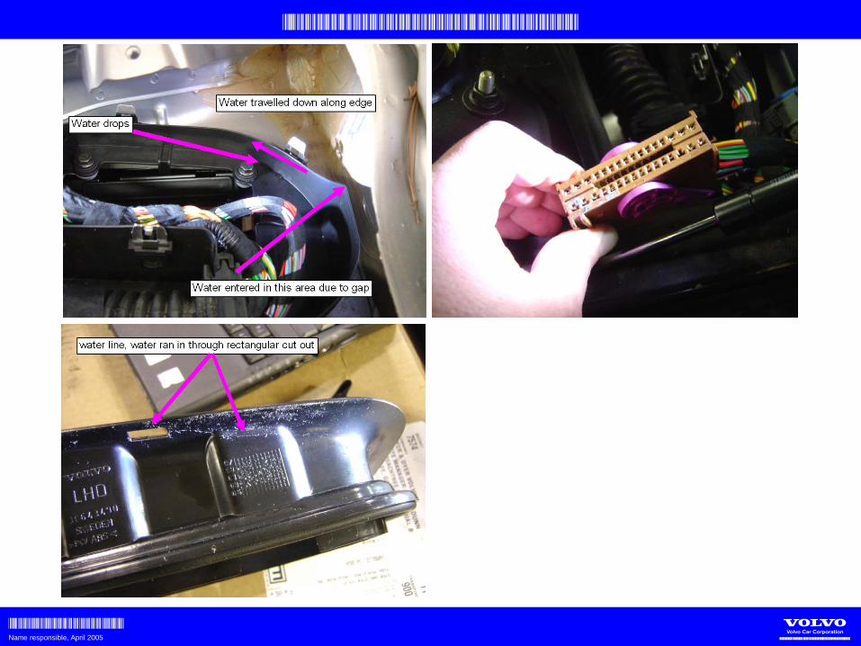
P2PROBLEM DESCRIPTION:
Under specific weather conditions (alternating above/below freezing) there is a riskfor the plenum drains to freeze. As a result, water builds up in the plenum box.
CONSEQUENCES:- Water leakage into plenum box – possible CEM damage.
=> Through rubber grommet (butyl introduced MY05)=> Through top lid=> Through “Octopus”=> Other
- Water leakage into car interior via air box.=> Simply goes over the edge of the collar
PRODUCT MODIFICATIONS:- New grommet with improved sealing on the vertical sides - PN 30739162.
BREAKPOINTS:
S60 465194 - .S80 407065 - .V70 Gent 499870 - . V70 Torslanda 499870 - .XC70 192783 - .XC90 189110 - .
P1/P2 Plenum water leakage

VCNA TECHNICAL CONFERENCE APRIL 2005
VCNA CUSTOMER SERVICEName responsible, April 2005 Volvo Carsof North America, LLC.

VCNA TECHNICAL CONFERENCE APRIL 2005
VCNA CUSTOMER SERVICEName responsible, April 2005 Volvo Carsof North America, LLC.
VCNA TECHNICAL CONFERENCE APRIL 2005
VCNA CUSTOMER SERVICEName responsible, April 2005 Volvo Carsof North America, LLC.

VCNA TECHNICAL CONFERENCE APRIL 2005
VCNA CUSTOMER SERVICEName responsible, April 2005 Volvo Carsof North America, LLC.
P1/P2 Plenum water leakageP2SERVICE (TJ 8529):
- Locate area of leakage and correct - Seal grommet with sealant PN 1161235. - Seal plenum box top lid with sealant PN 1161235.- Replace CEM/engine bay harness if there is corrosion.
TECHNICAL REPORT:
- Yes! Submit a TR with root cause for the water penetration.
* Was the top lid of the plenum box correctly fitted?* All 5 clips in locked position?* Guide pins on top lid correctly seated inside the plenum box?* No wires caught in between top lid and box?* Top lid sealing undamaged?* Seal between plenum box and body undamaged?* Plenum drainage open on both sides?* Car interior wet? Other?

TC Charlotte w811, VCNA Technical Support B&T, Andy McCloskey - Martin Hansson, VCC Peter Ahlberg
Page 1Issue date: 2008-2-25, Security Class: Proprietary
BODY AND INTERIORMarch 2008
Peter Ahlberg, Andy McCloskey, Martin HanssonCharlotte NC, USA

TC Charlotte w811, VCNA Technical Support B&T, Andy McCloskey - Martin Hansson, VCC Peter Ahlberg
Page 2Issue date: 2008-2-25, Security Class: Proprietary
XC90, Water leakage from sunroof drainage system.DESCRIPTION:Reported via TR:s that we still have issues with water leakege from the sun roof. Hose clogged
Sound trap cloggedHose pinched
HELP needed:We need your help with more TR:s describing the issue.We also need your help with input on the consequences. Parts exchanged, dried out etc.How is it entered in QW90? How to search?

Copyright © 2008 Volvo Cars of North America, LLC. All rights reserved. Page 1 of 5
NO: 37-35 DATE: 02-06-2008 MODEL: All P2X (S60 S80 V70 XC70 XC90) M. YEAR: 2005-2006 (structure week 200425-200540) CHASSIS: XC90 FC1 134000-256551 V70 FC1 459000-555060 S60 FC2 425000-522407 S80 FC1 390000-435423 XC70 FC1 173000-220845 V70 FC2 459000-554206 (FC = Factory code) 11th position of the VIN number SUBJECT: CEM harness terminal corrosion due to water entrance in plenum
(Instruction for new harness installation) REFERENCE: VIDA repair instruction
This document supersedes the previous document dated 5/23/2006. Changes to thisdocument are: Method 2 for later chassis numbers has been deleted since the harness with the integrated grommet and plenum lid is no longer available. Method 1 shall be used for all chassis numbers in the header. Please update your records.
DESCRIPTION: Various electrical function and communication symptoms may occur in MY 2005-2006 vehicles caused by wet corrosion in the CEM connector. The grommet that seals the harness entrance to the Plenum box may not seal properly if it has been incorrectly assembled. This may cause a number of different functionality symptoms and DTC's to be set. Examples include but are not limited to: - Headlights on, even if ignition key is taken out of ignition lock. - Warning messages in DIM (Driver Information Module) display. - Warning lamps lit up. - Brake lights always on. - No start condition.
Tech-Net Notes “Fixed Right – First Time”
Volvo Technicians, Service and Parts Managers

Copyright © 2008 Volvo Cars of North America, LLC. All rights reserved. Page 2 of 5
PRODUCT MODIFICATION: A new plenum sealing strategy with integrated rubber grommet was introduced in production from 2005 week 40. See photo below. This new sealing strategy will be carried over to the replacement engine bay harnesses on the chassis numbers indicated, by modification of the replacement harness.
SERVICE: If there are signs of water penetration in plenum box and/or wet corrosion at the CEM
(central electronics module) connectors, it will be necessary to install a new CEM and replace the engine bay cable harness according to the method below:
Modification of the original type replacement harness
Parts required; • Engine bay cable harness, check VIDA parts catalogue (This is the original type engine bay harness which will be modified with the instruction below) • Plenum lid, P/N 30728860 • Service grommet, P/N 30775689 • Cable tie, P/N P/N 983750 (2 required)
Modified replacement harness

Copyright © 2008 Volvo Cars of North America, LLC. All rights reserved. Page 3 of 5
1.
Removing the existing rubber grommet
Remove the old rubber grommet using a knife.
Caution! Make sure that no hoses or cables are damaged.
IMG-243942
2.
Remove and discard the holder from the new cable harness.
IMG-244520
3.
Remove and discard the existing surround.
Save the attachment screws to attach the new cover to the plenum floor.
IMG-243946

Copyright © 2008 Volvo Cars of North America, LLC. All rights reserved. Page 4 of 5
4.
Installing the new seal
Route the cable harness through the new rubber grommet and cover.
Caution! Exercise caution so that the rubber grommet is not damaged when the connectors are threaded through.
IMG-244521
5.
Installing the new seal, continued
Align the arrows (1) towards each other. Arrow (2) must point towards the handle on the rubber grommet.
IMG-243944
6.
Installing the cable ties
IMG-243945

Copyright © 2008 Volvo Cars of North America, LLC. All rights reserved. Page 5 of 5
7.
Installing the cover
Note: After installation, the cable harness under the cover will be slightly over length. Clamp it up in a suitable manner to prevent chaffing.
Tighten the screws to 10 Nm.
IMG-243947
WARRANTY CLAIM INFORMATION LABOR OP LABOR DESCRIPTION LABOR TIME37349-2 Harness engine comp/dashboard repair See Note below
Claims may be submitted under the new car warranty when there is a documented customer complaint using claim type: 01
Note: General Labor time based on technician time required for repair. This repair is subjected to all audit requirements outlined in the Warranty Policy and Procedure manual.
VOLVO for life, Volvo Cars of North America, LLC Technical Service
Please circulate, read and initial: _____Svc Mgr _____ Parts Mgr _____Shop Foreman
_____ _____ _____ _____ _____ _____ _____ _____ _____ _____ _____ _____ TECHS
_____ Warranty Administrator _____ _____ _____ _____ _____ _____ _____ S. Advisors