Embed Size (px)
Citation preview

TA 2 1Copyright © 2004 NSF Engineering Research Center for Reconfigurable Manufacturing SystemsCollege of Engineering, University of Michigan. All rights reserved
Active Projects1. Reducing unscheduled downtime
(GEMA)2. Performance metrics for wireless
networks (Ford, USCAR)3. Factory-wide time synchronization
(NIST)4. Hardware in-the-loop simulation
(GM) 5. Consolidation of control (RFT)6. Fault Diagnosis Through Automatic
Model Generation for Large-Scale Manufacturing Systems (RFT)
Dawn Tilbury and James MoyneEngineering Research Center for Reconfigurable
Manufacturing Systems ERC/RMSUniversity of Michigan
January 2009
Thrust Area 2: ManufacturingInformation and Control

NSF Engineering Research Center for Reconfigurable Manufacturing Systems
University of Michigan College of Engineering
TA2: Information & Control
TA2: Reducing Unscheduled Downtime Through January 2009 Automated Event-based Control Goal and Deliverables Develop and demonstrate an open-architecture event-driven software control system that (1) links equipment data collection, equipment control and equipment & tool maintenance capabilities and (2) provides for reduction in unscheduled downtime and reduction of Mean-Time-To-Repair (MTTR)
Benefit to Industry • Reduction of unscheduled downtime • Reduction of MTTR • Improved understanding and practice of data collection • Improved maintenance/tool change scheduling • Improved data visibility • Definition of data consolidation approach • Scalable solution that can be applied to other control scenarios
Overview We leverage GEMA1’s data collection infrastructure to acquire OPC data, maintenance data and tool change data; and analyze the relationship between OPC data and maintenance/tool change data. Utilizing the analysis result, we are able to optimize maintenance scheduling/tool change scheduling. Our control solution is an open-architecture, event driven system and thus allows scalability to accommodate other control workflow scenarios.
fin
Figure 1. Overview Of The Control Solution
1 GEMA: Global Engine Manufacturing Alliance
Production
PLCs
OPC
Production Production
PLCs
Production
••
Diagnostics Equipment/ Tool Control
ECA Control System
Maintenance Management
AutomaticShutdown BENEFITS
• Reduced Unscheduled Downtime
• Reduced Scrap
• Reduced MTTR
• Improved Productivity
Optimize Maintenance Scheduling
TODAY
Data Stores Excel
Particular Faults with Top Fault Durations
0
200
400
600
800
1000
1200
1400
OP230B Faulted Event OP230A Faulted Event OP255B NO PARTTYPE AT UNLOAD STATION 2
Fault Description
Dev
iatio
n by
Tot
al D
urat
ion
0
20
40
60
80
100
120
Cum
ulat
ive
Perc
enta
ge
Engineers
Machine Adjustment

Current Status
• Historical data study indicating potential improvement • Report on potential ROI improvement and success metrics • Best Practices document for Maintenance Management generated, which was implemented at
GEMA • Developed automated mechanism for finding trends in process data • Developed mechanism to reporting data to and getting feedback from process engineers • Developed analysis scripts to find anomalies on the plant floor • Developed a user interface for reporting • Study on OPC data collection for data quality analysis • Study on relationship of OPC data and maintenance/tool change data • Demonstration of conservative practice of preventive maintenance • Normalization of overlay correlation plots and method for improving signal to noise ratio in
correlations • A Pareto user interface for viewing top 10 faults on plant floor • Linked the Pareto user interface with the Java script of finding top 10 faults • Provided a user manual on system requirements, installation instructions and user instructions for
the Pareto user interface and the associated Java script • A MATLAB user interface for viewing plots of faults vs. maintenance • Study on the fault type classification which may improve the result of top 10 faults and relationship
between faults and maintenance • Installed evaluation versions of Excel and MATLAB interface at GEMA and in the process of
testing the software for improvements • Study of relationship between process OPC data and process rejects (quality) data • Created UML plan for future of data quality
Future Milestones Next Quarter:
• Evaluate and improve the software systems installed at GEMA • Work with GEMA to implement data layer above various data systems at GEMA • Study correlation of process and quality data to identify quality affecting process parameters
Next Year:
• Methodology for determining optimum maintenance and tool change scheduling • Improved scheduling of maintenance and tool change • Investigation of methods for increasing productivity of test stand analysis using statistical methods. • Improve data quality and develop specifications for improvements in data collection systems

NSF Engineering Research Center for Reconfigurable Manufacturing Systems
University of Michigan College of Engineering
TA2: Information & Control
TA2: Wireless Networks for Industrial Automation January 2009
Problem:
Desire to move to wireless for aspects of factory floor networking is hindered by uncertainty in areas of network performance in face of interference, security, determination of implementation areas with highest ROI, and best practices for migrating to and maintaining wireless systems.
Background:
Wireless technology has boomed in the IT sector over the past years. Wireless channels for the delivery of digital information and for data transfer are both economical and efficient. For example any notebook computer these days comes with built-in wireless connectivity possibilities.
These benefits translate well for industrial control networks as well.
Industrial networks for automation are continually evolving as their role becomes further entrenched in the manufacturing process. A move to wireless is congruent with the growing need for agile and modular manufacturing. For example consider the reduced cost for network equipment purchase, installation and maintenance and the increased flexibility when changing plant layouts as well as machine configurations.
Industry has been somewhat hesitant in their move to wireless as networks for automation are complex and critical and there are several risks and questions with wireless networking. Many of these concerns were listed above when the “problem” was defined.
Overview of the work at UoM:
Our group at the ERC is focusing on addressing many of these unknowns. The conditions that deleteriously affect wireless networks can often be esoteric and difficult to isolate.
By approaching this problem from multiple angles;
• device testing
• network simulation
• radio propagation analysis
we are able to capture the dynamics involved in this interaction.
The overriding purpose is to give a plant engineer a-priory knowledge of performance limitations and tools to identify potential liabilities.

Goals:
• Understand how to use wireless in diagnostics, control and safety applications. • Working with USCAR to help the automotive industry migrate cost effectively to wireless on the
factory floor. • Provide a standardized testing mechanism and test plan for making effective wireless reconfiguration
decisions. • Define best practices for wireless operation in factories for Diagnostics, Control and Safety
applications. • Provide a capability for “record / playback” style investigation / recreation in lab / analysis and
reporting, for wireless troubleshooting. • Provide design tools for the planning stage of a wireless setup. • Report on technology trends in wireless systems for control.
Benefit to Industry: • Addresses the unknowns for industries hoping to benefit from wireless automation. • Provides a platform for standardized testing and simulation. • Educates industry partners on tools and practices to meet their performance expectations. • Delivers tools to measure and predict faults.
Preliminary results:
• Testing with industry and in the university show that: • Gain control based mitigation techniques may not be as effective as expected in factory
environments. • With microwave transmissions in closed spaces, multi-path propagation effects dominate system
performance. • There are network algorithm changes that in simulation show appreciable improvement. • Experimental data correlates well with preliminary simulations of network performance.
Current Status:
• Device and technology testing is ongoing. • Radio interference in real shop floors is being captured and analyzed. • Vendor concepts for the next generation of wireless solutions are being evaluated. • Developing Best Practices for wireless implementation is a continuing process along-side testing. • A real time data analysis tool for wireless network performance was designed and made available
online for ERC members.
Future Milestones:
• Release the Wireless Network Simulator (Summer ’09) • Compile the university testing effort into a document for distribution (Summer’ 09) • Release a set of best practices for both deployment and management of wireless networked
control.(Summer ’09) • Release a simulator for Leaky Feeder cable routing and for analysis of antenna placement. (Fall ’09)

NSF Engineering Research Center for Reconfigurable Manufacturing Systems
University of Michigan College of Engineering
TA2: Information & Control
TA2: Manufacturing Network Time Synchronization January 2009 Best Practices Goal and Deliverables The goal of this project is to investigate methods for utilizing timing, time stamping and networked time synchronization protocols such as IEEE 1588 in manufacturing control systems with a case study in semiconductor manufacturing. The deliverables are an assessment of the end to end delay problem to evaluate the benefit of network time synchronization, a semiconductor factory network simulator of an equipment data acquisition system capable of reproducing data traffic in any factory, and recommendations for best methods for utilizing time synchronization mechanisms such as IEEE 1588 as well as time-stamping. Benefit to Industry
• Manufacturing industries moving towards Ethernet for distributed control over the factory network • Factory Equipment Data Acquisition (EDA) systems require precise time synchronization to merge
various data streams • Data quality is critical for precise process control and accurate diagnostics • Lack of time synchronization and accurate time-stamping leads to:
o Events and data being out-of-order o Inaccurate correlation of event occurrence from data o Inaccurate fault diagnostics including false positives
• Synchronization mechanism is needed for factory-wide data collection standards (e.g. OPC, XML)
Overview As shown in Figure 1, the entire manufacturing floor is adopting Ethernet as the sole networking technology. Time synchronization allows us to take advantage of the information consolidation provided by the network to provide improved systems for diagnostics, control and safety. The extent and precision of time synchronization required at various levels of the factory floor needs to be investigated.
Figure 1. Ethernet on the factory floor Figure 2. Factory network simulator architecture

Current Status • Network delay contributions have been quantified and show that device speed and its variability
dominate delays in network communication:
Table 1: Network delay contributions UDP VPN OPC DeviceNet Delay Average (ms) 0.33 1.21 1.48 0.3-1.2 Delay Variation (3σ) (ms) 0.09 0.49 2.43 0.005-0.2 Network Contribution (ms) 0.035 0.035 0.035 0.188 % of Delay Due to Network 11% 3% 2% 63%
• Initial tests with time stamping data packets at the application layer indicate that application
processing time is a dominant cause of variation. • A preliminary version of the simulator shown in Figure 2 has been completed • The simulator successfully creates scenarios typical of equipment data acquisition systems including
the capability for traffic and noise generation and XML messaging seen on the factory floor • The simulator allows for a practical perspective to study the accuracy achievable and potential
network factors contributing to accuracy degradation of factory-wide time synchronization • A study on the time-stamping performance over a wired Ethernet network has been conducted
evaluating various time-stamping methods and locations. • A study on the performance of the time sync. service over wireless media is a current focus area. • A testbed to analyse low level (hardware) time stamping is in the design phase.
Future Milestones 2009:
• Complete study of time synchronization performance over wireless media. • Implement the new scalable design for the EDA simulator. • Develop means to accurately detect the loss of a master clock over the nework and to make
measurements of drift under these conditions. • Design and develop a IEEE 1588 hardware time synchronization testbed • Analyze hardware time synchronization capabilities • Develop best practices for factory-wide time synchronization (allowing for hardware and software
solution components); transfer to standards proposals
References 1. N. Kalappa, J Parrott, Y. Li, and J. Moyne. Practical Aspects Impacting Time Synchronization Data
Quality in Semiconductor Manufacturing. In Proceedings of the IEEE 1588 Conference, October 2006
2. N. Kalappa, J. Baboud, Y. Li, and J. Moyne. Fab-wide Network Time Synchronization – Simulation and Analysis. In Proceedings of the AEC/APC Symposium, September 2007
3. V. Anandarajah, N. Kalappa, R. Sangole, S. Hussaini, Y. Li, J. Baboud, and J. Moyne. Precise Time Synchronization in Semiconductor Manufacturing. Submitted to Proceedings of the IEEE 1588 Conference, October 2007
4. Semiconductor Manufacturing Equipment Data Acquisition Simulation for Timing Performance Analysis”, Ya-Shian Li-Baboud, Xiao Zhu, Dhananjay Anand**, Sulaiman Hussaini, and J. Moyne 2008 International IEEE Symposium on Precision Clock Synchronization for Measurement, Control and Communication (ISPCS) 2008, Ann Arbor, Michigan, September 2008.

NSF Engineering Research Center for Reconfigurable Manufacturing Systems
University of Michigan College of Engineering
TA2: Information & Control
TA2: Virtual Fusion: Integrating Virtual Systems into Jan 2009 Real Manufacturing using Hardware-in-the-Loop
Goal and Deliverables
The goal of this project is to develop a methodology for Hardware-in-the-Loop in which hardware and software components of a manufacturing system can be swapped out for verification, testing, and analyzing logic controllers.
The deliverables are a modular swappable decentralized simulation infrastructure, capable of monitoring a manufacturing process as well as testing various different component scenarios.
Benefit to Industry
• Understand state-of-the-art of simulation in auto manufacturing • Reduce launch time and downtime due to unanticipated behavior • Provide a platform for testing difficult-to-simulate components
Overview
As the world changes, manufacturing processes must become more flexible and more easily implemented. This presents a challenge when simulation and prototyping exist as disjointed pieces of the same process. Using stand alone simulations that may give rise to inaccurate prototypes due to inaccurate models can be a pricely and time consuming exercise. Hardware-in-the-Loop (HIL) can reduce development time and cost. HIL is a process whereby hardware/machinery can be tested in conjunction with a simulation model. This research takes HIL to a new level. The concept of HIL will be applied to multiple different regions on the serial parallel line (Fig. 1). This system will then have many different instances of both real and virtual regions (Fig. 2). We will explore for example what happens when a part travels from a real region to a virtual one and then back again.
Figure 1. Virtual example of Serial Parallel line located in TA2
Figure 2. : Parts can start in a real region traveling through the system transitioning between real and
virtual
Virtual RealReal
part

Current Status
• Understand state-of-the-art of simulation in auto manufacturing • HILS implementation of virtual Fanuc robot on ERC-RFT • HILS implementation of virtual Motoman robot on ERC-RFT • HILS implementation of virtual over head gantry supply cell on ERC-RFT
Future Milestones
Next Quarter: • Monitoring capability • Fidelity metric
Next Year: • 3 dimensional interface • 2 way internet communication • Artificial intelligence controlled system
References
1. Gu, F., Harrison, W., Tilbury, D., and Yuan, C., 2007. “Hardware-in-the-loop for manufacturing automation control: current status and identified needs”. In Proceedings of the Third Anual IEEE Conference on Automation Science and Engineering.
2. Harrison, W., Tilbury, D., 2008. “Virtual fusion: hybrid process simulation and emulation-in-the-
loop”. In Proceedings of the 9th Biennial ASME Conference on Engineering Systems Design and Analysis.

NSF Engineering Research Center for Reconfigurable Manufacturing Systems
University of Michigan College of Engineering
TA2: Information & Control
TA2: Factory Control Logic Consolidation January 2009 Goal and Deliverables The goal of this project is to develop a methodology for control consolidation of manufacturing systems and apply it to the Reconfigurable Factory Testbed (RFT). The RFT currently has a broken Event-Condition-Action (ECA) control hierarchy. This project will improve its reconfigurability, enhance our ability to debug the system, and enable the RFT to achieve factory-wide goals. The deliverables of the project are as follows:
• A methodology to consolidate control hierarchies so that they abide by the ISA-95 standard, while
preserving their ECA nature if originally present • New control hierarchy for the RFT that abides by ISA-95 standard and is ECA-based at the factory
level • Tested, working code to implement the new RFT control hierarchy
Benefit to Industry
• Application of the control consolidation methodology would improve debugging and ability to
achieve factory-wide goals for general manufacturing systems, and improve reconfigurability for reconfigurable manufacturing systems.
• The RFT case study can be used for reference and insight when the methodology is applied to other systems.
Overview Typical factory systems are characterized by fragmented data and control components that often operate as “silos” of control with often times conflicting objectives that do not tie well to overall factory objectives. This fragmentation of control systems, which usually results from the piecewise development and implementation of these systems by different teams, leads to control systems that are non-optimal, difficult to maintain, and very difficult to reconfigure. The Reconfigurable Factory Testbed (RFT) in the ERC-RFT is an example of such a system as it has been developed piecewise by different groups of students, often as part of industry and research projects. The RFT control hierarchy has three levels of control – Factory, Cell, and Machine – with most controllers lying within one level and separated by well-defined interfaces. However, the system level controller (SLC) performs both Factory and Cell level control, as shown in Figure 1, resulting in a broken control hierarchy, causing problems with debugging, and degrading the system’s reconfigurability. To address these problems a methodology is being developed to aid in the control consolidation of manufacturing systems, especially Event-Condition-Action (ECA) based systems. An RFT control consolidation project is being undertaken to guide the methodology development as well as to provide a case study of its use. The ECA paradigm, originally used in active database systems, consists of the arrival of an event (E), the evaluation of conditions (C) associated with that event, and based on this evaluation, the performance of a pre-determined action (A). The CWM and SLC are both ECA-based, where the CWM is a rule engine for a set of ECA rules and the SLC is a set of communicating ECA MFSMs (Modular Finite State Machines) [3]. This shared ECA paradigm simplifies implementation of the consolidation methodology. The methodology can be summarized in the following steps:
• Define the desired control hierarchy • Identify controllers that break the desired control level hierarchy. • Eliminate those controllers by moving their logic to other parts of the system.

o Identify each of its functions with a method, including inputs and outputs o For each method, assess whether its logic should be shifted up or down based on whether
the function it performs is higher or lower level and with which side of the interface (above or below) its inputs/outputs are consistent.
• Re-route any communication that previously went through the eliminated controllers.
Figure 1. RFT Control Hierarchy Prior to Consolidation Current Status
• Basic methodology developed and decisions made about where to move SLC parts and trackers • New code written to replace Cell 1 and Supply Cell parts of SLC, and code tested with RFT • Completed shifting/consolidation of trackers associated with SLC into the next state mapper • Implemented and tested next state mapper on RFT • Investigated options and developed plan for making Cell 2 a replica of Cell 1 except with
PROFIBUS instead of DeviceNet Future Milestones Next Quarter:
• Complete Cell 2 consolidation and testing • Create simple assembly cell controller, separate conveyor controller from old SLC • Develop high-level CWM logic • Test completed consolidated RFT • Write documentation on consolidated RFT
Relevant Publications 1. N. Arora, S. Gala, B. Lee, J. Luntz, J. Moyne, D. Tilbury, “A ‘Controls Workflow Management’ HMI to Configure
and Maintain an Event Based Control System” WODES 06, Ann Arbor, Michigan, July 2005.
2. H. Wijaya, K. Sukerkar, S. Gala, N. Arora, J. Moyne, D. Tilbury, J. Luntz, “Reconfigurable Factory-wide Resource-based System Integration for Control”, IEEE Region 4 Electro-Information Technology Conference, Lansing, May 2006.
3. E. E. Almeida, J. E. Luntz, and D. M. Tilbury, “Event Condition Action Systems for Reconfigurable Logic Control,” IEEE Transactions on Automation Science and Engineering, 4: 167-181, 2007.
4. L. Allen, J. Zhang, J. Moyne, and D. M. Tilbury, “Factory Level Control Consolidation for Event-Condition-Action: Case Study on the Reconfigurable Factory Testbed,” Proceedings of the American Control Conference, 2008.

NSF Engineering Research Center for Reconfigurable Manufacturing Systems
University of Michigan College of Engineering
TA2: Information & Control
TA2: Fault Diagnosis Through Automatic Model January 2009 Generation for Large-Scale Manufacturing Systems Goal and Deliverables The goal of this project is to create a fault diagnosis approach for large-scale manufacturing systems that uses system identification to create an estimated model and fault detection based on that estimated model and information about the model’s uncertainty.
The deliverables are prototype software modules – recording, system identification, monitoring, and fault diagnosis – and the accompanying algorithms and methodology that constitute the fault diagnosis approach; application of the methodology and software to the RFT; and possibly an industrial plant pilot study.
Benefit to Industry
• Event-based fault diagnosis technique for manufacturing systems that are lacking a pre-existing formal model or whose formal model may be incorrect or incomplete or whose formal model cannot be used dynamically for fault diagnosis.
• Algorithms to compare system identification techniques so that the best technique for a particular scenario can be discovered.
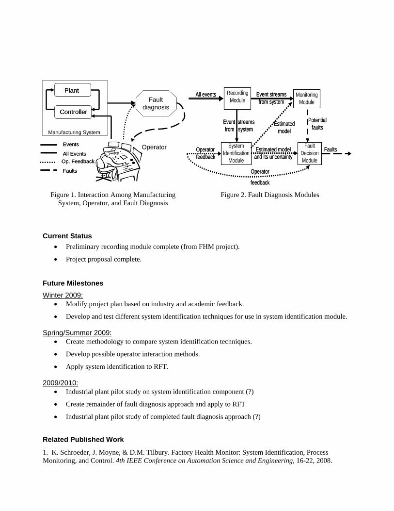
Overview This project addresses the need for fault diagnosis of manufacturing systems that are lacking a pre-existing formal model or whose model is not complete or correct or whose formal model cannot be used dynamically for fault diagnosis. The proposed fault diagnosis solution consists of two major parts: system identification to create an estimated model, and fault decision-making using that estimated model and information about its uncertainty to decide whether a fault has occurred (detection), and using feedback from the operator to learn to classify faults (diagnosis). The Factory Health Monitor (FHM) [1], a previous project with somewhat similar long-term goals, is leveraged to provide a preliminary Recording module, which is necessary for both system identification and fault diagnosis.
System identification can be defined as the ability to characterize a system by its operation. Although ideally, a complete and correct model of the entire system is created at its conception and updated as changes are made, this often is not the case. The ability to model the observed behavior of a manufacturing system provides aids engineers in validating, optimizing, and diagnosing new and existing control logic. An additional benefit specific to the proposed system identification is that it does not interfere with normal operations of the manufacturing system, but rather learns the model through passive observation and possible operator feedback on the quality of the observed system execution.
The proposed fault decision-making technique will use the estimated model produced through system identification and information about the uncertainty of said model to flag or detect faults. During initial stages the system operator will be notified that a fault has been detected and given diagnostic information about where the deviation occurs between the model and the execution so the operator can diagnose the exact fault. In future work, the system operator will provide feedback to the fault decision module, indicating which fault was associated with which deviation, so that the fault decision module can learn to diagnose faults on its own.
PlantPlant
Manufacturing System
Faultdiagnosis
Faultdiagnosis
All Events
Events
Op. Feedback
Faults
All Events
Events
Op. Feedback
Faults
Operator
ControllerController
Monitoring Module
Monitoring Module
Recording Module
Recording Module
Fault Decision Module
Fault Decision Module
FaultsFaultsSystem Identification
Module
System Identification
Module
Operator feedbackOperator feedback
Estimated model and its uncertaintyEstimated model
and its uncertainty
Estimated model
Estimated model
Potential faults
Potential faults
All eventsAll events Event streams from system
Event streams from system
Event streams from system
Event streams from system
Operator
feedback
Operator
feedback
Figure 1. Interaction Among Manufacturing System, Operator, and Fault Diagnosis
Figure 2. Fault Diagnosis Modules
Current Status
• Preliminary recording module complete (from FHM project).
• Project proposal complete.
Future Milestones Winter 2009:
• Modify project plan based on industry and academic feedback.
• Develop and test different system identification techniques for use in system identification module. Spring/Summer 2009:
• Create methodology to compare system identification techniques.
• Develop possible operator interaction methods.
• Apply system identification to RFT. 2009/2010:
• Industrial plant pilot study on system identification component (?)
• Create remainder of fault diagnosis approach and apply to RFT
• Industrial plant pilot study of completed fault diagnosis approach (?)
Related Published Work
1. K. Schroeder, J. Moyne, & D.M. Tilbury. Factory Health Monitor: System Identification, Process Monitoring, and Control. 4th IEEE Conference on Automation Science and Engineering, 16-22, 2008.


TA 2 2Copyright © 2004 NSF Engineering Research Center for Reconfigurable Manufacturing SystemsCollege of Engineering, University of Michigan. All rights reserved
Completed and Archived Projects1. Development, application and
transfer of a network ROI cost calculator (Pilz, Chrysler)
2. Industrial Ethernet testing (GM)3. Automatic logic generation
(Ford)4. Control logic verification5. Improving quality while reducing
cost through virtual inspection and process control
6. Enterprise-wide control7. Implementation of
reconfigurable logic control (NI)Dawn Tilbury and James Moyne
Engineering Research Center for Reconfigurable Manufacturing Systems ERC/RMS
University of MichiganJanuary 2009
Thrust Area 2: ManufacturingInformation and Control

NSF Engineering Research Center for Reconfigurable Manufacturing Systems
Professor Dawn Tilbury ([email protected]) Dr. James Moyne ([email protected])
Development, Application, and Transfer of a Network ROI Cost Calculator
Kyle Schroeder September 2007
Introduction With a variety of different network configurations and protocols a fundamental question that must be explored is “how much does a network actually cost?”, and “what is the relative cost of reconfiguring a network?” Any complete solution to this question must analyze the initial and recurring costs of a network and be flexible enough to be updated as technology changes. Resolving this issue is fundamental to plant floor network architectures and delivery of high Return-On-Investment. Results of applying a weighted cost calculator to the network design and reconfiguration process will aid in the development of a more cost effective network from the initial design through all stages of reconfiguration including adding or updating nodes, and adding in functionality such as safety. Background
Engineering and Maintenance Cost
Hardware and Installation Performance
Cost Network Delays
# of Networks, # of Nodes
And Cost of Nodes
System Complexity The purpose of a network is to reduce cost and
improve performance and capabilities of the networked system. As networks proliferate throughout the factory, the associated up-front and on-going costs are significant. Traditionally, networks have been divided along the general lines of functionality: control, diagnostic, and safety. However, these lines are blurring and the ability to calculate the ROI of a network is becoming more complex. Cost Calculator In a very general sense, each network configuration has advantages and disadvantages. For example a network configuration dedicated to a particular function such as control will be easier to set up, configure, and maintain than a network that shares multiple functions (such as control and safety) due to the interactions of two sets of performance requirements. System complexity impacts the performance, engineering, and maintenance costs of a system and hence is a significant issue. A benefit of shared networks is that they often have lower hardware (fixed) costs, while individual networks in some instances can have lower performance (recurring) costs. In order to generalize this cost a two-tiered cost calculator was developed to include relevant costs that should be included when network cost is to be calculated. Each of the top tier terms can be further broken down to include second tier costs. In such an

incremental cost calculator, terms can be added as the body of research on actual cost grows.
PPEH
PE
PEH
E CostWWW
WCostWWW
W)()( ��
���H
PEH
Htotal Cost
WWWWWCost
)(�
���
Cost Calculator Application An application was developed to aid in the research to further characterize the network costs and weights. The calculator has an easy to use Excel interface with a VBA code backbone. The output from the calculations is presented in Excel and therefore is easy to use and display. This type of functional macro allows for modularization and for the addition of proprietary performance and engineering cost calculators, such as the PILZ SafetyBUS p calculator. Currently the network cost calculator application is being used to characterize the total network cost of the RFT. The output from this scenario has been beneficial in providing insight into what has driven the cost of the RFT network. The calculator is available for application in the analysis of networking data . In other words the application of this process will provide networking ROI information, and also provide input into the improvement of the calculator. A second version of the software has been developed that further facilitates usability and customization of the software. Future Work With the calculator baseline in place the major work that remains in this project is to develop the terms in the cost calculator. While the hardware and engineering costs of a network have been defined in terms of monetary measurements that can be easily defined and measured, the methods required to find the cost of poor network performance are not straightforward and will require a significant effort to define. To move forward, tests will be needed to gather network performance data that can be used to develop the terms and weights of the cost calculator. Acknowledgements This research was sponsored in part by PILZ Automation USA and the Engineering Research Center for Reconfigurable Manufacturing Systems of the National Science Foundation under Award Number EEC-9529125. References [1] IEC 61508, Functional safety of electrical/electronic/programmable electronic safety-related systems, 2001. [2] Moyne, James, Bradley Triden, Aditya Thomas, Kyle Shroeder, and Dawn Tilbury. "Cost function and tradeoff
analysis of dedicated vs. shared networks for safety and control systems." Automated Technology in Practice 2(2006): 22-31.

NSF Engineering Research Center for Reconfigurable Manufacturing Systems Prof. Dawn Tilbury ([email protected]) Dr. James Moyne ([email protected])
University of Michigan
Industrial Ethernet Testing Project Naveen Kalappa, Marco Antolovic, Kristen Acton,
Jonathan Parrott, Siddharth Mantri October 10, 2006
Objective
Evaluate the network performance of EtherNet/IP and PROFINET, two widely used Industrial Ethernet specifications.
Background
Ethernet is being increasingly used as an industrial automation network. This is because of the low cost, interoperability, higher data rates and the rapid technological developments taking place due to its wide usage. EtherNet/IP and PROFINET are two such widely used industrial Ethernet solutions.
The two specifications represent different implementations of the Ethernet protocol stack. Identical tests were conducted on both, and their network performance in terms of the delay and jitter characteristics was analyzed. The tests focused on peer-to-peer (between two communicating PLCs), network management and HMI. In addition, an in-depth technology comparison of both specifications was conducted to identify the features offered.
Test Set Up
Figure1: Test configuration with multiple PLCs exchanging data over a switched network

Tests and Evaluation Conducted
Though the tests conducted were generic, emphasis was placed on the requirements of General Motors Powertrain.
� Peer-to-peer performance tests: Parameters such as network architecture, network traffic, data size, number of data items, number of connections and processor load were varied and their effect on network performance was noted. Ethereal was used as the tool to capture data from the network
� Network management and HMI tests: Through network management tests, the impact of changing network features and their effect on communication between the PLCs was analyzed. Also the response to PLCs supporting either protocol to standard network management tools (IntraVUE utilizing SNMP) was determined. In the HMI tests, parameters such as the number of tags, tag update rate and architectures were varied between HMI and communicating PLCs and their effects studied.
� Technology Analysis Report: A comprehensive technical report detailing the features supported from both specifications in areas such as their implementation, ease-of-use, communication (peer-to-peer, I/O), safety, security has also been compiled
Results
Figure 2: PLC Packet Interval Figure 3: Round Trip Time Interval
Shown above are example test results for the peer-to-peer performance tests with two communicating PLCs. Packets were generated from one of the PLCs, and the second PLC echoed the packets generated by the first. In Figure 2, the max, min, avg and standard deviation of generated packets by a PLC for an update interval of 8ms is indicated. Figure 3 shows the round trip time interval for an update interval of 8ms. Round trip time is time taken for completion of a loop i.e. from first PLC to the second and back to the first.Detailed reports are available at: http://erc.engin.umich.edu/publications/pub-TA2.htm
Conclusions
Based on the results of the tests conducted, both protocols, PROFINET and EtherNet/IP are expected to meet the needs of peer-to-peer communication in a manufacturing plant.
Acknowledgements
ERC would like to thank General Motors Powertrain, Rockwell Automation, Siemens and Hirschmann for their support in the execution of this project.

NSF Engineering Research Center for Reconfigurable Manufacturing Systems Prof. Dawn Tilbury ([email protected])
University of Michigan Les Lee ([email protected])
Ford Motor Company
Automatic Logic Code Generation: Evaluation, Assessment, Recommendations
Seungjoo Lee/Dawn Tilbury
Summary of the Initiative: To ensure consistency of logic control codes across multiple machine vendors, and to enable improved diagnostics and reconfigurability, Ford Motor Company is investigating the use of automatic logic code generation tools. The University of Michigan ERC/RMS has developed several methodologies for automatic logic generation (including for transfer lines and flexible manufacturing cells) and has experience in applying Tecnomatix eM-PLC logic generation tools. The purpose of this project is to (1) evaluate the state-of-the-art in commercially-available automatic logic generation tools through implementation on a test rig at Ford, (2) survey the state-of-the-art of academically-proposed methods, and (3) recommend a set of required capabilities that are needed to realize the vision of automatic logic code generation for all machines purchased by Ford Powertrain Operations. Statement of Work: Ford has purchased a test rig for the evaluation. Ford engineers will be trained in Enterprise Controls by Rockwell. ERC/RMS researchers have already been trained in eM-PLC by Tecnomatix/Siemens. The two approaches for automatic logic code generation will be applied to the test rig, and the researchers and engineers will compare the two approaches for usability, functionality, etc. The survey of academic approaches will be done by the ERC/RMS. Recommendations, taking into account the best features of the commercially-available tools and the best ideas of the academic methods, will be agreed upon jointly by the ERC/RMS and Ford. Deliverables: � Logic control code for test rig automatically generated by multiple commercially-available tools � Survey report of academic methods proposed for automatic logic code generation � Report summarizing the capabilities of the available automatic logic code generation methods:
Process definition, programming/editing methods, inclusion of diagnostics, reconfigurability � Recommendations for “best practices” in automatic logic code generation Benefits to Ford: � Critical assessment of existing and proposed automatic logic code generation methods � Reduced time (and cost) for launch, ramp-up, and reconfiguration of complex machining systems Expectations of UM: � Implementation of eM-PLC automatic logic generation on Ford test rig
o Build 3D model, program sequences, generate and validate code � Survey report of methods proposed for automatic logic generation by academic researchers � Collaborate with Ford engineers to write recommendations report

Support required from Ford: � Access to test rig � Identification and acquisition of commercial tools for testing � Engineering time for implementation of Enterprise Controls on test rig � Collaborate with ERC/RMS researchers to write recommendations report Results: � Built 3D model of test rig in eM-Engineer � Wrote process definition in eM-PLC, generated logic code, and tested with virtual factory � Built logic model of test rig in RSTeststand � Generated logic code with Enterprise Control, and tested with RSTeststand � Time required to develop and debug code with two methods � Measurements of control size, modularity and data accessibility using metrics from [1] � Final report [2] References: [1] M. R. Lucas and D. M. Tilbury, “Methods of Measuring the Size and Complexity of PLC Programs in Different
Logic Control Design Methodologies,” International Journal of Advanced Manufacturing Technology, 26(5–6):436–447, September 2005.
[2] Mark Ang, Jason Lee, Les Lee, Seungjoo Lee, and Dawn Tilbury, “Automatic Generation of Logic Control,” ERC Technical Report, July 2006.
Test rig modeled in eM-Engineer Control specifications prepared in eM-PLC
Sequential function charts generated by eM-PLC for Siemens Step 7 Verification of control with virtual models
NSF Engineering Research Center for Reconfigurable Manufacturing Systems Prof. Dawn Tilbury ([email protected]) Dr. James Moyne ([email protected])
University of Michigan
Control Logic Reconfiguration & Verification
E. E. Almeida/D. M. Tilbury
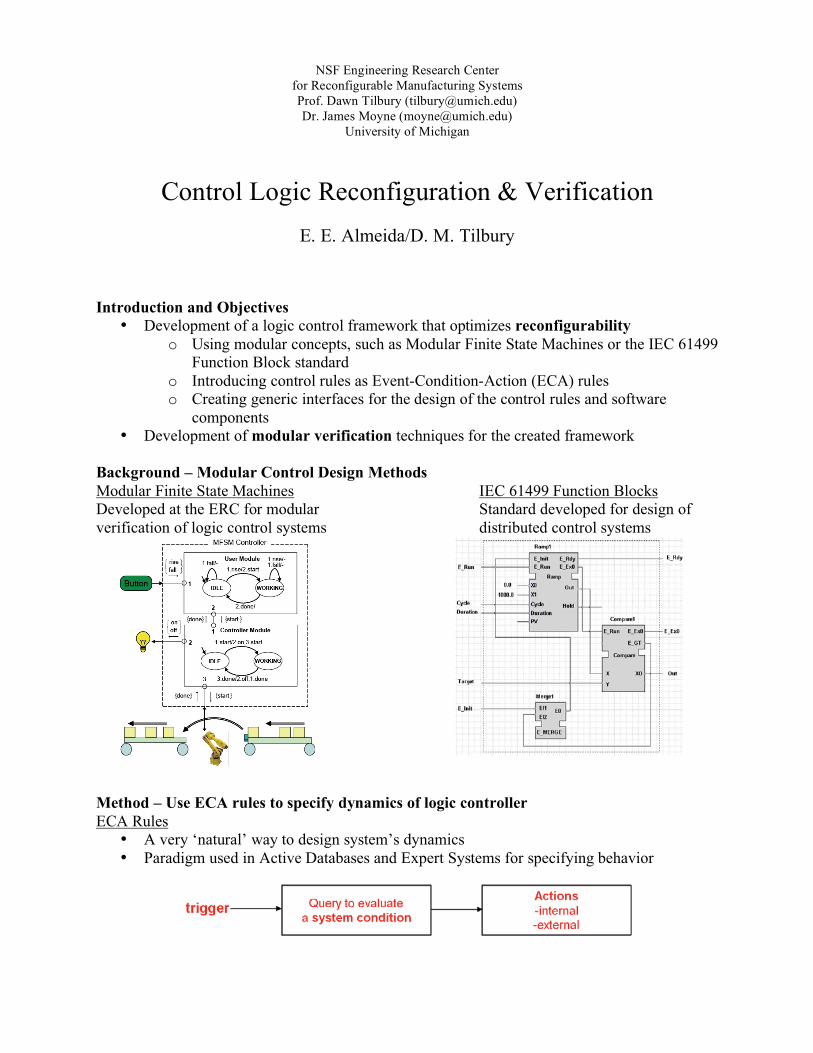
Introduction and Objectives
• Development of a logic control framework that optimizes reconfigurability o Using modular concepts, such as Modular Finite State Machines or the IEC 61499
Function Block standard o Introducing control rules as Event-Condition-Action (ECA) rules o Creating generic interfaces for the design of the control rules and software
components • Development of modular verification techniques for the created framework
Background – Modular Control Design Methods Modular Finite State Machines IEC 61499 Function Blocks Developed at the ERC for modular Standard developed for design of verification of logic control systems distributed control systems
Method – Use ECA rules to specify dynamics of logic controller ECA Rules
• A very ‘natural’ way to design system’s dynamics • Paradigm used in Active Databases and Expert Systems for specifying behavior

Results Creation of ECA Logic Systems
Design of ECA Rules Reconfiguration
• Reconfiguration has been measured from resulting levels of: a. Modularity b. Integrability c. Diagnosability
• The ECA approach shows higher levels of all 3 measures compared to other modular logic control design approaches
Conclusions
• Using ECA rules to design logic controllers o Improves reconfigurability o Facilitates integration with other ECA system components, such as MES, etc… o Provides a generic design approach and an easy way to design control rules
Future Work
• Development of smart modular verification methods for ECA logic systems o Rules are responsible for the dynamics - their correctness must be verified! o Exploit special structure and relevant concepts such as rule confluence
• Development of a generic interface to design ECA rules and Peripheral Modules • Consolidation of logic control with higher level system control
Relevant Publications: E. W. Endsley, E. E. Almeida, and D. M. Tilbury, “Modular Finite State Machines: Development and Application to Reconfigurable Manufacturing Cell Controller Generation,” Control Engineering Practice, 14(10):1127–1142, October 2006. E. E. Almeida, J. E. Luntz, and D. M. Tilbury, “Event Condition Action Systems for Reconfigurable Logic Control,” accepted for publication in IEEE Transactions on Automation Science and Engineering, May 2006. E. E. Almeida, J. E. Luntz, and D. M. Tilbury, “Reconfigurable Logic Control Using IEC 61499 Function Blocks,” Proceedings of the IEEE Conference on Emerging Technologies and Factory Automation, Prague, September 2006.
Write the manufacturing ECA logic control rules as a table Write the manufacturing ECA logic control rules as a table
2 Implementations: • RFT System Level Controller • RFT Cell 1 Controller

NSF Engineering Research Center for Reconfigurable Manufacturing System College of Engineering, University of M1525 H.H. Dow
ichigan Contact: Prof. Dawn Tilbury ([email protected])
Dr. James Moyne ([email protected])
Bldg Tel: (734)763-9999
Ann Arbor, MI 48109 2350 Hayward St. Fax: (734) 763-5700
Improving Quality While Reducing Cost Through Virtual Inspection/Metrology and Process Control
Aftab Khan ([email protected])
September 28, 2007 Introduction and Background In most manufacturing processes, product quality control on a part-to-part or run-to-run (R2R) basis is highly desirable to compensate for process drifts and external disturbances. In this project we propose a predictive inspection (virtual metrology) based process control solution for a variety of manufacturing processes.
Problem: R2R control requires metrology data after each process run, which in some cases is not readily available (only a sampling of the parts are measured) or is only available at a cost of overall process throughput or cycle time (due to the time required for measurements).
Solution: Process diagnostic data is already collected in real time for purposes of fault detection and classification (FDC). This large amount of diagnostic data can be used to predict the product quality for every process run.
Benefits: The predicted product quality can be used as feedback to a control system that improves the product quality while reducing the need for post-process measurements. It also improves response to process disturbances and shifts. A factory-wide implementation of the approach can improve factory objectives such as improve throughput/yield and reduce cycle time/fabrication cost.
VM based R2R control 1. Virtual metrology Module: Multivariate analysis of FD data is performed to find a meaningful
relationship between FD data and product quality. Partial least squares (PLS) regression technique is modified to build VM module for a multi-input multi-output (MIMO) process. PLS has been proven to provide superior results to Principle Components Analysis (PCA) and standard multivariate regression techniques in this domain.
2. Process controller: Standard model-based adaptive “R2R” controllers (e.g. exponentially weighted moving average (EWMA) controller, model predictive controller (MPC), etc.) are modified to deal with virtual as well as actual metrology data.
3. Update of VM module and process controller: Actual metrology (on sampled products) is used to update the VM and controller parameters (dashed line in Figure 1).
Figure 1: Schematic of VM based R2R process control

VM based R2R control for two consecutive processes: Results
VM modules and R2R controllers are developed for two consecutive MIMO process (simulated), in which the VM module of the second process also uses pre-process metrology (predicted + virtual). For both processes every 10th part is assumed to be measured at the metrology station.
Figure 2 compares the y1 response of the first process when an L2L process controller uses only the actual metrology and when a R2R process controller uses VM. It is clear from the figure that the L2L controlled output drifts away from the Target between metrology events while the R2R controlled output is close to the Target. Figure 2: Advantage of using VM in R2R process control (process-1)
In Error! Reference source not found., the y2 response for process-2 is shown to be superior when the VM module uses pre-process
Figure 3: Using pre-process metrology in process control (process-2) Conclusions Market demands for high product quality and low cost necessitate R2R process control with VM. The results show that the VM based process control compensates for process drifts and disturbance on a R2R basis. Therefore product quality is improved without the need for measuring every product, thus saving the cost and time involved in employing extra metrology stations.
Future Work Design new metrology strategies using VM data: measure products recommended by VM only thereby reduce metrology costs. Integrate VM with factory CMMS: Schedule maintenance events on the machine using information from the VM modules, thus reduce maintenance costs.
Publications 1. Aftab Khan, James Moyne, and Dawn Tilbury, “Utilizing in-situ diagnostics to enable manufacturing process control
through predictive inspection,” in Proc. of AEC/APC Symposium XVII, Indian Wells, California, Sept. 2005. 2. Aftab Khan, Dawn Tilbury, and James Moyne, “Predictive-inspection based process control in end milling operations,”
in Proc. of ASME International Mechanical Engineering Congress and Exposition (IMECE), Orlando, Florida, Nov. 2005
3. Aftab Khan, James Moyne, and Dawn Tilbury, “Predictive-inspection based control using diagnostic data for manufacturing processes,” submitted to ASME Journal of Manufacturing Science & Technology.
4. Aftab Khan, James Moyne, and Dawn Tilbury, “Virtual metrology and feedback control for semiconductor manufacturing processes using recursive partial least squares,” submitted to Journal of Process Control: special issue on advanced process control in semiconductor manufacturing.
5. Aftab Khan, James Moyne, and Dawn Tilbury, “Factory-wide control utilizing virtual metrology,” submitted to IEEE Transactions on Semiconductor Manufacturing: special issue on APC.

Contact: Prof. Dawn Tilbury ([email protected])
Dr. James Moyne ([email protected])
College of Engineering, University of Michigan 1525 H.H. Dow Bldg Tel: (734)763-9999 2350 Hayward St. Fax: (734) 763-5700 Ann Arbor, MI 48109
NSF Engineering Research Center for Reconfigurable Manufacturing System
Enterprise - Wide Control Namrata Arora, Shyam Gala
Introduction
Software systems in the factory have generally been integrated from the ground up (i.e., rarely with thought towards an enterprise-wide architecture in the initial stages). Over the past few years the industry has begun to address the issues of lower software reliability and higher software integration, reconfiguration, and maintenance costs by attempting to define elements of a software infrastructure for manufacturing. Our Enterprise-wide software architecture addresses the above with the following salient attributes:
� Event driven system � Data-centric architecture � Web-Enabled HMIs � Reconfigurability during run-time � Support for both control and diagnostics activities � Distributed Environment � Enterprise-wide consolidated resource-based control environment � Easy to visualize and re-configure visually.
Solution Design
Software control systems have been utilizing the ECA paradigm to realize flexible event- based control systems. In event-based systems, actions are performed in response to events based on current conditions. In our system, this action is a sequence of resource utilizations and the ECA paradigm is realized using a database to house ECA rules.
Figure 1: Event-Condition-Action Paradigm
The Resource-Based Management Solution architecture consists of modular components. One of the common approaches used is Web Services, which allow the infrastructure to be distributed enterprise wide. This allows remote access to Software Resources, where each software engine is a modular unit performing a unit task or a logical block of tasks. Middleware Server will create an individual thread for every event that requests a service. Control Workflow Manager maintains the integrity of control (workflow) rules used to coordinate the hardware and software resources. Web Services Communicationamong components is formalized utilizing industry standard protocols such as Simple

Object Access Protocol (SOAP), Extensible Markup Language (XML), Transmission Control Protocol/Internet Protocol (TCP/IP), and OLE for Process Control (OPC).
Figure 2: Solution Architecture Design Results
� Solution implemented for cell and factory-level control of the Reconfigurable Factory Testbed--RFT (Oracle database, Web-services SOAP/XML module integration)
� Verification of capability and advantage over traditional control approaches utilizing RFT test case.
� Module Integration cradles for Matlab, C++ and Java. � Modules integrated and utilized in ECA rules: Maintenance Management, Part
Ordering, HMI, Diagnostics, Out-of-Control Action Plan (OCAP) � "Control Rules Management" HMI for CWM
Looking Ahead
� Verification capabilities for the CWM � Support for Visualizing Nested Events for more ergonomic electronic white
board.
References 1. H. Wijaya, K. Sukerkar, S. Gala, N. Arora, J. Moyne, D. Tilbury, J. Luntz, “Reconfigurable Factory-wide Resource-
based System Integration for Control”, IEEE Region 4 Electro-Information Technology Conference, Lansing, May 2006
2. K. Sukerkar, H. Wijaya, J. Moyne, D. Tilbury, “An Integrated Distributed Software System for Reconfigurable Manufacturing,” Advanced Manufacturing Technologies 2004, London, Ontario, Canada, June 2004.
3. J. Moyne, D. Tilbury, H. Wijaya, “An Event-Driven Resource-Based Approach to High-Level Reconfigurable Logic Control and Its Application to a Reconfigurable Factory Testbed,” 3rd CIRP Reconfigurable Manufacturing Conference, Ann Arbor, Michigan, May 2005.
4. N. Arora, S. Gala, B. Lee, J. Luntz, J. Moyne, D. Tilbury, “A ‘Controls Workflow Management’ HMI to Configure and Maintain an Event Based Control System” WODES 06, Ann Arbor, Michigan, July 2005

Contact: Prof. Dawn Tilbury ([email protected])
Dr. James Moyne ([email protected])
NSF Engineering Research Center for Reconfigurable Manufacturing Systems College of Engineering, University of Michigan 1525 H.H. Dow Bldg Tel: (734)763-9999 2350 Hayward St. Fax: (734) 763-5700 Ann Arbor, MI 48109
University of Michigan – National Instruments National Instruments Programmable Automation
Controller for Reconfigurable Logic Control: Implementation and Evaluation
Krishnakumar Ramamoorthy
February 22, 2007 Background: National Instruments (NI) has been promoting a new class of industrial controller called Programmable Automation Controller (PAC). The PACs are as rugged and reliable as PLCs and the PACs can be programmed using open programming languages such as LabVIEW, JAVA and C. In this project, the NI PACs are used for implementing the control of medium-size-manufacturing test beds. The implementation is used for evaluating PAC for reconfigurable manufacturing system control. Goal: The purpose of this project is to (1) Develop a suitable execution model for the NI PAC (2) Use LabVIEW for logic control of a high volume transfer line and address issues such as error handling and Human Machine Interface (HMI) (3) Develop logic control for a flexible manufacturing system to address issues such as resource allocation, multiple parts and part re-routing (4) Use commercial-off-the-shelf (COTS) components available in PACs to integrate with larger system such as the Reconfigurable Factory Testbed (RFT) (5) Evaluate NI PAC for reconfigurable logic control. The motivation behind the research is to demonstrate and evaluate the NI PAC for reconfigurable control of manufacturing system. The results of the research could help promote research and development of PACs. Test set up:
� The NI FieldPoint controller as the Programmable Automation Controller � The LabVIEW state diagram toolkit for developing the control logic � The Fischertechnik linear test bed with three work stations as a high volume transfer line � The Fischertechnik rotary test bed with three work stations as a flexible manufacturing system
Fig 1. Linear test bed Fig 2. Human Machine Interface

Method: (1) Used the LabVIEW execution trace tool kit to determine the execution model (2) Developed the logic control of the linear test bed using the state diagram toolkit of LabVIEW
- Translated the existing MFSM code of the linear test bed into the state diagram toolkit [4]. (3) Developed the logic control of the rotary test bed using the state diagram toolkit of LabVIEW
- Adapted the methodologies developed for the flexible manufacturing systems [2] for LabVIEW. (4) Assessed the re-configurability of LabVIEW control logic. (5) Integrated the linear test bed as the wheel processing station of the RFT by using COTS such as
XML and TCP/IP (CWM). Results:
� Scan based execution model of PLC was chosen for its determinism. � Reconfigurable MFSM control code was translated into LabVIEW state diagram toolkit. � Reversible and irreversible modules were used for integrating manual mode error handling. � Methodologies for flexible manufacturing system control code were adapted for LabVIEW finite
state machine. Multiple parts and part-rerouting were implemented. � The LabVIEW control logic proved to be reconfigurable. The seven finite state machines used for
modeling part type 1 were re-used for part type 2. � The control code of one of the work stations of the rotary test bed was re-used for other work
stations. � The linear test bed was integrated into the RFT as the wheel processing station.
I/O operations are less deterministic
I/O operations are more deterministic
Fig 3. Results of execution trace toolkit before and after implementing scan based execution model. Future work
� Model based design of Logic control for PAC. � Auto generation of logic control code for PAC.
Acknowledgement This research was sponsored in part by National Instrument and ERC/RMS References [1] E. Park, D. M. Tilbury, and P. P. Khargonekar, A modeling and analysis methodology for modular logic controller of machining systems using Petri Net formalism. IEEE Transactions on Systems, Man, and Cybernetics: Part C, 31(2):168 � 88, 2001. [2] S. Lee and D. M. Tilbury, A modular control design method for a flexible manufacturing cell including error handling. In Proceedings of IEEE Conference on Decision and Control and European Control Conference, 2005. [3] S. Lee, A cell controller design methodology including error handling for flexible manufacturing system, PhD thesis, Department of Mechanical Engineering, University of Michigan, Jan 2006. [4] E.W. Endsley, Modular Finite State Machines for logic control: Theory, verification and applications to Reconfigurable Manufacturing Systems, PhD Thesis, Department of Mechanical Engineering, University of Michigan, 2004.

By providing a collaborative mix of hardware/software and real/simulation components distributed across a web-enabled network, the RFT serves as excellent environment to consolidate and showcase results of the University of Michigan’s Engineering Research Center for RMS. More importantly, it provides an environment to envision, rapidly prototype, and verify in a factory operation environment those solutions that result from the combination of the RFT components. Further it will provide a mechanism for pre-qualification of factory reconfiguration strategies.
Figure: Reconfigurable Factory Testbed Schematic
RFT Components The envisioned testbed is schematically represented in the figure. The primary components of the testbed are:
Serial-Parallel Line: This line consists of two cells with two table top CNC machines and a robot each, connected in series by a conveyor. This line will be utilized in the study of planning and scheduling as it relates to reconfigurable manufacturing.
Remote Viewing and Collaboration Tools: The RFT employs a remote Human Machine Interface (HMI) to provide connectivity for diagnostics, maintenance, and order placement, utilizing data gathered from sensors/machines using OPC and XML. These web-based tools also give researchers and partners at other universities and commercial sites access to this state-of-the-art facility.
Virtual Factory: A commercial factory simulation software package is used to simulate not only the serial-parallel machining line and the assembly cell, but also additional factory components that do not exist in hardware. The virtual factory is actually linked into the system to enable real + virtual simulations.
Radio Frequency Identification (RFID): It is integrated to RFT for process, product, and people traceability. The system uses high frequency 13.56 MHz with write/read transponders. Safety System: The RFT system employs state-of-the-art safety components, to accomplish a level of standardized safety equal to the most advanced manufacturing facilities. Further research is being conducted on the advantages of such safety systems interacting with control networks to provide for a more optimized network.
Software Infrastructure: The infrastructure has a data centric architecture where it uses OPC and XML for communications. It has plug-n-play capability for module deployment. The current framework supports modules with Java, Matlab, C++, and Visual Basic 6.0 platform.
RFT Applications and Benefits Research • Networks: Multi-tier networking, Quality of Service and
Quality of Performance for controls and diagnostics. • Control rules and event-based control; modular logic control;
factory-wide consolidated control strategy • e-diagnostics and e-manufacturing. • Part program reconfiguration based on actual and/or virtual
inspection • Combining/collaborating research efforts on a single platform • Virtual + Real" real-time simulation and prediction • Logic controllers • Network time synchronization (IEEE 1588)
Education • Web-distributed system allowing for collaboration with other
universities.
• Exposing students to real-world environments.
Technology Transfer • Web-distribute real + virtual environment allows users to
apply “what-if” analysis and test potential transfer solutions prior to adoption.
• Industrially relevant solutions utilizing off-the-shelf technologies wherever possible, standards (official and de-facto), conforming to industry trends, guided by industry partners.
• Solutions for industrial network management to support control, diagnostics and safety information distribution; consolidated HMI methodology
• Graphical method for control strategy reconfiguration
• RFT designed for technology transfer.
The Reconfigurable Factory Testbed (RFT) is a comprehensive platform that enables research, development, education, validation and transfer of Reconfigurable manufacturing system (RMS) concepts. Re
conf
igur
able
Fac
tory
Tes
tbed
(RFT
)
Contact:- James Moyne, RFT Director [email protected]
NSF Engineering Research Center for Reconfigurable Manufacturing Systems College of Engineering, Univ of Michigan 1525 H.H. Dow Bldg Tel: (734) 763-9999 2350 Hayward St. Fax: (734) 763-5700 Ann Arbor, MI 48109 Fax: (734) 615-0312
![[TA2-D] Emerging Thin Film Technology - KCSkcs.cosar.or.kr/2017/download/program/TA2-D.pdf · 좌장: 김형섭(성균관대학교), 윤성민(경희대학교) TA2-D-1 10:10-10:25](https://img.dokumen.tips/doc/110x75/5fdb7c40f50a9a1dc1051f4d/ta2-d-emerging-thin-film-technology-oe-eeeeoee-oeeeeoee.jpg)


![[TA2] PascaSidang Rev2](https://img.dokumen.tips/doc/110x75/55cf8c945503462b138de4ff/ta2-pascasidang-rev2.jpg)


![[TA2] PascaSidang Rev4](https://img.dokumen.tips/doc/110x75/55cf8c945503462b138de548/ta2-pascasidang-rev4.jpg)