Embed Size (px)
Citation preview

FEBRUARY 5TH, IQ42 FLIGHT "3
Side view of the Me 109F. Compared with the 109E it has a smaller diameter airscrew, a larger spinner, a slightly smaller rudder and a cantilever tailplane.
THROUGH BRITISH EYES A Critical Examination of the Original Messerschmitt Me 109E, the Changes Incorporated
in the 109F, and Some Handling and Performance Tests
RE P O R T S of new German fighters notwiths tanding, the Messerschmitt Me 109 is still Germany ' s mainstay in the single-engined fighter class. The original
Me 109E was fully described and illustrated in Flight of October 24th, 1940. Since then modified versions have appeared, to which we have referred, and pictures of which we have published from t ime to t ime. B y the courtesy of L t . Col. Moore-Brabazon., Minister of Aircraft Production, it has now become possible t o publish an even more critical and detailed examination of the original machine, an outline of the main respects in which the newer model, the Me 109F, differs from the original, and to give some results of handling and performance tests.
. We feel sure t h a t m a n y of our *k»*eaders, and more part icularly those
in the aircraft industry and in the Royal Air Force who have had no opportunity to see the Messerschmitt fighter, will welcome this authori tative evaluation of the merits and demerits of t h e design, its handling characteristics as ascertained by British pilots, and th? features which have caused t h e later version to be such, an improvement on the original in many respects.
Handling Characterist ics General.—The Me 109 is a modern
stressed-skin low-wing monoplane, powered by a Daimler-Benz D B 601 1,150 h.p . inverted V-12 liquid-cooled engine. The following notes on handling characteristics apply only to the Me 109E, no flying experience having
This copyright Flight sketch shows the layout of the original Me 109E cockpit. The cramped position of the pilot is
referred to in this article.
yet been obtained on the more recent version of the Me 109F.
The general conclusion on this aircraft is t ha t , a l though

n 6 FLIGHT FEBRUARY 5TH, 1942
T H R O U C H B R I T I S H EYES
it handles well and has excellent response to the controls at low speeds, all the controls become far too heavy at speeds in excess of 300 m.p.h., the ailerons in particular being virtually solid at 400 m.p.h. This restricts manoeuvrability. Turning circle is also poor, being, for example, 885ft. at 1,200ft., due to the high wing-loading Wing-loading on the Me 109 is 32 lb./sq. ft. These disadvantages greatly detract from the fighting qualities, but are to some extent offset by : -—
Good performance at altitude, the machine having an absolute ceiling of 37,500ft.
Excellent rate of climb; this is developed at low air-speed, hence the angle of climbing is very good.
The direct-injection engine does not cut out or splutter under negative " g " as when diving suddenly to seek shelter in cloud.
The stall is very gentle even under " g , " with no tendency to spinning, and ample warning of the approach of the stall is provided by the aileron vibration and buffeting which sets in as the stall is approached. Owing to high wing-loading, however, stall occurs at quite high airspeeds. Outstanding points in relation to handling are detailed
below: — Take-off.—Flaps are lowered 20 deg. for take-off, the run
being remarkably short, the initial rate of climb excellent. Landing.—Landing is somewhat tricky until the correct
technique is acquired, since the aircraft has to be rotated through a large angle on touch down, due to the abnormally high ground attitude. The wheels are positioned well forward of the C.G., and this allows fierce braking immediately On touch down without causing tail-lift, resulting in a short run. The aircraft can be taxied fast.
Flying Controls.—The flying controls have excellent response and " feel " at low speeds, but are far too heavy for manoeuvring at high speeds. The extreme heaviness of the ailerons makes rolling almost impossible at speeds above 400 m.p.h.
Trim.—The only trimming control adjustable during flight is that of the variable incidence tailplane. Ground adjustment is provided for trim of ailerons, rudder and elevator by bending specified parts of their trailing edges.
The handle of the control column has a safety ) T catch over the gun trigger switch.
The absence of a rudder trimmer is severely felt, since there is a large change of directional trim with speed, and at high speeds the continuous application of rudder necessary to fly straight is very tiring.
Flaps.—Lowering the flaps produces a nose heaviness which can be- readily counteracted by adjustment of tailplane incidence, an operation made easy by the juxtaposition of control' hand-wheels of flaps and tailplane for Simultaneous operation.
On the Me 109E the ailerons are interconnected with the flaps and come down 11 deg. with them; this does not detract from the effectiveness of the ailerons, but makes them feel heavier. This interconnection is not present on the Me 109F.
The very simple and effective flap-position indicator is worthy of note. Lines painted on the slotted flaps at 10 deg. intervals lie under the trailing edge of the wing and successively emerge into the pilot's view as the flaps are lowere^ Take-off and landing positions are indicated by'
differently coloured lines. [This arrangement, simple and usefuL in a day fighter,
would be of little help on a night fighter.—ED.]
Cockpit Control A r r a n g e m e n t s General.—The cockpit is too cramped for comfort. It is
too narrow, has insufficient head-room and a tiring seating position. The cramped position seriously restricts the force which the pilot can exert on the control column, particularly in the lateral direction for aileron operation.
Flying Controls.—The control column, with its offset grip, is well positioned, but the absence of fore-and-aft adjustment for the rudder pedals is a bad feature.
Trimming and Flap Controls.—The variable incidence tailplane and the flaps are controlled by two coaxial hand-wheels arranged close together to be operated simultaneously by one hand, whereby change of trim due to flap operation is readily corrected.
Flap operation is entirely mechanical, by screw-and-nut gear, thus avoiding the vulnerability inherent in hydraulic systems.
Engine Controls.—A feature of the engine controls is the extreme simplicity afforded by the degree of automaticity achieved. Thus the throttle arrangements comprise only
Mounting of the Daimler-Benz DB 601A in the original Messerschmitt Me 109E. Features are ready accessibility and ease of engine changing.

FEBRUARY 5TH, 1942
h V o 1 ^
The radiator exit flaps of the Me 109F closed and open. The operation is automatic with a manual over-ride.
a single lever wi th no gate or over-ride. The following list •^Skates the more impor tan t engine functions which are performed au toma t i ca l ly :— . .
Mixture. Supercharger speed (variable-slip Fot t inger hydraul ic
coupling). Coolant tempera ture . (On the Me 109F only, the radia
tor exit flaps are controlled by a thermosta t in the coolant circuit operating the flaps hydraulically. A manual over-ride is provided.)
Oil t empera ture . (On the Me 109F only, the oil cooler exit flap is controlled by a thermosta t operating through pressure in the engine lubrication system.)
Airscrew. (Constant-speed governor-controlled airscrew pitch-changing devices are_ found on some, bu t not all, engines. A h a n d pitch control lever is mounted on the dashboard.) Brakes.—The brakes are foot operated, each rudder
pedal being arranged to rock and operate on a master cylinder which applies the brakes hydraulical ly. The brakes are good, bu t a hand-operated system is thought to be more sensitive.
Instrument Panel.—The ins t ruments are well grouped, with flying ins t ruments on the left and engine ones on the right. A bad feature on the_ Me 109E is the absence of a gyro horizon.
Vinv.—During flight the view is similar to our own fighter aircraft, but , due to the cramped seating position,
^ t jhe tailplane can only be seen with an effort. The cockpit hood hinges along the s tarboard side and
so cannot be opened in flight. The arrangements for jet t i soning this hood are outs tanding, the hood being spring-loaded so as to be flung clear, together with the wireless mast, when the jettison lever is operated. This is an excellent feature.
During taxying the view ahead is very bad, due in part to the high ground a t t i t ude and to the fact t ha t the hood cannot be opened to obtain a view round the side.
A good feature is the direct-vision opening provided by the front corner panel on the port side of the windscreen. This panel is vertically divided into two par t s , t he forward one of which hinges inwards abou t its leading edge, forming a 2m.-wide direct vision opening which is completely draught free and greatly facilitates the maintenance of high flying speeds in rain or snow.
The windscreen is not fitted with bullet-proof glass. The plastic transparencies of the hood are of very good qual i ty and do not oil u p in flight.
Maintenance Prov i s ions
General.—Great care has obviously been exercised in the design stage of all German aircraft t o ensure ease of maintenance, requiring a min imum amoun t of skill. T h e following brief notes cover some of the outs tanding points.
Inspection Doors.—Inspection doors are very liberally provided and are usually locked by a single fastener. On the Me 109 the doors are most ly hinged and are locked and released very simply, wi thout tools, by a single neat flush-fitting fastener of the spring-loaded push-but ton type . The doors are always a good flush fit when closed and they spring open when released. Wing guns, in part icular , are very accessible through a large door hinged along its leading edge.
N e w Cowling Fastener
Engine Cowling.—Engine cowling is in three large sections. The top two, which cover well down the sides, are permanent ly joined a t their t op meet ing edges and are held down by two pairs of push-but ton fasteners and a single bolt a t the front. A new type of cowling fastener comprises a quick-pitch round-threaded pointed screw, t rapped in the cowling and engaging nu ts formed by cup-shaped pressings having two thicknesses of metal displaced relat ively to form a coarse thread.
Sparking Plugs.—The sparking plugs are very accessible, being all s i tuated on the outside of the cylinder banks .
Fairing.—An interesting new type of a t t achmen t has appeared on the wing root fairings of the Me 109F. A stranded cable passes round pulleys on the fuselage and through loops inside the fairing so t ha t by pulling the cable up t ight by means of a single turn-screw, the fairing is drawn into position. Leather packing ensures a snug fit a t the edges of the fairing, bu t this method, by eliminat-
SECTION OF AILERON
- ^ Hinge
AILERON SECTION A A
JJ Inches
SECTION OF AILERON Hinge
AILERON SECTION B B
No gap here
w SECTION OF FLAP
Piano hinge
FLAP SECTION CC
Compliment to Bristol designer. On the left, sections of the original aileron of the Me 109E. On the right the Frise type
introduced in the Me 109F.
Tl8 FLIGHT FEBRUARY 5TH, 1942
** THROUCH BRITISH EYES
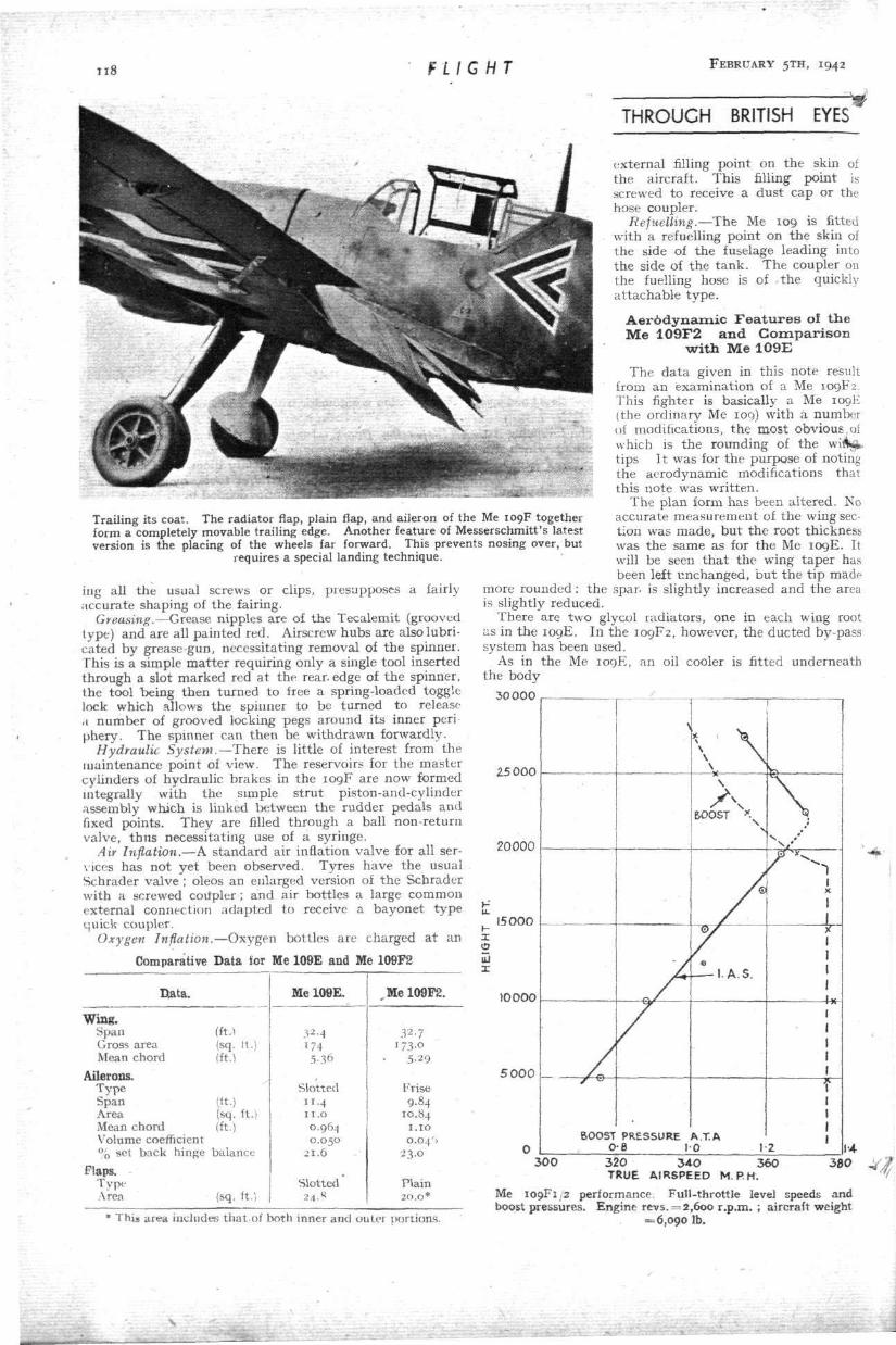
Trailing its coat. The radiator flap, plain flap, and aileron of the Me 109F together form a completely movable trailing edge. Another feature of Messerschmitt's latest version is the placing of the wheels far forward. This prevents nosing over, but
requires a special landing technique.
ing all the usual screws or clips, presupposes a fairly accurate shaping of the fairing.
Greasing.—Grease nipples are of the Tecalemit (grooved type) and are all painted red. Airscrew hubs are also lubricated by grease-gun, necessitating removal of the spinner. This is a simple ma t t e r requiring only a single tool inserted through a slot marked red a t the rear, edge of the spinner, the tool being then turned to free a spring-loaded toggle lock which allows the spinner to be turned to release ,1 number of grooved locking pegs around its inner periphery. The spinner can then be withdrawn forwardly.
Hydraulic System.—There is little of interest from the maintenance point of view. The reservoirs for the master cylinders of hydraulic brakes in the 109F are now formed integrally with the simple s t rut piston-and-cylinder assembly which is linked between the rudder pedals and fixed points. They are filled through a ball non-return valve, thus necessitating use of a syringe.
Air Inflation.—A standard air inflation valve for all services has not yet been observed. Tyres have the usual Schrader valve ; oleos an enlarged version of the Schrader with a screwed coitpler; and air bott les a large common external connection adapted to receive a bayonet type quick coupler.
Oxygen Inflation.—Oxygen bottles are charged a t an
Comparative Data tor Me 109E and Me 109F2
external filling point on the skin of the aircraft. This filling point is screwed to receive a dus t cap or the hose coupler.
Refuelling.—The Me 109 is fitted with a refuelling point on the skin of the side of the fuselage leading into the side of the t ank . The coupler on the fuelling hose is of the quickly a t tachable t ype .
A e r 6 d y n a m i c F e a t u r e s of t h e M e 1 0 9 F 2 a n d C o m p a r i s o n
w i t h M e 1 0 9 E
The da ta given in this note result from an examination of a Me 109F2. This fighter is basically a Me 109E (the ordinary Me 109) with a number of modifications, t he most obvious of which is the rounding of the wiAjt t ips I t was for the purpose of noting the aerodynamic modifications that this note was writ ten.
The plan form has been altered. No accurate measurement of the wing section was made , bu t the root thickness was the same as for the Me 109E. It will be seen t h a t the wing taper has been left unchanged, b u t the t ip made-
more rounded : the spar, is slightly increased and the area is slightly reduced.
There are two glycol radiators, one in each wing root as in the 109E. In the 109F2, however, the ducted by-pass system has been used.
As in the Me 109E, an oil cooler is fitted underneath the body
30000
25 000
20000
Eiata.
Wing. Span Cross area Mean chord
Ailerons. Type Span Area Mean chord Volume coefficient % set back
Flaps. Type Area
hinge
(ft.) (sq. it.) (ft.)
(it .) (sq. ft.) (ft.)
balance
(sq. ft.)
Me 109E.
32.4 174 5-36
Slotted 11.4 1 1 . a 0.964 0 . 0 5 0
2 1 . 6
Slotted 24 .«
,MelO0F2.
32.7 i73-o
5-29
Frise 9.84
10.84 1.10 0 .04 ' )
23.0
Plain 2 0 . 0 *
u. I -X o uJ 1
15000
10000
5 0 0 0 _
300 3 * 0 AIRSPEED M. P. H. M
This area includes that of both inner and outer portions.
Me 109F1/2 performance. Full-throttle level speeds and boost pressures. Engine revs. = 2,600 r.p.m. ; aircraft weight
=6,090 lb.

FEBRUARY 5TH, I942
T H R O U G H B R I T I S H EYES
Each flap is divided into an inboard and outboard p a r t ; the former consists of two port ions, which are capable.of simultaneous downward movement ( thus acting simply as a wing flap) or of opposite movements (acting as radiator flaps). The former motion takes place when the outer flaps are lowered. The la t ter motion is under the control of a thermosta t placed between the glycol header tank and the radiator .
It will be noticed t ha t both the flap span and area are less for the 109F2 than for the 109E.
The ailerons have been reduced in span and increased in chord from those of the 109E, the area, however, remaining almost una l te red : the t ype has been changed from slotted to Frise. Two diagrams give sectional views of the two types of ailerons.
The ailerons are fitted with small t abs for ground adjustment only, as in the 109E. Ex te rna l mass balance weights are fitted as in the 109E, bu t the ailerons do not come down with the flaps. . j the leading edge slats are of ra ther less span than for the
•rojE, bu t otherwise of similar design. A cantilever tailplane placed slightly below and for
ward of the original position replaces the braced tai lplane of the 109E ; it remains adjustable in flight. The elevators of the Me 109F2 are now over mass-balanced ; a t zero elevator angle the residual weight moment for both elevators abou t t h e hinge is of the order of 10 lb.-ft. tending to pull the elevators up . The elevators of the Me 109F1/2 , however, are identical with those of the 109E, both being approximately mass-balanced. The obvious difference between the two elevators is t ha t on the 109F2 the (lead) mass-balancing weight is screwed to the nose of the horn and can be easily detached, whereas on the 109F1/2 and. 109E the weight is enclosed in the metal skin of the horn.
The rudder area has been reduced from 8.1 to 7.5 sq. ft. The fin section has also been cambered (on the 109E the section was symmetrical) , presumably to reduce the amount of rudder needed on the climb.
The original a rmamen t of the 109E is replaced by a 15 mm. cannon firing down the airscrew shaft and two machine guns mounted in the usual position over the engine ; the only alteration from the 109E is, therefore, the omission of the wing guns. The fuselage seems to be the same as t h a t of the 109E, except t h a t external strengthening plates are screwed on to the sides of the fuselage near the rear as though to strengthen it in bending about the vertical axis.
„ B r i e f P e r f o r m a n c e T e s t s o n a M e 1 0 9 F 1 / 2 (DB 601N.)
Brief performance tests on a Me 109F covered the following poin ts : —
Determination of the full throt t le level speeds a t a series of heights from 5,000ft. to 27,500ft.
Full throt t le part ial climbs a t 5,000ft. and 20,000ft. The result so far obtained indicate t ha t the max imum
level speed is 371 m.p .h . T .A.S . ; it is obtained a t abou t 22,000ft., a l though boost pressure s tar ts falling off a t 19.000ft. The max imum rate of climb a t 5,000ft. is 3,320 f t . /min. , and a t 20,000ft. is 2,370 ft. /m in . Full throt t le snd 2,600 engine r .p .m. were used throughout .
All the above figures are applicable to the aircraft flying with its full service load, all-up weight 6,090 lb . , wing loading 35.2 l b . / s q . ft.
D e s c r i p t i o n of t h e A i r c r a f t
The Me 109F1 / 2 is a development of the Me 109E. The following are the more impor tan t differences between the two types which may affect performance: —
^ The wing plan form has been modified ; t he wing tips ^* are now rounded, with only slight changes in span and
area. The radiators , which are in t h e same position as on
the Me 109E, incorporate a boundary layer by -pas s ; th is
FLIGHT
4 0 0 0
119
3000
z
£ 2000
u u. O
« 1000
'Jn9 0 X.
HEIGHT 5000 FEET \ BOOST PRESSURE 1-36 ATA \
100 150 200 Vi E.A.S. M.P.H.
250 300
2
u u-o
<
2000
1000
0
A e
X
* K . HEIGHT 2 0 0 0 0 FEET \
BOOST PRESSURE 121 A T A . \
100 150 200 Vi E.A.S. M.P.H.
250 300
Full-throttle partial climbs of Me 109F at 5,000ft. and 20,000ft. Engine r.p.m. = 2,600 and aircraft weight 6,090 lb.
collects the boundary layer on the lower wing surface immediately ahead of the radiator , leads it round the
-top of the radiator and discharges it a t the trailing edge. This has allowed the radiators to be sunk farther into the wing and they now project only abou t 2.5m. The oil and coolant radiator flaps are thermostat ical ly controlled, bu t a pilot-controlled over-ride is provided to open the coolant radiator flaps.
The tail wheel now retracts . The braced tailplane has been replaced by a cantilever
tai lplane. The DB 601A engine installed in the Me 109E has
been replaced by a D B 601N. The chief differences between the two engines is t ha t piston tops are now flat instead of concave ; the compression rat io has thereby been increased from 6.9 to 7.9. Bench tests show t h a t t h e sea-level B . H . P . of the D B 601N is 1,085, compared wi th 985 for the D B 601A.
The air intake to the supercharge has been redesigned. The entry is farther out from the side of the fuselage than on the Me 109E, probably in order to obta in a greater ram effect.
The airscrew diameter has been reduced from 10.2ft. to 9.7ft., and the d iameter of the spinner has been increased. Tne petrol capaci ty of abou t 80 gallons is slightly less
than t h a t of the 109E. Provision is made to carry a jet t i -sonable t ank slung under the fuselage.
The airscrew has now been fitted with a constant-speed uni t of novel design. The r .p .m. a t which t h e airscrew

120 FLIGHT FEBRUARY 5TH, 1942
T H R O U G H B R I T I S H E Y E S - V
is controlled depend on the position of the throt t le lever. With the throt t le lever fully forward the unit is set to iontrol a t 2,600 r .p .m. ; when the throt t le lever is moved back the r .p .m. automatically fall an appropriate amount .
The constant-speed unit can be cut out by the pilot and the airscrew pitch controlled in the same way as on the Me 109E.
The norma] service load of the aeroplane with two M.G.17 machine-guns firing through the airscrew and one M.G.151 Tiring 20-mm. ammuni t ion is 6,090 lb . The aeroplane was flown a t this loading, which is about 500 lb. heavier than that of the Me 109E. The wing area of the Me 109F is 173 sq. ft., giving a wing-loadjng of 35.2 l b . / s q . ft., compared with 32.1 lb. / sq . ft. for the Me 109E.
Photographs of the aeroplane and of the radiator, with the flaps in their closed and open positions, are a t tached.
P r o g r a m m e of Tes t s The programme of tests covered the following po in t s : — Determinat ion of the position error curve. Measurement of full-throttle level speeds a t 2,600 engine
r .p .m. a t heights from 5,000ft. to 27,500ft. Par t ia l climbs a t 5,000ft. and 20,000ft. a t full throt t le
2,600 engine r.p.m. The following table gives the l imitations of the D B 601N
engine: —
•
5 minutes 30 minutes Continuous
Boost Ata.
I-34-M !-3 1.2
r.p.m.
2,600 2,400 2,300
At full throt t le the boost on the engine used was controlled a t 1.36 a ta . The tests were done a t full throt t le a t 2,600 engine r .p .m.
All the results were corrected to t h e take-off weight, 6,090 lb.
Resul t s Position error curve.—The aircraft was t imed a t various
speeds over a 7^ miles speed course in order to establish the position error.
Level Speeds-—The full-throttle level speeds and the corresponding boost pressures a t 2,600 engine r .p .m. are thown plotted against height in the chart . The engine was allowed to cool between each level so t h a t the thermostatically controlled radiator flaps would be closed.
Speeds were corrected on the density basis and boost on the half-and-half basis above the supercharged height. Below this height both were corrected on the pressure basis.
The maximum level speed with radiator flaps fully closed is 371 m.p .h . a t about 22,000ft.
An interesting feature is t h a t whereas the full-throttle height as indicated by boost pressure is 19,000ft., t he maximum level speed is obtained a t about 22,000ft. This phenomenon was also observed on the Me n o . Discus^jca of this apparen t anomaly is deferred unti l the DB.601 engine has been tested on the a l t i tude test-bed.
Partial Cl imbs Part ial climbs were done a t 5,000ft. and 20,000ft. The
rates of climb are shown plotted against E .A .S . in a graph The climbs were done a t full thrott le a t 2,600 engine r.p.m and have been corrected to the normal load of 6,090 lb.
At 5,000ft. the maximum rate of climb is 3,320 f t . /min. a t 165 m.p .h . E .A.S . , the boost pressure being 1.36 ata. At 20,000ft. the maximum rate of climb is 2,370 f t . /min. at 165 m.p .h . E .A.S . , the boost pressure being 121 ata .
The ra te of climb of the Me 109F a t 20,000ft. seems ra ther low in view of its reputed ceiling of about 40,000ft. It should be borne in mind, however, t h a t the engine gave trouble and t ha t the results contained in this note merely represent the best obtained under test . They do, however, give a useful guide to the minimum performance of the aircraft.
LORD TRENCHARD ON AIR POWER 'Air Must Dominate Strategy.
VISCOUNT T R E N C H A R D made a very impor tant speech in the House of Lords on Thursday, J anua ry 29th. He began by welcoming Lord Moyne's state
ment tha t in Russia, Britain and the Middle Eas t we well knew tha t the key to success lay in the balance of air power. He regretted t ha t in this war air power has often been used wrongly or not used a t all. One reason for our setback in the Pacific was t h a t 15 or r6 years ago the Government would not agree to make Singapore an air base in peace t ime. The Army and Navy only wanted aircraft t o spot 'for the big guns ; t he Air Service wanted to make it an air base as the best defence, and as it had possibilities of a great air offence from tha t base.
Lord Trenchard went on to s ta te certain facts which governed, and would always govern, the use of air power in war. They were of pa ramount importance bu t were still imperfectly understood by many critics. He thought t h a t most ol the public felt t ha t our setbacks in Norway, Greece and Crete were due to the air, and t h a t the Germans used their air more efficiently than we did. The same was felt by many as regards Malaya.
To sum up , tne setbacks and victories on both sides in this war had been due chiefly to air power. The Army, and the Navy in narrow waters, could not fight successfully without air cover, without air support , and without air superiority. Short-range fighters were always—and always would be—superior to long-range aircraft. The geographical position affected the air force more than it
affected the other services. We must choose, as far as possible, our batt leground.
If those vitally impor tan t considerations were overlooke'iH* or ignored it was no earthly use blaming the R . A . F . for lack of co-operation, bad organisation, or anyth ing else. Of course, the Royal Air Force authorit ies must draw at tent ion in Council to those factors when knowledge of them appeared to be lacking. B u t if, after making clear the facts—and they were facts which were universally recognised as fundamental by the Royal Air Force—their advice or warnings were not followed, then the true responsibility must rest elsewhere.
If their lordships believed what he had said, and tie believed t ha t nobody who was well informed could deny it, and if it was recognised by all, then it mean t t h a t air must dominate strategy. He did not mean t h a t air could win the war wi thout the Army and the Navy . I t could not, but it mus t dominate strategy. He asked their lordships to influence all with whom they came in contact to unders tand these very simple- facts, because on them bore the successful conclusion of this war.
ADVERTISED G O O D S THE fact that goods made of raw materials in short supply owing'.
to war conditions are advertised in this journal should not be ; taken as an indication thai they are necessarily available for export. \


![26.AH, THOSE BLACK EYES! (Akh, Eli Chiornye Glaza)DARK EYES (Ochi Chernye) Dark eyes, passionate eyes, Fiery and beautiful eyes; How I love you, how] fear you, Evidently I met you](https://img.dokumen.tips/doc/110x75/60adc1b670fe6b0a8514df75/26ah-those-black-eyes-akh-eli-chiornye-glaza-dark-eyes-ochi-chernye-dark.jpg)


![[PPT]PowerPoint Presentation - · Web view... (B – non-blue eyes, b – blue eyes) BB = non-blue eyes Bb = non-blue eyes bb = blue eyes Incomplete Dominance – Neither allele is](https://img.dokumen.tips/doc/110x75/5aae9c247f8b9a190d8c559f/pptpowerpoint-presentation-view-b-non-blue-eyes-b-blue-eyes-bb.jpg)