Embed Size (px)
Citation preview
IEEE TRANSACTIONS ON MAGNETICS, VOL. 43, NO. 4, APRIL 2007 1373
Three-Dimensional FEM Approach to ModelTwisted Wire Pair Cables
C. Buccella, M. Feliziani, and G. Manzi
Department of Electrical and Computer Engineering, University of L’Aquila, 67040 Poggio di Roio, Italy
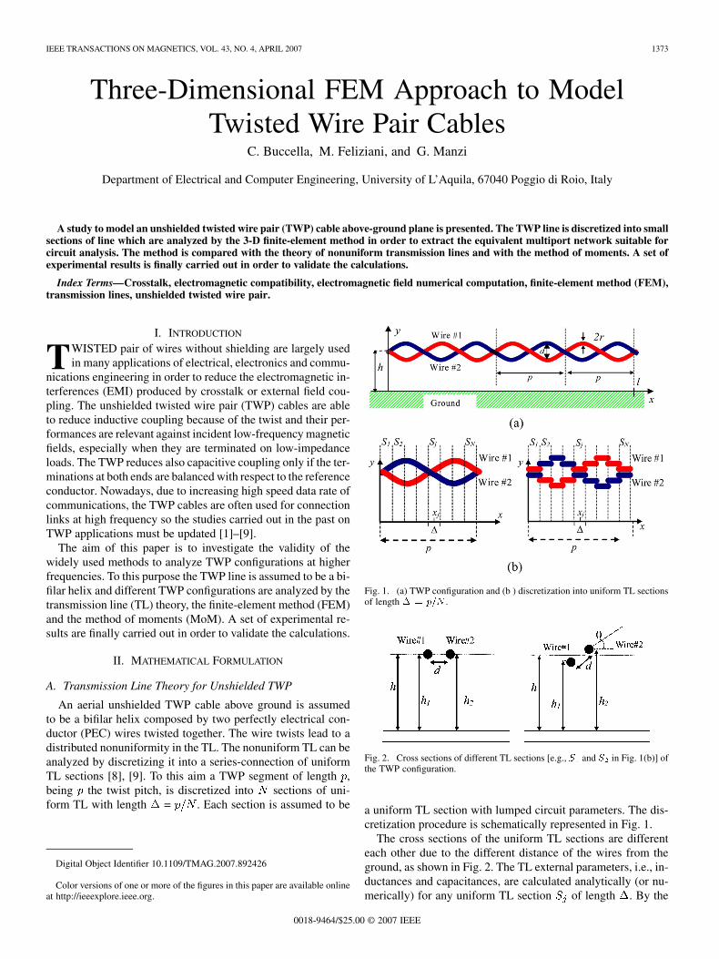
A study to model an unshielded twisted wire pair (TWP) cable above-ground plane is presented. The TWP line is discretized into smallsections of line which are analyzed by the 3-D finite-element method in order to extract the equivalent multiport network suitable forcircuit analysis. The method is compared with the theory of nonuniform transmission lines and with the method of moments. A set ofexperimental results is finally carried out in order to validate the calculations.
Index Terms—Crosstalk, electromagnetic compatibility, electromagnetic field numerical computation, finite-element method (FEM),transmission lines, unshielded twisted wire pair.
I. INTRODUCTION
TWISTED pair of wires without shielding are largely usedin many applications of electrical, electronics and commu-
nications engineering in order to reduce the electromagnetic in-terferences (EMI) produced by crosstalk or external field cou-pling. The unshielded twisted wire pair (TWP) cables are ableto reduce inductive coupling because of the twist and their per-formances are relevant against incident low-frequency magneticfields, especially when they are terminated on low-impedanceloads. The TWP reduces also capacitive coupling only if the ter-minations at both ends are balanced with respect to the referenceconductor. Nowadays, due to increasing high speed data rate ofcommunications, the TWP cables are often used for connectionlinks at high frequency so the studies carried out in the past onTWP applications must be updated [1]–[9].
The aim of this paper is to investigate the validity of thewidely used methods to analyze TWP configurations at higherfrequencies. To this purpose the TWP line is assumed to be a bi-filar helix and different TWP configurations are analyzed by thetransmission line (TL) theory, the finite-element method (FEM)and the method of moments (MoM). A set of experimental re-sults are finally carried out in order to validate the calculations.
II. MATHEMATICAL FORMULATION
A. Transmission Line Theory for Unshielded TWP
An aerial unshielded TWP cable above ground is assumedto be a bifilar helix composed by two perfectly electrical con-ductor (PEC) wires twisted together. The wire twists lead to adistributed nonuniformity in the TL. The nonuniform TL can beanalyzed by discretizing it into a series-connection of uniformTL sections [8], [9]. To this aim a TWP segment of length ,being the twist pitch, is discretized into sections of uni-form TL with length = . Each section is assumed to be
Digital Object Identifier 10.1109/TMAG.2007.892426
Color versions of one or more of the figures in this paper are available onlineat http://ieeexplore.ieee.org.
Fig. 1. (a) TWP configuration and (b ) discretization into uniform TL sectionsof length � = p=N .
Fig. 2. Cross sections of different TL sections [e.g., S and S in Fig. 1(b)] ofthe TWP configuration.
a uniform TL section with lumped circuit parameters. The dis-cretization procedure is schematically represented in Fig. 1.
The cross sections of the uniform TL sections are differenteach other due to the different distance of the wires from theground, as shown in Fig. 2. The TL external parameters, i.e., in-ductances and capacitances, are calculated analytically (or nu-merically) for any uniform TL section of length . By the
0018-9464/$25.00 © 2007 IEEE
1374 IEEE TRANSACTIONS ON MAGNETICS, VOL. 43, NO. 4, APRIL 2007
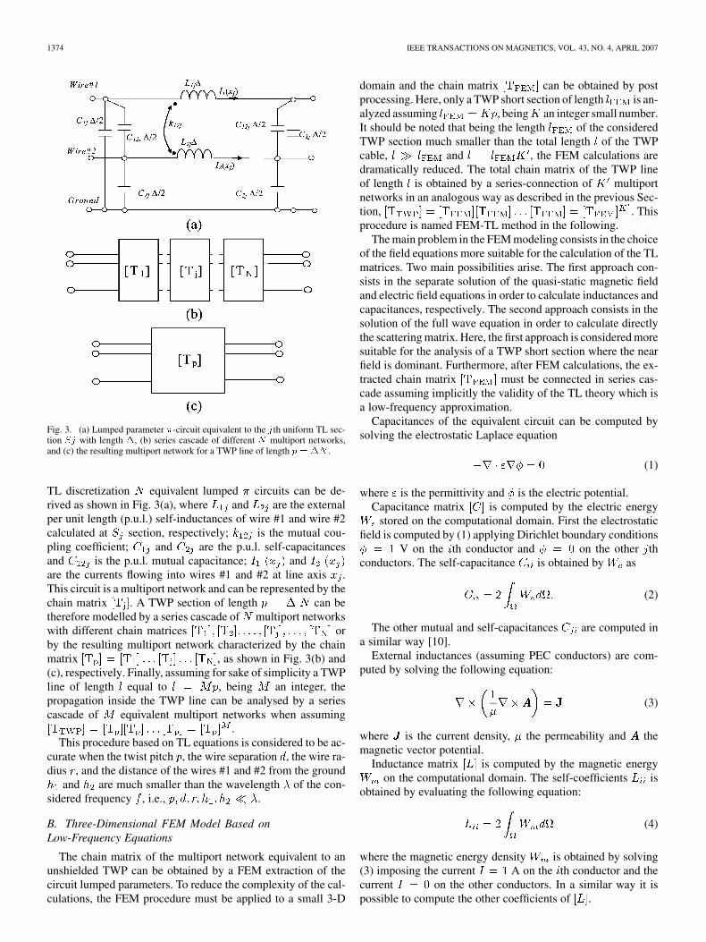
Fig. 3. (a) Lumped parameter �-circuit equivalent to the jth uniform TL sec-tion Sj with length �, (b) series cascade of different N multiport networks,and (c) the resulting multiport network for a TWP line of length p = �N .
TL discretization equivalent lumped circuits can be de-rived as shown in Fig. 3(a), where and are the externalper unit length (p.u.l.) self-inductances of wire #1 and wire #2calculated at section, respectively; is the mutual cou-pling coefficient; and are the p.u.l. self-capacitancesand is the p.u.l. mutual capacitance; andare the currents flowing into wires #1 and #2 at line axis .This circuit is a multiport network and can be represented by thechain matrix . A TWP section of length can betherefore modelled by a series cascade of multiport networkswith different chain matrices orby the resulting multiport network characterized by the chainmatrix , as shown in Fig. 3(b) and(c), respectively. Finally, assuming for sake of simplicity a TWPline of length equal to , being an integer, thepropagation inside the TWP line can be analysed by a seriescascade of equivalent multiport networks when assuming
.This procedure based on TL equations is considered to be ac-
curate when the twist pitch , the wire separation , the wire ra-dius , and the distance of the wires #1 and #2 from the ground
and are much smaller than the wavelength of the con-sidered frequency , i.e., .
B. Three-Dimensional FEM Model Based onLow-Frequency Equations
The chain matrix of the multiport network equivalent to anunshielded TWP can be obtained by a FEM extraction of thecircuit lumped parameters. To reduce the complexity of the cal-culations, the FEM procedure must be applied to a small 3-D
domain and the chain matrix can be obtained by postprocessing. Here, only a TWP short section of length is an-alyzed assuming , being an integer small number.It should be noted that being the length of the consideredTWP section much smaller than the total length of the TWPcable, and , the FEM calculations aredramatically reduced. The total chain matrix of the TWP lineof length is obtained by a series-connection of multiportnetworks in an analogous way as described in the previous Sec-tion, . Thisprocedure is named FEM-TL method in the following.
The main problem in the FEM modeling consists in the choiceof the field equations more suitable for the calculation of the TLmatrices. Two main possibilities arise. The first approach con-sists in the separate solution of the quasi-static magnetic fieldand electric field equations in order to calculate inductances andcapacitances, respectively. The second approach consists in thesolution of the full wave equation in order to calculate directlythe scattering matrix. Here, the first approach is considered moresuitable for the analysis of a TWP short section where the nearfield is dominant. Furthermore, after FEM calculations, the ex-tracted chain matrix must be connected in series cas-cade assuming implicitly the validity of the TL theory which isa low-frequency approximation.
Capacitances of the equivalent circuit can be computed bysolving the electrostatic Laplace equation
(1)
where is the permittivity and is the electric potential.Capacitance matrix is computed by the electric energy
stored on the computational domain. First the electrostaticfield is computed by (1) applying Dirichlet boundary conditions
V on the th conductor and on the other thconductors. The self-capacitance is obtained by as
(2)
The other mutual and self-capacitances are computed ina similar way [10].
External inductances (assuming PEC conductors) are com-puted by solving the following equation:
(3)
where is the current density, the permeability and themagnetic vector potential.
Inductance matrix is computed by the magnetic energyon the computational domain. The self-coefficients is
obtained by evaluating the following equation:
(4)
where the magnetic energy density is obtained by solving(3) imposing the current A on the th conductor and thecurrent on the other conductors. In a similar way it ispossible to compute the other coefficients of .
BUCCELLA et al.: 3-D FEM APPROACH TO MODEL TWISTED WIRE PAIR CABLES 1375
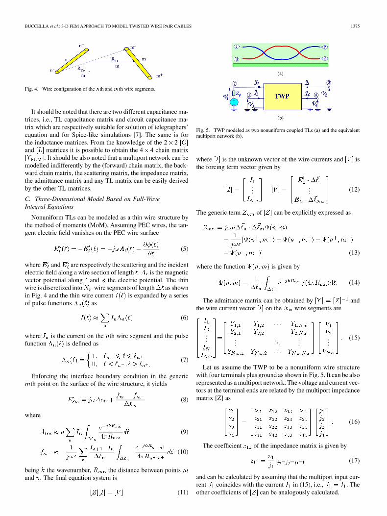
Fig. 4. Wire configuration of the nth andmth wire segments.
It should be noted that there are two different capacitance ma-trices, i.e., TL capacitance matrix and circuit capacitance ma-trix which are respectively suitable for solution of telegraphers’equation and for Spice-like simulations [7]. The same is forthe inductance matrices. From the knowledge of the 2 2and matrices it is possible to obtain the 4 4 chain matrix
. It should be also noted that a multiport network can bemodelled indifferently by the (forward) chain matrix, the back-ward chain matrix, the scattering matrix, the impedance matrix,the admittance matrix and any TL matrix can be easily derivedby the other TL matrices.
C. Three-Dimensional Model Based on Full-WaveIntegral Equations
Nonuniform TLs can be modeled as a thin wire structure bythe method of moments (MoM). Assuming PEC wires, the tan-gent electric field vanishes on the PEC wire surface
(5)
where and are respectively the scattering and the incidentelectric field along a wire section of length is the magneticvector potential along and the electric potential. The thinwire is discretized into wire segments of length as shownin Fig. 4 and the thin wire current is expanded by a seriesof pulse functions as
(6)
where is the current on the th wire segment and the pulsefunction is defined as
(7)
Enforcing the interface boundary condition in the genericth point on the surface of the wire structure, it yields
(8)
where
(9)
(10)
being the wavenumber, the distance between pointsand . The final equation system is
(11)
Fig. 5. TWP modeled as two nonuniform coupled TLs (a) and the equivalentmultiport network (b).
where is the unknown vector of the wire currents and isthe forcing term vector given by
...... (12)
The generic term of can be explicitly expressed as
(13)
where the function is given by
(14)
The admittance matrix can be obtained by andthe wire current vector on the wire segments are
... .... . .
......
(15)
Let us assume the TWP to be a nonuniform wire structurewith four terminals plus ground as shown in Fig. 5. It can be alsorepresented as a multiport network. The voltage and current vec-tors at the terminal ends are related by the multiport impedancematrix [Z] as
(16)
The coefficient of the impedance matrix is given by
(17)
and can be calculated by assuming that the multiport input cur-rent coincides with the current in (15), i.e., . Theother coefficients of can be analogously calculated.

1376 IEEE TRANSACTIONS ON MAGNETICS, VOL. 43, NO. 4, APRIL 2007
Fig. 6. Electrical configuration of (a) the unshielded TWP cable and (b) exper-imental setup.
Fig. 7. Mesh of the reduced FEM domain.
TABLE IFEM CALCULATION OF CAPACITANCES AND INDUCTANCES
III. APPLICATIONS
In order to investigate the effect of the pitch length on thecable performances, two different TWP configurations (or testcases) have been examined by different numerical and experi-mental techniques. The considered aerial unshielded TWP cablehas a fixed geometrical configuration (see Fig. 1) with length
cm, height cm, wire radius mm, wireseparation cm, while the twist pitch is variable with twodifferent values cm and cm, referred respectivelyto the two test cases labeled 1 TWP and 2 TWP. The exam-ined electrical configuration is shown in Fig. 6(a) and the ex-perimental setup is shown in Fig. 6(b).
A 3-D FEM study has been carried out by analyzing the twotest cases in a reduced 3-D domain of fixed length (10 cm), asshown schematically in Fig. 7. After 3-D FEM calculations,the lumped parameters of the considered TWP section havebeen extracted as shown in Table I. These parameters havebeen introduced in a lumped parameter circuit (i.e., multiportnetwork) and a Spice simulation has been carried out. The3-D FEM-TL method has been applied to the two test casesas shown in Fig. 8(a) where the scattering parameter vsfrequency is plotted for 10–300 MHz. The same resultshave been obtained by the TL method [see Fig. 8(b)], the MoMapproach [see Fig. 8(c)] and by network analyzer measure-ments [see Fig. 8(d)]. It should be noted that the values areslightly different for the two different test cases, but the curvesin Fig. 8 are quite similar due to the decibel scale.
Fig. 8. Scattering parameterS calculated and measured by different methodsin the frequency range 10–300 MHz. (a) 3-D FEM-TL method, (b) TL method,(c) MoM method, and (d) measurements.
IV. CONCLUSION
Different procedures have been applied to compute the equiv-alent multiport network of an unshielded twisted pair cable: thefirst based on transmission line theory, the second based on 3-DFEM model based on low-frequency field equations and the lastbased on 3-D model based on full-wave integral equations. Anexperimental setup was built and a comparison between the nu-merical and experimental results has been performed.
REFERENCES
[1] Taylor and J. P. Castillo, “On the response of a terminated twisted-wire cable excited by a plane-wave electromagnetic field,” IEEE Trans.Electromagn. Compat., vol. EC-22, pp. 16–19, Feb. 1980.
[2] R. Paul and J. W. McKnight, “Prediction of crosstalk involving twistedpairs of wires—Part I: A transmission-line model for twisted-wirepairs,” IEEE Trans. Electromagn. Compat., vol. EC-21, pp. 92–105,May 1979.
[3] J. E. Schutt-Aine, “High-frequency characterization of twisted-pair ca-bles,” IEEE Trans. Commun., vol. 49, no. 4, pp. 598–601, Apr. 2001.
[4] K. Chamberlin, K. Komisarek, and K. Sivaprasad, “A method-of-mo-ments solution to the twisted-pair transmission line,” IEEE Trans. Elec-tromagn. Compat., vol. 37, no. 1, pp. 121–126, Feb. 1995.
[5] J. A. B. Faria and M. V. G. das Neves, “Analysis of the helical twisted-wire pair running above ground: Transfer function evaluation,” IEEETrans. Electromagn. Compat., vol. 45, no. 2, pp. 449–453, May 2003.
[6] Gavrilakis, A. P. Duffy, K. G. Hodge, and A. J. Willis, “Partial capac-itance calculation for shielded twisted pair cables,” IEEE Trans. Elec-tromagn. Compat., vol. 46, no. 2, pp. 299–302, May 2004.
[7] C. R. Paul, Introduction to Electromagnetic Compatibility. Hoboken,NJ: Wiley, 2006.
[8] S. Caniggia, M. Feliziani, G. Manzi, and F. Maradei, “Time domainanalysis of lossy shielded cables by CAD circuit simulators,” in Proc.2004 IEEE Int. Symp. EMC, Aug. 9–13, 2004, vol. 3, pp. 952–957.
[9] C. Buccella, M. Feliziani, F. Maradei, and G. Manzi, “Prediction ofvoltage and current propagation in twisted wire pairs (TWPs) by a cir-cuit model,” in IEEE Int. Symp. on Elecromag. Compat., Chicago, IL,Aug. 8–12, 2005, vol. 1, pp. 51–55.
[10] S. Cristina and M. Feliziani, “A finite element technique for multicon-ductor cable parameters calculation,” IEEE Trans. Magn., vol. 25, no.4, pp. 2986–2988, Jul. 1989.
Manuscript received April 24, 2006 (e-mail: [email protected]).
![CFI 1 Twisted Pair 100 Mbit/s Ethernet (1TPCE)ieee802.org/3/cfi/0314_2/CFI_02_0314.pdfCFI 1 Twisted Pair 100 Mbit /s Ethernet (1TPCE) 1 Twisted Pair 100 [C] Mbit/s Ethernet Call for](https://img.dokumen.tips/doc/110x75/5ace48097f8b9a6c6c8ba026/cfi-1-twisted-pair-100-mbits-ethernet-1tpce-1-twisted-pair-100-mbit-s-ethernet.jpg)
![PERTEMUAN 3 MEDIA & KONEKTOR€¦ · [3] Media Kabel [a] Twisted Pair [i]. Unshielded Twisted Pair (UTP) [ii]. Shielded Twisted Pair (STP)](https://img.dokumen.tips/doc/110x75/612d4b2b1ecc515869421968/pertemuan-3-media-konektor-3-media-kabel-a-twisted-pair-i-unshielded.jpg)