Embed Size (px)
Citation preview

Relion®. The perfect choice for every application.The widest range of products for power systems protection, control, measurement and supervision. Interoperable and future-proof solutions designed to implement the core values of the IEC 61850 standard. ABB’s leading-edge technology, global application knowledge and experienced support network ensures complete confidence that your system performs reliably - in any situation.
This webinar brought to you by The Relion® Product Family Next Generation Protection and Control IEDs from ABB
August 18,
2014
| Slide 1
© ABB Group

ABB is pleased to provide you with technical information regarding protective
relays. The material included is not intended to be a complete presentation of
all potential problems and solutions related to this topic. The content is
generic and may not be applicable for circumstances or equipment at any
specific facility. By participating in ABB's web-based Protective Relay School,
you agree that ABB is providing this information to you on an informational
basis only and makes no warranties, representations or guarantees as to the
efficacy or commercial utility of the information for any specific application or
purpose, and ABB is not responsible for any action taken in reliance on the
information contained herein. ABB consultants and service representatives
are available to study specific operations and make recommendations on
improving safety, efficiency and profitability. Contact an ABB sales
representative for further information.
ABB Protective Relay School Webinar SeriesDisclaimer
August 18,
2014
| Slide 2
© ABB Group
Generator Protection FundamentalsJack ChangAug 19 , 2014
ABB Protective Relay School Webinar Series

Presenter
August 18,
2014
| Slide
4
©ABB
Jack Chang
Jack Chang is the regional technical manager for ABB Inc. in
the Substation Automation business serving customers in
Canada and northern regions. He provides engineering,
commissioning and troubleshooting support to customers
applying ABB’s high-voltage protective and automation
devices. Prior to joining ABB, Jack worked as a substation
P&C project engineer in two specialized consulting firms (now
ABB and Quanta Services, respectively) and also as an
engineering consultant to a public owned utility in their
transmission expansion and upgrade projects. Jack is a
registered professional engineer in the province of Alberta,
Canada.

Learning objectives
Power Generation fundamentals
Generator Faults
Generator Abnormal Conditions
Modern Generator Protective IED Capabilities
Typical Generator Protection Functions
August 18,
2014
| Slide 5
© ABB Group

Standards
C37.101: Guide for AC Generator Ground Protection
C37.102: Guide for AC Generator Protection
IEEE Tutorial On The Protection of Synchronous Generator
(PSRC)
August 18,
2014
| Slide 6
© ABB Group

EXCITATION
SYSTEM
CONTROL
ROOM
CONTROL
SYSTEMS
STEP UP
TRANSFORMERHV SYSTEM
STARPOINT
CUBICLE
HV- SUBSTATION
MV DRIVES
SYNCHRONIZATION
TURBINE
GOVERNOR
1
1
Power Island
G
EXCITATION
TRANS-
FORMERTURBINE
MV SWITCHGEAR
GENERATOR
CIRCUIT
BREAKER
PT’s
CT’s
SA’s
UNIT
PROTECTION
AUXILIARY
TRANS-
FORMER
LV DRIVES
INSTRUMENTATION
Temperature
Pressure
LV
SWITCHGEAR
LV
MOTORS
COMMUNICATION
ACTUATOR
ON-OFF,
Controlled
ANALYZERS
MV
MOTORS
Power station is the most complex part of the power system
August 18,
2014
| Slide 7
© ABB Group

Typical Parts of a Power Plant
G
HV Substation
Power plant
Busbar in HV Substation
HV - Breaker
Main Transformer Auxiliary Transformer
Generator Breaker
Excitation Transformer
Excitation System
Field Circuit Breaker
Turbine valve
Turbine - Generator
Earthing System
August 18,
2014
| Slide 8
© ABB Group

Different power plants electrical equipment layouts
G G G
GG G
August 18,
2014
| Slide 9
© ABB Group

Damage to the stator core in case of earth-fault
Practically all unit
connected generators are
high-impedance earthed
Only industrial generators
may be low-impedance
earthed
August 18,
2014
| Slide 10
© ABB Group

Stator winding earthing practices
G
Isolated
G
Resistive
Grounded
~ 1kΩR
G
Grounding
Transformer
(Neutral)
~ 0.5ΩR
G
Grounding
Transformer
(Terminal)~ 3.0ΩR
August 18,
2014
| Slide 11
© ABB Group

Possible faults
Stator Earth Faults
Rotor Earth Faults
Stator Short Circuits
Stator/Rotor Interturn faults
Unit transformer faults
External faults
August 18,
2014
| Slide 12
© ABB Group

overcurrent/overload
unbalanced load
overtemperature
over- and undervoltage
over- and underexcitation
over- and underfrequency
over-fluxing
asynchronous running
out of step
generator motoring
failures in the machine control system (i.e. AVR or governor failure)
failures in the machine cooling system
failures in the primary equipment (i.e. breaker head flashover)
open phase
Abnormal operating condition
August 18,
2014
| Slide 13
© ABB Group

Allocation of protection functions
87G/87O Differential
59 Over-voltage
24V/Hz over-fluxing
49S Stator over-load
21/51V Voltage/over-current
64S Earth fault stator
Inter-turn
50AE Accidental energizing
Turbine
Rotor Stator
32 Reverse power
81O/U Frequency
46 Unbalance
40 Loss of excitation
78 Pole slipping
64R Earth fault rotor
49R Rotor overload
August 18,
2014
| Slide 14
© ABB Group

Generator protection
GI
U
CV GAPC
64R Re<
STEF PHIZ
59THD U3d/N
GEN PDIF
87G 3Id/I
SA PTUF
81 f<
SA PTOF
81 f>
SDD RFUF
60FL
OEX PVPH
24 U/f>
UV2 PTUV
27 3U<
OV2 PTOV
59 3U>
Option
REG 670*1.2 – A20
Gen Diff + Back-up 12AI
ZMH PDIS
21 Z<
LEX PDIS
40 Φ<
GUP PDUP
37 P<
GOP PDOP
32 Pß
ROV2 PTOV
59N 3Uo>
OC4 PTOC
51/67 3I->
CC RBRF
50BF 3I> BF
NS2 PTOC
46 I2>
TR PTTR
49 Ith
PSP PPAM
78 Ucos
+ RXTTE4
AEG GAPC
50AE U/I>
CV MMXU
Meter.
ROV2 PTOV
59N UN>
YY
<
CCS RDIF
87CT I2d/I
SDE PSDE
32N P0->
CV GAPC
51/27 U</I>
SES RSYN
25
CV GAPC
51V I>/U
PH PIOC
50 3I>>
CC RPLD
52PD PD
OC4 PTOC
51/67 3I>
Other functions available from the function library
T2W PDIF
87T 3Id/I
HZ PDIF
87 IdN
Function alternatives for 87G/GEN PDIF
STTI PHIZ
64S RSE<
ROTI PHIZ
64R RRE<
August 18,
2014
| Slide 15
© ABB Group

Generator protection with 87T (87O)
GI
U
CV GAPC
64R Re<
ROV2 PTOV
59N UN>
STEF PHIZ
59THD U3d/N
SA PTUF
81 f<
SA PTOF
81 f>
SDD RFUF
60FL
OEX PVPH
24 U/f>
UV2 PTUV
27 3U<
OV2 PTOV
59 3U>
CV MMXU
Meter.
Option
REG 670*1.2 – A20
Overall Diff + Back-up 12AI
ZMH PDIS
21 Z<
LEX PDIS
40 Φ<
GUP PDUP
37 P<
GOP PDOP
32 Pß
ROV2 PTOV
59N 3Uo>
OC4 PTOC
50/51 3I>
CC RBRF
50BF 3I> BF
NS2 PTOC
46 I2>
TR PTTR
49 Ith
PSP PPAM
78 Ucos
AEG GAPC
50AE U/I>
+ RXTTE4
T2W PDIF
87O 3Id/I
YY
<
Y
DUni
t Tra
fo
August 18,
2014
| Slide 16
© ABB Group

Older type of design:
M1 and M2 with
different function
allocations
Function allocations with older generation relays
August 18,
2014
| Slide 17
© ABB Group

Complete Protection Scheme
Generator M1 & M2 protection
Two identical IEDs with 87G
(low/high impedance based)
Complete Unit Protection for Smaller
Machines
One with 87G
One with 87T or 87O
August 18,
2014
| Slide 18
© ABB Group

Generator protection & optional transformer protection
GI
U
CV GAPC
64R Re<
ROV2 PTOV
59N UN>
GEN PDIF
87G 3Id/I
SA PTUF
81 f<
SA PTOF
81 f>
SDD RFUF
60FL
Option
REG 670*1.2 – B30
Gen Diff + Back-up 24AI
ZMH PDIS
21 Z<
LEX PDIS
40 Φ<
GUP PDUP
37 P<
GOP PDOP
32 Pß
OC4 PTOC
51/67 3I->
CC RBRF
50BF 3I> BF
NS2 PTOC
46 I2>
TR PTTR
49 Ith
PSP PPAM
78 Ucos
AEG GAPC
50AE U/I>
+ RXTTE4
STEF PHIZ
59THD U3d/N
REF PDIF
87N IdN/I
Auxiliary Bus
OC4 PTOC
50/51 3I>
OC4 PTOC
50/51 3I>
CC RBRF
50BF 3I> BF
EF4 PTOC
51N IN>
OC4 PTOC
50/51 3I>
Main Protection
Back-up Protection
ROV2 PTOV
59N 3Uo>
T3W PDIF
87T 3Id/I
CV MMXU
Meter.
OEX PVPH
24 U/f>
UV2 PTUV
27 3U<
OV2 PTOV
59 3U>
ROV2 PTOV
59N 3Uo>
YY
<
YY
<
Y
D
Unit Trafo
Aux
iliar
y T
rafo
Exc
itatio
n T
rafo
SDE PSDE
32N P0->
CCS RDIF
87CT I2d/I
CV GAPC
51/27 U</I>
SES RSYN
25
CV GAPC
51V I>/U
PH PIOC
50 3I>>
CC RPLD
52PD PD
Other functions available from the function library
T2W PDIF
87T 3Id/I
STTI PHIZ
64S RSE<
ROTI PHIZ
64R RRE<
August 18,
2014
| Slide 19
© ABB Group

Complete generator-transformer unit protection
GI
U
CV GAPC
64R Re<
STEF PHIZ
59THD U3d/N
TR PTTR
49 Ith
SA PTUF
81 f<
CV MMXU
Meter.
EF4 PTOC
50N/51N IN>
REF PDIF
87N IdN/I
OV2 PTOV
59 3U>
T3W PDIF
87O 3Id/I
REG 670*1.2 – C30
T2W PDIF
87T 3Id/I
ROV2 PTOV
59N 3Uo>
Generator and block transformer protection 24AI
NS2 PTOC
46 I2>
TR PTTR
49 Ith
SDD RFUF
60FL
SDD RFUF
60FL
ZMH PDIS
21 Z<
LEX PDIS
40 Φ<
GUP PDUP
37 P<
GOP PDOP
32 Pß
PSP PPAM
78 Ucos
Option
SA PTOF
81 f>
OEX PVPH
24 U/f>
UV2 PTUV
27 3U<
OV2 PTOV
59 3U>
OC4 PTOC
50/51 3I>
OC4 PTOC
50/51 3I>
CC RBRF
50BF 3I> BF
GEN PDIF
87G 3Id/I
+ RXTTE4
ROV2 PTOV
59N UN>
CC RBRF
50BF 3I> BF
OC4 PTOC
51/67 3I->
AEG GAPC
50AE U/I>
CV MMXU
Meter.
YY
<
ROV2 PTOV
59N 3Uo>
YY
<
YY
<
Y
DUni
t Tra
fo
Grounding
Transformer
SDE PSDE
32N P0->
CV GAPC
51/27 U</I>
SES RSYN
25
CV GAPC
51V I>/U
PH PIOC
50 3I>>
CC RPLD
52PD PD
OC4 PTOC
51/67 3I>
Other functions available from the function library
CCS RDIF
87CT I2d/I
STTI PHIZ
64S RSE<
ROTI PHIZ
64R RRE<
August 18,
2014
| Slide 20
© ABB Group

Generator terminal short circuit
August 18,
2014
| Slide 21
© ABB Group
E”
E’
Ed
Xd” Xd’ Xd
Et
Xd” - Subtransient Reactance
Xd’ - Transient Reactance
Xd - Synchronous Reactance
The fault current from the
generator change during fault
sequence
Change of generator reactance
Xd’’ -> Xd’ -> Xd
Dependent of the excitation
system

Stator short circuit
Consequence of stator short circuit
Insulation, windings and stator core can be damaged
Large forces, caused by large fault currents, can give
damage to other components in the plant
Risk of explosion and fire
Mechanical stress on generator- and turbine shafts
August 18,
2014
| Slide 22
© ABB Group

Detection of stator short circuits
Protection functions
Generator differential protection
Block (unit) differential protection
Directional negative sequence overcurrent protection
Under impedance protection
Phase overcurrent protection (sometimes not effective)
Voltage dependent phase overcurrent protection
Under voltage protection
Phase overcurrent protection of the block transformer
August 18,
2014
| Slide 23
© ABB Group

Generator differential protection
Unstabilized differential protection level
Stabilized differential protection level
Harmonic blocking
Negative sequence unrestrained
Combination: bias differential and negative sequence
internal/external discriminator; increases speed and
security
Negative sequence sensitive differential protection
August 18,
2014
| Slide 24
© ABB Group

Differential protection characteristics
restrain current
[gen. rated curr.]
0 1 2 3 4 5 6
operate current
[gen. rated curr.]
0
1
2
3
4
5
IdMin
Section 1
Operate
conditionally
D Ioperate
slope = ---------------- * 100 %
D Irestrain
UnrestrainedLimit
Section 2 Section 3
The restrained
characteristic
is defined by
the settings:
******************
1. IdMin
2. EndSection1
3. EndSection2
4. SlopeSection2
5. SlopeSection3
SlopeSection2
SlopeSection3
EndSection1
EndSection2
Restrain
Operate
unconditionally
August 18,
2014
| Slide 25
© ABB Group

Generator unit (overall) differential protection
Identical to transformer differential protection
Zero sequence current elimination
Vector group compensation
Transformer ratio compensation
Unstabilized differential protection
Stabilized differential protection
Harmonic blocking
Waveform blocking
Negative sequence unrestrained
Combination: bias differential and negative sequence internal/external discriminator
Negative sequence sensitive differential protection
August 18,
2014
| Slide 26
© ABB Group

Phase to phase fault in the stator winding
GU
U
STEF PHIZ
59THD U3d/N
TR PTTR
49 Ith
SA PTUF
81 f<
EF4 PTOC
50N/51N IN>
REF PDIF
87N IdN/I
T3W PDIF
87O 3Id/I
REG 670*1.2
ROV2 PTOV
59N 3Uo>
NS2 PTOC
46 I2>
TR PTTR
49 Ith
SDD RFUF
60FL
ZMH PDIS
21 Z<
LEX PDIS
40 Φ<
GUP PDUP
37 P<
GOP PDOP
32 Pß
PSP PPAM
78 Ucos
SA PTOF
81 f>
OEX PVPH
24 U/f>
UV2 PTUV
27 3U<
OV2 PTOV
59 3U>
OC4 PTOC
50/51 3I>
OC4 PTOC
50/51 3I>
CC RBRF
50BF 3I> BF
GEN PDIF
87G 3Id/I
ROV2 PTOV
59N UN>
CC RBRF
50BF 3I> BF
OC4 PTOC
51/67 3I->
AEG GAPC
50AE U/I>
CV MMXU
Meter.
+ REX060, REX061
STTI PHIZ
64S RSE<
ROTI PHIZ
64R RRE<
+ REX060
CV MMXU
Meter.
YY
<
Y
D
YY
<
Uni
t Tra
fo
VT
Endangering condition
Overcurrent
Protected object
Stator winding
Consequences
Heating
Forces
Smelted stator core
Main Protection Function
Reserve Protection Function
August 18,
2014
| Slide 27
© ABB Group

Endangering condition
Overcurrent
Protected object
XFMR, bus work
Consequences
Heating
Forces
Smelted trafo core
Phase to phase fault in the XFMR, and bus work
Main Protection Function
Reserve Protection Function
GU
U
STEF PHIZ
59THD U3d/N
TR PTTR
49 Ith
SA PTUF
81 f<
EF4 PTOC
50N/51N IN>
REF PDIF
87N IdN/I
T3W PDIF
87O 3Id/I
REG 670*1.2
ROV2 PTOV
59N 3Uo>
NS2 PTOC
46 I2>
TR PTTR
49 Ith
SDD RFUF
60FL
ZMH PDIS
21 Z<
LEX PDIS
40 Φ<
GUP PDUP
37 P<
GOP PDOP
32 Pß
PSP PPAM
78 Ucos
SA PTOF
81 f>
OEX PVPH
24 U/f>
UV2 PTUV
27 3U<
OV2 PTOV
59 3U>
OC4 PTOC
50/51 3I>
OC4 PTOC
50/51 3I>
CC RBRF
50BF 3I> BF
GEN PDIF
87G 3Id/I
ROV2 PTOV
59N UN>
CC RBRF
50BF 3I> BF
OC4 PTOC
51/67 3I->
AEG GAPC
50AE U/I>
CV MMXU
Meter.
+ REX060, REX061
STTI PHIZ
64S RSE<
ROTI PHIZ
64R RRE<
+ REX060
CV MMXU
Meter.
YY
<
Y
D
YY
<
Uni
t Tra
fo
VT
August 18,
2014
| Slide 28
© ABB Group
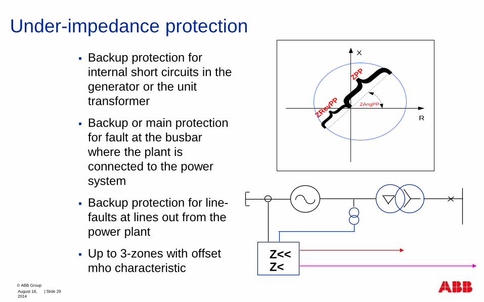
Under-impedance protection
Backup protection for
internal short circuits in the
generator or the unit
transformer
Backup or main protection
for fault at the busbar
where the plant is
connected to the power
system
Backup protection for line-
faults at lines out from the
power plant
Up to 3-zones with offset
mho characteristic
ZAngPP
}}
ZPP
ZRevPP
X
R
ANSI 21Z<<Z<
August 18,
2014
| Slide 29
© ABB Group
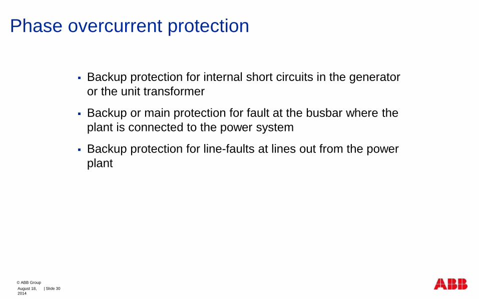
Phase overcurrent protection
Backup protection for internal short circuits in the generator
or the unit transformer
Backup or main protection for fault at the busbar where the
plant is connected to the power system
Backup protection for line-faults at lines out from the power
plant
August 18,
2014
| Slide 30
© ABB Group

External short circuit
Before Fault
First period of Fault
After 0.4 s
I>
August 18,
2014
| Slide 31
© ABB Group

Voltage controlled phase overcurrent protection
August 18,
2014
| Slide 32
© ABB Group

External faults
Main Protection Function
Reserve Protection Function
GU
U
STEF PHIZ
59THD U3d/N
TR PTTR
49 Ith
SA PTUF
81 f<
EF4 PTOC
50N/51N IN>
REF PDIF
87N IdN/I
T3W PDIF
87O 3Id/I
REG 670*1.2
ROV2 PTOV
59N 3Uo>
NS2 PTOC
46 I2>
TR PTTR
49 Ith
SDD RFUF
60FL
ZMH PDIS
21 Z<
LEX PDIS
40 Φ<
GUP PDUP
37 P<
GOP PDOP
32 Pß
PSP PPAM
78 Ucos
SA PTOF
81 f>
OEX PVPH
24 U/f>
UV2 PTUV
27 3U<
OV2 PTOV
59 3U>
OC4 PTOC
50/51 3I>
OC4 PTOC
50/51 3I>
CC RBRF
50BF 3I> BF
GEN PDIF
87G 3Id/I
ROV2 PTOV
59N UN>
CC RBRF
50BF 3I> BF
OC4 PTOC
51/67 3I->
AEG GAPC
50AE U/I>
CV MMXU
Meter.
+ REX060, REX061
STTI PHIZ
64S RSE<
ROTI PHIZ
64R RRE<
+ REX060
CV MMXU
Meter.
YY
<
Y
D
YY
<
Uni
t Tra
fo
VT
Endangering condition
Overcurrent
Protected object
External power system
parts.
Consequences
Heating
Forces
Mechanical damages
August 18,
2014
| Slide 33
© ABB Group

Stator earth fault
Damages on the stator iron
Increased voltage on “healthy phases”
Small fault currents
Sensitivity requirements on fault clearance
The fault resistance is normally low at stator earth fault
The residual voltage and earth fault current is highly
dependent on fault location in the generator
August 18,
2014
| Slide 34
© ABB Group

Voltage based 95 % stator earth fault protection
Generator Step-up transformer
Uo
Neutral point voltage transformer used
to measure Uo voltage
_
3
Gen Ph PhU
Uo
Voltage Uo has the following primary value for
the solid Ph-Gnd fault at generator HV terminals
August 18,
2014
| Slide 35
© ABB Group

Current based 95 % stator earth fault protection
Generator Step-up transformer
I>10/1A
Neutral point current measurement
August 18,
2014
| Slide 36
© ABB Group

Why 95 % and 100% stator ground fault protection?
0%
100%
Protected zone
is approximately
95%
Last 5% is
NOT
protected
August 18,
2014
| Slide 37
© ABB Group
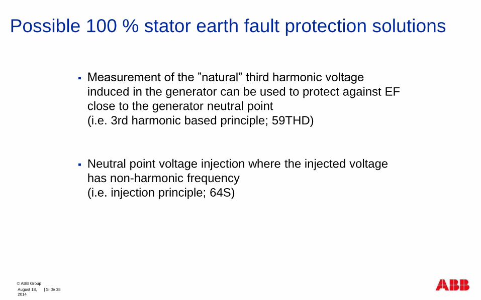
Possible 100 % stator earth fault protection solutions
Measurement of the ”natural” third harmonic voltage
induced in the generator can be used to protect against EF
close to the generator neutral point
(i.e. 3rd harmonic based principle; 59THD)
Neutral point voltage injection where the injected voltage
has non-harmonic frequency
(i.e. injection principle; 64S)
August 18,
2014
| Slide 38
© ABB Group

3rd harmonic 100% stator ground fault
Simplest approach :
3rd harmonic under-voltage in the neutral (i.e. U3N<)
3rd harmonic over-voltage at generator terminals (i.e. U3T>)
Possible problems:
Generator start-up
Generator shut-down
Different generator loading
3rd harmonic differential principle
3 3 3N T NU U Beta U
August 18,
2014
| Slide 39
© ABB Group

3rd harmonic based 100% stator earth-fault
x E3
Rf step-upunit
transformer
TCB 2(1-x) E3
x 1 - x
Neutral point fundamental frequencyover- voltage protection 10 – 100 %
Differential0 – 30 %
CB 1 may not exist
RN
NCB 1
stator winding
UT3UN3
Samples of the neutral voltagefrom which thefundamental-and 3rd harmonic voltages are filtered out
Samples of the terminal voltagefrom which the3rd harmonicvoltage is filtered out
x E3
Rf step-upunit
transformer
TCB 2(1-x) E3
x 1 - x
Neutral point fundamental frequencyover- voltage protection 10 – 100 %
3rd Diff.0 – 30 %
CB 1 may not exist
100 %
RN
NNCB 1
stator winding
Samples of the neutral voltagefrom which thefundamental-and 3rd harmonic voltages are filtered out
Samples of the terminal voltagefrom which the3rd harmonicvoltage is filtered out
August 18,
2014
| Slide 40
© ABB Group

Stator injection
Generator
ICT
PCM600 2.3
PC
ICT
REX060
(Injection Unit)
ALWAYS requiredREG670
RIM
SIM
PS
M
REX062 (Shunt Resistor Unit)
SOMETIMES required
Generator Protection Cubicle
STATOR
ROTOR
VT or GT
August 18,
2014
| Slide 41
© ABB Group

Earth fault in the stator winding
Main Protection Function
Reserve Protection Function
GU
U
STEF PHIZ
59THD U3d/N
TR PTTR
49 Ith
SA PTUF
81 f<
EF4 PTOC
50N/51N IN>
REF PDIF
87N IdN/I
T3W PDIF
87O 3Id/I
REG 670*1.2
ROV2 PTOV
59N 3Uo>
NS2 PTOC
46 I2>
TR PTTR
49 Ith
SDD RFUF
60FL
ZMH PDIS
21 Z<
LEX PDIS
40 Φ<
GUP PDUP
37 P<
GOP PDOP
32 Pß
PSP PPAM
78 Ucos
SA PTOF
81 f>
OEX PVPH
24 U/f>
UV2 PTUV
27 3U<
OV2 PTOV
59 3U>
OC4 PTOC
50/51 3I>
OC4 PTOC
50/51 3I>
CC RBRF
50BF 3I> BF
GEN PDIF
87G 3Id/I
ROV2 PTOV
59N UN>
CC RBRF
50BF 3I> BF
OC4 PTOC
51/67 3I->
AEG GAPC
50AE U/I>
CV MMXU
Meter.
+ REX060, REX061
STTI PHIZ
64S RSE<
ROTI PHIZ
64R RRE<
+ REX060
CV MMXU
Meter.
YY
<
Y
D
YY
<
Uni
t Tra
fo
VT
Endangering condition
Overvoltage in two healthy
phases
Voltage in the star point
Relatively small earth fault
current
Protected object
Stator winding
Consequences
Damage to the stator core
Risk of second earth fault
August 18,
2014
| Slide 42
© ABB Group

Earth fault in transformer HV winding
Main Protection Function
Reserve Protection Function
GU
U
STEF PHIZ
59THD U3d/N
TR PTTR
49 Ith
SA PTUF
81 f<
EF4 PTOC
50N/51N IN>
REF PDIF
87N IdN/I
T3W PDIF
87O 3Id/I
REG 670*1.2
ROV2 PTOV
59N 3Uo>
NS2 PTOC
46 I2>
TR PTTR
49 Ith
SDD RFUF
60FL
ZMH PDIS
21 Z<
LEX PDIS
40 Φ<
GUP PDUP
37 P<
GOP PDOP
32 Pß
PSP PPAM
78 Ucos
SA PTOF
81 f>
OEX PVPH
24 U/f>
UV2 PTUV
27 3U<
OV2 PTOV
59 3U>
OC4 PTOC
50/51 3I>
OC4 PTOC
50/51 3I>
CC RBRF
50BF 3I> BF
GEN PDIF
87G 3Id/I
ROV2 PTOV
59N UN>
CC RBRF
50BF 3I> BF
OC4 PTOC
51/67 3I->
AEG GAPC
50AE U/I>
CV MMXU
Meter.
+ REX060, REX061
STTI PHIZ
64S RSE<
ROTI PHIZ
64R RRE<
+ REX060
CV MMXU
Meter.
YY
<
Y
D
YY
<
Uni
t Tra
fo
VT
Endangering condition
Overcurrent
Protected object
Transformer windings
Consequences
Heating
Forces
Smelted trafo core
August 18,
2014
| Slide 43
© ABB Group

Earth fault in transformer LV winding
GU
U
STEF PHIZ
59THD U3d/N
TR PTTR
49 Ith
SA PTUF
81 f<
EF4 PTOC
50N/51N IN>
REF PDIF
87N IdN/I
T3W PDIF
87O 3Id/I
REG 670*1.2
ROV2 PTOV
59N 3Uo>
NS2 PTOC
46 I2>
TR PTTR
49 Ith
SDD RFUF
60FL
ZMH PDIS
21 Z<
LEX PDIS
40 Φ<
GUP PDUP
37 P<
GOP PDOP
32 Pß
PSP PPAM
78 Ucos
SA PTOF
81 f>
OEX PVPH
24 U/f>
UV2 PTUV
27 3U<
OV2 PTOV
59 3U>
OC4 PTOC
50/51 3I>
OC4 PTOC
50/51 3I>
CC RBRF
50BF 3I> BF
GEN PDIF
87G 3Id/I
ROV2 PTOV
59N UN>
CC RBRF
50BF 3I> BF
OC4 PTOC
51/67 3I->
AEG GAPC
50AE U/I>
CV MMXU
Meter.
+ REX060, REX061
STTI PHIZ
64S RSE<
ROTI PHIZ
64R RRE<
+ REX060
CV MMXU
Meter.
YY
<
Y
D
YY
<
Uni
t Tra
fo
VT
Main Protection Function
Reserve Protection Function
Endangering condition
Overvoltage in two healthy
phases
Voltage in the star point
Relatively small earth fault
current
Protected object
Transformer winding
Consequences
Small possibility to damage
trafo core
Risk of second earth fault
August 18,
2014
| Slide 44
© ABB Group

GU
U
STEF PHIZ
59THD U3d/N
TR PTTR
49 Ith
SA PTUF
81 f<
EF4 PTOC
50N/51N IN>
REF PDIF
87N IdN/I
T3W PDIF
87O 3Id/I
REG 670*1.2
ROV2 PTOV
59N 3Uo>
NS2 PTOC
46 I2>
TR PTTR
49 Ith
SDD RFUF
60FL
ZMH PDIS
21 Z<
LEX PDIS
40 Φ<
GUP PDUP
37 P<
GOP PDOP
32 Pß
PSP PPAM
78 Ucos
SA PTOF
81 f>
OEX PVPH
24 U/f>
UV2 PTUV
27 3U<
OV2 PTOV
59 3U>
OC4 PTOC
50/51 3I>
OC4 PTOC
50/51 3I>
CC RBRF
50BF 3I> BF
GEN PDIF
87G 3Id/I
ROV2 PTOV
59N UN>
CC RBRF
50BF 3I> BF
OC4 PTOC
51/67 3I->
AEG GAPC
50AE U/I>
CV MMXU
Meter.
+ REX060, REX061
STTI PHIZ
64S RSE<
ROTI PHIZ
64R RRE<
+ REX060
CV MMXU
Meter.
YY
<
Y
D
YY
<
Uni
t Tra
fo
VTMain Protection Function
Reserve Protection Function
Turn to turn fault in the stator winding
*
*
* 59N will detect this fault when
develops into an earth fault
Endangering condition
Circulating currents
Asymmetrical phase currents
Protected object
Stator winding
Consequences
Damage to the stator core
Risk of evolving into earth fault
August 18,
2014
| Slide 45
© ABB Group

Rotor earth fault
The field circuit of the generator is normally isolated from earth
With a single earth fault in the rotor circuit it is possible to have continuous operation without generator damages
There however creates an increased risk of a second rotor earth fault. In such a case there will be large current and risk of severe damages.
Major damages ensue following a second ground fault
The requirement of fast fault clearance is moderate
August 18,
2014
| Slide 46
© ABB Group

Rotor injection
REX061 (Coupling Capacitor Unit)
ALWAYS required
Generator
ICT
PCM600 2.3
PC
ICT
REX060
(Injection Unit)
ALWAYS requiredREG670
RIM
SIM
PS
M
Generator Protection Cubicle
STATOR
ROTOR
August 18,
2014
| Slide 47
© ABB Group

Main Protection Function
Reserve Protection Function
GU
U
STEF PHIZ
59THD U3d/N
TR PTTR
49 Ith
SA PTUF
81 f<
EF4 PTOC
50N/51N IN>
REF PDIF
87N IdN/I
T3W PDIF
87O 3Id/I
REG 670*1.2
ROV2 PTOV
59N 3Uo>
NS2 PTOC
46 I2>
TR PTTR
49 Ith
SDD RFUF
60FL
ZMH PDIS
21 Z<
LEX PDIS
40 Φ<
GUP PDUP
37 P<
GOP PDOP
32 Pß
PSP PPAM
78 Ucos
SA PTOF
81 f>
OEX PVPH
24 U/f>
UV2 PTUV
27 3U<
OV2 PTOV
59 3U>
OC4 PTOC
50/51 3I>
OC4 PTOC
50/51 3I>
CC RBRF
50BF 3I> BF
GEN PDIF
87G 3Id/I
ROV2 PTOV
59N UN>
CC RBRF
50BF 3I> BF
OC4 PTOC
51/67 3I->
AEG GAPC
50AE U/I>
CV MMXU
Meter.
+ REX060, REX061
STTI PHIZ
64S RSE<
ROTI PHIZ
64R RRE<
+ REX060
CV MMXU
Meter.
YY
<
Y
D
YY
<
Uni
t Tra
fo
VT
Endangering condition
None
Protected object
Rotor winding
Consequences
Risk of evolving into double
earth fault
Earth fault in the rotor winding
August 18,
2014
| Slide 48
© ABB Group

Performance of synchronous machine
Synchronous machine operating in a parallel with a large power system can:
supply active power to the system (operates as generator)
receive active power from the system (operates as motor)
supply reactive power to the system
(overexcited machine; operates as shunt capacitor)
receive reactive power from the system
(underexcited machine; operates as shunt reactor)
Note: machine shall have fixed rotating speed at all times
E
jXd jXs
P
Q
I
U Us
If
R
X
B
GTurbine Regulator (P & f)
Voltage Regulator (U & Q)
August 18,
2014
| Slide 49
© ABB Group
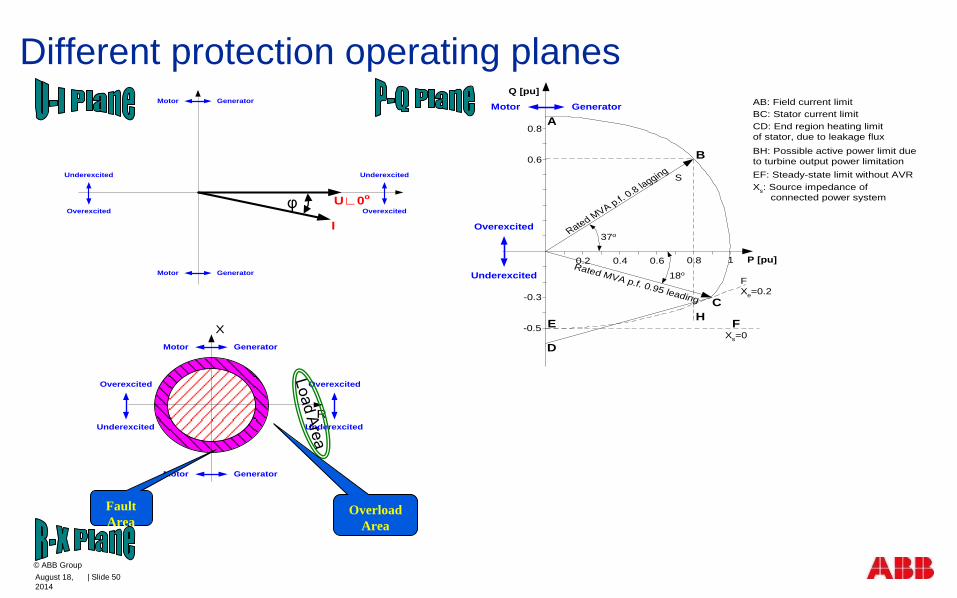
Different protection operating planes
I
U∟0o
GeneratorMotor
GeneratorMotor
Underexcited
Overexcited
Underexcited
Overexcitedφ
0.2 0.4 0.6
-0.3
0.6
-0.5
0.8
Q [pu]
0.8 1
E
D
Xs=0
B
A
Rated MVA p.f.
0.8 lagging
Rated MVA p.f. 0.95 leading
S
37o
F
Xe=0.2
C
H
AB: Field current limit
BC: Stator current limit
CD: End region heating limit
of stator, due to leakage flux
EF: Steady-state limit without AVR
Xs: Source impedance of
connected power system
18o
BH: Possible active power limit due
to turbine output power limitation
GeneratorMotor
Overexcited
Underexcited
F
P [pu]
GeneratorMotor
GeneratorMotor
Overexcited
Underexcited
R
X
Overexcited
Underexcited
Overload
Area
Fault
Area
August 18,
2014
| Slide 50
© ABB Group

Causes
open field circuit
field short circuit
accidental tripping of the field breaker
AVR failure
loss of field at the main exciter
Consequence
Asynchronous running of a synchronous machine without excitation – induction generator
Start drawing reactive power - voltage collapse
Stator end-core heating
Induced rotor currents
MW
MW
MVARS
MVARS
G
G
normal
abnormal
Loss of/under excitation 40
August 18,
2014
| Slide 51
© ABB Group
0.2 0.4 0.6
-0.3
0.6
-0.5
0.8
Q [pu]
0.8 1
E
D
Xs=0
B
A
Rated MVA p.f.
0.8 lagging
Rated MVA p.f. 0.95 leading
S
37o
F
Xe=0.2
C
H
AB: Field current limit
BC: Stator current limit
CD: End region heating limit
of stator, due to leakage flux
EF: Steady-state limit without AVR
Xs: Source impedance of
connected power system
18o
BH: Possible active power limit due
to turbine output power limitation
GeneratorMotor
Overexcited
Underexcited
F
P [pu]

Generator apparent power S during loss of excitation
0.4 sec.
1.2 sec.
2.
43.2
4.0
4.07
4.35
4.41
4.15
4.324.5
0.6
0.3
- 0.3
0.3
0.3
1.0
4.284.18
Q
(p.u.)
P (p.u.)
Loss of/under excitation 40
August 18,
2014
| Slide 52
© ABB Group

Loss of/under excitation 40 Loss of/under excitation is based on under-impedance
measurement (offset Mho)
Main features:
Two zones Z1 and Z2, with independent block and trip
Directional element for additional zone restriction (eg.
under-exiting operation)
R
X
Underexcitation Protection
Restrain area
Z1, Fast zone
Z2, Slow zone
August 18,
2014
| Slide 53
© ABB Group

Loss of Excitation Protection
Xd’/ 2
1.1 Xd

GU
U
STEF PHIZ
59THD U3d/N
TR PTTR
49 Ith
SA PTUF
81 f<
EF4 PTOC
50N/51N IN>
REF PDIF
87N IdN/I
T3W PDIF
87O 3Id/I
REG 670*1.2
ROV2 PTOV
59N 3Uo>
NS2 PTOC
46 I2>
TR PTTR
49 Ith
SDD RFUF
60FL
ZMH PDIS
21 Z<
LEX PDIS
40 Φ<
GUP PDUP
37 P<
GOP PDOP
32 Pß
PSP PPAM
78 Ucos
SA PTOF
81 f>
OEX PVPH
24 U/f>
UV2 PTUV
27 3U<
OV2 PTOV
59 3U>
OC4 PTOC
50/51 3I>
OC4 PTOC
50/51 3I>
CC RBRF
50BF 3I> BF
GEN PDIF
87G 3Id/I
ROV2 PTOV
59N UN>
CC RBRF
50BF 3I> BF
OC4 PTOC
51/67 3I->
AEG GAPC
50AE U/I>
CV MMXU
Meter.
+ REX060, REX061
STTI PHIZ
64S RSE<
ROTI PHIZ
64R RRE<
+ REX060
CV MMXU
Meter.
YY
<
Y
D
YY
<
Uni
t Tra
fo
VTMain Protection Function
Reserve Protection Function
Loss of/Under excitation 40
Endangering condition
Stator reactive current
component
Protected object
Rotor and stator winding
Consequences
Thermal damage of rotor and
stator end regions
Asynchronous machine
operation
Voltage and current variations
August 18,
2014
| Slide 55
© ABB Group

Generator shall produce active power
(i.e. P>0)
When it starts to receive the active
power it acts as a motor (i.e. P<0)
Not dangerous operating condition for
machine but it may be dangerous for the
turbine
Generator motoring protection 32/37
August 18,
2014
| Slide 56
© ABB Group

Causes
loss of prime-mover
low water flow (hydro)
load variations / problems
Effects
steam units overheating of turbine and turbine blades
hydro units cavitation of the blades
Demands
accurate active power measurement (i.e. P~0 & Q=30-60%)
Generator motoring protection 32/37
August 18,
2014
| Slide 57
© ABB Group

OperateLine
Margin
Q
P
Operating point
without turbine torque
Reverse power protection
Set desired pickup (0,5 to 3%)
Set time delay 5-30 s
Sequential tripping logic
August 18,
2014
| Slide 58
© ABB Group

Operate
Line
Margin
Operating point
without turbine torque
Q
P
Low forward power protection
Set desired pickup (1 to 10%)
Set time delay 5-30 s
Sequential tripping logic
Blocked by external signal
when generator is not
loaded
August 18,
2014
| Slide 59
© ABB Group
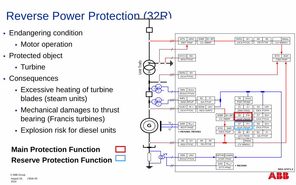
Reverse Power Protection (32R)
Main Protection Function
Reserve Protection Function
Endangering condition
Motor operation
Protected object
Turbine
Consequences
Excessive heating of turbine
blades (steam units)
Mechanical damages to thrust
bearing (Francis turbines)
Explosion risk for diesel units G
U
U
STEF PHIZ
59THD U3d/N
TR PTTR
49 Ith
SA PTUF
81 f<
EF4 PTOC
50N/51N IN>
REF PDIF
87N IdN/I
T3W PDIF
87O 3Id/I
REG 670*1.2
ROV2 PTOV
59N 3Uo>
NS2 PTOC
46 I2>
TR PTTR
49 Ith
SDD RFUF
60FL
ZMH PDIS
21 Z<
LEX PDIS
40 Φ<
GUP PDUP
37 P<
GOP PDOP
32 Pß
PSP PPAM
78 Ucos
SA PTOF
81 f>
OEX PVPH
24 U/f>
UV2 PTUV
27 3U<
OV2 PTOV
59 3U>
OC4 PTOC
50/51 3I>
OC4 PTOC
50/51 3I>
CC RBRF
50BF 3I> BF
GEN PDIF
87G 3Id/I
ROV2 PTOV
59N UN>
CC RBRF
50BF 3I> BF
OC4 PTOC
51/67 3I->
AEG GAPC
50AE U/I>
CV MMXU
Meter.
+ REX060, REX061
STTI PHIZ
64S RSE<
ROTI PHIZ
64R RRE<
+ REX060
CV MMXU
Meter.
YY
<
Y
D
YY
<
Uni
t Tra
fo
VT
August 18,
2014
| Slide 60
© ABB Group

Negative sequence overcurrent (46)
From asymmetric currents, a negative sequence current
component I2, is filtered out.
Negative sequence stator currents rotate in a opposite
direction from the rotor and consequently induce a
120Hz current component into the rotor. As a
consequence rotor ends can over-heat.
IS+IT+
IR+
IT-
IS-
IR-
I22 x t = k
I- , I
46
nsc
August 18,
2014
| Slide 61
© ABB Group

Causes
unbalanced loads
untransposed transmission circuits
unbalanced system faults
series faults
CB pole discrepancy
open circuits
Features
Characteristic adjustable to I22 t=k
Negative phase sequence (46)
August 18,
2014
| Slide 62
© ABB Group

Broken stator winding
GU
U
STEF PHIZ
59THD U3d/N
TR PTTR
49 Ith
SA PTUF
81 f<
EF4 PTOC
50N/51N IN>
REF PDIF
87N IdN/I
T3W PDIF
87O 3Id/I
REG 670*1.2
ROV2 PTOV
59N 3Uo>
NS2 PTOC
46 I2>
TR PTTR
49 Ith
SDD RFUF
60FL
ZMH PDIS
21 Z<
LEX PDIS
40 Φ<
GUP PDUP
37 P<
GOP PDOP
32 Pß
PSP PPAM
78 Ucos
SA PTOF
81 f>
OEX PVPH
24 U/f>
UV2 PTUV
27 3U<
OV2 PTOV
59 3U>
OC4 PTOC
50/51 3I>
OC4 PTOC
50/51 3I>
CC RBRF
50BF 3I> BF
GEN PDIF
87G 3Id/I
ROV2 PTOV
59N UN>
CC RBRF
50BF 3I> BF
OC4 PTOC
51/67 3I->
AEG GAPC
50AE U/I>
CV MMXU
Meter.
+ REX060, REX061
STTI PHIZ
64S RSE<
ROTI PHIZ
64R RRE<
+ REX060
CV MMXU
Meter.
YY
<
Y
D
YY
<
Uni
t Tra
fo
VT
Main Protection Function
Reserve Protection Function
Endangering condition
Unsymmetrical currents
Protected object
Stator windings
Rotor
Consequences
Rotor overheating
Vibrations
August 18,
2014
| Slide 63
© ABB Group

Pole slip / out of step protection (78)
Asynchronous running of a synchronous machine with the rest of the system but with excitation intact (opposed to loss of Field)
Characterized by power (P & Q) oscillation
Manifests as impedance movement in R & X plane
Big mechanical impact on turbine and shaft
Pole Slip typically caused by:
Long fault clearance time (especially close by 3Ph faults are critical)
Inadvertent tripping of a transmission line
(increase of transmission impedance
between generator and load)
Loss of large generator unit
August 18,
2014
| Slide 64
© ABB Group

Pole slip / out of step protection (78)
August 18,
2014
| Slide 65
© ABB Group

Pole slip / out of step protection (78)
GU
U
STEF PHIZ
59THD U3d/N
TR PTTR
49 Ith
SA PTUF
81 f<
EF4 PTOC
50N/51N IN>
REF PDIF
87N IdN/I
T3W PDIF
87O 3Id/I
REG 670*1.2
ROV2 PTOV
59N 3Uo>
NS2 PTOC
46 I2>
TR PTTR
49 Ith
SDD RFUF
60FL
ZMH PDIS
21 Z<
LEX PDIS
40 Φ<
GUP PDUP
37 P<
GOP PDOP
32 Pß
PSP PPAM
78 Ucos
SA PTOF
81 f>
OEX PVPH
24 U/f>
UV2 PTUV
27 3U<
OV2 PTOV
59 3U>
OC4 PTOC
50/51 3I>
OC4 PTOC
50/51 3I>
CC RBRF
50BF 3I> BF
GEN PDIF
87G 3Id/I
ROV2 PTOV
59N UN>
CC RBRF
50BF 3I> BF
OC4 PTOC
51/67 3I->
AEG GAPC
50AE U/I>
CV MMXU
Meter.
+ REX060, REX061
STTI PHIZ
64S RSE<
ROTI PHIZ
64R RRE<
+ REX060
CV MMXU
Meter.
YY
<
Y
D
YY
<
Uni
t Tra
fo
VTMain Protection Function
Reserve Protection Function
Endangering condition
High stator current
Possible system blackout
Protected object
Rotor shaft and stator winding
Consequences
Mechanical damages to shaft
Asynchronous machine
operation (with field intact)
Voltage and current variations
August 18,
2014
| Slide 66
© ABB Group

Frequency protection (81U/O)
Over-frequency 81O: protects in
case of turbine over-speed
Under-frequency 81U:
protection of the steam turbine at the
"critical speed"
August 18,
2014
| Slide 67
© ABB Group

Low network frequency (81U)
GU
U
STEF PHIZ
59THD U3d/N
TR PTTR
49 Ith
SA PTUF
81 f<
EF4 PTOC
50N/51N IN>
REF PDIF
87N IdN/I
T3W PDIF
87O 3Id/I
REG 670*1.2
ROV2 PTOV
59N 3Uo>
NS2 PTOC
46 I2>
TR PTTR
49 Ith
SDD RFUF
60FL
ZMH PDIS
21 Z<
LEX PDIS
40 Φ<
GUP PDUP
37 P<
GOP PDOP
32 Pß
PSP PPAM
78 Ucos
SA PTOF
81 f>
OEX PVPH
24 U/f>
UV2 PTUV
27 3U<
OV2 PTOV
59 3U>
OC4 PTOC
50/51 3I>
OC4 PTOC
50/51 3I>
CC RBRF
50BF 3I> BF
GEN PDIF
87G 3Id/I
ROV2 PTOV
59N UN>
CC RBRF
50BF 3I> BF
OC4 PTOC
51/67 3I->
AEG GAPC
50AE U/I>
CV MMXU
Meter.
+ REX060, REX061
STTI PHIZ
64S RSE<
ROTI PHIZ
64R RRE<
+ REX060
CV MMXU
Meter.
YY
<
Y
D
YY
<
Uni
t Tra
fo
VTMain Protection Function
Reserve Protection Function
Endangering condition
Under-frequency
Protected object
Transformer
Steam turbine
Consequences
Over-excitation
Steam turbine vibrations
August 18,
2014
| Slide 68
© ABB Group

High Network Frequency (81O)
GU
U
STEF PHIZ
59THD U3d/N
TR PTTR
49 Ith
SA PTUF
81 f<
EF4 PTOC
50N/51N IN>
REF PDIF
87N IdN/I
T3W PDIF
87O 3Id/I
REG 670*1.2
ROV2 PTOV
59N 3Uo>
NS2 PTOC
46 I2>
TR PTTR
49 Ith
SDD RFUF
60FL
ZMH PDIS
21 Z<
LEX PDIS
40 Φ<
GUP PDUP
37 P<
GOP PDOP
32 Pß
PSP PPAM
78 Ucos
SA PTOF
81 f>
OEX PVPH
24 U/f>
UV2 PTUV
27 3U<
OV2 PTOV
59 3U>
OC4 PTOC
50/51 3I>
OC4 PTOC
50/51 3I>
CC RBRF
50BF 3I> BF
GEN PDIF
87G 3Id/I
ROV2 PTOV
59N UN>
CC RBRF
50BF 3I> BF
OC4 PTOC
51/67 3I->
AEG GAPC
50AE U/I>
CV MMXU
Meter.
+ REX060, REX061
STTI PHIZ
64S RSE<
ROTI PHIZ
64R RRE<
+ REX060
CV MMXU
Meter.
YY
<
Y
D
YY
<
Uni
t Tra
fo
VT
Main Protection Function
Reserve Protection Function
Endangering condition
Over-frequency
Protected object
Turbine
Rotor
Consequences
Mechanical stresses
Turbine vibrations
August 18,
2014
| Slide 69
© ABB Group

3U>
AVR
Uinj
With faulty AVR overvoltage can cause over excitation of the generator-transformer block
V can sharply increase after load rejection followed by machine runaway
Over-voltage protection, 59
August 18,
2014
| Slide 70
© ABB Group

Over-voltage protection (59)
Main Protection Function
Reserve Protection Function
Endangering condition
Over-voltage
Improper voltage regulation
Protected object
Electrical circuits
Consequences
Increased risk for earth-faults
Over-excitation G
U
U
STEF PHIZ
59THD U3d/N
TR PTTR
49 Ith
SA PTUF
81 f<
EF4 PTOC
50N/51N IN>
REF PDIF
87N IdN/I
T3W PDIF
87O 3Id/I
REG 670*1.2
ROV2 PTOV
59N 3Uo>
NS2 PTOC
46 I2>
TR PTTR
49 Ith
SDD RFUF
60FL
ZMH PDIS
21 Z<
LEX PDIS
40 Φ<
GUP PDUP
37 P<
GOP PDOP
32 Pß
PSP PPAM
78 Ucos
SA PTOF
81 f>
OEX PVPH
24 U/f>
UV2 PTUV
27 3U<
OV2 PTOV
59 3U>
OC4 PTOC
50/51 3I>
OC4 PTOC
50/51 3I>
CC RBRF
50BF 3I> BF
GEN PDIF
87G 3Id/I
ROV2 PTOV
59N UN>
CC RBRF
50BF 3I> BF
OC4 PTOC
51/67 3I->
AEG GAPC
50AE U/I>
CV MMXU
Meter.
+ REX060, REX061
STTI PHIZ
64S RSE<
ROTI PHIZ
64R RRE<
+ REX060
CV MMXU
Meter.
YY
<
Y
D
YY
<
Uni
t Tra
fo
VT
August 18,
2014
| Slide 71
© ABB Group

Overfluxing protects generator and
transformer magnetic core against
overheating
Specially critical during start-up and
shut-down
Wide frequency operation of the
relay important for generator
protection
E UorB const const
f f
Over-fluxing (excessive V/Hz), 24
August 18,
2014
| Slide 72
© ABB Group

Incorrect turbine control (24, 81O/U)
Main Protection Function
Reserve Protection Function
GU
U
STEF PHIZ
59THD U3d/N
TR PTTR
49 Ith
SA PTUF
81 f<
EF4 PTOC
50N/51N IN>
REF PDIF
87N IdN/I
T3W PDIF
87O 3Id/I
REG 670*1.2
ROV2 PTOV
59N 3Uo>
NS2 PTOC
46 I2>
TR PTTR
49 Ith
SDD RFUF
60FL
ZMH PDIS
21 Z<
LEX PDIS
40 Φ<
GUP PDUP
37 P<
GOP PDOP
32 Pß
PSP PPAM
78 Ucos
SA PTOF
81 f>
OEX PVPH
24 U/f>
UV2 PTUV
27 3U<
OV2 PTOV
59 3U>
OC4 PTOC
50/51 3I>
OC4 PTOC
50/51 3I>
CC RBRF
50BF 3I> BF
GEN PDIF
87G 3Id/I
ROV2 PTOV
59N UN>
CC RBRF
50BF 3I> BF
OC4 PTOC
51/67 3I->
AEG GAPC
50AE U/I>
CV MMXU
Meter.
+ REX060, REX061
STTI PHIZ
64S RSE<
ROTI PHIZ
64R RRE<
+ REX060
CV MMXU
Meter.
YY
<
Y
D
YY
<
Uni
t Tra
fo
VT
Endangering condition
Under-frequency
Protected object
Transformer
Consequences
Over-excitation
August 18,
2014
| Slide 73
© ABB Group

Operates when generator is
energized while offline
Behaved a induction motor
Significant damages to rotor
Operating errors, CB flash-over
voltage controlled OC most
commonly used
Accidental energizing, 50AE
August 18,
2014
| Slide 74
© ABB Group

Accidental energizing (50AE)
* 3Z< is a delayed reserve protection
GU
U
STEF PHIZ
59THD U3d/N
TR PTTR
49 Ith
SA PTUF
81 f<
EF4 PTOC
50N/51N IN>
REF PDIF
87N IdN/I
T3W PDIF
87O 3Id/I
REG 670*1.2
ROV2 PTOV
59N 3Uo>
NS2 PTOC
46 I2>
TR PTTR
49 Ith
SDD RFUF
60FL
ZMH PDIS
21 Z<
LEX PDIS
40 Φ<
GUP PDUP
37 P<
GOP PDOP
32 Pß
PSP PPAM
78 Ucos
SA PTOF
81 f>
OEX PVPH
24 U/f>
UV2 PTUV
27 3U<
OV2 PTOV
59 3U>
OC4 PTOC
50/51 3I>
OC4 PTOC
50/51 3I>
CC RBRF
50BF 3I> BF
GEN PDIF
87G 3Id/I
ROV2 PTOV
59N UN>
CC RBRF
50BF 3I> BF
OC4 PTOC
51/67 3I->
AEG GAPC
50AE U/I>
CV MMXU
Meter.
+ REX060, REX061
STTI PHIZ
64S RSE<
ROTI PHIZ
64R RRE<
+ REX060
CV MMXU
Meter.
YY
<
Y
D
YY
<
Uni
t Tra
fo
VT
Main Protection Function
Reserve Protection Function
*
Endangering condition
Stator overcurrent or
unsymmetrical currents
Protected object
Bearings
Rotor
Consequences
Bearing damages due to low
oil pressure
Rotor overheating
Stator overheating
August 18,
2014
| Slide 75
© ABB Group

Breaker-failure protection (50BF)
Issues a back-up trip of adjacent breaker in case of failure of the circuit
breaker of the protected object to open (i.e. to interrupt the primary
circuit)
Its operation in most cases trips only local breakers
Commonly uses the bus bar protection disconnector replica logic to
route its tripping command to adjacent breakers
Re-trip (t1), Backup trip / bus-strip (t2), Second back-up trip timer
(t3)
Short reset time (15ms)
Known CB faulty (bypass t2)
Operating mode
Current / Contact / Current & Contact
August 18,
2014
| Slide 76
© ABB Group

Breaker fails to open the circuit (50BF)
GU
U
STEF PHIZ
59THD U3d/N
TR PTTR
49 Ith
SA PTUF
81 f<
EF4 PTOC
50N/51N IN>
REF PDIF
87N IdN/I
T3W PDIF
87O 3Id/I
REG 670*1.2
ROV2 PTOV
59N 3Uo>
NS2 PTOC
46 I2>
TR PTTR
49 Ith
SDD RFUF
60FL
ZMH PDIS
21 Z<
LEX PDIS
40 Φ<
GUP PDUP
37 P<
GOP PDOP
32 Pß
PSP PPAM
78 Ucos
SA PTOF
81 f>
OEX PVPH
24 U/f>
UV2 PTUV
27 3U<
OV2 PTOV
59 3U>
OC4 PTOC
50/51 3I>
OC4 PTOC
50/51 3I>
CC RBRF
50BF 3I> BF
GEN PDIF
87G 3Id/I
ROV2 PTOV
59N UN>
CC RBRF
50BF 3I> BF
OC4 PTOC
51/67 3I->
AEG GAPC
50AE U/I>
CV MMXU
Meter.
+ REX060, REX061
STTI PHIZ
64S RSE<
ROTI PHIZ
64R RRE<
+ REX060
CV MMXU
Meter.
YY
<
Y
D
YY
<
Uni
t Tra
fo
VT
Main Protection Function
Reserve Protection Function
Endangering condition
Stator overcurrent or
unsymmetrical currents
Protected object
Electrical circuits
Rotor
Consequences
Rotor overheating
Stator overheating
Prolonged damages caused by
the fault current
August 18,
2014
| Slide 77
© ABB Group

Conclusion
Stator earth faults
Rotor earth faults
Stator short circuits
Stator/rotor interturn faults
External faults
Abnormal operation
August 18,
2014
| Slide 78
© ABB Group
Thank you for your participation
Shortly, you will receive a link to an archive of this presentation.
To view a schedule of remaining webinars in this series, or for more
information on ABB’s protection and control solutions, visit:
www.abb.com/relion
August 18,
2014
| Slide 79
© ABB Group

•Relion Series Relays – Advanced flexible platform for protection and control
•RTU 500 Series – Proven, powerful and open architecture
•MicroSCADA - Advanced control and applications
•Tropos – Secure, robust, high speed wireless solutions
This webinar brought to you by:ABB Power Systems Automation and Communication
We combine innovative, flexible and open products with
engineering and project services to help our
customers address their challenges.

August 18,
2014
| Slide 81
© ABB Group