Embed Size (px)
Citation preview

THESIS FOR THE DEGREE OF LICENTIATE OF ENGINEERING
Recycling of selenium from CIGS solar cell
materials
ANNA M. K. GUSTAFSSON
Industrial Materials Recycling
Department of Chemical and Biological Engineering
CHALMERS UNIVERSITY OF TECHNOLOGY
Gothenburg, Sweden 2012

Recycling of selenium from CIGS solar cell materials
ANNA M. K. GUSTAFSSON
© ANNA M. K. GUSTAFSSON, 2012.
Technical report no 2012:11
Industrial Materials Recycling
Department of Chemical and Biological Engineering
Chalmers University of Technology
SE-412 96 Gothenburg
Sweden
Telephone + 46 (0)31-772 1000
Cover: Suggested recycling process for selenium from CIGS solar cell materials
Chalmers Reproservice
Gothenburg, Sweden 2012

Recycling of selenium from CIGS solar cell materials
ANNA M. K. GUSTAFSSON
Industrial materials recycling
Department of Chemical and Biological Engineering
Chalmers University of Technology
ABSTRACT
Today the importance of solar cells as a power source is growing due to the environmental
advantages compared to fossil fuels. One of the most promising new solar cell materials,
resulting in high efficiency solar cells, is copper indium gallium selenide (CIGS). CIGS is
used in thin film solar cells, which require less semiconductor material than conventional
silicon solar cells and as a result are much more cost effective. Lately the issue of recycling
material from spent solar cells and taking care of production waste has received increasing
attention, especially since solar cell technologies utilize expensive, rare, or toxic elements.
The production of solar cells requires high purity materials, putting high demands on the
recycling processes if the recycled material is to be used directly in new solar cells. One way
to obtain high purity materials is to separate the element of interest in the gas phase while
other elements remain in the liquid or solid state. To facilitate the separation more volatile
compounds of the element can be formed through chemical reactions. As the first step in the
development of a recycling process for CIGS materials this study aimed to use such a method
for separation of selenium from CIGS.
The feasibility to recycle selenium from CIGS through separation of selenium as
either hydrogen selenide or selenium oxide was examined. Several different methods for
separation of selenium as hydrogen selenide (H2Se) were tested, but none of them was
successful. However, separation of selenium via oxidation of CIGS at elevated temperatures
proved to be feasible. The oxidation resulted in the formation of selenium dioxide (SeO2),
which after cooling of the gas could be collected as crystals. After oxidation at 1000°C only a
few percent by weight of the selenium remained in the CIGS material. To recover the
selenium the selenium dioxide was reduced. Two different reduction methods were tested.
First the selenium dioxide was reduced by an organic compound, in a so called Riley
reaction. Next sulphur dioxide gas was used as a reducing agent. Both methods resulted in
high yield and high purity of the recycled selenium. Thus, the aim of the study was achieved
and the method will be further developed in the future. The next step in the development of a
recycling process for CIGS materials will be the separation of the remaining elements.
KEYWORDS: Recycling, Solar cells, Photovoltaic, Thin film, CIGS

LIST OF PUBLICATIONS
This thesis is based on the work presented in:
Paper I
Gustafsson A., Foreman M., Ekberg C. A feasibility study of recycling of high purity
selenium from CIGS solar cell materials.
Submitted to Progress in Photovoltaics: Research and Applications (2012-03-29)
Contribution report
Paper I All experimental work, data treatment, evaluation and major part of writing of the
manuscript.

Table of Contents
1. Introduction ........................................................................................................................... 3
1.1 Objective ........................................................................................................................... 4
2. Background ........................................................................................................................... 5
2.1 Solar cells .......................................................................................................................... 5
2.2 CIGS solar cells ................................................................................................................. 7
2.3 Recycling of solar cells ..................................................................................................... 7
3. Theory .................................................................................................................................. 11
3.1 Dissolution of CIGS in acids ........................................................................................... 11
3.2 Separation of selenium from CIGS ................................................................................. 11
3.2.1 Reduction of selenium to hydrogen selenide ............................................................ 11
3.3.2 Pyrometallurgical processing – Distillation of selenium dioxide ............................ 12
3.4 Selenium .......................................................................................................................... 13
4. Materials and methods ....................................................................................................... 15
4.1 Materials .......................................................................................................................... 15
4.2 Methods ........................................................................................................................... 16
4.2.1 ICP-OES ................................................................................................................... 16
4.2.2 ICP-MS ..................................................................................................................... 16
4.2.3 Gas-MS ..................................................................................................................... 16
4.2.4 GC-MS ...................................................................................................................... 16
4.2.6 XRD .......................................................................................................................... 17
5. Experimental ....................................................................................................................... 19
5.1 Dissolution of CIGS ........................................................................................................ 19
5.1.1 Oxidizing acid ........................................................................................................... 19
5.1.2 Non-oxidizing acid .................................................................................................... 19
5.2 Reduction of CIGS - hydrogen selenide ......................................................................... 20
5.2.1 Reduction of CIGS with hydrogen gas ..................................................................... 20
5.2.2 Reduction of CIGS with sodium borohydride (NaBH4) ............................................ 21
5.2.3 Reduction of CIGS with ammonia and hydrogen peroxide ...................................... 22
5.3 Distillation of selenium dioxide ...................................................................................... 22
5.3.1 Oxidation experiment ............................................................................................... 22
5.3.2. Reduction of selenium dioxide – Riley reaction (Oxidation of deoxybenzoin to
benzil) ................................................................................................................................ 23
5.3.3 Reduction of selenium dioxide – Sulphur dioxide .................................................... 24
6. Results and discussion ........................................................................................................ 25
6.1 Dissolution of CIGS ........................................................................................................ 25
6.1.1 Oxidizing acid ........................................................................................................... 25
6.1.2 Non-oxidizing acids .................................................................................................. 26
6.2 Reduction of CIGS - hydrogen selenide ......................................................................... 26
6.2.1 Reduction of CIGS with hydrogen gas ..................................................................... 26

2
6.2.2 Reduction of CIGS with sodium borohydride ........................................................... 27
6.2.3 Reduction of CIGS with ammonia and hydrogen peroxide ...................................... 27
6.3 Distillation of selenium dioxide ...................................................................................... 27
6.3.1 Oxidation experiment ............................................................................................... 27
6.3.2. Reduction of selenium dioxide – Riley reaction (Oxidation of deoxybenzoin to
benzil) ................................................................................................................................ 29
6.3.3 Reduction of selenium dioxide – Sulphur dioxide .................................................... 30
6.3.4 Purity of the recycled selenium ................................................................................ 31
7. Conclusions and process suggestions ................................................................................ 33
7.1 Conclusions ..................................................................................................................... 33
7.2 Process suggestions ......................................................................................................... 34
8. Future work ......................................................................................................................... 35
Acknowledgements ................................................................................................................. 37
References ................................................................................................................................ 39
List of Abbreviations and Terms ........................................................................................... 43

3
1. Introduction
Solar cells are considered by many to be part of the future energy mix [1]. The amount of
energy coming from the sun makes it the largest available energy source, but the question is
how to best utilize that energy [2]. One way to exploit solar energy is to use solar cells, which
transform solar energy into electricity. The ability of some materials to convert light into
electricity is called the photovoltaic (PV) effect and was discovered by Henry Becquerel in
1839 [3]. Since then extensive work has resulted in a number of different types of solar cells
which are used in a variety of applications; from terrestrial applications supplying power to
the national grid to applications in space [4]. Today the importance of solar cells as a power
source is growing due to the environmental advantages compared to fossil fuels [5]. New PV
materials, devices and production methods are constantly being developed in order to
increase cell efficiency and minimize the energy and material consumption, thereby making
PV power more competitive both economically and environmentally compared with other
power sources. The progress in this area has been reviewed by several authors [5-11]. At
present the most common solar cell material is silicone, but other types of PV materials, such
as cadmium telluride (CdTe) and copper indium gallium selenide (CIGS), are making
advances on the global market [12]. CdTe and CIGS are used in thin film solar cells, which
require much less semiconductor material than conventional silicon solar cells and as a result
are much more cost effective [13]. Lately the issue of recycling spent solar cells and
production waste has been receiving attention, especially since most PV technologies utilize
expensive, rare, or toxic elements [14]. This is definitely the case with CIGS thin film solar
cells where the utilization of the rare and valuable metals indium and gallium makes
recycling of CIGS materials necessary in order to keep production costs down [15]. In 2010
the European Commission identified both indium and gallium, along with only twelve other
materials, as critical raw materials with regards to supply shortage and economic impact in
the European Union [16]. The production of solar cells requires the input materials for
semiconductor production to be of extremely high purity. This means that recycled materials
must have a purity of 99.999% (5N) to be used directly in solar cell production [17]. To
today’s date, none of the recycling processes developed for CIGS (or CdTe) are generating
materials with such purity.

4
1.1 Objective
The objective of this PhD project is to develop a recycling process for CIGS materials. The
process should result in the separated elements having a purity of at least 5N with respect to
the elements chromium, manganese, iron, nickel and zinc. These are the critical elements that
decrease the efficiency of solar cells. The process should be economically feasible and
scalable to an industrial scale. The goal is also to implement the developed process in a pilot
scale at the CIGS solar cell manufacturer Midsummer AB [18]. At present the main intention
is to recycle waste material from the production process, but in the future the process should
also be applicable to recycling of discarded solar cells from manufacturing and spent solar
cells from energy production. The work presented in this thesis is focused on the separation
of selenium from the other elements in the CIGS material. Even though selenium is the least
expensive of the elements in CIGS it constitutes half of the material and therefore contributes
significantly to the cost of the material. Future work will be concentrated on the separation of
the other elements in the material.

5
2. Background
2.1 Solar cells
The active material in a solar cell is a semiconductor. When sunlight hits the semiconductor
material the absorbed energy promotes an electron to the conduction band making the
material conductive [19]. The construction of the device then ensures that the free electron
can only be transported in one direction, thereby generating an electric current in an outer
circuit connected to the device. The standard type of solar cell is the pn-junction solar cell
[4], see Figure 2.1.
Back contact
p-type
n-type
+ + + + + + + + + + + + + + +_ _ _ _ _ _ _ _ _ _ _ _ _ _ _ Depletion region
+
_
Front contacts
Figure 2.1. Schematic cross-section of standard pn-junction solar cell [19].
A semiconductor material that is deficient in electrons is called p-type (p for positive). One
example of such a material is silicon doped with an element with fewer valence electrons, e.g.
boron. Doping is the deliberate introduction of an impurity into a material. If, on the other
hand, the material is in excess of valence electrons it is called n-type (n for negative). Doping
of silicon with e.g. phosphorus, gives this kind of material. When regions of n-type and p-
type doping meet in a semiconductor crystal electrons from the n-type will migrate into the p-
type in order to balance the difference in electron concentration [19]. The migration of
electrons into the p-type will give rise to a depletion region and a negative charge that
counteracts further migration will be established. The electric field in the depletion region
ensures that electrons can only be transported in one direction, from p-type to n-type [20]. If
the same semiconductor is used as both p-type and n-type, as in the example with silicon

6
above, the junction is called a homojunction. When different materials are used, e.g.
CIGS/CdS, the junction is called a hetrojunction [20].
In addition to the semiconductor, a solar cell consists of several different layers. The
thickness of the absorber layer in thin film solar cells is typically <2 µm [21] which means
that it is more than a 100 times thinner than silicon wafers [6]. Thus, while mono- and
multicrystalline wafers are self-supporting (see Figure 2.1) thin film solar cells, e.g.
amorphous silicon, CdTe and CIGS, need a supporting base called a substrate, see Figure 2.2
[22].
Glass substrate
Mo back contakt
CIGS absorber layer
(p-type)
CdS window layer (n-type)
TCO Glass substrate
Mo back contakt
CdTe absorber layer
(p-type)
CdS window layer (n-type)
TCO
(a) (b)
Light LightContact grid
Figure 2.2. Schematic cross-section of (a) CIGS solar cell and (b) CdTe solar cell [22].
For the solar cell to produce electricity it must be connected to an outer circuit. This is
facilitated by contacts at the front and back of the semiconductor material. The back contact
is usually a thin layer of molybdenum. The front contact can be provided by screen printing
of a metal grid (Figure 2.1), alternatively a transparent conductive oxide (TCO) can be used,
e.g. zinc oxide (Figure 2.2b) or a combination of the two (Figure 2.2a) [14]. For energy
production several solar cells are connected to form a solar cell module. Normally the module
is laminated with EVA (ethylene-vinyl acetate) polymer on to a glass plate and encased in an
aluminium frame for protection [23].
The top efficiency for different types of solar cells and solar cell modules are
reviewed annually [24]. Currently the record holder for a small single junction laboratory
devise (area of 1 cm2) is a gallium arsenide cell with an efficiency of 28.3%. This can be
compared with 25.0% for crystalline silicone, 19.6% for CIGS and 16.7% for CdTe. The
corresponding numbers for solar cell modules are 22.9% for crystalline silicone, 15.7% for

7
CIGS and 12.8% for CdTe. The lower efficiency of the modules is due to the difficulty in
scaling up the production methods. Modules made on an industrial scale seldom reach
efficiencies over 10% for thin film technologies and 16% for silicon wafer technology due to
the balance between efficiency and cost [13].
2.2 CIGS solar cells
In CIGS solar cells the semiconductor layer is made from Cu(In,Ga)Se2. This is a material
consisting of CuInSe2 with some percentages of the indium replaced by gallium. By
modifying the amount of gallium the bandwidth (see section 2.1) of the solar cell can be
adjusted and a higher efficiency device can be achieved [21, 25].
The possibility to modify the composition of the CIGS absorber and produce high
efficiency devices at laboratory scale has made the technology one of the most promising thin
film technologies [6, 24]. The challenge with this technology is that the CIGS material
contains four different elements which make the system complex and production therefore
demands a high level of process control [25]. The scale up to large-scale production with
preserved solar cell efficiency has been difficult to achieve due to the complexity of the
processes [6] and high investment costs [13]. There are several different manufacturing
processes for CIGS solar cells, but the two most common approaches are (1) co-evaporation
and (2) selenization [6]. In the co-evaporation process evaporation sources are heated under
vacuum and the evaporated atoms are deposited on the substrate. The selenization process
starts with the deposition of a film containing only copper, indium and gallium, with e.g.
sputtering, followed by selenization with for example hydrogen selenide [26]. The co-
evaporation process has been used to produce high efficiency laboratory scale solar cells, but
the selenization process has been more successful in industrial scale production [14].
The advantage of thin film technologies is that each solar cell only contains minor
amounts of the valuable semiconductor, but there is a problem. Independent of the production
method, large amounts (up to 34%) of the starting material are lost in different waste streams
[27]. The recycling of this waste material is of great importance for the future advance of the
technology.
2.3 Recycling of solar cells
The interest in recycling of solar cell modules has increased during recent years, but normally
only the aluminium frame and the glass encasing the solar cells are taken care of. Only two
recycling processes for solar cells have been commercialized [28]. The first process,
8
developed by Deutsche Solar, is used to treat crystalline silicon solar modules and the second
process, developed by First Solar, is used to treat cadmium telluride solar cells.
The process developed by Deutsche Solar was described by Bombach et al. [29]. The
laminate on the modules was removed in a thermal process followed by manual separation of
the glass. The contacts, anti-reflective coating and pn-junction were removed by etching. No
details of the chemicals used in the etching step were given. After treatment the silicon
wafers were reused in new solar cells. Broken wafers were melted and made into new wafers.
The process used by First Solar to recycle solar cell modules has been described by
Mezei et al [30, 31]. The modules were dismantled and the semiconductor material was
leached from the glass. The leaching was performed using a mixture of sulphuric acid and
hydrogen peroxide and resulted in a 99% leaching of cadmium and tellurium [30]. After
leaching, the metals were precipitated with sodium hydroxide forming stable compounds
making further recycling of tellurium impossible. Due to the difficulties in recycling
tellurium after precipitation, further development of this process was studied [31]. A
combination of solvent extraction and electrowinning was examined as an alternative to the
precipitation step. This process gave promising results at a pilot scale and may be
implemented at full scale in the future.
Other recycling methods for solar cells have been described in the literature, but have
not yet been commercialized. Mono- and multicrystalline silicone are the dominating solar
cell materials on the market with a market share of 81% [12]. During the last 15 years
insufficient feedstock supply and the high price of silicon suitable for solar cell production
[32] has made recycling an important issue. The focus on recycling of mono- and
multicrystalline silicon solar cells has been mostly on the reuse of wafers with [33-36] or
without [37, 38] removal of the pn-junction and other layers. There has also been a lot of
work done on the recycling of the waste material (kerf loss) from wafer production [39-48].
A lot of attention has been given to the recycling of CdTe solar cells, partly due to the
toxicity of cadmium and partly because of the high cost and limited supply of tellurium [27,
49]. Two different approaches to the recycling of CdTe can be distinguished. The first
approach includes removal of the semiconductor from the substrate and a purification step,
but no separation of the elements [17, 50, 51]. In this case the challenge of closing the loop
for the semiconductor material is transferred to the producers of solar cell semiconductor
materials. The second approach includes a variation with a separation step separating the
elements into separate process streams [52-54]. Furthermore, a completely different process,

9
where an electrochemical cell was used to redeposit CdTe from an old solar cell onto a new
substrate, has been developed by Menezes [55].
Recycling of CIGS solar cells and waste material is motivated by the high price of
indium and gallium and several different processes have been developed. In the same way as
with recycling of CdTe, some processes only consider the removal of the semiconductor
material from the substrate followed by purification and reuse in normal solar cell
semiconductor production [17, 56]. In both these cases no details of the purification or reuse
processes were provided. As for CdTe, Menezes has developed an electrochemical method
for transferring CIGS from old solar cells on to new substrates [57]. A cyclic variation of the
electrochemical potential was used to dissolve the old CIGS film and deposit the material on
a new cell. However, no details were given concerning the result of the recycling. A more
detailed study of the mechanisms, e.g. potentials and electrolyte composition, of the process
has also been done [58]. So far only two recycling processes have been developed where the
elements are separated [23, 59]. Drinkard et al. used a combination of hydrometallurgical
methods, including leaching and electrolysis, to separate indium and gallium from copper and
selenium. In the next step a pyrometallurgical method was used to separate selenium from
copper. The SENSE (Sustainability EvaluatioN of Solar Energy systems) project also used
leaching as the means of separating the CIGS material from the substrate. In the next step
separation of indium was done by solvent extraction. Selenium was then reduced with
sulphur dioxide and separated from the solution via filtration. Gallium was precipitated and
separated as gallium hydroxide.

10

11
3. Theory
3.1 Dissolution of CIGS in acids
CIGS can be leached in an oxidizing acid e.g. nitric acid [23, 50, 59], but no records of non-
oxidizing acids e.g. hydrochloric and sulphuric acid have been found. If subsequent reduction
of the dissolved elements is of interest, it is not possible to use oxidizing acids for the
dissolution. However, a combination of a non-oxidizing acid and hydrogen peroxide can be
used [59, 60]. After the dissolution the hydrogen peroxide can be removed from the solution
by decomposition at elevated temperatures.
3.2 Separation of selenium from CIGS
The use of recycled CIGS materials in new solar cells requires separation and purification of
the elements [6, 17]. Selenium is the element in CIGS that is most unlike the other elements
[26]. Thus, the separation of selenium is the best starting point for recycling. There are
several possible hydrometallurgical methods that could be used for the separation e.g. ion
exchange [61] or precipitation from aqueous solution [59], but it would be of advantage if the
separation could be done in such a way that selenium could be obtained directly at high
purity. Separation of selenium, or a compound thereof, in a gas phase is therefore of interest.
3.2.1 Reduction of selenium to hydrogen selenide
Under certain conditions selenium can be reduced to hydrogen selenide which is a gas at
room temperature. The reduction of the selenium to hydrogen selenide could therefore
possibly be used as a method for separation of selenium from the other elements in CIGS. In
addition, hydrogen selenide is used in the selenization step of the CIGS solar cell production
[26]. Thus, the recycled selenium in the form of hydrogen selenide could be used directly in
new solar cells.
The preparation of hydrogen selenide can be done in several different ways. The most
common production methods involve the reaction of water with aluminum selenide (Al2Se3)
or the hydrolysis of iron selenide (FeSe) by a dilute mineral acid [62], but there are also
methods to produce hydrogen selenide directly from selenium, either in solid state or
dissolved in liquid. According to Patnaik hydrogen selenide can be produced via reduction of
selenium with hydrogen gas at 440 °C [26].
Se (s or g) + H2 (g) → H2Se (g) (1)

12
This reaction between selenium and hydrogen in the gas phase has also been described by
Greenwood, but here the reaction is said to be surface catalyzed in the temperature range
between 350 and 650° C with an optimum temperature of 520 °C [62]. No information
concerning the catalyst was found. Sonoda et al. prepared hydrogen selenide from metallic
selenium with water and carbon monoxide gas in the presence of a mild base. The hydrogen
selenide gas formed was liberated from the solution by acidification with sulphuric acid [63].
Se (s) + CO (g) + H2O (l) → H2Se (g) + CO2 (g) (2)
There are some examples of sodium borohydride being used as reducing agent for production
of hydrogen selenide for the analysis of selenium with atomic absorption spectroscopy [60,
64]. Several metals interfere with this reaction, among them copper [64]. To avoid
interference the copper can be removed from the solution as copper hydroxide precipitate
[60]. Also, some electrochemical methods have been suggested [65, 66]. Hydrogen peroxide,
even though it is known for its oxidizing properties, can under certain conditions also work as
a reducing agent [26, 62].
Hydrogen selenide is a flammable and highly toxic gas [62], the production and
handling therefore demands high levels of safety.
3.3.2 Pyrometallurgical processing – Distillation of selenium dioxide
Distillation is a well-tried method for separation of different elements and compounds.
During distillation the difference in volatility of the different compounds is utilized. An
advantage with this kind of separation is that the separated element can be obtained with very
high purity if optimal process parameters are used. An example of an established distillation
process is the Mond process, which is used for purification of nickel [67]. Nickel metal is
reacted with carbon monoxide forming the volatile nickel tetracarbonyl (Ni(CO)4) that can be
separated from other non-volatile carbonyl compounds. After the separation the nickel
tetracarbonyl is decomposed at temperatures above 180 °C and the nickel is recovered [68].
One distillation method that could be used for separation of selenium from CIGS is
oxidation of the selenium to selenium dioxide via heating in an atmosphere containing
oxygen. The oxidation of selenium is a known method for purification of selenium [69]. The
impurities in the selenium form non-volatile oxides and are thereby separated from the
selenium. At temperatures above 317 °C selenium dioxide is a gas that upon cooling sublimes
and can be collected as crystals. Oxidation reaction:
Se (s) + O2 (g) → SeO2 (g) (3)

13
Sublimation:
SeO2 (g) → SeO2 (s) (4)
After reduction the process results in high purity selenium. Reduction of selenium dioxide to
selenium can be achieved by the use of the selenium dioxide as a mild oxidizing agent for
organic compounds, as first described by Riley et al. [70].
(5)
Figure 3.1. Riley reaction oxidation of keton to diketon.
Since then, these types of reaction have been extensively studied and used in numerous
applications [69, 71, 72]. Selenium dioxide can also be reduced using a wide variety of
inorganic reducing agents [69]. One of the reducing agents described in the literature is
sulphur dioxide gas [59, 62, 73, 74].
SeO2 (aq) + SO2 (g) → Se (s) + H2SO4 (aq) (6)
The advantage of this reduction method is the decreased risk of contamination of the
produced selenium.
3.4 Selenium
Selenium is a rare element in the earth’s crust that is recovered as a by-product of copper
extraction [75]. Selenium is found in several allotropic forms [62]. The amorphous form
exists in two different colours, red and black. The red selenium is transformed to black
selenium when heated or with aging. The black selenium is the form most commonly used in
industry. In the crystalline form selenium is found as dark red, transparent crystals and the
metallic form is glossy grey [26]. Upon heating the amorphous and crystalline allotropes are
transformed into metallic selenium [62].
+ SeO2 (l)R1
R2
O
O
R1
R2
O
+ Se (s) + H2O (l)∆

14

15
4. Materials and methods
4.1 Materials
CIGS materials from solar cell production were supplied by Midsummer AB [18]. For all
experiments the CIGS material was crushed in an agate mortar and mixed carefully for
homogeneity. The crushed material was sieved and the preferred particle size was chosen.
For the dissolution experiments a particle size of 180-250 µm was used. For the fluidized bed
batch reactor experiments a particle size of 125-180 µm was used. For the oxidation
experiments the crushed material was only characterized and a mix of different particle sizes
was used, see Table 4.1.
Table 4.1. Particle size distribution of starting material for the oxidation experiments.
Particle size
(mm)
Share of material with the
given particle size (wt%)
> 2.0 8±0.6
0.25-2.0 67±1.2
0.075-0.25 15.5±0.6
< 0.075 9.5±0.5
For the ICP-OES analysis the CIGS material was dissolved in concentrated nitric acid (pro
analysis, 65%, Acros Organics), or in the case of the residues from the oxidation experiment
hot aqua regia. The aqua regia was prepared by mixing nitric acid (pro analysis, 65%, Acros
Organics) and hydrochloric acid (puriss, 37%, Sigma-Aldrich) with a molar ratio of 1:3
respectively. Suprapure nitric acid (65%, Merck) and MilliQ water (>18 MΩ, Millipore Milli-
Q Plus 185) was used to prepare a 0.1 M suprapure nitric acid used to dilute the samples
before characterization. The chemical composition of the starting material was determined
with ICP-OES, see Table 4.2.
Table 4.2. Chemical composition of the CIGS material used for the experiments. The uncertainty
corresponds to one standard deviation.
Cu(wt%) In(wt%) Ga(wt%) Se(wt%)
17.4±0.2 28.3±0.5 5.3±0.1 49.0±0.8
For the purity measurements with ICP-MS the samples were dissolved in suprapure nitric
acid (65%, Merck) and diluted to an acid concentration of 1 M with MilliQ water (>18 MΩ).
The samples analyzed with GC-MS were dissolved and diluted in acetone (pro analysis,
Fischer Scientific) to a concentration of 16 mg/l.

16
4.2 Methods
4.2.1 ICP-OES
Inductively Coupled Plasma – Optical Emission Spectroscopy (ICP-OES) is used to analyze
the concentration of different elements in solution. After passing through a nebulizer the
analytes in the liquid sample are atomized in the plasma. The high excitation energy of the
atoms in the plasma will cause them to emit electromagnetic radiation, which is detected in
the optical emission detector. More information on ICP-OES is given by Dean (2005) [76]. A
Thermo iCAP 6500 was used to analyze the composition of the different solar cell materials,
before and after the experiments.
4.2.2 ICP-MS
Inductively Coupled Plasma – Mass Spectrometry (ICP-MS) is used to analyze the
concentration of different elements in solutions. For further information on this technique see
Dean (2005) [76]. After atomization in the plasma the mass spectrometer measures the mass-
to-charge ratio of the ions. The ions are separated by an electric field and detected with an
electron multiplier detector. A Perkin Elmer ELAN 6000 was used to determine the purity of
the selenium from the distillation experiments.
4.2.3 Gas-MS
Gas – Mass Spectrometry (Gas-MS) is used for analysis of the chemical composition of
gases. Atoms or molecules in the gas are ionized, separated in an electric field and detected
with an electron multiplier detector. For more information see Harris (2007) [77]. For the
gas-MS analysis of the gas from the selenium reduction in the fluidized bed batch reactor an
Omnistar 301 O from Pheiffer Vacuum was used.
4.2.4 GC-MS
Gas chromatography – Mass Spectrometry (GC-MS) is a combination of gas chromatography
and mass spectroscopy. Gas chromatography is used to separate mixtures of chemicals in the
gas phase into individual components prior to characterization in the mass spectrometer.
Liquid samples are evaporated prior to analysis. This technique is described in more detail by
Harris (2007) [77]. The purity of the organic product from the Riley oxidation was analyzed
with a GI800A GCD System from Hewlet Packard using an sp2330 column.

17
4.2.6 XRD
In x-ray powder diffraction (XRD) finely ground crystalline powder is exposed to
monochromatic x-rays. The crystal planes in the crystallites will diffract the incoming x-rays
according to Bragg’s law and the phase composition of the crystalline material in the sample
can be determined. More details of this technique are given in Smart and Moore (2005) [19].
XRD was used to identify crystalline compounds in the CIGS materials, before and after the
oxidation experiments. A Bruker D2 Phaser diffractometer with a Cu Kα-source (λ=1.5418
Å) and a Lynxeye® silicon strip detector were used. The results were evaluated using the
Joint Committee of Powder Diffraction Standards database [78].

18
19
5. Experimental
5.1 Dissolution of CIGS
5.1.1 Oxidizing acid
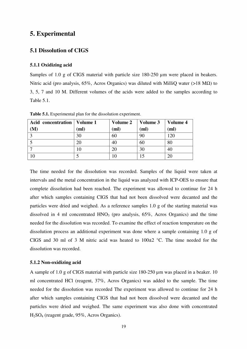
Samples of 1.0 g of CIGS material with particle size 180-250 µm were placed in beakers.
Nitric acid (pro analysis, 65%, Acros Organics) was diluted with MilliQ water (>18 MΩ) to
3, 5, 7 and 10 M. Different volumes of the acids were added to the samples according to
Table 5.1.
Table 5.1. Experimental plan for the dissolution experiment.
Acid concentration
(M)
Volume 1
(ml)
Volume 2
(ml)
Volume 3
(ml)
Volume 4
(ml)
3 30 60 90 120
5 20 40 60 80
7 10 20 30 40
10 5 10 15 20
The time needed for the dissolution was recorded. Samples of the liquid were taken at
intervals and the metal concentration in the liquid was analyzed with ICP-OES to ensure that
complete dissolution had been reached. The experiment was allowed to continue for 24 h
after which samples containing CIGS that had not been dissolved were decanted and the
particles were dried and weighed. As a reference samples 1.0 g of the starting material was
dissolved in 4 ml concentrated HNO3 (pro analysis, 65%, Acros Organics) and the time
needed for the dissolution was recorded. To examine the effect of reaction temperature on the
dissolution process an additional experiment was done where a sample containing 1.0 g of
CIGS and 30 ml of 3 M nitric acid was heated to 100±2 °C. The time needed for the
dissolution was recorded.
5.1.2 Non-oxidizing acid
A sample of 1.0 g of CIGS material with particle size 180-250 µm was placed in a beaker. 10
ml concentrated HCl (reagent, 37%, Acros Organics) was added to the sample. The time
needed for the dissolution was recorded The experiment was allowed to continue for 24 h
after which samples containing CIGS that had not been dissolved were decanted and the
particles were dried and weighed. The same experiment was also done with concentrated
H2SO4 (reagent grade, 95%, Acros Organics).

20
The dissolution of metals in non-oxidizing acids can be facilitated by addition of
hydrogen peroxide. To examine this method H2O2 (pro analysis, 30%, Scharlau) was added to
samples consisting of 1.0 g of CIGS material, with particle size 180-250 µm, and 10 ml
concentrated HCl (reagent, 37%, Acros Organics). The samples were stirred with a magnetic
bar at 300 rpm. One of the samples was heated to 100±2 °C prior to addition of H2O2, while
the other sample was kept at room temperature. The H2O2 was added in portions off 0.5 ml
until all material was dissolved. The gas evolving after each addition was allowed to leave the
vessel before a new addition was made. The volume of H2O2 needed for the dissolution was
recorded. The same experiment was repeated with concentrated H2SO4 (reagent grade, 95%,
Acros Organics).
5.2 Reduction of CIGS - hydrogen selenide
5.2.1 Reduction of CIGS with hydrogen gas
A sample of 15 g of the starting material with a particle size of 125-180µm was placed in a
fluidized bed batch reactor in a vertical tube furnace. The reactor was made from an 820 mm
long quartz tube fitted with a porous quartz plate of 30 mm in diameter placed 370 mm from
the bottom of the tube. The temperature in the reactor was controlled with thermocouples
inserted into the reactor through thin glass tubes. A gas mixture of 5vol% H2 and 95vol% N2
gas was passed through the reactor from the bottom at a flow rate of 600 ml/min. The
temperature in the reactor was set to 520 °C. The gas from the reactor was analyzed with gas-
MS. The gas not passing into the gas-MS was bubbled through two Drechsel bottles each
filled with 100 ml 0.5 M CuSO4 in order to trap any residual H2Se. The hydrogen selenide
reacts with Cu2+
in the solution forming black copper selenide that can easily be detected,
collected and analyzed. The copper solution was prepared from CuSO4 (puriss, Fluka) and
MilliQ water (>18 MΩ). After 20 min the experiment was terminated.
The gas was changed to 100vol% H2 gas at a flow rate of 274 ml/min. Due to
technical problems the gas-MS was removed and instead three Drechsel bottles each filled
with 100 ml 0.5 M CuSO4 was used to trap H2Se formed during the experiment, see figure
5.1.

21
250
200
150
100
50
H2/N2
or H2
Tube furnace
Temperature
control
Temperature
control
Figure 5.1. Experimental setup for the fluidized bed batch reactor reduction experiments.
The furnace was heated from 300±5 to 650±5 °C in steps of 50±5 °C. Each temperature was
maintained for 10 minutes. During the experiment the Drechsel bottles were observed for any
formation of black copper selenide. After the experiment the residue was analyzed with ICP-
OES and the composition was compared with the composition of the starting material. Any
precipitation formed was analyzed with ICP-OES to determine the substance.
5.2.2 Reduction of CIGS with sodium borohydride (NaBH4)
A sample of 1.0 g of CIGS was dissolved in hydrogen chloride and hydrogen peroxide (as
described above). After the complete reaction the solution was heated for 10 min to allow all
H2O2 to decompose. The solution was placed in a reaction flask and 0.5 g of sodium
borohydride (>98.5%, Sigma Aldrich) was added in portions of 0.02 g. The reaction flask
was connected via plastic tubing to two Drechsel bottles each filled with 100 ml 0.5 M
CuSO4. The copper solution was prepared from CuSO4 (puriss, Fluka) and MilliQ water (>18
MΩ). During the reaction the Drechsel bottles were observed for formation of copper
selenide. Any precipitation formed was analyzed with ICP-OES to determine the substance.

22
A sample of 1.0 g of CIGS was dissolved in hydrogen chloride and hydrogen
peroxide (as described above). To the solution 10 ml of 10 M NaOH was added to remove the
copper. The NaOH solution was prepared from NaOH (98%, Acros Organics) and MilliQ
water (>18 MΩ). The precipitate formed was decanted. Sodium hydroxide solution was
added until no more precipitate was formed. The remaining liquid was placed in a reaction
flask and 0.5 g of sodium borohydride (>98.5%, Sigma Aldrich) was added in portions of
0.02 g. The reaction flask was connected via plastic tubing to two Drechsel bottles each filled
with 100 ml 0.5 M CuSO4. The copper solution was prepared from CuSO4 (puriss, Fluka) and
MilliQ water (>18 MΩ). During the reaction the Drechsel bottles were observed for
formation of copper selenide. Any precipitation formed was analyzed with ICP-OES to
determine the substance.
5.2.3 Reduction of CIGS with ammonia and hydrogen peroxide
Hydrogen peroxide (pro analysis, 30%, Scharlau) and ammonia (pro analysis, 25%, Fischer)
were used to prepare 50 ml of a solution containing 25vol% hydrogen peroxide and 3vol%
ammonia. A sample of 1.0 g of CIGS with particle size 180-250 µm was placed in a reaction
flask. The solution was added to the flask in portions of 10 ml. After each addition the
reaction was allowed to settle before another addition was made. During the reaction the
Drechsel bottles were observed for formation of copper selenide. Any precipitate formed was
analyzed with ICP-OES to determine the substance.
5.3 Distillation of selenium dioxide
5.3.1 Oxidation experiment
A sample of 13.5 g of crushed CIGS, with the particle size distribution given in Table 4.1,
was placed in a furnace boat. The furnace boat was placed in a tube furnace and heated
together with oxygen gas (99%, AGA) with a flow rate of 200 ml/min, see Figure 5.2.

23
250
200
150
100
50
O2
Cooling water Tube furnace
Figure 5.2. Experimental setup for oxidation experiments in the tube furnace.
The temperature in the furnace was regulated with a thermocouple on the outside of the
quartz tube. The oxygen gas was passed (from right to left) through the quartz tube placed in
the tube furnace. The formed selenium dioxide was sublimed outside the furnace (on the left).
After the tube furnace, the gas was cooled in a cooler and then bubbled through a beaker
containing MilliQ water (>18 MΩ) to trap any remaining selenium dioxide. A series of
experiments was performed where the tube furnace was heated to 500, 600, 700, 800, 900
and 1000±10 °C for 24 h. The composition of the residue was analyzed with ICP-OES and
the selenium content was compared with the selenium content of the starting material. The
residues and the starting material were also analyzed with XRD. The selenium dioxide from
the reaction was analyzed with ICP-MS to determine the purity with respect to the critical
impurities (Cr, Mn, Fe, Ni, Zn) along with the level of separation from copper, indium and
gallium. To determine the accuracy of the ICP-OES and ICP-MS measurements triplicates
were analyzed.
5.3.2. Reduction of selenium dioxide – Riley reaction (Oxidation of deoxybenzoin to
benzil)
For the reduction experiment selenium dioxide from the oxidation of CIGS at 1000° C was
used. 7 ml glacial acetic acid (pro analysis, 100%, Merck) was used to dissolve 2.00 g (0.018
mol) of selenium dioxide and 3.54 g (0.018 mol) deoxybenzoin (98%, Acros organics). The
solution was refluxed for 3 h at 126±2 °C. After cooling the liquid was decanted from the
solid selenium formed during the reaction. Dietylether (99+%, Acros organics) was used to
wash the selenium and to extract the organic product from the acetic acid. After the extraction
MilliQ water (>18 MΩ) and a saturated solution of sodium bicarbonate was used to wash the

24
organic product. A final wash with brine and drying with sodium sulphate was done before
the product was concentrated under reduced pressure. The selenium from the reaction was
analyzed with ICP-MS to determine the purity with respect to the critical impurities (Cr, Mn,
Fe, Ni, Zn) along with the level of separation from copper, indium and gallium. The organic
product was analyzed with GC-MS to determine the purity. To determine the accuracy of the
ICP-OES and ICP-MS measurements triplicates were analyzed.
5.3.3 Reduction of selenium dioxide – Sulphur dioxide
A sample 1.00 g (0.009 mol) of selenium dioxide from the oxidation of CIGS at 1000° C was
used dissolved in 50 ml MilliQ water (>18 MΩ) in a Drechsel bottle. After heating of the
solution to 80±2°C sulphur dioxide gas (99.8%, AGA) at a flow rate of 40 ml/min was
bubbled through the solution. The reaction was allowed to continue for 15 min after which
the selenium was separated from the liquid. MilliQ water (>18 MΩ) water was used to wash
the selenium before it was dried and weighed. The selenium from the reaction was analyzed
with ICP-MS to determine the purity with respect to the critical impurities (Cr, Mn, Fe, Ni,
Zn) along with the level of separation from copper, indium and gallium. To determine the
accuracy of the ICP-OES and ICP-MS measurements triplicates were analyzed.

25
6. Results and discussion
6.1 Dissolution of CIGS
6.1.1 Oxidizing acid
CIGS was readily dissolved in 4 ml concentrated nitric acid in less than 10 minutes. The
result from the dissolution experiments with lower acid concentrations can be seen in Table
6.1.
Table 6.1. Results from dissolution of CIGS material in nitric acid.
Acid concentration
(M)
Acid volume
(ml)
Time for complete
dissolution
Remaining material*
(wt%)
3 30 - 88.4
3 60 - 79.7
3 90 - 71.3
3 120 - 84.8
5 20 - 24.1
5 40 - 18.1
5 60 - 13.4
5 80 - 34.0
7 10 - 9.9
7 20 - 5.9
7 30 <24 h 0
7 40 6 h 0
10 5 < 24 h 0
10 10 15 min 0
10 15 10 min 0
10 20 5 min 0
*The weight of the starting material (1.0 g) remaining after 24 h dissolution
From the table it can be seen that at least 10 ml of 10 M acid was needed for quick
dissolution. Larger volumes, 30ml or more, of 7 M acid also dissolved the CIGS material, but
several hours were needed before the dissolution was complete. None of the samples treated
with acid of lower concentration were completely dissolved. One thing worth noticing is that
larger acid volume did not always lead to better dissolution. The samples treated with the
largest amounts of 3 M and 5 M acid was not dissolved to the same extent as the samples

26
treated with less acid. This might be due to inadequate mixing of those samples because of
the large liquid volume.
Heating improved the dissolution process and 40 ml of 3 M acid dissolved the sample in 3 h.
6.1.2 Non-oxidizing acids
Neither concentrated hydrochloric nor concentrated sulphuric acid dissolved the CIGS
material completely. After 24 h in hydrochloric acid 96wt% of the material had not been
dissolved. The dissolution in sulphuric acid was even lower and 97wt% of the material still
remained after the test. At room temperature the CIGS material was dissolved in hydrochloric
acid after addition of 4 ml hydrogen peroxide. The dissolution was completed in 25 minutes.
This means that CIGS can be dissolved in a non-oxidizing acid if an oxidizing agent is added.
This makes reduction of the dissolved specimen, which is impossible if an oxidizing acid is
used, possible. An elevated temperature (100 °C) did not reduce the amount of hydrogen
peroxide or time needed for dissolution. The dissolution of CIGS in sulphuric acid was
competed after addition of 11 ml hydrogen peroxide during 50 minutes. The reaction upon
addition of hydrogen peroxide to the sulphuric acid solution was much more violent
compared to the reaction when hydrochloric acid was used. At 100 °C the amount of
hydrogen peroxide needed for the dissolution was reduced to 8 ml and the time was reduced
to 40 minutes. It was concluded that hydrochloric acid was more suitable for the dissolution
than sulphuric acid. Hydrochloric acid in combination with hydrogen peroxide was therefore
used for dissolution for the sodium borohydride reduction experiments.
6.2 Reduction of CIGS - hydrogen selenide
6.2.1 Reduction of CIGS with hydrogen gas
During the first part of the experiment no hydrogen selenide could be detected by the gas-
MS. There was also no black copper selenide forming in the Drechsel bottles after the gas-
MS. It was concluded that no hydrogen selenide was formed under the set conditions.
Therefore the concentration of hydrogen gas was increased and a larger temperature interval
was investigated. During this part of the experiment the gas-MS was removed due to
technical problems and all the gas was led through the copper sulphate solution instead. No
copper selenide was formed in the Drechsel bottles, at any of the tested temperatures. The
ICP-OES analysis of the CIGS material after the experiment showed no change in selenium
content compared to the starting material. The result from this experiment shows that

27
hydrogen selenide could not be formed when heating CIGS in hydrogen gas. It was
concluded that in order for the reaction to work a catalyst is needed. Since no catalyst was
available the method was abandoned.
6.2.2 Reduction of CIGS with sodium borohydride
No hydrogen selenide was formed from addition of sodium borohydride to the CIGS solution.
Instead red selenium was precipitated from the solution. This might be due to the interference
of copper ions with the reduction of selenium to hydrogen selenide. Therefore a new
experiment was performed where copper was precipitated as copper hydroxide prior to the
reduction, but this experiment did not result in hydrogen selenide formation upon addition of
sodium borohydride either. The reduction method was therefore concluded not to work on
CIGS materials.
6.2.3 Reduction of CIGS with ammonia and hydrogen peroxide
Upon the first addition of the ammonia and hydrogen peroxide solution to the dry CIGS
material 0.03 g of precipitate was formed in the first Drechsel bottle. ICP-OES analysis on
the precipitate confirmed that it was copper selenide and it could be concluded that a minor
amount of hydrogen selenide had been produced. Further addition of the ammonia and
hydrogen peroxide solution to the CIGS material did not yield any more hydrogen selenide.
6.3 Distillation of selenium dioxide
6.3.1 Oxidation experiment
The characterization of the starting material showed that it contained approximately 50wt%
selenium, Table 4.2. The analysis of the residues after the oxidation experiments revealed that
the selenium content decreased with higher oxidation temperature, see Figure 6.1. After
oxidation at 1000 °C the residue only contained 4wt% of the original amount of selenium.

28
Figure 6.1. The selenium content in the residues from the oxidation of CIGS as a function of
temperature. The selenium content is given in percent of the selenium content in the starting material.
Approximately 85wt% of the selenium removed from the CIGS material during each
oxidation experiment was recovered as selenium dioxide. To improve the yield another
design of the process equipment has to be developed. Analysis of different layers in the
residues after oxidation showed an increasing amount of selenium towards the bottom of the
reaction vessel. This indicates that mixing of the material could improve the selenium
separation.
Table 6.2. The composition of the top and bottom layers of the residue after oxidation at 1000 °C.
The uncertainty corresponds to one standard deviation.
Cu (wt%) In (wt%) Ga (wt%) Se (wt%)
Top layer 51.5±0.4 45.9±0.5 2.3±0.2 0.28±0.04
Bottom layer 27.0±0.2 56.1±0.7 11.4±0.1 5.5±0.1
The XRD analysis of the starting material and the residues, after oxidation at 800 and 1000
°C, showed that the material had been oxidized and that several different compounds had
been formed, see Figure 6.2.
0
10
20
30
40
50
60
70
80
90
100
400 500 600 700 800 900 1000 1100
Sel
eniu
m c
on
ten
t
(wt%
of
ori
gin
al
am
ou
nt)
Temperature (°C)

29
0
100
200
300
400
500
600
20 30 40 50 60 70
2
2
222
2
2
1
1
1
1 1
1
1 1
2
2 222
3
3
3
3
3
36 6
66
66 6
2
2
2
2
6
6
6
6
666 6 666
4 4 4
44 4 4 4
4
5555
34
4
4 4 4 444 5 4
1 1
2θ2θ2θ2θ
Inte
nsi
ty (
cp
s)
Figure 6.2. XRD patterns for starting material (bottom), residue after oxidation at 800 °C (middle)
and residue after oxidation at 1000 °C (uppermost). 1) Cu(In,Ga)Se2, 2) In2O3, 3) CuO, 4) CuGaInO4,
5) SeCu2, 6) Cu2In2O5.
The spectrum of the starting material shows the characteristic peeks of Cu(In,Ga)Se2 (1).
After the oxidation at 800 °C these peeks were reduced and the peeks indicating indium oxide
(2), copper oxide (3) and copper indium gallium oxide (4) can be seen. In addition copper
selenide (5) has been formed. The spectrum of the residue after oxidation at 1000 °C
indicates that there has been some recrystallization and indium copper oxide (6) has been
formed.
The solubility of the residue in nitric acid after oxidation was considerably lowered
with higher oxidation temperatures. To ensure complete dissolution of the residues aqua regia
had to be used. This means that further processing of the residues cannot be done by any
method requiring dissolution.
6.3.2. Reduction of selenium dioxide – Riley reaction (Oxidation of deoxybenzoin to
benzil)
The reaction gave 1.19 g of selenium corresponding to a yield of 90.7wt% and 3.1 g of the
organic product equivalent to a yield of 96.6wt%. The GC-MS analysis showed that the
formed benzil was pure from organic impurities, Figure 6.3 and 6.4.

30
Figure 6.3. GC-MS analysis of mixture containing deoxybenzoin and benzil. The retention time was
32.69 min for deoxybenzoin and 34.19 min for benzil. The peek after 9.40 min was determined to be
diacetone alcohol (2-Pentanone, 4-hydroxy-4-methyl), a contamination commonly found in acetone.
Acetone was used for dilution of the samples. The small peeks after 35 min are silicon compounds
from the column.
Figure 6.4. GC-MS analysis of organic product from the Riley reaction. The peek after 34.16 min
shows that the sample only contained benzil.
6.3.3 Reduction of selenium dioxide – Sulphur dioxide
During the reaction selenium dioxide was reduced to red selenium which upon heating to 80
°C was transformed to black selenium. The reaction was completed in 10 minutes and yielded
0.67 g of selenium corresponding to 93.8wt% of the selenium in the selenium dioxide. The

31
selenium content of the liquid after the reduction was determined to be less than 1.4wt%. To
improve the yield the collection of the selenium has to be improved.
6.3.4 Purity of the recycled selenium
The critical impurities in solar cells are chromium, manganese, iron, nickel and zinc. The
purity of the recycled selenium was analyzed with respect to these elements along with
copper, indium and gallium. The selenium from both reduction experiments and the selenium
dioxide from the oxidation test at 1000 °C were analyzed. The results from the ICP-MS
measurements were used to calculate the concentrations of the impurities in the selenium, see
Table 6.3.
Table 6.3. The concentration of impurities in the recycled selenium. The uncertainty corresponds to
one standard deviation.
Cr
(ppm)
Mn
(ppm)
Fe
(ppm)
Ni
(ppm)
Zn
(ppm)
Cu
(ppm)
Ga
(ppm)
In
(ppm)
Selenium
dioxide
0.17
±0.01
<0.1 <50 0.26
±0.01
0.30
±0.01
5.49
±0.22
0.35
±0.01
3.57
±0.22
Selenium - Riley
reaction
0.79
±0.03
<0.1 <50 0.51
±0.02
0.43
±0.02
13.5
±2.86
3.45
±0.26
6.55
±0.94
Selenium -
Sulphur dioxide
reaction
0.23
±0.01
<0.1 <50 0.34
±0.02
0.18
±0.02
5.58
±0.46
0.29
±0.01
2.04
±0.10
The concentration of all the critical impurities except iron was shown to be below 1ppm for
each element. Iron on the other hand could only be determined to be below 50ppm. The
higher detection limit for iron was due to the interference of iron with argon oxide in the ICP-
MS. The concentration of copper, indium and gallium were higher than the concentration of
the critical elements, but since they are used in the solar cell they do not pose a problem.
However, they were analyzed to give a measurement of the success of the separation method.
From the results shown in Table 6.3 the purity of the recycled selenium was determined, see
Table 6.4.

32
Table 6.4. The purity of the selenium dioxide from the oxidation and for the recycled selenium and
with respect to *Cr, Mn, Ni and Zn, ** Cr, Mn, Ni, Zn, Cu, Ga and In and ***all the analyzed
elements including iron. The uncertainty corresponds to one standard deviation.
Purity*
(wt%)
Purity**
(wt%)
Purity***
(wt%)
Selenium dioxide 99.99993
±2.07E-06
99,99899
±5.01E-05
> 99.99
Selenium - Riley
reaction
99.99983
±4.50E-06
99,99747
±3.02E-04
>99.99
Selenium -
Sulphur dioxide
reaction
99.99992
±2.81E-06
99,99913
±4.75E-05
>99.99
Due to the difficulty measuring iron the purity of the recycled selenium could only be
determined to be higher than 99.99wt%, but with respect to the other analyzed elements it
could be concluded that the purity was 5N or higher. It could also be concluded that the
sulphur dioxide reduction method gave a slightly higher purity.

33
7. Conclusions and process suggestions
7.1 Conclusions
It is possible to dissolve CIGS material in concentrated nitric acid, but not in concentrated
hydrochloric or sulphuric acid. Dissolution in nitric acid at room temperature could be
performed in 7 M acid, but at 100 °C only 3 M acid was needed. These results were not used
further since it was concluded that hydrometallurgical methods were not going to be used for
recycling of CIGS.
To dissolve CIGS in non-oxidizing acid, addition of an oxidizing agent (hydrogen
peroxide) is needed. Hydrochloric acid was determined to be the best choice for the
dissolution. This method was later used during one of the reduction experiments.
The possibility of reducing the selenium to hydrogen selenide was evaluated and
several different methods were tested. None of the methods yielded hydrogen selenide in
substantial amounts and the efforts were therefore abandoned.
The separation of selenium by distillation of selenium dioxide was proven to be
successful. Nearly all of the selenium was separated from the CIGS material after oxidation
at 1000 °C. Due to the high detection limit of iron with ICP-MS the purity of the recycled
selenium could only be determined to be higher than 4N with respect to all the critical
elements (Cr, Mn, Fe, Ni and Zn). However, with respect to the other critical elements the
purity was higher than 5N for all the analyzed selenium materials, enough for the material to
be used in the production of new semiconductor material for solar cell production. To more
accurately determine the iron concentration, neutron activation analysis will be done. Some
copper, indium and gallium could be detected in the selenium providing a purity level just
below 5N and the separation was considered to be successful. To reach even higher purities
the selenium could be passed through the oxidation process again.
The difficulty in dissolving the residue after the oxidation will have to be taken into
account when the next step in the recycling process is developed.

7.2 Process suggestions
Based on the results obtained
selenium from CIGS materials can be made. The most promising methods are the distillation
of selenium as selenium dioxide followed by reducti
by sulphur dioxide, see Figure 7.1.
Figure 7.1. Suggested process for separation of selenium from CIGS
34
he results obtained during this study a suggestion for a process for separation of
selenium from CIGS materials can be made. The most promising methods are the distillation
of selenium as selenium dioxide followed by reduction of the selenium dioxide to selenium
dioxide, see Figure 7.1.
Suggested process for separation of selenium from CIGS materials.
a process for separation of
selenium from CIGS materials can be made. The most promising methods are the distillation
on of the selenium dioxide to selenium

35
8. Future work
The results from the distillation experiments have been promising and the development of
this separation method will be continued with the optimization of the oxidation step with
regards to energy consumption and cost. Better mixing between the gas and the solid could
mean lower oxidation temperature, shorter reaction time and perhaps the possibility of useing
a cheaper gas. The possibility to use the process in industrial scale will be dependent on the
energy consumption and cost in relations to the purity of the recycled material compared to
other purification methods.
The next step in the development of a recycling method for CIGS will be to separate
the remaining elements in the residue from the oxidation step.

36

37
Acknowledgements
I would like to thank…
• my examiner Gunnar Skarnemark for good cooperation
• my supervisor Christian Ekberg for feedback and ideas
• all my colleagues at Industrial Materials Recycling and Nuclear Chemistry for
answering my questions and for good laughs around the coffee table
• Julia, Hanna, Elin, Emma, Sravya and Kristian for listening and helping
• my family for always believing in and supporting me – you mean more than I can say!
• all my friend. None mentioned, none forgotten.
• Midsummer AB for good collaboration, ideas and materials
• FORMAS and Energimyndigheten for funding this work

38

39
References
1. Armaroli, N. and Balzani, V., The Future of Energy Supply: Challenges and Opportunities.
Angewandte Chemie International Edition, 2007. 46(1-2): p. 52-66.
2. Lewis, N. S. and Nocera, D. G., Powering the planet: Chemical challenges in solar energy
utilization. Proceedings of the National Academy of Sciences, 2006. 103(43): p. 15729-
15735.
3. Becquerel, A. E., Mémoire sur les effets électriques produits sous l'influence des rayons
solaires. Comptes rendus hebdomadaires des séances de l'Académie des Sciences, 1839. 9: p.
561-567.
4. Fraas, L. and Partain, L. D., eds. Solar Cells and Their Applications. 2:nd ed. Wiley Series in
Microwave and Optical Engineering, ed. K. Chang. 2010, John Wiley & Sons: Hobroken,
New Jersey.
5. Miles, R. W., Hynes, K. M.and Forbes, I., Photovoltaic solar cells: An overview of state-of-
the-art cell development and environmental issues. Progress in Crystal Growth and
Characterization of Materials, 2005. 51(1-3): p. 1-42.
6. Goetzberger, A., Hebling, C.and Schock, H.-W., Photovoltaic materials, history, status and
outlook. Materials Science and Engineering: R: Reports, 2003. 40(1): p. 1-46.
7. Miles, R. W., Photovoltaic solar cells: Choice of materials and production methods. Vacuum,
2006. 80(10): p. 1090-1097.
8. Kippelen, B. and Bredas, J.-L., Organic photovoltaics. Energy Environ. Sci., 2009. 2(3): p.
251-261.
9. Hoppe, H. and Sariciftci, N. S., Organic solar cells: An overview. Journal of materials
research, 2004. 19(7): p. 1924-1945.
10. Cotal, H., Fetzer, C., Boisvert, J., Kinsey, G., King, R., Hebert, P., Yoon, H.and Karam, N.,
III-V multijunction solar cells for concentrating photovoltaics. Energy Environ. Sci., 2009.
2(2): p. 174-192.
11. Goncalves, L. M., Bermudez, V. d. Z., Ribeiro, H. A.and Mendes, A. M., Dye-sensitized solar
cells: a safe bet for the future. Energy Environ. Sci., 2008. 1(6): p. 655-667.
12. Mehta, S. 2009 Global PV cell and module production analysis. GTM Research, Greentech
media inc 2010. Available from: http://www.gtmresearch.com/report/2009-cell-and-module-
production-analysis.
13. Green, M. A., Thin-film solar cells: review of materials, technologies and commercial status.
J. Mater. Sci.: Mater. Electron., 2007. 18(Suppl. 1): p. S15-S19.
14. Miles, R. W., Zoppi, G.and Forbes, I., Inorganic photovoltaic cells. Materials Today, 2007.
10(11): p. 20-27.
15. Green, M. A., Estimates of Te and In prices from direct mining of known ores. Progress in
Photovoltaics: Research and Applications, 2009. 17(5): p. 347-359.
16. Critical raw materials for the EU - Report of the Ad-hoc Working Group on defining critical
raw materials. European Commission 2010. Available from:
http://ec.europa.eu/enterprise/policies/raw-materials/critical/index_en.htm.
17. Berger, W., Sapich, G.and Weimann, K. RESOLVED (Recovery of Solar Valuable Materials,
Enrichment and Decontamination), Techical Final Report LIFE04/ENV/D/00047. Federal
Institute for Materials Research and Testing 2008. Available from:
http://www.resolved.bam.de/eng_home-index.htm.
18. Midsummer AB. Elektronikhöjden 6, 175 43 JÄRFÄLLA, SWEDEN. +46-8-525 09 610.
http://www.midsummer.se/.
19. Smart, L. E. and Moore, E. A., Solid State Chemistry An Introduction, Third Edition 3rd
Edition. 3 ed. 2005, Boca Raton (FL): CRC Press.
20. Markvart, T., Castañer, L., Tom, M.and Luis, C., Principles of solar cell operation, in Solar
Cells: Materials Manufacture and Operation 2005, Elsevier Science: Oxford. p. 5-27.

40
21. Lundberg, O., Bodegård, M., Malmström, J.and Stolt, L., Influence of the Cu(In,Ga)Se2
thickness and Ga grading on solar cell performance. Progress in Photovoltaics: Research and
Applications, 2003. 11(2): p. 77-88.
22. Chopra, K. L., Paulson, P. D.and Dutta, V., Thin-film solar cells: an overview. Progress in
Photovoltaics: Research and Applications, 2004. 12(2-3): p. 69-92.
23. Drinkard Jr, W. F., Long, M. O.and Goozner, R. E. Recycling of CIS photovoltaic waste. US
Patent 5779877, July 14, 1998
24. Green, M. A., Emery, K., Hishikawa, Y., Warta, W.and Dunlop, E. D., Solar cell efficiency
tables (version 39). Progress in Photovoltaics: Research and Applications, 2012. 20(1): p. 12-
20.
25. Aberle, A. G., Thin-film solar cells. Thin Solid Films, 2009. 517(17): p. 4706-4710.
26. Patnaik, P., Handbook of Inorganic Chemicals. 2003, New York: McGraw-Hill.
27. Fthenakis, V., Sustainability of photovoltaics: The case for thin-film solar cells. Renewable
and Sustainable Energy Reviews, 2009. 13(9): p. 2746-2750.
28. Berger, W., Simon, F. G., Weimann, K.and Alsema, E. A., A novel approach for the recycling
of thin film photovoltaic modules. Resources Conservation and Recycling, 2010. 54(10): p.
711-718.
29. Bombach, E., Müller, A., Wambach, K.and Röver, I., Recycling of soalr cells and modules-
recent improvements, in Proceedings of the 20th European Photovoltaic Solar Energy
Conference. 2005: Barcelona, Spain.
30. Mezei, A., Ashbury, M., Canizares, M., Molnar, R., Given, H., Meader, A., Squires, K.,
Ojebuoboh, F., Jones, T.and Wang, W., Hydrometallurgical recycling of the semiconductor
material from photovoltaic materials - Part one: Leaching, in Hydrometallurgy 2008:
Proceedings of the Sixth International Symposium, C.A. Young, Editor. 2008, Society for
Mining, Metallurgy & Exploration Inc. p. 209.
31. Mezei, A., Ashbury, M., Canizares, M., Molnar, R., Given, H., Meader, A., Squires, K.,
Ojebuoboh, F., Jones, T.and Wang, W., Hydrometallurgical recycling of the semiconductor
material from photovoltaic materials - Part two: Metal recovery, in Hydrometallurgy 2008:
Proceedings of the Sixth International Symposium, C.A. Young, Editor. 2008, Society for
Mining, Metallurgy & Exploration. p. 224.
32. Shah, A., Torres, P., Tscharner, R., Wyrsch, N.and Keppner, H., Photovoltaic Technology:
The Case for Thin-Film Solar Cells. Science, 1999. 285(5428): p. 692-698.
33. Fathi, M. and Mougas, A., Recycling of a defective metal insulator semiconductor solar cell
by hot phosphoric acid. Journal of Renewable and Sustainable Energy, 2011. 3(1).
34. Frisson, L., Lieten, K., Bruton, T., De Clercq, K., de Moor, H., Goris, M., Benali, A.and
Aceves, O. Recent improvements in industrial PV module recycling. in 16th European
Photovoltaic Solar Energy Conference 2000. Glasgow, Scotland.
35. Klugmann-Radziemska, E., Ostrowski, P., Drabczyk, K., Panek, P.and Szkodo, M.,
Experimental validation of crystalline silicon solar cells recycling by thermal and chemical
methods. Solar Energy Materials and Solar Cells, 2010. 94(12): p. 2275-2282.
36. Pa, P. S., A Reclaiming Process for Solar Cell Silicon Wafer Surfaces. Journal of Nanoscience
and Nanotechnology, 2011. 11(1): p. 691-695.
37. Bohland, J. R. and Anisimov, I. I. Possibility of recycling silicon PV modules. in Proceedings
of the 26th IEEE Photovoltaic Specialists Conference. 1997. Anaheim, USA.
38. Yamashita, K., Miyazawa, A.and Sannomiya, H. Research and Development on Recycling
and Reuse Treatment Technologies for Crystalline Silicon Photovoltaic Modules. in
Photovoltaic Energy Conversion, Conference Record of the 2006 IEEE 4th World Conference
on. 2006.
39. Fallavollita, J. A. Methods and apparatus for recovery of silicon and silicon carbide from
spent wafer-sawing slurry. US 2011/0059002 A1, March 10, 2011
40. Grabbe, A. and Ragan, T. M. Method to recover and purify silicon from saw kerf. US
2010/0163462 A1, July 1, 2010
41. Hariharan, A. V. and Ravi, J. Method to convert waste silicon to high purity silicon. US
2010/0061913 A1, 2010

41
42. Lin, Y.-C., Wang, T.-Y., Lan, C.-W.and Tai, C. Y., Recovery of silicon powder from kerf loss
slurry by centrifugation. Powder Technology, 2010. 200(3): p. 216-223.
43. Moro, L., Xiaobing, X., Perez-Mariano, J., Kai, L., Dubois, L. H., Lochtenberg, B.and
Sanjurjo, A. Low-cost solar-grade silicon: Purification and consolidation of silicon fines from
wafering. in Photovoltaic Specialists Conference (PVSC), 2010 35th IEEE. 2010.
44. Tai, Y.-D. and Lin, Y.-C. Recovery of silicon and silicon carbide powder from kerf loss slurry
using particle phase-transfer method. US 2010/0284885 A1, November 11, 2010
45. Tsai, T.-H., Silicon sawing waste treatment by electrophoresis and gravitational settling.
Journal of Hazardous Materials, 2011. 189(1-2): p. 526-530.
46. Wu, Y.-F. and Chen, Y.-M., Separation of silicon and silicon carbide using an electrical
field. Separation and Purification Technology, 2009. 68(1): p. 70-74.
47. Zhang, L. and Ciftja, A., Recycling of solar cell silicon scraps through filtration, Part I:
Experimental investigation. Solar Energy Materials and Solar Cells, 2008. 92(11): p. 1450-
1461.
48. Seo, K. H., Kang, B. H.and Kim, K. Y., Fast melting and refining of recycled silicon powders
from the wafer back grinding process for solar cell feedstock, in Materials Science Forum.
2012. p. 859-864.
49. Fthenakis, V. M., Morris, S. C., Moskowitz, P. D.and Morgan, D. L., Toxicity of cadmium
telluride, copper indium diselenide, and copper gallium diselenide. Progress in Photovoltaics:
Research and Applications, 1999. 7(6): p. 489-497.
50. Goozner, R. E., Drinkard, W. F., Long, M. O.and Byrd, C. M. A process to recycle thin film
PV materials. in Proceedings of the 26th IEEE Photovoltaic Specialists Conference. 1997.
Anaheim, USA.
51. Goozner, R. E., Long, M. O.and Drinkard Jr, W. F. Recycling of CdTe photovoltaic waste. US
Patent 5997718, December 7, 1999
52. Bohland, J., Anisimov, I., Dapkus, T., Sasala, R., Samigielski, K.and Kamm, K. Recaliming
metallic material from an article comprising a non-metallic friable substrate. US Patent
6129779, October 10, 2000
53. Fthenakis, V. M. and Wang, W., Extraction and separation of Cd and Te from cadmium
telluride photovoltaic manufacturing scrap. Progress in Photovoltaics: Research and
Applications, 2006. 14(4): p. 363-371.
54. Bradwell, D. J., Osswald, S., Wei, W., Barriga, S. A., Ceder, G.and Sadoway, D. R.,
Recycling ZnTe, CdTe, and other compound semiconductors by ambipolar electrolysis.
Journal of the American Chemical Society, 2011. 133(49): p. 19971-19975.
55. Menezes, S., Electrochemical approach for removal, separation and retrieval of CdTe and
CdS films from PV module waste. Thin Solid Films, 2001. 387(1-2): p. 175-178.
56. Kushiya, K., Ohshita, M.and Tanaka, M. Development of recycling and reuse technologies for
large-area Cu(InGa)Se2-based thin-film modules. in Proceedings of the 3rd World
Conference on Photovoltaic Energy Conversion. 2003. Osaka, Japan.
57. Menezes, S., Electrochemical solutions to some thin-film PV manufacturing issues. Thin
Solid Films, 2000. 361-362: p. 278-282.
58. Menezes, S., Investigation of electrochemical processes for synthesis and removal of CuInSe2
thin films. Mater. Res. Soc. Symp. Proc., 1996. 426(Thin Films for Photovoltaic and Related
Device Applications): p. 189-194.
59. SENSE (Sustainability EvaluatioN of Solar Energy systems) - Recycling of Production Waste.
Zentrum fuer Sonnenenergie- und Wasserstoff-Forschung 2002. Available from:
http://www.sense-eu.net.
60. Wickstrom, T., Lund, W.and Bye, R., Hydride generation atomic absorption spectrometry
from alkaline solutions: determination of selenium in copper and nickel materials. Journal of
Analytical Atomic Spectrometry, 1991. 6(5): p. 389-391.
61. Larsen, E. H., Hansen, M., Fan, T.and Vahl, M., Speciation of selenoamino acids, selenonium
ions and inorganic selenium by ion exchange HPLC with mass spectrometric detection and its
application to yeast and algae. Journal of Analytical Atomic Spectrometry, 2001. 16(12): p.
1403-1408.

42
62. Greenwood, N. and Earnshaw, A., Chemistry of the Elements, Second Edition. 1997, Oxford,
England: Butterworth-Heinemann.
63. Sonoda, N., Kondo, K., Nagano, K., Kambe, N.and Morimoto, F., CARBON-MONOXIDE
WATER AS A REDUCING AGENT - FORMATION OF SELANE FROM SELENIUM.
Angewandte Chemie-International Edition in English, 1980. 19(4): p. 308-309.
64. Smith, A. E., Interferences in the determination of elements that form volatile hydrides with
sodium borohydride using atomic-absorption spectrophotometry and the argon-hydrogen
flame. Analyst, 1975. 100(1190): p. 300-306.
65. Ayers, W. M. Method and apparatus for constant composition delivery of hydride gases for
semiconductor processing. US6080297, 1999
66. Bastide, S., Hügel, P., Lévy-Clément, C.and Hodes, G., Electrochemical preparation of H2S
and H2Se. Journal of The Electrochemical Society, 2005. 152(3).
67. Mond, L., Langer, C.and Quincke, F., Action of carbon monoxide on nickel. Journal of the
Chemical Society, Transactions, 1890. 57: p. 749-753.
68. Lascelles, K., Morgan, L. G.and Nicholls, D., Nickel Compounds, in Ullmann's Encyclopedia
of Industrial Chemistry. 2000, Wiley-VCH Verlag GmbH & Co. KGaA.
69. Waitkins, G. R. and Clark, C. W., Selenium Dioxide: Preparation, Properties, and Use as
Oxidizing Agent. Chemical Reviews, 1945. 36(3): p. 235-289.
70. Riley, H. L., Morely, J. F.and Friend, N. A. C., Selenium Dioxide, a New Oxidising Agent.
Part I. Its Reaction with Aldehydes and Ketones. Journal of the Chemical Society, 1932: p.
1875-1883.
71. Rabjohn, N., Selenium dioxide oxidation, in Organic chemistry. 1976, John Wiley & Sons,
Inc: New York. p. 262-407.
72. Sharpless, K. B. and Gordon, K. M., Selenium dioxide oxidation of ketones and aldehydes.
Evidence for the intermediacy of .beta.-ketoseleninic. Journal of the American Chemical
Society, 1976. 98(1): p. 300-301.
73. Handwerk, E. C. and Monson, W. T. Selenium recovery process. US2948591, 1960
74. Rao, S. R., Chapter 10 Resource recovery from process wastes, in Waste Management Series.
2006, Elsevier. p. 375-457.
75. Fthenakis, V., Wang, W.and Kim, H. C., Life cycle inventory analysis of the production of
metals used in photovoltaics. Renewable Sustainable Energy Rev., 2009. 13(3): p. 493-517.
76. Dean, J. R., Practical Inductively Coupled Plasma Spectroscopy. 2005: John Wiley & Sons,
Ltd.
77. Harris, D. C., Quantitative Chemical Analysis. 7:th ed. 2007, New York: W. H. Freeman and
Company.
78. Joint Committee of Powder Diffraction Standards, JCPDS-ICCD: PDF-4 release 2010. 2010,
Philadelphia, USA.

43
List of Abbreviations and Terms
PV Photovoltaic
CIGS Copper Indium Gallium Selenide (Cu(In,Ga)Se2)
CdTe Cadmium Telluride
CdS Cadmium Sulphide
4N 99.99%
5N 99.999%
TCO Transparent Conductive Oxide
ICP-OES Inductively Coupled Plasma – Optical Emission Spectroscopy
ICP-MS Inductively Coupled Plasma – Mass Spectroscopy
Gas-MS Gas – Mass Spectroscopy
GC-MS Gas Chromatography – Mass Spectroscopy
XRD X-Ray Diffraction