Embed Size (px)
Citation preview

Rev.1.12.09.10 1
ThermoFlex®
Installation Guidelines
for Laminated & Engineered Wood Floors
Revolutionary ThermoFlex™ laminate floor underlayment now makes it possible to enjoy the luxury of safe and soothing warmth under floating laminate and wood floors:
There is no easier way to heat your floor than with ThermoFlex™.
No metal heating wires provides safest heat possible for warm floors.
Complements home heating system making rooms more comfortable.
Allows for reducing the central heating thermostat & saves energy.
Installs over all underlayments for floating floors.
Made with ThermoSoft® FiberThermic® Heating Elements. US Patent # US 6,563,094 B2
ThermoFlex™ is available in 120 Volt and 240 Volt in the following sizes:
Volts Model Dimensions Square
Feet Watts Amps
120 TX1505-120 1.5’ x 5’ 7.5 59 .5
120 TX1510-120 1.5’ x 10’ 15 122 1.0
120 TX3005-120 3’ x 5’ 15 131 1.1
120 TX3010-120 3’ x 10’ 30 269 2.2
240 TX1510-240 1.5 x 10’ 15 122 .5
240 TX1520-240 1.5’ x 20’ 30 247 1.0
240 TX3005-240 3’ x 5’ 15 131 .5
240 TX3010-240 3’ x 10’ 30 268 1.1
240 TX3015-240 3’ x 15’ 45 408 1.7
240 TX3020-240 3’ x 20’ 60 543 2.2
Conforms to UL
Safety Standard 1693
**To use ThermoFlex as the sole room heating source, make sure your BTU requirements are met by the total Watts of ThermoFlex installed. 1,000 Watts = 3,412 BTU’s/hour.
Thermosoft International Corporation 701 Corporate Woods Parkway • Vernon Hills, IL 60061
Telephone 847-279-3800 • Facsimile 847-279-8845
www.thermosoft.com

Rev.1.12.09.10 2
Cautions: THIS EQUIPMENT SHALL BE INSTALLED ONLY BY QUALIFIED PERSONNEL WHO ARE FAMILIAR WITH
THE CONSTRUCTION AND OPERATION OF THE APPARATUS AND THE RISKS INVOLVED.
THE INSTALLATION OF THIS HEATING PRODUCT SHALL BE IN ACCORDANCE WITH THE
MANUFACTURER’S INSTRUCTIONS AND LOCAL AND NATIONAL CODES.
IN CANADA, THE INSTALLATION SHALL BE MADE ACCORDING TO THE PROVISIONS OF SECTION 62 OF
THE CANADIAN ELECTRICAL CODE, PART 1.
WARNING - AS DESCRIBED IN THESE INSTRUCTIONS, LEAD WIRES ARE NOT TO BE ROUTED OVER
PADS OR COME INTO CONTACT WITH THE HEATING ELEMENTS AS DAMAGE TO SUPPLY CONDUCTOR
INSULATION MAY OCCUR IF CONDUCTORS ARE ROUTED TO CONTACT HEATING ELEMENTS. REFER
TO INSTALLATION INSTRUCTIONS FOR RECOMMENDED MEANS OF ROUTING SUPPLY CONDUCTORS.
THE TYPE AND THICKNESS OF FLOOR COVERING MATERIALS USED WITH THIS PRODUCT MUST NOT
EXCEED A THERMAL INSULATION “R” VALUE OF 2.0.
CAUTION: USE COPPER ONLY AS SUPPLY CONDUCTORS.
THERE ARE NO SPECIAL CRIMPING TOOLS REQUIRED FOR THIS PRODUCT.
ATTENTION: CONIFIER L’INSTALLATION DE CE MATERIEL AUN PERSONNEL QUALIFIE, QUI CONNAIT
BIEN L’APPAREIL ET LES RISQUES INHERENTS.
CE SYSTEME DE PANNEAUX CHAUFFANTE DOIT ETRE INSTALLECONFORMEMENT AUX EXIGENCES DE
TOUS LES POUVOIRS DE REGLEMENTATION.
ATTENTION: UTILISER DES CONDUCTEURS EN CUIVRE SEULEMENT.
OVERVIEW:
ThermoFlex™ may be used in three types of flooring applications:
1. Floating laminate and floating wood floors.*
2. Glued-down engineered and solid wood floors.
3. Ceramic tile, marble, porcelain, slate, stone and other cementitious floor coverings.
4. Carpet and vinyl floors after first covering ThermoFlex with self-leveling cement.
• Do not install ThermoFlex in walls.
• For Installations not covered in these directions, consult customer service before installation.
• Installations not performed within the stated manner may void all warranties.
Refer to Floor Covering Manufacturer’s specifications for compatibility of their product over radiant heat before installation.
Each of the above applications requires 5 basic steps:
A. Electrical Rough-In
B. Planning & Preparation
C. ThermoFlex Installation
D. Floor Covering Installation
E. Final Wiring & Connection
Rev.1.12.09.10 3
1. FLOATING HARD SURFACE FLOORS (including laminate, wood and interlocking tile)
1-A Electrical Rough-In
Install GFCI Breaker – (Over-current Protection)
1. ThermoFlex™ must be installed with a ground fault circuit interrupter (GFCI) unless your ThermoFlex model is equipped with ground wire in which case only wet area installations (kitchen, bath) require GFCI. We recommend installing ThermoFlex
with our programmable thermostat (purchased separately) with a built-in GFCI. If you are not using a thermostat with GFCI already built-in, then install a dedicated, indicating-type GFCI. This GFCI serves as a local disconnect.
• Note: Follow all local building and electrical codes. • It is possible to branch from an existing circuit if the Amps provided by the circuit are sufficient to supply the Amp load of
the floor heating mats and all other appliances that are or will be connected to the circuit. If the Amp supply is not sufficient, install a dedicated circuit.
• Consult with a qualified electrician to determine if the circuit can handle the load and if the circuit is GFCI-protected. The size of the breaker is determined by the total Amp load of the heated mats. You may need multiple breakers, multiple thermostats or a contactor/relay for systems larger than 15 Amps.
Install Electrical Boxes
2. Thermostats are usually located near the power leads. However, they can be located almost anywhere, because the power leads and the sensor wire can be routed to electrical junction boxes and extended to a location outside the heated room (such as a utility room). 3. For the programmable thermostat, install a 1-gang (2” wide) or 2-gang (4” wide) electrical box with a 1-gang mud ring. (Note: the 4” box provides more room to work with multiple lead wires). If using our manual thermostat, Model MTC, install a 2.25” wide or 4” electric box. Electrical boxes are typically located approximately 5’ from the floor for readability. 4. The floor sensor wire can be extended up to 50’ (maximum) if necessary.
Bottom Plate Work
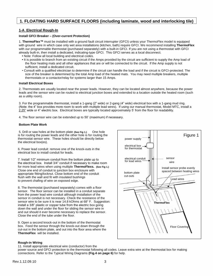
5. Drill or saw holes at the bottom plate (See Fig 1.) One hole is for routing the power leads and the other hole is for routing the thermostat sensor wire. These holes should be directly below the electrical box(es). 6. Power lead conduit: remove one of the knock-outs in the electrical box to install conduit for leads. 7. Install 1/2” minimum conduit from the bottom plate up to the electrical box. Install 3/4” conduit if necessary to make room for more lead wires when using multiple ThermoFlexs. (See Fig 1.)
Close one end of conduit to junction box enclosure with
power supply
electrical box for thermostat
electrical conduit for lead wires
sensor
wire
Figure 1
appropriate fitting/locknut. Close bottom end of the conduit flush with the wall and fit with insulated bushings to prevent chafing of wire on exposed edge. 8. The thermostat (purchased separately) comes with a floor sensor. The floor sensor can be installed in a conduit separate from the power lead wire conduit although installation of the sensor in conduit is not necessary. Check the resistance of the sensor wire to be sure it is near 14.8 kOhms at 68° F. Suggestion: install a 3/8” plastic or copper tube from the electric box going down the wall and under the floor for sliding the sensor wire in and out should it ever become necessary to replace the sensor. Close the end of the tube under the floor. 9. Open a second knock-out in the bottom of the thermostat box. Feed the sensor through the knock-out down through the cut-out in the bottom plate, and out into the floor area where the
ThermoFlex will be installed.
Rough-in Wiring 11. Install appropriate electrical wire (conductor) from the
ThermoFlex
Floor Covering
power source and GFCI protection to the thermostat following all codes. Leave extra wire at the thermostat box for making connections. Refer to the Typical Wiring Diagrams (Fig.4 on page 6) for help.
bottom plate cut-outs
Lead wires
Install sensor probe evenly spaced between heating wires

Rev.1.12.09.10 4
Installing a Relay (Contactor) 12. Depending on the Amp requirements of multiple ThermoFlexs™, a relay may be required. Consult with an electrician to determine the type and size of relay required.
1-B Planning & Preparation 1. Plan the heated area of the floor so that the desired traffic areas can be heated with a combination of the available
ThermoFlex sizes. When planning your heated floor area, keep the following important points in mind: • Do not cut ThermoFlex or cut or pierce ThermoFlex’s heating wires. • Do not overlap ThermoFlex. • Do not duct tape over ThermoFlex’s heating wires. • Do not power 120V ThermoFlexs with 240 Volt power. Power 120V mats with 120V power and 240V mats with 240V
power. • Lead wires should run along the end of the mats to the nearest wall and electrical junction box. Check local and national codes regarding the use of conduit from the floor to the junction box. A qualified electrician must make all electrical connections. • Do not run lead wires over or under mats. Run lead wires between mats and between underlayment padding. • Do not install ThermoFlex heaters under cabinets, built-ins or furniture with a solid surface base. Excessive heat will accumulate under these items and may damage ThermoFlex’s heating elements.
2. With all approved floor types, be sure the subfloor surface is clean and dry*. The floor must be completely swept of all debris including all nails, dirt, wood and other construction debris. Make absolutely sure there are no objects on the floor that might damage the ThermoFlex wires.
*Where concrete slabs are subject to excessive moisture, a calcium chloride moisture test is recommended. Vapor emission
readings in excess of 3 lbs. per 1,000 square feet in 24 hours may require additional protection such as a concrete sealant or 6 mil (.006”) polyethylene sheeting (vapor barrier). If in doubt, install 6 mil (.006”) vapor barrier on the slab.
3. Before starting, remove the ThermoFlex from the box. Attach both lead wires (120V: black & white; 240V: black & red) to a
high quality digital ohmmeter to measure the resistance. Compare the resistance you measured to the resistance recorded by the factory on the label attached to the heating mats. If the resistance is not within ±10% of the factory recorded resistance, call our customer service number for assistance. Damage may have occurred during shipping. Do not proceed with the installation. Keep a record of resistance measures as they will be needed for warranty purposes.
4. Leave the factory labels attached to the heating mats and the lead wires for later inspection. Save warning label #1 and place it inside the breaker panel to identify the radiant flooring circuit.
1-C ThermoFlex™ Installation
1. Lay flooring underlayment pad on subfloor according to the flooring manufacturer’s instructions. 1. Lay ThermoFlex over underlayment pad. (Photo 1) 2. Layout lead wires so they run to the nearest wall with an electrical box. (See Fig. 2 page 5.) Connections will be made later.
(Photo 2) Cut a strip out of the underlayment padding if necessary to lay the lead wires flat between the padding. 3. Allow approximately 1” of floor space between the wall and ThermoFlex to run the lead wires to the conduit. Use strips of
duct tape to hold lead wires in place – DO NOT STAPLE. 4. ThermoFlex should be completely flat. Do not overlap ThermoFlex. 5. Tape the seams with duct tape or other water and tear resistant, utility-grade, poly-coated cloth backed tape that has a very
aggressive adhesive. (Photo 3). Tape over the lead wires running between the padding. 6. Avoid taping over ThermoFlex’s heating wires. 7. The thermostat sensor wire should be routed up the wall to the thermostat electrical box. Place the tip of the sensor wire
evenly spaced between two ThermoFlex heating wires extending about 6”-12” into ThermoFlex. (Refer to Fig. 3 Sensor Wire Location on page 5.) It is acceptable to use a utility knife to notch out a 1/4” x 1” piece of ThermoFlex and the underlayment to imbed the sensor (DO NOT CUT THE HEATING WIRE). You can tape the sensor wire in place but do not tape over the sensor probe as this may cause heat build-up causing the thermostat to reduce power to ThermoFlex heating elements.
1-D Floating Laminate or Wood Floor Covering Installation
1. When installing the floor, be careful not to damage ThermoFlex’s heating elements. If the floor covering is not immediately
installed, protect ThermoFlex with corrugated box material, carpet, luan plywood or similar material. • Keep traffic to a minimum on installed ThermoFlex prior to floor covering installation. • Avoid dropping, rolling or dragging objects or tools over the heating elements. • Be careful that nails, screws or other fasteners do not penetrate the floor in the area of ThermoFlex. ThermoFlex’s
heating elements can be damaged by fasteners penetrating the floor. 2. Install the floating laminate or floating wood floor according to the flooring manufacturer’s instructions.
Photo1 Photo 2 Photo 3
Underlayment padding
Photo1
ThermoFlex

Rev.1.12.09.10 5
Figure 2
Thermostat
ThermoFlex®
ThermoFlex®
ThermoFlex®
butt together and
duct tape seams
Sensor Wire Location
Figure 3
Leave 1” space from the wall to run lead wires. Small
gaps around the perimeter do not need to be covered
by an underlayment.
* A contactor/relay may be required for large installations. Consult an electrician. ** Sensor can be run down the wall or in a separate conduit from the power leads.
Locate thermostat sensor probe equally spaced between two heating wires.
Tape wire in place.
Do not tape over sensor.
1-E Final Wiring & Connections
1. After installing your floor, use the ohmmeter to record the final resistance measurement of ThermoFlex . The
resistance must be within ±10% of the factory recorded resistance. If not, call our customer service number for
assistance. Damage may have occurred during floor installation. Keep a record of all three resistance measures as they
will be needed for warranty purposes. See Resistance Measures Chart, page 9. 2. Install the floor sensing thermostat in the 4” square electrical box according to the installation instructions provided with the thermostat. Connect the power mat leads, floor sensor, and power supply wiring as shown in the thermostat instructions and as diagramed on the back of the thermostat. For wiring diagrams, see Figure 4, page 6. 3. Route ThermoFlex lead wires up through the electrical conduit and into the 4” square thermostat box. Wire the leads in parallel (not series) 120V: black-black (line) and white-white (neutral); 240V black-black (line) and red-red (line). Then wire a short “pig-tail” (of correctly sized wire for the load) over to the thermostat. The number of conductors per connection must not exceed the amperage rating of the circuit or local or national codes. Field wiring must be 14 gauge or as otherwise appropriate for the Amp load of the installation as specified by local and national codes. 4. Use a 1-gang mud ring to mount the thermostat if using a 4” electrical box. 5. Indicate which circuits supply the ThermoFlex and retain the ETL labels for each ThermoFlex mat in a convenient location, ie., taped to the circuit breaker box, for reference by the electrical inspector or homeowner. Leave one ETL label attached to the ThermoFlex mat. Attached warning label #1 in a convenient location e.g., inside of breaker panel, or thermostat control door in the room where ThermoFlex is installed. 6. After all thermostatic controls are installed, power up the system to briefly test operation of all components. 7. Refer to instructions provided with the thermostatic controls for proper setting. Keep instructions in a safe place for future reference.
2. GLUED-DOWN ENGINEERED AND SOLID WOOD FLOORS
2-A Electrical Rough-In: See section 1-A.
2-B Planning & Preparation: See section 1-B.
2-C ThermoFlex™ Installation
Approved Surfaces for Applications: Plywood, wood, hardboard underlayment, association grade particleboard, concrete
above grade in the absence of excessive moisture and/or excessive alkali, and well-bonded VCT* and sheet vinyl* (non-embossed and non-cushioned). Sub-floor must meet NWFA (National Hardwood Flooring Association) and local building code standards for quality, thickness and maximum deflection. *Sheet Vinyl or VCT: • If possible, remove the old sheet vinyl or VCT. It is almost always better to install over the original sub-floor surface. • Wood sub-floors that are structurally suitable for vinyl, may not be suitable for ceramic tile or wood floors. Double-check the sub-floor requirements. • If not removed, the vinyl must be well adhered to the sub-floor throughout the entire floor. • If installing on top of vinyl, make sure the adhesive is approved for use on vinyl. • Allow additional drying or “set” time (at least twice the manufacturer’s recommendation) for the setting material used in each phase of the installation.
ThermoFlex
Sensor probe
Sensor wire
Heating wire
Tape
*Relay if required
conduit
Sensor

Rev.1.12.09.10 6
Figure 4 Thermostat Wiring Diagrams
***Refer to Instructions that came with your specific thermostat***
Installation Methods: ®
Glued-Down Wood Method #2-1
Setting Material: Use only wood flooring adhesive approved by the
flooring material manufacturer below and above the ThermoFlex®.
Trowel Size: 3/16” x 3/16” Square-notch or U-notch
Sub-floor Requirements:
• Maximum 1/4” variance in 10’. • Must be properly prepared per NWFA specifications. • All cracks in excess of 1/16” must be filled. • Surface must be clean, dry and free of contaminants and sealers.
Installing ThermoFlex®
1. Lay out the ThermoFlex . 2. Where necessary, use unheated padding to fill in the gaps. Duct tape all seams. Do not tape over heating wire. 3. Pull back the ThermoFlex . 4. Apply adhesive to the subfloor as per manufacturer’s instructions. 5. Lay the ThermoFlex back into the adhesive. 6. Immediately (within 10 minutes) roll the ThermoFlex with a 35 lb roller in diagonal directions. 7. Do not walk on the rolled areas. 8. Seams should be butted together without overlaps. 9. Allow set time as per adhesive manufacturer’s instructions.
ThermoFlex™
Typical Electrical Wiring Diagram Programmable
Thermostat
Wiring Diagram Thermostat with Contactor/Relay
All electrical work must be done by a qualified, licensed electrician in accordance with local building and electrical codes, and the National Electrical Code (NEC), especially Article 424, Part IX of the NEC, ANSI/NFPA 70 and Section 62 of CEC Part I.
Note: if installing a programmable thermostat, do not install an external timer. The timer will disrupt the programming. If interfacing with a building energy management system, use a manual thermostat.
Concrete Slab Subfloor
ThermoFlex™
ThermoFlex™
* If installing 240V heating mats, the lead wires are black (line) and red (line) - not white (neutral). Thermosoft’s programmable thermostat accepts dual 120/240V input. Otherwise, make sure all components are rated 240V.
*
*
*
*
*
Underlayment pad

Rev.1.12.09.10 7
Glued-Down Wood Method #2-2
Setting Material: (Same as Method #2-1)
Trowel Size: (Same as Method #2-1)
Sub-floor Requirements:
• Must comply with NWFA sub-floor requirements. • Sub-floor must be structurally sound and free of contaminants and sealers.
• Minimum variation of 1/4” in 10’, with a 16” on-center joists.
Installing ThermoFlex®: Same as Method #2-1.
2-D Floor Covering Installation: Install flooring material as per flooring manufacturers and NWFA recommendations.
2-E Final Wiring & Connections: See section 1-E.
3. CERAMIC & OTHER CEMENTITIOUS TILE AND STONE FLOORS
3-A Electrical Rough-In: See section 1-A.
3-B Planning & Preparation: See section 1-B. 3-C ThermoFlex™ Installation
ThermoFlex™ is approved for Type II tile applications. Do not use in shower pan applications or areas exposed to
excessive moisture. Do not use under marble, travertine, slate or natural stone floors.
Conditioning:
The underlayment and adhesives must be conditioned at 70 degrees Fahrenheit with the relative humidity between 25 and 65% for at least 24 hrs before and 72 hrs after installation.
Approved Surfaces for Applications: Exterior Glue or Exposure 1 Plywood, concrete backer board, concrete in the absence of excess moisture and/or excessive alkali, and well bonded VCT* or sheet vinyl* (non-embossed and non-cushioned). All sub-floor structures must meet or exceed the American National Standard Specifications (ANSI) standards for quality, thickness, and maximum deflection. The sub-floor must also comply with any local building code standards.
Unsuitable substrates: The following is a list of sub-floor surfaces NOT suitable for tile installations as published by The National Tile Contractors Association: masonite, all grades of lauan plywood, expanded polystyrene (styrofoam) insulation board, particle board, paneling, stripwood floors, grease-saturated concrete, sheathing and/or other oriented strand board, pressure-treated plywood, fire-resistant plywood, curing compounds, felt paper and scribing felt. *Sheet Vinyl or VCT:
• If at all possible, remove the old sheet vinyl or VCT. It is almost always better to install over the original sub-floor surface. • Wood sub-floors that are structurally suitable for vinyl, may not be suitable for ceramic tile or wood floors. Double-check the sub-floor requirements. • If not removed, the vinyl must be well adhered to the sub-floor throughout the entire floor. • If installing on top of vinyl, make sure the mortar or adhesive is approved for use on vinyl. • Allow additional drying or “set” time (at least twice the manufacturer’s recommendation) for the setting material used in each phase of the installation.
Surface preparation: Floor must be clean, smooth, dry and free of foreign matter that would interfere with a good bond. Fill all cracks and depressions with a suitable floor patch. If adhesive removal chemicals have been used, make sure the floor has been properly rinsed and all chemical residues are removed. All existing cracks in excess of 1/16 inch must be properly repaired in accordance with ANSI standards for ceramic installations.
Moisture: All sub-floor assemblies should be tested for moisture vapor emission rates by utilizing anhydrous calcium chloride test kits for concrete. Do not install flooring material when in excess of flooring manufacturer’s recommendations for moisture vapor emissions.
ThermoFlex™
2-2
Plywood Subfloor
Underlayment pad

Rev.1.12.09.10 8
Installation Methods:
Ceramic & Porcelain Tile Method #3-1: Ceramic floor tile (8” or larger) on concrete sub-floor
Setting Materials:
• Use Latex Portland cement mortar that conforms to test requirements found in ANSI A118.4. • Hydrate (mix with water) according to the bag recommendations. • Use a slow mixer (300 rpm or less) or mix by hand.
• Allow mixture to sit undisturbed for 15 minutes, then lightly remix.
Trowel Size: • ThermoFlex to sub-floor: 1/4”x1/4”x1/4” Square or “U” notch.
• Tile to ThermoFlex: Use a square or “U” notch trowel with notch size
appropriate for the size and type of tile installed. Minimum 1/4”x3/8”x1/4”.
Concrete Requirements: • Maximum variation of 1/4” in 10’-0”. Deflection is not to exceed 1/360 of span. • All cracks in excess of 1/16” must be filled as per ANSI specifications. • Surface must be clean, dry and free of contaminants and sealers. • Lightweight concrete surfaces must comply with manufacturer’s specifications for tile installations.
Installing ThermoFlex™
1. Lay out the ThermoFlex™ . 2. Leave approximately 3” of space between the walls and ThermoFlex™ to run lead wires. 3. Pull back the ThermoFlex. 4. Dampen, but do not saturate, the concrete floor with a sponge or a mist sprayer. 5. Key the thin-set mortar into the sub-floor with the flat side of a 1/4”x1/4” square or “U” notch trowel and then comb it with the notched side using a left to right motion. 6. Apply the thin-set mortar only as far ahead as will allow installation of the ThermoFlex® prior to the mortar beginning to set or “skin over”. 7. Lay the ThermoFlex™ and lead wires back into the thin-set. 8. Immediately (within 10 minutes) roll the ThermoFlex™ with a 75lb roller in diagonal directions. 9. Do not walk on the rolled areas. Allowing traffic on the installed ThermoFlex™ prior to full set may cause indentations resulting in weak areas and hollow spots. 10. Make sure no trowel notch ridges remain under the ThermoFlex™. 11. Seams should be butted together, leaving no gaps or overlaps. 12. Allow the ThermoFlex™ to set for at least 16 hrs.
Ceramic and Porcelain Tile Method #3-2: Tile on Plywood Sub-floor
Setting Materials: • For ThermoFlex to sub-floor: use EGP (Exterior Glue Plywood) Latex Portland Cement Mortar that conforms to ANSI A118.11. • For Tile to ThermoFlex: use Latex Portland Cement Mortar that conforms to ANSI A118.4. Trowel Size: • ThermoFlex mat to sub-floor: 1/4” x 1/4” x 1/4” Square or “U” notch. • Tile to ThermoFlex: Use a square or “U” notch trowel with notch size appropriate for the size and type of tile installed. Minimum 1/4”x3/8”x1/4”. Sub-Floor Requirements: • Sub-floor assembly must comply with ANSI A108.12. • 16”oc, 2”x10” minimum joist: total sub-floor thickness -1 1/8” with clean structurally sound exterior plywood as the top surface. • 24”oc truss or I-joist: total sub-floor thickness - 1 1/2” with clean structurally sound exterior plywood as the top surface. • Must be free of all sealers and contaminants. • Maximum variation of 1/8” in 10’-0”. • Deflection is not to exceed 1/360 of span when measured under 300lb concentrated load (see ASTM C627).
Installing ThermoFlex™ (Same as Installation Method #3-1)
3-2
ThermoFlex™
3-1
ThermoFlex™
Concrete Slab Subfloor
Plywood Subfloor
Rev.1.12.09.10 9
3-D Floor Covering Installation Setting Tile: 1. Dampen, but do not saturate, the ThermoFlex with a sponge or mist sprayer prior to thin-set application. 2. Use a square or “U” notch trowel size that is appropriate for the size of tile. (Minimum 1/4” x 3/8” x 1/4”) 3. Use Latex Portland cement mortar that conforms to test requirements found in ANSI A118.4. 4. Key the thin-set into the ThermoFlex with the flat side of the trowel and then comb it with the notched
side in the same direction as the ThermoFlex heating elements. 5. Press the tile into the thin-set using a front to back motion perpendicular to the spread of the thin-set for
maximum transfer of the thin-set onto the tile. 6. Mortar average coverage per tile shall comply with ANSI A-108.5.3.3.3 which requires back-buttering each
tile and 95% coverage with corners and edges fully supported. 7. Minimum grout joint width is 3/16”. 8. Allow no traffic on the tiled surface for at least 16hrs. 9. Use epoxy grout and apply according to manufacturer’s instructions.
3-E Final Wiring & Connections: See section 1-E.
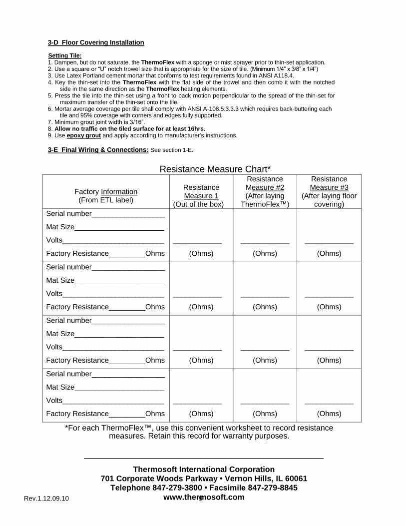
Resistance Measure Chart*
Factory Information (From ETL label)
Resistance Measure 1
(Out of the box)
Resistance Measure #2 (After laying
ThermoFlex™)
Resistance Measure #3
(After laying floor covering)
Serial number__________________
Mat Size______________________
Volts_________________________
Factory Resistance_________Ohms
____________
(Ohms)
____________
(Ohms)
____________
(Ohms)
Serial number__________________
Mat Size______________________
Volts_________________________
Factory Resistance_________Ohms
____________
(Ohms)
____________
(Ohms)
____________
(Ohms)
Serial number__________________
Mat Size______________________
Volts_________________________
Factory Resistance_________Ohms
____________
(Ohms)
____________
(Ohms)
____________
(Ohms)
Serial number__________________
Mat Size______________________
Volts_________________________
Factory Resistance_________Ohms
____________
(Ohms)
____________
(Ohms)
____________
(Ohms)
*For each ThermoFlex™, use this convenient worksheet to record resistance measures. Retain this record for warranty purposes.
Thermosoft International Corporation 701 Corporate Woods Parkway • Vernon Hills, IL 60061
Telephone 847-279-3800 • Facsimile 847-279-8845
www.thermosoft.com

Rev.1.12.09.10 10
4. Nailed –Down Wood Floors
ThermoFlex may be installed under nail-down wood floors provided the installation complies with all local and national codes, the installation steps outlined in Section 1, and the additional guidelines enumerated below. The installation methods and final approvals at the installation site are the responsibility of the Authority Having Jurisdiction.
4-A Electrical Rough-In: See section 1-A.
4-B Planning & Preparation: See section 1-B.
4-C ThermoFlex™ Installation: See section 1-C
4-D Nailed-Down Wood Floor Installation:
It is highly recommended to connect InstAlarm® during the installation to warn about accidental damage to the heating or lead wires.
1. Nails, screws or other fasteners must be installed without puncturing the heating elements, sensor wires and cold lead wires.
2. Nails or other fasteners shall not be installed closer than 0.25” from a heating element, sensor or cold lead wire.
3. In the event of inadvertent damage to the heated underlayment:
a. Call Thermosoft technical support at 800-308-8057 to discuss repair or replacement.
b. Although Thermosoft will advise and assist in repair or replacement, under no circumstances is Thermosoft responsible for damage to the ThermoFlex caused by nailing. The product warranty becomes immediately void if this occurs.
4E. Wiring & Connections: see section 1-D.

Rev.1.12.09.10 11
TROUBLE-SHOOTING
Steps for the electrician to trouble-shoot the radiant floor heating mats and programmable thermostat:
1. Turn power off at the main breaker. Check that the electrical connections are proper: 120V Power Lines connected to the 2 terminals marked LINE; heating mats connected to the 2 terminals marked LOAD (multiple mats connected in parallel: black-to-black and white-to-white); floor sensor connected to the 2 terminals marked Sensor. 2. Check to be sure all electrical connections are tight. An E2 error showing on the thermostat display screen indicates a loose sensor wire or a faulty sensor. Loose connections may also trip the GFCI. 3. Turn power on, use a Voltmeter to check the Line side of the thermostat to verify that the thermostat is receiving 120V power. If yes, proceed to Step 4. If not, trouble-shoot the power source. 4. Turn up the thermostat so that the thermostat calls for heat and the heat waves display on the thermostat display screen. If the waves appear, proceed to Step 5. If the waves do not appear, there may be a problem with the floor sensor. Check to make sure there is only one floor sensor connected to the thermostat. Connecting two sensors will prevent the thermostat from calling for heat. If two floor sensors were connected, turn off the power and disconnect one floor sensor. If only one sensor is connected, turn off the power, disconnect the sensor and measure the resistance of the floor sensor using an Ohmmeter. The resistance should be between 12 and 15 kOhms (12,000-15,000 Ohms) at 77°F to 68°F respectively. If not, call customer technical support. 5. With power on, use a voltmeter to determine if the load side of the thermostat registers 120V when the thermostat is calling for heat. If not, the thermostat may be faulty (it is not passing voltage to the mats). If the thermostat registers 120V on the load side, the thermostat is good. Proceed to Step 6 to check the heating mats.
6. Turn off power at the main breaker. Disconnect all wires and remove the thermostat. Check the
resistance between each heating mat’s white and black wires using an Ohmmeter. The resistance for each mat should be within 15% of the factory resistance recorded on the label R=N or as follows:
120V Mat Dimensions
120V Mat Resistance
Ohms
240V Mat
Dimensions
240V Mat Resistance
Ohms
1.5’ x 5’ 286±15% 1.5’ x 10’ 556±15%
1.5 x10 139±15% 1.5 x 20 274±15%
3' x 5' 129±15% 3' x 5' 519±15%
3' x 10' 64±15% 3' x 10' 253±15%
na na 3’ x 20’ 125±15%
If the mat resistance is not correct, call customer technical support. The mat heating wires may be damaged and may need to be repaired or the mat replaced. 7. To verify mats are working, with power off, connect the floor mats directly to power: 120V black-to-black (line); white-to-white (neutral); 240V black-to-black (line); red-to-red (line). 8. Turn on power to determine if the mats heat up. It may take 45 minutes or longer to feel the warm floor. Compare the warm floor to areas of the floor that are unheated to feel the difference. 9. If the mats heat up, turn off the power and replace the thermostat. If it is within the warranty period, return the thermostat for replacement. 10. If you do not determine the problem after performing the above steps, call customer technical support.
Thermosoft International Corporation 701 Corporate Woods Parkway • Vernon Hills, IL 60061
Telephone 847-279-3800 • Facsimile 847-279-8845
www.thermosoft.com

Rev.1.12.09.10 12
ThermoFlex™
RADIANT FLOOR HEATING MAT 10-YEAR LIMITED WARRANTY Thermosoft International Corporation (“Manufacturer”) warrants that its ThermoFlex™ radiant floor heating mat (“Product”) for floating laminate flooring, floating wood flooring ceramic flooring and porcelain flooring (“Applicable Flooring”) is free from defects in manufacturing, materials and workmanship in manufacture and to perform under normal use for a period of 10 years from the date the Product was originally purchased (“Limited Warranty Period”). This warranty shall not be valid under the following conditions: 1) The preparation, conditions and installation of the Product is not in accordance with industry standards as outlined by the National Wood Flooring Association for wood floor applications, and the Tile Council of America for ceramic, porcelain and natural stone applications, The National Electric Code (NEC), the Canadian Electric Code (CEC) and all applicable local electrical and building codes; 2) the installation is not conducted as per Manufacturer’s written instructions; 3) the sub-floor is not within tolerances of vapor emissions per industry standards; 4) defective hardwood planks, tile, grout, or adhesive is used in the installation; 5) subfloor cracking, settling or displacement occurs; 6) there exists a failure of floor patching or leveling materials, or use of non-approved patching or leveling materials; or 7) improper installation materials or methods are used, 8) local overheating is caused by use not in accordance with Manufacturer’s instructions, 9) the Product is not connected to the power source by a licensed electrician, 10) the owner fails to retain and supply resistance measurements recorded during installation as specified by the Manufacturer’s instructions 11) the Product’s heating elements are cut, punctured or tampered with. This limited warranty is extended to the original property developer and/or the original occupant of the property where the Product is installed (the “Owner”) and does not cover damage to the Applicable Flooring. This Limited Warranty is further subject to the exclusions and limitations provided below and on the reverse side.
TO OBTAIN WARRANTY SERVICE, FOLLOW THE INSTRUCTIONS IN STEP 4 BELOW. UPON RECEIPT OF THE DEFECTIVE PRODUCT, PAPERWORK, RECEIPT AND RESISTANCE MEASURES, MANUFACTURER WILL EXAMINE AND TEST THE PRODUCT. IF IT IS DETERMINED THAT THE PRODUCT WAS PROPERLY INSTALLED AND FAILED DURING NORMAL USE AS A RESULT OF A MANUFACTURING, DEFECT, THE MANUFACTURER WILL REMEDY THE DEFECT OR FAILURE WITHOUT CHARGE TO THE CONSUMER PROVIDED MANUFACTURER RECEIVES NOTICE OF THE WARRANTY CLAIM IN THE MANNER PROVIDED BELOW WITHIN THE LIMITED WARRANTY PERIOD. THE REMEDY FOR ANY SUCH DEFECT IS LIMITED, AT MANUFACTURER’S OPTION, TO THE REPAIR, REPLACEMENT, OR REFUND OF THE PURCHASE PRICE OF THE PRODUCT. THE WARRANTY PERIOD FOR THE REPLACEMENT PRODUCT WILL EXPIRE 10 YEARS FROM THE DATE THAT THE ORIGINAL PRODUCT WAS PURCHASED. THIS LIMITED WARRANTY DOES NOT APPLY TO THE THERMOSTATIC CONTROL UNIT WHICH IS A SEPARATELY PURCHASED COMPONENT THAT CARRIES ITS OWN WARRANTY. MANUFACTURER WARRANTS THAT THE PRODUCT PRODUCES THE RATED WATT OUTPUT LISTED ON THE LABEL WHEN OPERATED AT THE RATED VOLTAGE. MANUFACTURER MAKES NO REPRESENTATION CONCERNING THE TEMPERATURE LEVEL THAT WILL BE PRODUCED BY THE PRODUCT. MANUFACTURER ASSUMES NO LIABILITY FOR THE COST OF FLOOR COVERING MATERIALS OR THE COST TO REMOVE OR REPLACE THEM. IMPORTANT: FOR THIS WARRANTY TO BE VALID, THIS PRODUCT MUST BE CONNECTED TO A THERMOSTATIC CONTROL DEVICE WITH GROUND FAULT CIRCUIT INTERRPUPTER (GFCI) BY A LICENSED ELECTRICIAN. THIS LIMITED WARRANTY IS FURTHER SUBJECT TO THE CONDITIONS, LIMITATIONS, AND EXCLUSIONS PROVIDED ON THE REVERSE SIDE.

Rev.1.12.09.10 13
CONDITIONS/EXCLUSIONS TO THE LIMITED WARRANTY
THIS 10-YEAR LIMITED WARRANTY IS FURTHER MADE SUBJECT TO THE FOLLOWING CONDITIONS AND EXCLUSIONS, PLEASE READ THE FOLLOWING CAREFULLY: 1. Required Installation. To be covered by this Limited Warranty, the Product must be installed indoors following the Manufacturer’s recommended installation instructions for the Product and the manufacturer’s recommended installation instructions for the Applicable Flooring. This Product may only be used in “Type II” flooring applications, and is not suitable for areas exposed to constant moisture such as shower stalls, dairies, etc. This Product may not be used directly over expansion joints. 2. Limitation on Causes of Defects Covered Under Warranty. This limited warranty covers only defects in manufacturing materials or workmanship and does not cover defects, malfunctions or failures resulting from any other cause including, without limitation: (i) improper or inadequate installation; (ii) damage caused by trades people or visitors to the job site or by cutting or puncturing or other post installation damage to the heating elements; (iii) defects caused by fire, flood, tornado, hurricane, earthquake, acts of God, differential settlement, insect infestation, extraordinary environmental conditions, riot or other civil insurrections, or acts of war or conflict; (iii) defects caused by abusive conditions or accidents, such as but not limited to cutting, severe impact or abnormal vibrations; (iv) installation or use of the Product in any manner not recommended by the Manufacturer; and, (v) defects caused by improper or inadequate maintenance, cleaning, use or care of any Applicable Flooring installed over the Product, including without limitation, the use of improper or unrecommended cleaning solutions or cleaning practices. 3. Controlling Document. This warranty is the sole and exclusive description of warranties applicable to the Product. Any written or oral representation, warranties or guarantees concerning the Product which are inconsistent with or beyond the scope of the description contained herein are superceded by this document and deemed inapplicable or void. 4. Required Procedures to Submit a Warranty Claim. In order to obtain performance of any warranty obligation, the Owner must do the following: Contact the Manufacturer at the toll free number listed below or by mail at the address listed below, and request a claim form or visit www.thermosoft.com/rma/ to download the form. Complete and return the claim form along with the defective Product, Product Label showing serial number, the original dated sales receipt and a copy of the resistance measures recorded during installation to the Manufacturer by certified mail return receipt requested within the Limited Warranty Period. The phone number and address to contact the Manufacturer for these purposes is as follows:
Thermosoft International Corporation
Attention: Warranty Claim Department
701 Corporate Woods Drive
Vernon Hills, IL 60061
Phone: (847) 279-3800 Fax: (847) 279-8845 THIS LIMITED WARRANTY IS GIVEN IN LIEU OF IMPLIED WARRANTIES. IMPLIED WARRANTIES OF MERCHANTABILILITY AND FITNESS FOR PARTICULAR PURPOSE ARE DISCLAIMED. THIS WARRANTY GIVES YOU SPECIFIC LEGAL RIGHTS. YOU MAY ALSO HAVE OTHER RIGHTS THAT VARY FROM STATE TO STATE. TO THE EXTENT ALLOWED BY APPLICABLE LAWS, MANUFACTURER HEREBY DISCLAIMS ANY AND ALL SUCH RIGHTS. UNDER NO CIRCUMSTANCES SHALL MANUFACTURER BE LIABLE TO THE OWNER, OR ANY OTHER PERSON FOR ANY CONSEQUENTIAL, INCIDENTAL, ECONOMIC, DIRECT, INDIRECT, GENERAL, OR SPECIAL DAMAGES ARISING OUT OF ANY BREACH OF WARRANTY, EXPRESS OR IMPLIED, UNDER THIS CONTRACT. SOME STATES DO NOT ALLOW THE EXCLUSION OR LIMITATION OF INCIDENTAL OR CONSEQUENTIAL DAMAGES, SO THE ABOVE LIMITATION OR EXCLUSION MAY NOT APPLY TO YOU. THIS LIMITED WARRANTY HEREBY SUPERSEDES ALL PRE-EXISTING WARRANTIES, EITHER EXPRESS OR IMPLIED, RELATING TO THE PRODUCT.


![Welcome! [] Webinars/Webinar...Welcome! Webinar #17: Total Plant Cost in Thermoflex 21 Nov 2017 Agenda: * Introduction - PEACE Components in Thermoflex - Cost estimation in TFX, traditional](https://img.dokumen.tips/doc/110x75/607d21a0c20bc66fed20bca0/welcome-webinarswebinar-welcome-webinar-17-total-plant-cost-in-thermoflex.jpg)