Embed Size (px)
Citation preview

Аннотация
1
Аннотация
Company mission . . . . . . . . . . . . . . . . . . 2
Advantages and applications of thermoelectric devices . . . . . . . . . . . . 3
Principles of thermoelectricity . . . . . . . . . 5
Thermoelectric products review . . . . . . . . 7
Coolers for industrial applications . . . . . . . 9
Miniature coolers for radio-electronics . . . 18
Multistage thermoelectric coolers . . . . . . 21
Coolers for consumer devices applications 25
Special (customized) thermoelectric coolers . . . . . . . . . . . . . 26
Software for TEC application . . . . . . . . . . 27
Thermoelectric generating modules . . . . 28
Thermoelectric cooling assemblies . . . . . 32
Thermoelectric power generating sources . . . . . . . . . . . . . . . . . . . . . . . . 34
Company profile . . . . . . . . . . . . . . . . . 36
TEC installation instructions . . . . . . . . . . 39
Catalog menu

2
Company mission
KRYOTHERM was founded in 1992 basing on alarge research and development institute which had designedthermoelectric systems since the 1970’s for military and aerospace applications. From the very beginning KRYOTHERM have maintained a leading position in the world market of thermoelectric modules and devices.
Now KRYOTHERM is a world-famous company designing and manufacturing high-quality thermoelectric products. KRYOTHERM today:
— provides full modern technological production cycle, starting from raw materials;
— has an advanced R&D department;— produces a broad range of products for radio-electronics,
telecommunications, medicine, science, and many other applications;
— participates in Space and Nuclear Programs; — has more than 500 customers World Wide;— possesses vast knowledge and experience of modern
applications of thermoelectric modules; — the quality management system conforms with international
standards ISO 9001:2000.
The highest priority issues for KRYOTHERM are:— to develop and produce effective, reliable and
safe thermoelectric products;— to perform the research expected of a leading
company to ensure the ultimate perfection of our products;
— to provide the best service and full engineering support to customers;
— to meet the customer’s expectations in the most efficient way.
High quality of products, workmanship and financial stability make KRYOTHERM a reliable and beneficial partner.

3
АннотацияAdvantages and applications of thermoelectric devices
Modern laser, optical, and radio-electronic devices cannot be built without cooling and temperature control systems .
Presently companies worldwide demand compact, noiseless and reliable equipments for industrial cooling and temperature control . Thermoelectric Cooler (TEC) is a semiconductor device, based on the Peltier phenomena, that meets all of the aforementioned requirements .
Thermoelectric coolers (TEC’s) are extensively used in high-technology fields, such as telecommunications, electronics, Space, medicine and other applications. TECs are also widely used in consumer goods e.g. portable refrigerators, freezers, water coolers, compact air conditioners, etc.The use of thermoelectricity for energy Generation, for powering stand-alone objects such as remotetelecommunication, navigation, gas and oil distributingstations and corrosion protection of gas and oil pipes, offers great benefits. A thermoelectric generator allows the direct conversion of heat energy into electricity by semiconductor thermogenerating modules.
Heat pumping is one of typical TECs applications with cooling capacity ranging from milliwatts up to hundreds of watts. Exact values depend on customer requirements.TE cooling offers several distinct advantages compared to other cooling technologies:— no moving elements, no vibration;— environmental safety;— no working fluids or gases;— operation without any acoustic and electrical noise;— operation in any spatial position (zero g-sensitivity);— easy switching from cooling to heat pumping heating mode; — extremely small size (down to 2,7*2,7 mm and 1,65 mm
height) and weight;— wide variety of cooling capacity – from milliwatts up to 350 W from a single TEC; — high reliability, exceeding 300000 hours of steady-state
operation, qualified by life-tests;

4
Advantages and applications of thermoelectric devices
This catalogue includes more than 250 types of produced by KRYOTHERM thermoelectric coolers and assemblies grouped according to field of application .
— high accuracy of temperature maintaining up to 10-5 K (with an appropriate controller);
— heat pumping direction for single-stage TEC is reversible by changing the polarity of power supply;
— reliable operation in applications that are too small or too sensitive for conventional refrigeration.
Freezing is another very common TECs application. Ability to produce semiconductor materials with high merit-factor allows KRYOTHERM to serially supply single-stage TECs with ∆Tmax up to 76K. Optimized construction and materials used in multistage TEC’s allow us to achieve the best ΔT, e.g. up to 140K using 4-stage TECs. All these advantages make thermoelectric coolers highly popular, confirmed by a growing demand for a wide variety of KRYOTHERM components all over the world.

5
Аннотация
Two basic thermoelectric effects were discovered in the XIX century by European scientists. The first was Thomas Seebeck, who in 1821 discovered the phenomenon of direct conversion of heat into electric power; the second one was Jean Peltier, who discovered a solid state heat pump. In the period from 1940 through the 1950’s the Russian academic A.F. Ioffe and his colleagues synthesized semiconductor alloys, which put these effects into practice and that enabled full-scale production of thermoelectric cooling and power generating devices for wide use in various fields of human activity.
A basic thermoelectric unit is a thermocouple, which consists of p-type and n-type semiconductor elements, or pellets. Copper commutation tabs are used to interconnect pellets that are traditionally made of Bismuth Telluride-based alloy.
Principles of thermoelectricity
Usually thermocouples are combined with a module where they are connected electrically in series and thermally in parallel between two ceramic plates. Peltier phenomenon consists of the following. A contact potential difference always appears at the
point of junction of two different metals or semiconductors. If the electric current passes through them the potential difference at the junction assists or counteracts the flow. So as the current passes against the field of the potential difference the electrical source needs to expend additional energy to make the current pass through the junction and this additional energy consumption results in heat energy output at the junction. If the
field of the potential difference has the same direction as the current the field supports it and enforces the movement of the charges. This energy is drawn from the substance and as a result the temperature at the junction is reduced.So, one side of the thermoelectric module is cooled and the other is heated.
If the heat dissipation from the thermoelectric module’s hot side is provided efficiently, for example by a heatsink, the temperature of the cold side could get down to tens of degrees below the ambient temperature. In case the current changes its polarity the hot and cold sides would invert.
cold side
dielectric (ceramics)
n-type semiconductor
p-type semiconductor
hot side
conductor (copper)
6
Principles of thermoelectricity
Abbreviations and definitions
TEC Thermoelectric cooler (module)
TEE Thermoelectric element (n-type or p-type)
∆Tmax Maximum temperature difference of TEC between the hot and cold sides at junctions (∆Tmax = Thj max - Tcj min)
Imax Value of input current through TEC, that corresponds to ∆Tmax
Umax Value of input terminal voltage on TEC, that corresponds to ∆Tmax
QmaxValue of maximum cooling capacity (heat pumping) of TEC. It is determined at maximum current through a thermoelectric cooler (Imax) and at zero temperature difference between the hot and cold sides (∆T=0)
Rac Electric resistance of TEC, measured at 1 kHz alternating current
1 - thermoelectric (n-type and p-type) elements;2 – ceramic substrates;3 – thermal grease (thermal interface);4 – cold plate (cold side heat sink);5 – hot side heat-sink;6 – TEC junctions;Tcj; Thj – temperature at the cold and hot junctions of TEE.
As it is seen from the drawing the maximum temperature difference is achieved on the TEE junctions, and it decreases while moving away from them at the speed proportional to the heat resistance of the construction elements.
In this catalogue the following abbreviations and definitions are used regarding thermoelectric cooling:
Temperature gradient in the thermoelectic device

7
Thermoelectric products review
1. Industrial application TECs (high efficiency TECs, standard, two-section, round and rectangular TECs with a hole) are widely used in industrial cooling and temperature stabilization systems.
2. Coolers for radio-electronics application are used for mini and micro coolers for temperature stabilization of microchips, semiconductor lasers, different kinds of sensors and other temperature sensitive electronic components and units.
3. Multistage TECs are very useful when single-stage TECs are not able to provide the required temperature difference. Miniature size and up to 140K temperature difference determine the area of application as for deep freezing of small size electronic devices (mostly sensors and CCD matrixes for self-noise reduction). Also multistage TEСs are widely used for deepfreeze refrigerators for medicine and scientific equipment.
4. Special (customized) TECs are designed for special applications in case of specific requirements to TEC design and performance.
5. TECs for domestic application are produced in big quantities for consumer refrigeration devices (picnic boxes, mini-bars, wine cabinets, water coolers, etc.).
6. Thermoelectric Generating Modules (TGMs) generate electric power by direct conversion of heat flow into electromotive force.
7. Thermoelectric assemblies (TEAs) are cooling and heating devices, consisting of several high-density heat-exchangers bolted together with high efficient thermoelectric coolers between them. Their application allows the creation of temperature control systems with operating temperatures equal to or less than ambient temperatures with maximum coefficient of performance (COP).
8. Thermoelectric generating assemblies (TEGAs) and complete devices are stand-alone thermoelectric power sources, consisting of heat source and the heat sink bolted together with thermoelectric generating modules (TGMs) between them.
In this catalogue the following thermoelectric products are introduced:

8
Coolers for industrial applications
Designed for use in industrial systems for cooling and temperature control
Thermoelectric coolers (TEC) for industrial application provide high efficiency, reliability, and performance accuracy. Operation at temperature cycling conditions often requires rapid periodical changes of the temperatures of one or both sides of a TEC in a wide (several tens of degrees) range and a lifetime up to 500000 cycles. Thermoelectric modules and systems produced by KRYOTHERM meet all the modern industrial standards and special requirements. The quality and reliability of TECs are verified by numerous tests performed according to our advanced Quality Management System.
Applications:
General Engineering: — electronics and telecommunications equipment cooling and
thermostabilization;— thermoelectric cooling assemblies for electrical and
electronics cabinets;— high speed integrated circuits cooling;— freezers for part fixing on a worktable; — systems for temperature control over precision machining
process equipment;— equipment for active heat cycling for use in reliability testing
of microprocessors and microchips;— technological liquid coolers (exchangers) for semiconductor
industry equipment;— constant temperature baths for different technology
processes; — climatic chambers for radio electronic components testing;— cooling systems for industrial and medical lasers and their’s
power supply units.
Medicine equipment: — built-in refrigerators and conditioners for medical
equipment;— temperature controlled portable containers for storage and
transportation of biological materials; — temperature cycling systems for genetic engineering and
PCR-diagnostics; — heat exchangers for surgery;— devices for recovery and preventive therapy;— cold plates and isothermal bases for pharmacy and biology.
Measurement equipment:— gas sampling dehumidifier; — blackbody radiation standard;— dew-point sensor; — oil clouding-point tester; — heat flow probes.
Transport:— refrigerators and water coolers for cars, coaches, yachts, etc.; — local systems for driver air conditioning and climatization in
tractors and heavy trucks.
Food industry: — cooling devices for industrial production, storage and
transportation of foods;— water and beverage coolers for restaurants, bars and cafes.
KRYOTHERM’s TEC’s can operate at high temperatures, pressures, humidity and in fine vacuum.
Enviromental Safety Features:
According to RoHS directive requirements, thermoelectric coolers do not contain lead or any other forbidden materials.
KRYOTHERM produces a wide range of thermoelectric single-stage coolers that can be used for industrial applications . TEC’s that are introduced in this catalogue are able to solve most of the tasks of industrial cooling and thermo-stabilizing and are subdivided by design to high efficient, standard, one or two sections, round, square or rectangular shape ones, with or without a hole .

9
Coolers for industrial applications
High efficient single-stage TECs
Type Imax,A
Qmax,W
Umax,V
∆Tmax,K
Rac,Ohm
Dimensions, mmDesign
A B А1 В1 H
SNOWBALL-71 3,6 36,0 16,1 71 3,230,0 30,0 30,0 30,0
3,61
30,0 30,0 30,0 34,0 2STORM-71 3,6 36,0 16,1 71 3,2 40,0 40,0 40,0 40,0
1RIME-74 3,8 38,0 16,7 74 3,3
40,0 40,0 40,0 40,04,8
40,0 40,0 40,0 44,0 2
FROST-72 6,2 62,0 16,3 72 2,0540,0 40,0 40,0 40,0
3,9
140,0 40,0 40,0 44,0 2
FROST-74 6,3 65,0 16,7 74 2,0540,0 40,0 40,0 40,0 140,0 40,0 40,0 44,0 2
FROST-75 6,3 66,0 16,8 75 2,0540,0 40,0 40,0 40,0 140,0 40,0 40,0 44,0 2
ICE-71 8,0 80,0 16,1 71 1,540,0 40,0 40,0 40,0
3,4 1
40,0 40,0 40,0 44,0 2HAIL-71 8,0 80,0 16,1 71 1,5 48,0 48,0 48,0 48,0
1GLACIER- 1,5 6,1 76,0 20,1 72 2,6
40,0 40,0 40,0 40,03,9
40,0 40,0 40,0 44,0 2
GLACIER- 2,0 4,6 57,0 20,1 72 3,340,0 40,0 40,0 40,0
4,31
40,0 40,0 40,0 44,0 2
DRIFT-2,0 4,5 69,0 24,9 70 4,040,0 40,0 40,0 40,0
4,4
1
35,0 55,0 35,0 55,040,0 58,0 40,0 58,0
DRIFT-1,5 6,1 94,0 24,9 70 3,240,0 40,0 40,0 40,0
4,135,0 55,0 35,0 55,040,0 58,0 40,0 58,0
DRIFT-1,2 7,6 115,0 24,6 69 2,440,0 40,0 40,0 40,0
3,735,0 55,0 35,0 55,040,0 58,0 40,0 58,0
DRIFT-1,15 7,9 120,0 24,6 69 2,440,0 40,0 40,0 40,0
3,635,0 55,0 35,0 55,0
DRIFT-1,05 8,6 131,0 24,6 69 2,1540,0 40,0 40,0 40,0
3,535,0 55,0 35,0 55,040,0 58,0 40,0 58,0
DRIFT-0,8 11,3 172,0 24,6 69 1,6540,0 40,0 40,0 40,0
3,235,0 55,0 35,0 55,040,0 58,0 40,0 58,0
DRIFT-0,6 15,1 229,0 24,6 68 1,2540,0 40,0 40,0 40,0
3,135,0 55,0 35,0 55,040,0 58,0 40,0 58,0
CHILL 5,8 56,0 15,7 69 2,0 40,0 40,0 40,0 40,0 3,2
High efficient single-stage modules
Design 1 Design 2

10
Design 1 (A=B) Design 2
Design 3 Design 4
Coolers for industrial applications
Standard single-stage TECs
Type Imax,(Amps)
Qmax,(Watts)
Umax,(Volts)
∆Tmax,(K)
Rac,(Ohm)
Dimensions, mmDesign
A B А1 В1 H
TB-127-0,8-1,5 2,0 19,1 15,7 69 5,85 25,0 25,0 25,0 25,0 3,8
1
TB-7-1,0-2,5 1,9 1,0 0,9 70 0,33 8,0 8,0 8,0 8,0 4,8
TB-17-1,0-2,5 1,9 2,5 2,1 70 0,85 11,5 11,5 11,5 11,5 4,8
TB-31-1,0-2,5 1,9 4,5 3,9 70 1,5014,8 14,8 14,8 14,8
4,815,0 15,0 15,0 15,0
TB-63-1,0-2,5 1,9 9,1 7,9 70 3,0015,0 30,0 15,0 30,0
4,84
30,0 15,0 30,0 15,0 3
TB-71-1,0-2,5 1,9 10,2 8,9 70 3,35 23,0 23,0 23,0 23,0 4,8 1
TB-83-1,0-2,5 1,9 12,0 10,4 70 4,15 22,0 19,0 22,0 19,0 4,8 3
TB-127-1,0-2,5 1,9 18,3 15,9 70 6,2030,0 30,0 30,0 30,0
4,81
30,0 30,0 30,0 34,0 2
TB-287-1,0-2,5 1,9 40,7 35,7 69 14,00 40,0 40,0 40,0 40,0 4,8
1
TB-7-1,0-2,0 2,3 1,3 0,9 70 0,26 8,0 8,0 8,0 8,0 4,3
TB-17-1,0-2,0 2,3 3,1 2,1 70 0,65 11,5 11,5 11,5 11,5 4,3
TB-31-1,0-2,0 2,3 5,6 3,9 70 1,2514,8 14,8 14,8 14,8
4,315,0 15,0 15,0 15,0
Standard single-stage modules

11
Coolers for industrial applications
Type Imax,(Amps)
Qmax,(Watts)
Umax,(Volts)
∆Tmax,(K)
Rac,(Ohm)
Dimensions, mmDesign
A B А1 В1 H
TB-63-1,0-2,0 2,3 11,4 7,9 70 2,5015,0 30,0 15,0 30,0
4,34
30,0 15,0 30,0 15,0 3
TB-71-1,0-2,0 2,3 12,8 8,9 70 2,70 23,0 23,0 23,0 23,0 4,3 1
TB-83-1,0-2,0 2,3 14,9 10,4 70 3,20 22,0 19,0 22,0 19,0 4,3 3
TB-127-1,0-2,0 2,3 22,9 15,9 70 4,8530,0 30,0 30,0 30,0
4,31
30,0 30,0 30,0 34,0 2
TB-127-1,0-1,8 2,6 24,9 15,7 69 4,3530,0 30,0 30,0 30,0
4,11
30,0 30,0 30,0 34,0 2
TB-7-1,0-1,5 3,1 1,7 0,9 69 0,20 8,0 8,0 8,0 8,0 3,8
1TB-17-1,0-1,5 3,1 4,0 2,1 69 0,50 11,5 11,5 11,5 11,5 3,8
TB-31-1,0-1,5 3,1 7,3 3,8 69 0,9014,8 14,8 14,8 14,8
3,815,0 15,0 15,0 15,0
TB-63-1,0-1,5 3,1 14,8 7,8 69 1,8015,0 30,0 15,0 30,0
3,84
30,0 15,0 30,0 15,0 3
TB-71-1,0-1,5 3,1 16,7 8,8 69 2,05 23,0 23,0 23,0 23,0 3,8 1
TB-83-1,0-1,5 3,1 19,5 10,3 69 2,40 22,0 19,0 22,0 19,0 3,8 3
TB-127-1,0-1,5 3,1 29,9 15,7 69 3,6530,0 30,0 30,0 30,0
3,81
30,0 30,0 30,0 34,0 2
TB-287-1,0-1,5 3,1 67,8 35,7 69 8,50 40,0 40,0 40,0 40,0 3,8
1TB-7-1,0-1,3 3,6 1,9 0,9 69 0,18 8,0 8,0 8,0 8,0 3,6
TB-17-1,0-1,3 3,6 4,6 2,1 69 0,42 11,5 11,5 11,5 11,5 3,6
TB-23-1,0-1,3 3,6 6,2 2,85 69 0,6 30,0 5,0 30,0 5,0 3,1 4
TB-31-1,0-1,3 3,6 8,4 3,8 69 0,8014,8 14,8 14,8 14,8
3,6 115,0 15,0 15,0 15,0
TB-63-1,0-1,3 3,6 17,1 7,8 69 1,6015,0 30,0 15,0 30,0
3,64
30,0 15,0 30,0 15,0 3
TB-71-1,0-1,3 3,6 19,3 8,8 69 1,80 23,0 23,0 23,0 23,0 3,6 1
TB-83-1,0-1,3 3,6 22,5 10,3 69 2,20 22,0 19,0 22,0 19,0 3,6 3
TB-127-1,0-1,3 3,6 34,5 15,7 69 3,2030,0 30,0 30,0 30,0
3,61
30,0 30,0 30,0 34,0 2
TB-287-1,0-1,3 3,6 78,2 35,7 69 7,40 40,0 40,0 40,0 40,0 3,6 1
TB-63-1,0-1,15 4,0 19,3 7,8 69 1,4215,0 30,0 15,0 30,0
3,44
30,0 15,0 30,0 15,0 3
TB-32-1,0-0,8 5,8 14,1 3,9 68 0,53 40,0 6,0 40,0 6,0 3,1 3
TB-45-1,0-0,8 5,9 20,0 5,6 68 0,73 36,0 6,0 36,0 6,0 3,1 4
TB-127-1,0-0,8 5,8 56,0 15,7 69 2,0530,0 30,0 30,0 30,0
3,11
30,0 30,0 30,0 34,0 2
TB-159-1,0-0,8 5,8 69 19,6 69 3,37 32,7 41,7 32,7 41,7 3,2 4
TB-195-1,0-0,8 5,8 86,0 24,1 68 3,20 50,0 25,0 50,0 25,0 3,1 3
TB-119-1,0-0,6 7,7 70,0 14,8 68 1,48 24,0 24,5 24,0 26,5 2,15 2
TB-71-1,4-3,175 2,9 16,5 9,1 72 2,35 30,0 30,0 30,0 30,0 5,6 1
TB-127-1,4-2,9 3,2 32,3 16,3 72 3,7040,0 40,0 40,0 40,0
5,2 1
40,0 40,0 40,0 44,0 2
TB-7-1,4-2,5 3,7 2,1 0,9 72 0,18 10,0 10,0 10,0 10,0 4,91
TB-17-1,4-2,5 3,7 5,0 2,2 72 0,45 15,0 15,0 15,0 15,0 4,9To be continued on the page 12.

12
Coolers for industrial applications
Type Imax,(Amps)
Qmax,(Watts)
Umax,(Volts)
∆Tmax,(K)
Rac,(Ohm)
Dimensions, mmDesign
A B А1 В1 HTB-31-1,4-2,5 3,7 9,1 4,0 72 0,80 20,0 20,0 20,0 20,0 4,9 1
TB-48-1,4-2,5 3,6 13,5 6,0 70 1,25 35,0 20,0 35,0 20,0 4,9 3
TB-63-1,4-2,5 3,7 18,6 8,1 72 1,6020,0 40,0 20,0 40,0
4,94
40,0 20,0 40,0 20,0 3
TB-71-1,4-2,5 3,7 20,9 9,1 72 1,80 30,0 30,0 30,0 30,0 4,9 1
TB-99-1,4-2,5 3,6 27,9 12,4 70 2,45 20,040,0
40,0 20,0 40,04,9
4
20,0 40,0 20,0 3
TB-123-1,4-2,5 3,6 34,6 15,4 70 3,20 40,0 40,0 40,0 40,0 4,9 1
TB-127-1,4-2,5 3,7 37,4 16,3 72 3,2040,0 40,0 40,0 40,0
4,8 1
40,0 40,0 40,0 44,0 2
TB-63-1,4-2,0 4,6 22,2 7,9 70 1,2520,0 40,0 20,0 40,0
4,44
40,0 20,0 40,0 20,0 3
TB-127-1,4-2,0 4,6 45,0 15,9 70 2,5040,0 40,0 40,0 40,0
4,3 1
40,0 40,0 40,0 44,0 2
TB-161-1,4-2,0 4,6 57,0 20,1 70 3,3040,0 40,0 40,0 40,0
4,31
40,0 40,0 40,0 44,0 2
TB-71-1,4-1,8 5,1 27,9 8,9 70 1,28 30,0 30,0 30,0 30,0 4,2
1TB-7-1,4-1,5 6,1 3,3 0,9 69 0,11 10,0 10,0 10,0 10,0 4,0
TB-17-1,4-1,5 6,1 8,0 2,1 70 0,28 15,0 15,0 15,0 15,0 4,0
TB-31-1,4-1,5 6,1 14,6 3,9 70 0,50 20,0 20,0 20,0 20,0 4,0
TB-35-1,4-1,5 6,1 16,4 4,4 70 0,5815,0 30,0 15,0 30,0
4,04
30,0 15,0 30,0 15,0 3
TB-63-1,4-1,5 6,1 29,7 7,9 70 1,0520,0 40,0 20,0 40,0
4,04
40,0 20,0 40,0 20,0 3
TB-71-1,4-1,5 6,1 33,4 8,9 70 1,17 30,0 30,0 30,0 30,0 4,0 1
TB-99-1,4-1,5 6,1 46,0 12,4 70 1,7020,0 40,0 20,0 40,0
4,04
40,0 20,0 40,0 20,0 3
TB-123-1,4-1,5 6,1 58,0 15,4 70 2,00 40,0 40,0 40,0 40,0 4,0 1
TB-127-1,4-1,5 6,1 60,0 15,9 70 2,0540,0 40,0 40,0 40,0
3,9 1
40,0 40,0 40,0 44,0 2
TB-161-1,4-1,5 6,1 76,0 20,1 70 2,6040,0 40,0 40,0 40,0
3,91
40,0 40,0 40,0 44,0 2
ТВ-241-1,4-1,5 6,1 113,0 30,0 70 3,85 55,0 55,0 55,0 59,0 4,0 2
TB-127-1,4-1,2 7,6 75,0 15,9 70 1,5040,0 40,0 40,0 40,0
3,5 1
40,0 40,0 40,0 44,0 2
TB-7-1,4-1,15 7,9 4,2 0,9 69 0,085 10,0 10,0 10,0 10,0 3,6
1TB-17-1,4-1,15 7,9 10,2 2,1 69 0,20 15,0 15,0 15,0 15,0 3,6
TB-31-1,4-1,15 7,9 18,6 3,8 69 0,36 20,0 20,0 20,0 20,0 3,6
TB-35-1,4-1,15 7,9 21,0 4,3 69 0,4015,0 30,0 15,0 30,0
3,64
30,0 15,0 30,0 15,0 3
TB-63-1,4-1,15 7,9 37,9 7,8 69 0,7520,0 40,0 20,0 40,0
3,64
40,0 20,0 40,0 20,0 3
TB-71-1,4-1,15 7,9 43,0 8,8 69 0,80 30,0 30,0 30,0 30,0 3,6 1
TB-127-1,4-1,15 7,9 76,0 15,7 69 1,5040,0 40,0 40,0 40,0
3,4 1
40,0 40,0 40,0 44,0 2

13
Coolers for industrial applications
Type Imax,(Amps)
Qmax,(Watts)
Umax,(Volts)
∆Tmax,(K)
Rac,(Ohm)
Dimensions, mmDesign
A B А1 В1 H
TB-35-1,4-1,05 8,6 23,0 4,3 69 0,3815,0 30,0 15,0 30,0
3,44
30,0 15,0 30,0 15,0 3
TB-99-1,4-1,05 8,6 65,0 12,3 69 1,0720,0 40,0 20,0 40,0
3,44
40,0 20,0 40,0 20,0 3
TB-127-1,4-1,05 8,6 84,0 15,7 69 1,4040,0 40,0 40,0 40,0
3,3 1
40,0 40,0 40,0 44,0 2
ТВ-49-1,4-0,8 11,3 42,0 6,1 69 0,40 20,0 20,0 20,0 20,0 3,2 1
TB-99-1,4-0,8 11,3 86,0 12,3 69 0,8020,0 40,0 20,0 40,0
3,24
40,0 20,0 40,0 20,0 3
TB-7-2,0-2,5 7,6 4,2 0,9 72 0,092 14,8 14,8 14,8 14,8 4,8
1TB-17-2,0-2,5 7,6 10,2 2,2 72 0,20 22,0 22,0 22,0 22,0 4,8
TB-31-2,0-2,5 7,6 18,7 4,0 72 0,40 30,0 30,0 30,0 30,0 4,8
TB-71-2,0-2,5 7,6 43,0 9,1 72 0,87 40,0 40,0 40,0 40,0 4,8
1
TB-127-2,0-2,5 7,6 76,0 16,3 72 1,65
48,0 48,0 48,0 48,0
4,855,0 55,0 55,0 55,0
62,0 62,0 62,0 62,0
TB-127-2,0-1,65 11,3 111,0 15,9 70 1,00
48,0 48,0 48,0 48,0
4,055,0 55,0 55,0 55,0
62,0 62,0 62,0 62,0
TB-7-2,0-1,5 12,4 6,7 0,9 70 0,055 14,8 14,8 14,8 14,8 3,8
TB-17-2,0-1,5 12,4 16,3 2,1 70 0,12 22,0 22,0 22,0 22,0 3,8
1
TB-31-2,0-1,5 12,4 29,8 3,9 70 0,24 30,0 30,0 30,0 30,0 3,8
TB-71-2,0-1,5 12,4 68,0 8,9 70 0,52 40,0 40,0 40,0 40,0 3,8
TB-127-2,0-1,5 12,4 122,0 15,9 70 0,95
48,0 48,0 48,0 48,0
3,855,0 55,0 55,0 55,0
62,0 62,0 62,0 62,0
TB-111-2,0-0,8 23,1 196,0 13,7 68 0,59 35,0 40,0 35,0 40,0 3,1 4
TB-71-2,0-1,15 16,1 87,0 8,8 69 0,40 40,0 40,0 40,0 40,0 3,4
1
TB-127-2,0-1,15 16,1 156,0 15,7 69 0,75
48,0 48,0 48,0 48,0
3,455,0 55,0 55,0 55,0
62,0 62,0 62,0 62,0
TB-127-2,0-1,05 17,6 171,0 15,7 69 0,66
48,0 48,0 48,0 48,0
3,455,0 55,0 55,0 55,0
62,0 62,0 62,0 62,0
ТВ-199-2,0-0,9 20,6 310,0 24,6 69 0,87 62,0 62,0 62,0 62,0 3,2
ТВ-199-2,0-0,8 23,1 352,0 24,7 69 0,80 55,0 55,0 55,0 55,0 3,7
TB-127-2,2-1,15 19,5 189,0 15,7 69 0,58 55,0 55,0 55,0 59,0 3,5 2
TB-127-2,2-0,95 23,4 223,0 15,5 68 0,51 55,0 55,0 55,0 59,0 3,3 2
TB-31-2,8-1,5 24,4 58,0 3,9 70 0,12 40,0 40,0 40,0 40,0 4,1
1TB-32-2,8-1,5 24,4 60,0 4,0 70 0,125 40,0 40,0 40,0 40,0 4,0
TB-31-5,0-1,8 64,0 149,0 3,8 68 0,047 55,0 55,0 55,0 55,0 5,3
TB-31-5,0-1,5 77,0 178,0 3,8 68 0,039 55,0 55,0 55,0 55,0 5,0

14
Design 1* Design 2**
Design 3** Design 4**
Coolers for industrial applications
Two sections single-stage TECs
Type Sectionsconnection type Design Imax,
(Amps)Qmax,(Watts)
Umax,(Volts)
∆Tmax,(K)
Rac*,(Ohm)
Dimensions (mm)
A B H
TURBO-2,5
Serial1
1,85
36,6
31,8
70
12,2
40,0 40,0 4,8
2
Parallel 3
3,7 15,9
3,1
Separate 4 6.2++6.2
TURBO-1,5
Serial1
3,1
60,0
31,4
69
7,5
40,0 40,0 3,8
2
Parallel 3
6,2 15,7
1,85
Separate 4 3,65++3,65
TURBO-1,3
Serial1
3,6
69,0
31,4
69
6,5
40,0 40,0 3,6
2
Parallel 3
7,2 15,7
1,6
Separate 4 3,2++3,2
* — design with two lead tabs and internal serial connection of the sections;** — design with four lead tabs and sections connected in serial (design 2), in parallel (design 3) and without connection between the sections (design 4).
* — For design 4 the resistance of each separate section is indicated.
Two sections single-stage TECs
H
HOT SIDE
COLD SIDE
A
B
SECTION 1
SECTION 2

15
Coolers for industrial applications
Design 1 Design 2
Round shape single-stage TECs
Type Imax,(Amps)
Qmax,(Watts)
Umax,(Volts)
∆Tmax,(K)
Rac,(Ohm)
Dimensions, mmDesign
D d HTB-21-1,0-1,3CHR 3,6 5,7 2,6 69 0,52 15,0 3,0 3,6
1
TB-38-1,0-0,8CHR 5,8 16,8 4,7 69 0,64 24,0 9,8 3,1TB-38-1,0-1,3CHR 3,6 10,3 4,7 69 1,00 24,0 9,8 3,6TB-38-1,0-1,5CHR 3,1 8,9 4,7 69 1,12 24,0 9,8 3,8TB-43-1,0-0,8CHR 5,8 19,0 5,3 69 0,70 24,0 5,0 3,1TB-253-1,4-1,5 R 6,1 119,0 31,7 70 4,30 62,0 – 3,9 2
Rectangular shape single-stage TECs with a hole
Type Imax,(Amps)
Qmax,(Watts)
Umax,(Volts)
∆Tmax,(K)
Rac,(Ohm)
Dimensions, mmA B H d
TB-41-1,0-0,8CH 5,8 18,1 5,1 68 0,67 22,5 17,5 3,1 9,5TB-41-1,0-1,3CH 3,6 11,2 5,1 69 1,10 22,5 17,5 3,6 9,5TB-41-1,0-1,5CH 3,1 9,6 5,1 69 1,20 20,0 20,0 3,8 6,5
TB-119-1,0-1,3CH 3,6 32,3 14,7 69 3,10 30,0 30,0 3,6 4,0TB-119-1,0-1,5CH 3,1 28,0 14,7 69 3,40 30,0 30,0 3,8 4,0TB-119-1,0-2,0CH 2,3 21,0 14,7 69 4,90 30,0 30,0 4,3 4,0TB-41-1,4-1,1CH 8,3 25,9 5,1 69 0,45 23,0 23,0 3,5 9,5
TB-109-1,4-1,5СН 6,1 51,0 13,7 70 1,80 40,0 40,0 4,0 13,0TB-119-1,4-1,15CH 7,9 72,0 14,7 69 1,40 40,0 40,0 3,6 7,8TB-119-1,4-1,5CH 6,1 56,0 14,9 70 1,90 40,0 40,0 4,0 7,8TB-119-1,4-2,5CH 3,7 35,1 15,3 72 3,00 40,0 40,0 4,9 7,8
TB-125-1,4-1,15CH 7,9 75,0 15,5 69 1,50 40,0 40,0 3,6 4,7TB-125-1,4-1,5CH 6,1 59,0 15,7 70 2,00 40,0 40,0 4,0 4,7TB-125-1,4-2,5CH 3,7 36,8 16,0 72 3,10 40,0 40,0 4,9 4,7
Standard single-stage round shape modules
Rectangular single-stage modules with hole

16
Coolers for industrial applications
Additional options
Description Notation (*) NoteSubstrates material
Alumina Al2O3 (ВК-96) - Standard performance
Aluminium nitride (AlN) N Heat conductivity> 180 W/mK
Operating and mounting temperaturesOperating temperature up to 80°С (standard);Mounting temperature ≤ 130 °C**
- Standard performance.Melting point of TEC’s solder T=139°C
Operating temperature up to 120 °C, max Mounting temperature ≤ 130 °C** HT(120) Melting point of TEC’s
solder T=139°C
Operating temperature up to 150 °C, max Mounting temperature ≤ 170 °C** HT(150)*** Melting point of TEC’s
solder T=183°C (Pb-Sn)***
Operating temperature up to 200 °C, max Mounting temperature ≤ 220 °C** HT(200) Melting point of TEC’s
solder T= 232 °C
Parallelism and flatness of mounting surfacesFlatness 0,02 mm;Parallelism 0,03 mm L1 Standard performance.
Height tolerance ± 0,05 mm
Flatness 0,015 mm; Parallelism 0,02 mm L2 Height tolerance ± 0,025mm
Flatness 0,01 mm;Parallelism 0,01 mm L3 Height tolerance ± 0,015mm
Metallization of cold and (or) hot sidesMetallization of cold (mc) and (or) hot side of TEC
mc95, mh95,mm117 etc.
Solder tinning (melting temperatures 95 °C, 117 °C, 139 °C or 183 °C)
Gold plating mcAu, mhAu, mmAu 0,2-1 micron thickness
Nickel plating mcNi, mhNi, mmNi
Other standard and additional optionsSealants: epoxy, silicon, urethane, conformal coating E, S, U, Сс
Special performance for operation under conditions of temperature cycling С Standard performance.
> 105 cycles +40°C /+90°C
Tolerance of Rac value ±10% for Rac>0,15 Ohm± 15% for Rac≤ 0,15 Ohm
Tolerance of length (dimensions А, А1) and width (dimensions В, В1) or external diameter (dimension D)
+0,5/–0,2mm
Tolerance of internal diameter (dimension d for TECs with hole) +0,2/–0,5mm
Lead tabs orientation for rectangular TECs - On the long side - standard
Type and length of lead wires (standard length 120 mm)
-
By customer’s requirementsAssembling into arrays -
Connectors attachment -
TEC could be mounted on heatsink, cold block or into a case
-
(*) - the notations shown are used to notate additional options in TECs name (please refer to System of Notation section below);(**) - the maximum mounting temperature influence on the module must not exceed 2 minutes;(***) - attention! This option does not meet ROHS requirements.

17
System of notation:A universal abbreviation is used to notate single-stage TECs: ТВ-N-C-h, where:
ТВ — product abbreviation — thermoelectric battery (TEC);N — number of thermocouples in the TEC;С — length of the edge of the thermoelectric element basis (in millimeters);h — height of the thermoelectric element (in millimeters).
For example: TB-161-1,4-1,5 consists of 161 thermocouples (322 thermoelectric elements), every element has the cross-section of 1,4x1,4 mm and is 1,5 mm high.
Additional index ВВ in abbreviation (ТВ-N-C-h-BB) is used only for TECs with hole or/and for TECs of round shape:CH — for rectangular TEC with a central hole (for example ТВ-43-1,0-0,8CH);CHR — for round TECs with a central hole (for example ТВ-19-1,0-1,3CHR);R — for round TECs (for example TB-253-1,4-1,5R).
Each type of high efficient and two-section TECs has additional individual name. Two-section TECs with four lead tabs also have abbreviations indicating number of thermocouples in the first and the second sections.
Examples:1. FROST-72 HT(150) means thermoelectric cooler FROST-72, with max operating temperature of 150°С, with substrate material of
aluminum oxide (alumina).
2. DRIFT-0,8 HT(200) mmAu N means thermoelectric cooler DRIFT-0,8 with max operating temperature 200°С, with substrate material of aluminum nitride. Cold and hot surfaces are coated with gold.
Enviromental Safety Features:The thermoelectric coolers do not contain lead or any other forbidden materials according to RoHS directive requirements.
Coolers for industrial applications

18
Miniature coolers for radio-electronics
Miniature coolers for radio-electronics
Type Imax,(Amps)
Qmax,(Watts)
Umax,(Volts)
∆Tmax,(K)
Rac,(Ohm)
Dimensions, mmDesign
A B А1 В1 HTB-8-0,45-1,3 0,7 0,4 1,0 67 1,20 3,4 3,4 5,0 3,4 2,3
1
TB-12-0,45-1,3 0,7 0,6 1,4 67 1,80 3,4 5,0 5,0 5,0 2,3
TB-18-0,45-1,3 0,7 0,9 2,2 67 2,80 5,0 5,0 6,6 5,0 2,3
TB-32-0,45-1,3 0,7 1,7 3,9 67 5,00 6,6 6,6 8,3 6,6 2,3
TB-66-0,45-1,3 0,7 3,5 8,0 67 10,0 9,1 9,9 11,5 9,1 2,3
TB-7-0,6-1,5 1,1 0,6 0,9 69 0,59 4,3 4,3 4,3 4,3 3,25 2
TB-11-0,6-1,5 1,1 0,9 1,4 69 0,91 9,0 4,0 9,0 4,0 3,25 3
TB-17-0,6-1,5 1,1 1,4 2,1 69 1,50 6,3 6,3 6,3 6,3 3,252
TB-31-0,6-1,5 1,1 2,6 3,8 69 2,65 8,0 8,0 8,0 8,0 3,25
TB-35-0,6-1,5 1,1 3,0 4,3 69 3,106,0 12,0 6,0 12,0
3,254
12,0 6,0 12,0 6,03
TB-65-0,6-1,5 1,1 5,5 8,1 69 5,60 13,0 12,0 13,0 12,0 3,25
Design 1 Design 2
Design 3 Design 4
H
HOT SIDE
COLD SIDE
B=B1
A=A1
Miniature thermoelectric coolers (TECs) are used for direct cooling (and freezing) and temperature stabilization of small size temperature-sensitive electronic components and devices . Such TECs could be installed into vacuum-processed cases .
Coolers could be directly integrated into the standard devices e .g . ТО (ТО3, ТО8 etc), HHL, DIL, Butterfly or any other special enclosures .
Applications:— input stages of low-noise amplifiers and receivers;— optical communication laser diode;— interferometer laser diode;— microprocessors and critical microchips;— PCBs and electronic units;— infrared detectors;— CCD- matrix, incl. night vision equipment;— photomultipliers, photodetectors and other
temperature sensitive elements and components of electronic devices.

19
Miniature coolers for radio-electronics
Type Imax,(Amps)
Qmax,(Watts)
Umax,(Volts)
∆Tmax,(K)
Rac,(Ohm)
Dimensions, mmDesign
A B А1 В1 HTB-7-0,6-1,2 1,4 0,7 0,9 69 0,51 4,3 4,3 4,3 4,3 2,95 2
TB-11-0,6-1,2 1,4 1,2 1,4 69 0,75 4,0 9,0 4,0 9,0 2,95 4
TB-17-0,6-1,2 1,4 1,8 2,1 69 1,20 6,3 6,3 6,3 6,3 2,952
TB-31-0,6-1,2 1,4 3,3 3,8 69 2,05 8,0 8,0 8,0 8,0 2,95
TB-35-0,6-1,2 1,4 3,7 4,3 69 2,406,0 12,0 6,0 12,0
2,954
12,0 6,0 12,0 6,0 3
TB-65-0,6-1,2 1,4 6,9 8,1 69 4,60 13,0 12,0 13,0 12,0 2,95 3
TB-7-0,6-1,0 1,7 0,9 0,9 69 0,39 4,3 4,3 4,3 4,3 2,75 2
TB-17-0,6-1,0 1,7 2,2 2,1 69 0,95 6,3 6,3 6,3 6,3 2,752
TB-31-0,6-1,0 1,7 3,9 3,8 69 1,70 8,0 8,0 8,0 8,0 2,75
TB-35-0,6-1,0 1,7 4,4 4,3 69 2,086,0 12,0 6,0 12,0
2,754
12,0 6,0 12,0 6,03
TB-65-0,6-1,0 1,7 8,3 8,1 69 4,00 13,0 12,0 13,0 12,0 2,75
TB-7-0,6-0,8 2,1 1,1 0,9 68 0,34 4,3 4,3 4,3 4,3 2,552
TB-17-0,6-0,8 2,1 2,6 2,1 68 0,76 6,3 6,3 6,3 6,3 2,55
TB-23-0,6-0,8 2,1 3,6 2,8 68 1,45 6,0 8,5 6,0 10,5 1,95 1
TB-31-0,6-0,8 2,1 4,8 3,8 68 1,40 8,0 8,0 8,0 8,0 2,55 2
TB-35-0,6-0,8 2,1 5,4 4,3 68 1,706,0 12,0 6,0 12,0
2,554
12,0 6,0 12,0 6,03
TB-65-0,6-0,8 2,1 10,1 8,0 68 3,00 13,0 12,0 13,0 12,0 2,55
TB-109-0,6-0,8 2,1 16,9 13,4 68 5,00 12,0 26,0 12,0 26,0 2,55 4
TB-17-1,0-0,7 6,6 8,4 2,1 68 0,24 8,0 8,0 8,0 8,0 2,45 2
Standard and additional options for single-stage miniature coolers
Description Notation (*) NoteSubstrates material
Alumina Al2O3 (ВК-96) - Standard performance
Aluminium nitride (AlN) N Heat conductivity> 180 W/m.K
Operating and mounting temperaturesOperating temperature up to 120 °C (standard), max Mounting temperature ≤ 130 °C** HT(120) Standard performance.
Melting point of TEC’s solder T=139°C
Operating temperature up to 150 °C, max Mounting temperature ≤ 170 °C** HT(150)*** Melting point of TEC’s
solder T=183°C (Pb-Sn)***
Operating temperature up to 200 °C, max Mounting temperature ≤ 220 °C** HT(200) Melting point of TEC’s
solder T= 232 °C
Parallelism and flatness of mounting surfaces
Flatness 0,10 mm; Parallelism 0,15 mm L0 Standard performance. Height tolerance ± 0,15 mm
Flatness 0,02 mm; Parallelism 0,03 mm L1 Height tolerance ± 0,05mm
Flatness 0,015 mm; Parallelism 0,02 mm L2 Height tolerance ± 0,015mm
To be continued on the page 20.
20
Miniature coolers for radio-electronics
Metallization of cold and (or) hot sidesMetallization of cold (mc) and (or) hot side of TEC with solder tinning
mc95, mh95,mm117 etc.
Melting temperatures 95 °C, 117 °C, 139 °C or 183 °C
Gold plating mcAu, mhAu, mmAu 0,2-1 micron thickness
Other standard and additional optionsSealants: epoxy, silicon, urethane, conformal coating E, S, U, Сс Standard performance is without sealant
Tolerance of Rac value of :TEE with length of the edge>0,45 mmTEE with length of the edge ≤ 0,45 mm
±10% ±15%
Tolerance of length (dimensions А, А1) and width (dimensions В, В1) +0,5/–0,2mm
Type and length of wires (standard length 50 mm)
-
Up to customer’s requirementsTEC could be mounted into electronic enclosures e.g. ТО, HHL, DIL, Butterfly, etc.
-
Assembling into arrays
Connectors attachment
(*) - the notations shown are used to notate additional options in TEC’s name (please refer to System of Notation section below);(**) - the maximum mounting temperature influence on the TEC must not exceed 2 minutes;(***) - attention! This option does not meet ROHS requirements.
System of notation:A universal abbreviation is used to notate single-stage miniature TECs: ТВ-N-C-h, where:
ТВ — product abbreviation — thermoelectric battery (TEC);N — number of thermocouples in the TEC;С — length of the edge of the thermoelectric element basis (in millimeters);h — height of the thermoelectric element (in millimeters).
For example: TB-109-0,6-0,8 HT(200) mmAu N denotes: thermoelectric battery (TEC), composed of 109 thermocouples (218 thermoelectric elements), each element has the cross-section of 0,6×0,6 mm and is of 0,8 mm high, ceramics plates material is aluminium nitride. TEC can operate at temperatures up to 200°C, both ceramic plates have golden coating.
Enviromental Safety Features:The thermoelectric coolers do not contain lead or any other forbidden material according to RoHS directive requirements.
21
Multistage thermoelectric coolers
Design 1 Design 2 Design 3 Design 4
Two stage TEC
Two stage thermoelectric coolers
Type Imax,(Amps)
Qmax,(Watts)
Umax,(Volts)
∆Tmax,(K)
Rac,(Ohm)
Dimensions, mmDesign
A B А1 В1 HTB-2-(11-4)-1,5 1,0 0,4 1,3 93 1,26 6,0 4,0 4,0 2,0 6,7
3TB-2-(11-4)-1,2 1,2 0,5 1,3 92 1,55 6,0 4,0 4,0 2,0 6,1
TB-2-(11-4)-1,0 1,5 0,6 1,3 92 0,85 6,0 4,0 4,0 2,0 5,7
TB-2-(17-4)-1,5 1,1 0,4 2,0 94 1,85 6,0 8,0 2,0 4,0 6,7
4
TB-2-(17-4)-1,2 1,3 0,5 2,0 93 1,50 6,0 8,0 2,0 4,0 6,1
TB-2-(17-4)-1,0 1,6 0,6 2,0 91 1,26 6,0 8,0 2,0 4,0 5,7
TB-2-(31-8)-1,5 1,1 0,9 3,6 93 3,40 8,0 10,0 4,0 4,0 6,7
TB-2-(31-8)-1,2 1,3 1,1 3,6 92 2,70 8,0 10,0 4,0 4,0 6,1
TB-2-(31-8)-1,0 1,6 1,3 3,6 91 2,25 8,0 10,0 4,0 4,0 5,7
TB-2-(31-12)-1,5 1,0 1,1 3,7 93 3,60 8,0 10,0 4,0 6,0 6,7
TB-2-(31-12)-1,2 1,2 1,4 3,7 92 2,85 8,0 10,0 4,0 6,0 6,1
To be continued on the page 22.
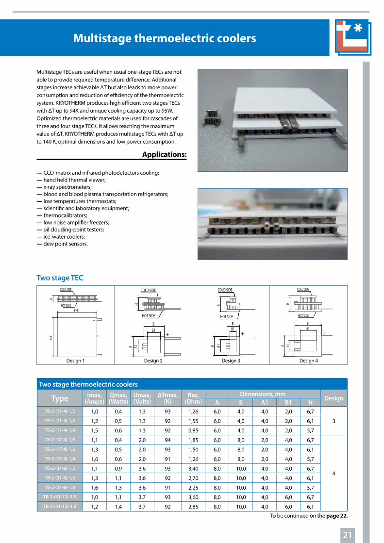
Multistage TECs are useful when usual one-stage TECs are not able to provide required temperature difference. Additional stages increase achievable ΔТ but also leads to more power consumption and reduction of efficiency of the thermoelectric system. KRYOTHERM produces high efficient two stages TECs with ΔТ up to 94K and unique cooling capacity up to 95W. Optimized thermoelectric materials are used for cascades of three and four stage TECs. It allows reaching the maximum value of ΔТ. KRYOTHERM produces multistage TECs with ΔТ up to 140 К, optimal dimensions and low power consumption.
Applications:
— CCD-matrix and infrared photodetectors cooling;— hand held thermal viewer;— x-ray spectrometers;— blood and blood plasma transportation refrigerators;— low temperatures thermostats;— scientific and laboratory equipment;— thermocalibrators;— low noise amplifier freezers;— oil clouding-point testers;— ice-water coolers;— dew point sensors.

22
Multistage thermoelectric coolers
Type Imax,(Amps)
Qmax,(Watts)
Umax,(Volts)
∆Tmax,(K)
Rac,(Ohm)
Dimensions, mmDesign
A B А1 В1 HTB-2-(31-12)-1,0 1,4 1,6 3,7 91 2,40 8,0 10,0 4,0 6,0 5,7 4
TB-2-(59-18)-1,5 1,1 1,8 7,1 94 6,70 12,0 12,0 6,0 6,0 6,7
2TB-2-(59-18)-1,2 1,3 2,2 7,1 93 5,30 12,0 12,0 6,0 6,0 6,1
TB-2-(59-18)-1,0 1,5 2,6 7,0 92 4,35 12,0 12,0 6,0 6,0 5,7
TB-2-(127-127)-1,3 2,8 16,1 15,4 83 4,70 30,0 30,0 30,0 30,0 8,8
1
TB-2-(127-127)-1,15 5,8 34,0 15,4 84 2,30 40,0 40,0 40,0 40,0 8,5
TB-2-(127-127)-1,158,8 31,0 8,9 87 1,05 40,0 40,0 40,0 40,0 7,5
(BULLFINCH)
TB-2-(199-199)-0,8 10,2 95,0 24,0 84 2,30 40,0 40,0 40,0 40,0 6,8
Three stage TECs
Design 1 (A=B) Design 2 Design 3
Three stage thermoelectric coolers
Type Imax,(Amps)
Qmax,(Watts)
Umax,(Volts)
∆Tmax,(K)
Rac,(Ohm)
Dimensions, mmDesign
A B А1 В1 HTB-3-(31-11-4)-1,5 0,9 0,4 3,5 109 5,40 8,0 10,0 2,0 4,0 9,3
3TB-3-(31-11-4)-1,2 1,1 0,5 3,5 108 4,30 8,0 10,0 2,0 4,0 8,4
TB-3-(31-11-4)-1,0 1,3 0,6 3,5 107 3,60 8,0 10,0 2,0 4,0 7,8
TB-3-(49-17-4)-2,5 6,3 3,3 5,3 113 0.9 36,0 36,0 8,0 14,0 16,0
TB-3-(59-17-4)-1,5 1,0 0,5 6,8 114 7,20 12,0 12,0 2,0 4,0 9,3
1TB-3-(59-17-4)-1,2 1,2 0,6 6,8 113 5,80 12,0 12,0 2,0 4,0 8,4
TB-3-(59-17-4)-1,0 1,4 0,7 6,8 112 4,80 12,0 12,0 2,0 4,0 7,8
TB-3-(83-18-4)-1,3 3,7 2,5 10,0 118 2,35 24,0 20,6 8,7 4,5 10,8 2

23
Multistage thermoelectric coolers
Four stage thermoelectric coolers
Type Imax,(Amps)
Qmax,(Watts)
Umax,(Volts)
∆Tmax,(K)
Rac,(Ohm)
Dimensions, mmDesign
A B А1 В1 HTB-4-(59-31-11-4)-1,5 0,8 0,4 6,9 118 8,90 12,0 12,0 2,0 4,0 12,2
1TB-4-(59-31-11-4)-1,2 1,0 0,5 6,9 117 7,15 12,0 12,0 2,0 4,0 11,0
TB-4-(59-31-11-4)-1,0 1,1 0,6 6,9 116 5,95 12,0 12,0 2,0 4,0 10,2
TB-4-(83-18-4-1)-1,3 3,7 0,8 10,0 138 2,37 24,0 20,6 4,5 2,4 13,6 2
TB-4-(127-71-31-17)-1,65 6,8 14,8 14,1 107 2,05 48,0 48,0 22,0 22,0 15,01
TB-4-(199-97-49-17)-1,5 6,7 16,9 23,6 111 3,45 62,0 62,0 20,0 20,0 14,5
Four stage TECs
Standard and additional options for single-stage miniature coolers
Description Notation (*) NoteSubstrates material
Alumina Al2O3 (ВК-96) - Standard performance
Aluminium nitride (AlN) N Heat conductivity> 180 W/m.K
Operating and mounting temperaturesOperating temperature up to 120 °C (standard), max Mounting temperature ≤ 130 °C** HT(120) Standard performance.
Melting point of TEC’s solder T=139°C
Operating temperature up to 150 °C, max Mounting temperature ≤ 170 °C** HT(150)*** Melting point of TEC’s
solder T=183°C (Pb-Sn)***
To be continued on the page 24.
Design 1
Design 2

24
Multistage thermoelectric coolers
Parallelism and flatness of mounting surfacesFlatness 0,1 mm;Parallelism 0,15 mm L4 Standard performance.
Height tolerance ± 0,35 mm
Flatness 0,02 mm; Parallelism 0,03 mm L1**** Height tolerance ± 0,05mm
Flatness 0,015 mm;Parallelism 0,02 mm L2**** Height tolerance ± 0,025mm
Metallization of cold and (or) hot sidesMetallization of cold (mc) and (or) hot side of TEC with solder tinning
mc95, mh95,mm117 etc.
Melting temperatures 95 °C, 117 °C, 139 °C or 183 °C
Gold plating mcAu, mhAu, mmAu 0,2-1 micron thickness
Nickel plating mcNi, mhNi, mmNi
Other standard and additional optionsSealants: epoxy, silicon, urethane, conformal coating Сс
Tolerance of Rac value ± 15%
Tolerance of length (dimensions А, А1) and width (dimensions В, В1) +0,5/–0,2mm
Tolerance of height ±0,35mm (standart performance)
Type and length of lead wires (standard length 120 mm)
-
Up to customer’s requirementsConnectors attachment -
TEC could be mounted on heatsink, cold block or into the electronic devices enclosure
-
(*) – the notations shown are used to notate additional options in the cooler name (please refer to System of Notation below);(**) – the maximum mounting temperature influence on the TEC must not exceed 2 minutes;(***) – attention! This option does not meet ROHS requirements;(****) – to be agreed.
System of notation:A universal abbreviation is used to notate multistage TECs: ТВ-n-(N1-N2-N3-N4)-h, where:
ТВ — product abbreviation — thermoelectric battery (TEC);n — number of stages in the TEC;N — number of thermocouples in the TEC:(N1-N2) is used for two stage TECs; (N1-N2-N3) — for three stage TECs;(N1-N2-N3-N4) — for four stage TECs;h — height of the thermoelectric element of the bottom stage (in millimeters).
For example: TB-2-(11-4)-1,0 HT (200) mmAu N denotes a two-stage thermoelectric cooler with max operating temperature 200°C, that consists of 11 thermocouples (22 thermoelectric elements) in the base stage and 4 thermocouples in the second stage, every element has the cross-section of 1x1 mm. The TEC is made on a aluminium nitride substrate. Cold and hot sides are metallized with golden coating.
Enviroment safety features:The thermoelectric coolers do not contain lead or any other forbidden materials according to RoHS directive requirements.

25
Coolers for consumer devices applications
Standard and additional options for LCB TECs
Description Notation (*) NoteSubstrates material
Alumina Al2O3 (ВК-96) - -
Operating and mounting temperatures
Operating temperature up to 120 °C, (standard)max Mounting temperature ≤ 130 °C** HT(120) Standard performance.
Melting point of TEC’s solder T=139°C
Operating temperature up to 150 °C, max Mounting temperature ≤ 170 °C** HT(150)*** Melting point of TEC’s
solder T=183°C (Pb-Sn)***
Operating temperature up to 200 °C, max Mounting temperature ≤ 220 °C** HT(200) Melting point of TEC’s
solder T= 232 °C
LCB TECs
High-performance equipment application and fine-tuned technological process allow KRYOTHERM to produce the modules listed below in unlimited quantities using a non-stop technological process providing high reliability and low costs .
To be continued on the page 26.
Deliveries of TECs in quantities more than 100000 per month could be fulfilled with further production volume growing up to the customer required level.
Main fields of application:
— portable automobile refrigerators and picnic boxes;— beverages and water coolers;— mini-refrigerators and mini-bars;— cold-plates for the kitchen;— personal air conditioning units;— wine cabinets and beer coolers;— mini refrigerators for cosmetics.
Coolers for consumer devices applications
Type Imax,Amps
Qmax,Watts
Umax,Volts
∆Tmax,K
Rac,Ohm
Dimensions (mm)
A B HLCВ-127-1,0-1,3 3,6 36,0 16,1 71 3,20 30,0 30,0 3,6
LCВ-127-1,4-1,5 6,1 61,0 16,1 71 2,05 40,0 40,0 3,9
LCB-127-1,4-1,15 8,0 80,0 16,1 71 1,5 40,0 40,0 3,4
LCB-127-1 .0-0,8 5,8 56,0 15,7 69 2,0 40,0 40,0 3,2
LCВ-127-1,4-2,5 3,7 37,4 16,3 72 3,2 40,0 40,0 4,8
26
Coolers for consumer devices applications
(*) - the notations shown are used to notate additional options in TECs name (please refer to System of Notation section below); (**) - the maximum mounting temperature influence on the module must not exceed 2 minutes; (***) - attention! This option does not meet ROHS requirements.
Parallelism and flatness of mounting surfacesFlatness 0,02 mm; Parallelism 0,03 mm L1 Standard performance.
Height tolerance ± 0,05mm
Other standard and additional optionsSealants: epoxy, silicon, urethane, conformal coating E, S, U, Cc
Tolerance of Rac value ± 10%
Tolerance of length (dimensions А, А1) and width (dimensions В, В1) +0,5/–0,2mm
Tolerance of height ±0,05mm (standart performance)
Type and length of wires (standard length 120 mm) - HB (polyvinylchloride insulation)
System of notation:A universal abbreviation is used to notate LCB TECs: LCB-N-C-h, where:
LCB — product abbreviation — low-cost thermoelectric battery for mass consumption; N — number of thermocouples in the cooler; С — length of the edge of the thermoelectric element basis (in millimeters); h — height of the thermoelectric element (in millimeters).
For example: LCB-127-1,0-1,3 consists of 127 thermocouples (254 thermoelectric elements), every element has the cross-section of 1,0x1,0 mm and is 1,3 mm high.
Enviromental Safety Features:The thermoelectric coolers do not contain lead or any other forbidden materials according to RoHS directive requirements.
High performance of LCB type thermoelectric coolers, produced by KRYOTHERM allows customers to increase the rate of cooling capacity and obtain larger temperature difference at the same environmental conditions. Thermoelectric coolers are optimized for 12V power source and perform high cooling power at low power consumption.
Special (customized) thermoelectric coolers
Manufacturing of such TECs besides the standard technological process usually requires additional production steps, including additional quality control of special parameters. Special properties could be also obtained by using materials with special parameters (special thermoelectric materials, ceramic substrates, solder and others).
To provide high precision temperature control temperature sensors could be integrated inside of TEC on cold and/or hot junctions. All these allow KRYOTHERM to guarantee customized requirements.
Special requirements examples:— high vacuum application (<10-6);— improved mechanical (shocks and vibrations) resistance; — low TECs height (less than 1,5 mm);— higher cooling rate >10 K/sec; — higher cooling power density >20 W/cm2; — lower temperatures operation (<-55°C);— higher precision temperature control;— flux free soldering;— operation at hard temperature cycling conditions.
Fields of applications:— Space and other special techniques;— optoelectronics and telecommunications;— medicine;— special computers engineering;— scientific apparatus.
Depending on customer operation conditions KRYOTHERM offers additional options and structural features for TECs with special properties and design .
27
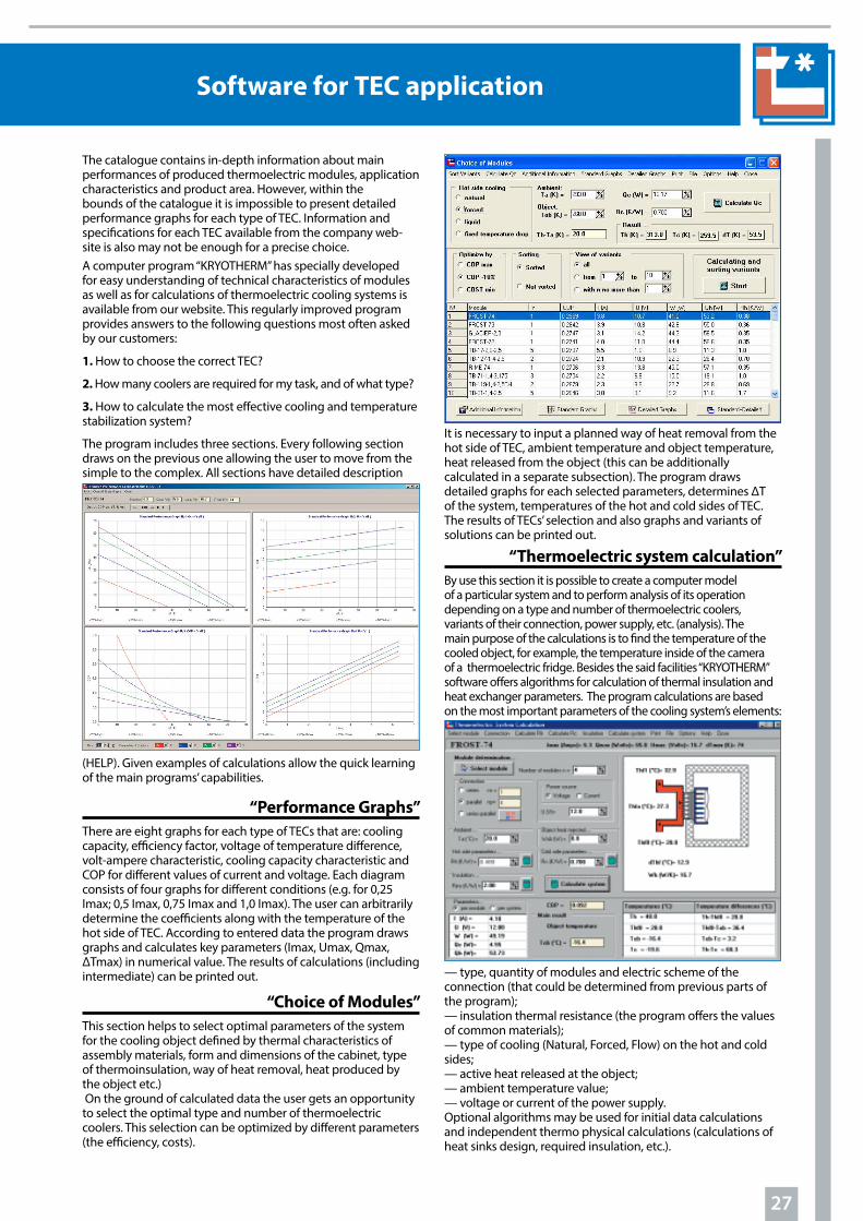
It is necessary to input a planned way of heat removal from the hot side of TEC, ambient temperature and object temperature, heat released from the object (this can be additionally calculated in a separate subsection). The program draws detailed graphs for each selected parameters, determines ∆T of the system, temperatures of the hot and cold sides of TEC. The results of TECs’ selection and also graphs and variants of solutions can be printed out.
“Thermoelectric system calculation” By use this section it is possible to create a computer model of a particular system and to perform analysis of its operation depending on a type and number of thermoelectric coolers, variants of their connection, power supply, etc. (analysis). The main purpose of the calculations is to find the temperature of the cooled object, for example, the temperature inside of the camera of a thermoelectric fridge. Besides the said facilities “KRYOTHERM” software offers algorithms for calculation of thermal insulation and heat exchanger parameters. The program calculations are based on the most important parameters of the cooling system’s elements:
— type, quantity of modules and electric scheme of the connection (that could be determined from previous parts of the program); — insulation thermal resistance (the program offers the values of common materials); — type of cooling (Natural, Forced, Flow) on the hot and cold sides;— active heat released at the object;— ambient temperature value;— voltage or current of the power supply. Optional algorithms may be used for initial data calculations and independent thermo physical calculations (calculations of heat sinks design, required insulation, etc.).
The catalogue contains in-depth information about main performances of produced thermoelectric modules, application characteristics and product area. However, within the bounds of the catalogue it is impossible to present detailed performance graphs for each type of TEC. Information and specifications for each TEC available from the company web-site is also may not be enough for a precise choice. A computer program “KRYOTHERM” has specially developed for easy understanding of technical characteristics of modules as well as for calculations of thermoelectric cooling systems is available from our website. This regularly improved program provides answers to the following questions most often asked by our customers:
1. How to choose the correct TEC?
2. How many coolers are required for my task, and of what type?
3. How to calculate the most effective cooling and temperature stabilization system?
The program includes three sections. Every following section draws on the previous one allowing the user to move from the simple to the complex. All sections have detailed description
(HELP). Given examples of calculations allow the quick learning of the main programs’ capabilities.
“Performance Graphs” There are eight graphs for each type of TECs that are: cooling capacity, efficiency factor, voltage of temperature difference, volt-ampere characteristic, cooling capacity characteristic and СОР for different values of current and voltage. Each diagram consists of four graphs for different conditions (e.g. for 0,25 Imax; 0,5 Imax, 0,75 Imax and 1,0 Imax). The user can arbitrarily determine the coefficients along with the temperature of the hot side of TEC. According to entered data the program draws graphs and calculates key parameters (Imax, Umax, Qmax, ∆Tmax) in numerical value. The results of calculations (including intermediate) can be printed out.
“Choice of Modules”This section helps to select optimal parameters of the system for the cooling object defined by thermal characteristics of assembly materials, form and dimensions of the cabinet, type of thermoinsulation, way of heat removal, heat produced by the object etc.) On the ground of calculated data the user gets an opportunity to select the optimal type and number of thermoelectric coolers. This selection can be optimized by different parameters (the efficiency, costs).
Software for TEC application

28
Thermoelectric Generating modules
Thermoelectric Generating Module drawing and structure
cold side
dielectric (ceramics)
n-type semiconductor
p-type semiconductor
hot side
conductor
With thermoelectric generating modules (TGM), produced by KRYOTHERM, is possible to get up to several watts DC with voltage up to 6V from one TGM at a temperature difference between it’s hot and cold sides of 100°С .
Applications:
— utilization of waste heat from vehicles (automobiles,
ships) engines;
— autonomic supply of energy to operation control
devices of water boilers and disposal plants;
— cathodic protection of the oil and gas pipelines;
— conversion of natural heat resources — geothermal
waters, etc. into electric energy;
— power supply of stand-alone low-power electronic
devices (Energy Harvesting).

29
Thermoelectric Generating modules
Thermoelectric generating modules
TypeDimensions, mm Rac,
OhmRac at 22°С,Ohm
Rt,К/W
U I P η
А В Н Volts Аmps Watts %
Тcold side = 30°С; Т hot side = 200°С (maximum working temperature)TGM-127-1,0-0,8 30 30 3,1 1,84 1,29 1,69 3,00 1,66 5,1 4,7
TGM-127-1,0-1,3 30 30 3,6 3,00 2,1 2,7 3,4 1,12 3,8 5,1
TGM-127-1,0-2,5 30 30 4,8 5,8 4,0 5,0 3,7 0,63 2,3 5,4
TGM-127-1,4-0,8 40 40 3,1 0,95 0,66 0,87 3,00 3,1 9,4 4,6
TGM-127-1,4-1,2 40 40 3,5 1,42 0,49 1,28 3,3 2,3 7,5 4,9
TGM-127-1,4-1,5 40 40 3,9 1,89 1,31 1,69 3,4 1,81 6,2 5,1
TGM-127-1,4-2,0 40 40 4,3 2,4 1,64 2,1 3,5 1,5 5,3 5,3
TGM-127-1,4-2,5 40 40 4,8 3,0 2,0 2,6 3,6 1,23 4,5 5,4
TGM-127-2,0-1,3 48 48 3,6 0,75 0,53 0,69 3,1 4,1 12,6 4,7
TGM-199-1,4-0,8 40 40 3,2 1,46 1,03 0,57 4,1 2,8 11,4 4,1
TGM-199-1,4-1,15 40 40 3,6 2,1 1,48 0,81 4,6 2,2 10,0 4,6
TGM-199-1,4-1,2 40 40 3,7 2,2 1,54 0,84 4,6 2,1 9,8 4,6
TGM-199-1,4-1,5 40 40 4,1 2,9 2,0 1,12 5,0 1,69 8,4 4,9
TGM-199-1,4-2,0 40 40 4,4 3,7 2,6 1,39 5,2 1,41 7,3 5,1
TGM-199-1,4-2,5 40 40 4,9 4,6 3,2 1,72 5,4 1,17 6,3 5,2
TGM-199-1,4-3,5 40 40 6,0 6,5 4,5 2,4 5,6 0,87 4,9 5,4
Abbreviations and definitionsTGM Thermoelectric generating module
Rac Electric resistance of TGM, for specified temperature range at 1 kHz AC
Rac at 22°С Electric resistance of TGM, measured at 295K (22°С) at 1 kHz AC
Rt Thermal resistance of TGM for specified temperature range
Ri Value of internal electric resistance of TGM at working temperature
I Value of output current with load resistance RL =Ri
U Value of output voltage with load resistance RL =Ri
P Value of output electrical power with load resistor RL =Ri
η Efficiency of TGM with load resistand RL =Ri (show TGM performance)
Note: TGM’s indicated parameters include temperature losses in the ceramic plates and the 30 microns layer of heat conductive silicon oil at hot and cold sides.
TypeOverall dimensions, mm Fitting dimensions, mm Тcold side=75°С Тhot side=500°С
А В C А1 В1 C1 Ri*, Оhm P, W Performance, %Mars-40 259 92 12,4 171 68 12,4 0,7 42 6,7
Medium temperature Generating modules Mars series
Ri* – module’s internal resistance at Ri=RL , where RL– electrical resistance load. The compression force is 10 tons. Warranty period under the working temperature Thot side=500ºC – 10 years.
TGM-253-1,4-1,5R d 61 - 3,9 3,8 2,6 0,85 6,8 1,8 12,2 5,1
TGM-254-1,0-1,3 40 40 3,6 6,0 4,2 1,36 6,6 1,1 7,3 5,0
TGM-287-1,0-1,3 40 40 3,6 6,7 4,7 1,21 7,3 1,08 7,9 4,9
TGM-287-1,0-1,5 40 40 3,8 7,8 5,4 1,39 7,5 0,96 7,2 5,0
TGM-287-1,0-2,5 40 40 4,8 13,0 9,0 2,3 8,1 0,62 5,0 5,3

30
Thermoelectric Generating modules
Thermoelectric generating modules
TypeDimensions, mm Rac,
OhmRac at 22°С,Ohm
Rt,К/W
U I P η
А В Н Volts Аmps Watts %
Тcold side = 50°С; Т hot side = 150°С (maximum working temperature)TGM-127-1,0-0,8 30 30 3,1 1,76 1,29 1,72 1,83 1,04 1,9 3,0
TGM-127-1,0-1,3 30 30 3,6 2,9 2,1 2,8 2,0 0,7 1,41 3,2
TGM-127-1,0-2,5 30 30 4,8 5,5 4,0 5,2 2,2 0,4 0,86 3,4
TGM-127-1,4-0,8 40 40 3,1 0,91 0,66 0,88 1,79 1,97 3,5 2,9
TGM-127-1,4-1,2 40 40 3,5 1,35 0,99 1,31 1,95 1,44 2,8 3,1
TGM-127-1,4-1,5 40 40 3,9 1,8 1,31 1,73 2,0 1,13 2,3 3,3
TGM-127-1,4-2,0 40 40 4,3 2,2 1,64 2,2 2,1 0,94 1,96 3,4
TGM-127-1,4-2,5 40 40 4,8 2,8 2,0 2,7 2,1 0,77 1,65 3,4
TGM-127-2,0-1,3 48 48 3,6 0,72 0,53 0,71 1,85 2,6 4,7 3,0
TGM-199-1,4-0,8 40 40 3,2 1,41 1,03 0,57 2,5 1,75 4,3 2,6
TGM-199-1,4-1,15 40 40 3,6 2,0 1,48 0,82 2,7 1,36 3,7 2,9
TGM-199-1,4-1,2 40 40 3,7 2,1 1,54 0,86 2,8 1,32 3,7 2,9
TGM-199-1,4-1,5 40 40 4,1 2,8 2,0 1,14 3,0 1,06 3,1 3,1
TGM-199-1,4-2,0 40 40 4,4 3,5 2,6 1,41 3,1 0,88 2,7 3,2
TGM-199-1,4-2,5 40 40 4,9 4,4 3,2 1,76 3,2 0,73 2,3 3,3
TGM-199-1,4-3,5 40 40 6,0 6,1 4,5 2,5 3,3 0,54 1,82 3,5
TGM-253-1,4-1,5R d 61 - 3,9 3,6 2,6 0,87 4,0 1,13 4,5 3,3
TGM-254-1,0-1,3 40 40 3,6 5,7 4,2 1,39 3,9 0,69 2,7 3,2
TGM-287-1,0-1,3 40 40 3,6 6,4 4,7 1,24 4,3 0,68 2,9 3,1
TGM-287-1,0-1,5 40 40 3,8 7,4 5,4 1,42 4,5 0,6 2,7 3,2
TGM-287-1,0-2,5 40 40 4,8 12,4 9,0 2,3 4,8 0,39 1,85 3,4
Тcold side= 50°С; Т hot side= 280°С (maximum working temperature)*TGM-31-2,8-2,0 40 40 4,5 0,15 0,08 2,0 0,8 5,2 4,2 4,1
TGM-49-2,8-2,0 40 40 4,5 0,24 0,12 1,3 1,12 4,6 5,2 3,7
TGM-31-2,8-3,5 40 40 6,0 0,27 0,13 3,5 0,89 3,3 2,9 4,5
TGM-49-2,8-3,5 40 40 6,0 0,43 0,21 2,2 1,3 3,0 4,0 4,2
TGM-31-2,8-5,0 40 40 7,5 0,39 0,19 5,0 0,93 2,4 2,2 4,7
TGM-49-2,8-5,0 40 40 7,5 0,61 0,30 3,2 1,38 2,3 3,1 4,4
*- Important! This type of TGM does not satisfy ROHS requirements.
Standard and additional options of TGMs
Description Notation NoteParallelism and flatness of mounting surfaces
Flatness 0,02 mm; Parallelism 0,03 mm L1 Standard performance. Height tolerance ± 0,05mm
Flatness 0,015 mm; Parallelism 0,02 mm L2 Height tolerance ± 0,025mm
Flatness 0,01 mm; Parallelism 0,01 mm L3 Height tolerance ± 0,015mm
Other standard and additional optionsTolerance of Rac value ± 10%
Tolerance of length (dimensions А) and width (dimensions В) +0,5 / –0,2mm
Tolerance of height ± 0,35mm (standart performance)
Type and length of lead wires - By customer’s requirements

31
АннотацияThermoelectric Generating modules
Examples of most common mounting constructions with compressive load (compression value for 40x40 mm TGM)
3. The temperature of the hot side of the TGM should not exceed the given in the specification temperature.
4. The edge of the heat source should extend at least 10 or 5 mm beyond the edge of the module.
5. The temperature of the face of the module should be uniform at every point.
6. Mounting bolts should be as thin as possible, preferably made of materials with low thermal conductivity (e.g. stainless steel).
7. For better contact and thermal conductivity across the interface thermal transfer compound should be used, but not too much in order to avoid preventing solid to solid contact between the two surfaces.
Mounting of TGM by compressive loadConstruction of thermoelectric generator (TEG) should guarantee that the compression force does not exceed 1,5kN (per one 40x40mm TGM) in the whole temperature range.
Attention! During the exploitation of TGM with the decrease of electric load an increase of the hot junction temperature up to 5 % of the difference between hot and cold sides of the module can follow.
For maximum power generation of the TEG the TGM should be chosen taking into account features of other elements of construction including the heat-sinks and thermal interface materials. Heat resistance of TGM is one of the most important parameters. Heat resistance of heat-sinks on the cold and hot sides is determined by the following ratio:
Rt~k∙(Rc+Rh), were: k – numerical coefficient equal to 1,0…1,5;
Rc – heat resistance between the cold side of TGM and the ambient (the heat resistance of the heat-sink and thermal transfer compound interface);
Rh – heat resistance between the hot side of TGM and the heat-source with specified temperature.
Thermal expansion of TGM in the simple bolted construction could damage TGM in case of excessive screw torque or as a results of quick pressure loss . To compensate the thermal expansion of TGM in a wide temperature range and stabilize the compression force the bolting construction should be provided with compression springs .
Application recommendations:For optimum performance of TGM it is important to follow several key points.1. The surface on which TGM is to be mounted should be as flat
as possible. Flatness of the surface should be not over 20 microns while 5 - 10 microns are recommended.
2. The module has to be properly pressed between the heat source and the heat sink. To yield the best results the load should be not less than 1,0 kN per one TGM of 40x40mm in dimensions. To optimize loading it is better to use a spring together with bolting.
Coil spring compressionDisk (Belleville) spring
compression Leaf spring compression

Аннотация
32
Thermoelectric cooling assemblies
Thermoelectric assemblies (TEAs) are cooling and heating devices, consisting of several high-density heat-exchangers bolted together with high efficient thermoelectric coolers (TEC) between them. Their application allows the creation of temperature control systems with operating temperatures equal or less than ambient temperatures with maximum coefficient of performance (COP). Usage of assemblies does not require special knowledge in the field of thermoelectric cooling design and is able to provide precise temperature control of the object. Assemblies are optimized for 12, 24 and 48 V of on-board supply voltage. Because no refrigerant fluid (CFC) is used TEAs are environmentally friendly. Depending on the method of heat distribution from the object to the environment the assemblies could be of air-to-air, liquid-to-liquid, air-to-surface, liquid-to-air or air-to-liquid type.
KRYOTHERM offers a wide range of TEAs with different cooling power in standard and customized performances.
Air-to-air thermoelectric assemblies
Name I,Amps
U, Volts
Qс at Tamb=27°C,Watts
Dimensions, mm Weight,kgLength Width Height
60-24-AA 2,8 24,0 40,0 240,0 150,2 155,0 2,860-12-AA 9 12,0 46,0 240,0 150,2 155,0 2,8
120-24-AA 5,3 24,0 60,0 320,0 150,2 155,0 3,7120-12-AA 15,2 12,0 60,0 320,0 150,2 155,0 3,7180-24-AA 5,8 24,0 125,0 480,0 150,2 155,0 5,7180-12-AA 19,4 12,0 127,0 480,0 150,2 155,0 5,7380-24-AA 10,4 24,0 210,0 252,0 200,0 210,0 6,4380-48-AA 5,7 48,0 210,0 252,0 200,0 236,0 6,4
Air-to-air thermoelectric assembly
Air-to-air TEAsAir-to-air thermoelectric assemblies allow pumping out of extra heat from inside small, hermetically closed equipment like telecom and remote control cabinets. They also allow cooling down a limited area to a temperature below ambient (air conditioning). For more efficiency heat-exchangers are equipped with fans. Changing of polarity of power supply allows fast changing of high efficient cooling to high efficient heating, when to outside energy internal Joule heating would be added (efficiency >1). In this case fans should be connected separately. All TEAs are ready for installation by screws. Optionally assemblies could be supplied with a temperature sensor installed for precise temperature control as well as with a temperature controller and a power supply unit.
Detailed specifications are available at the company website www.kryothermtec.com
Specifications apply to ambient temperature Tamb=27°C and nominal voltage tolerance ±10%.U - nominal voltage; I - operating current consumption; Qc - cooling power at ΔT=0°C, Tamb=27°C
Applications:— industrial and analytical instrument temperature
stabilization;— equipment for electronic devices testing in temperature
range;— air conditioning for automobile, railroad and water
transport;— food and beverage cooling.
Air-to-air thermoelectric assembly
Air-to-air thermoelectric assembly

Аннотация
33
АннотацияThermoelectric cooling assemblies
Air-to-air thermoelectric assemblies
Name I,Amps
U, Volts
Qс at Tamb=27°C,Watts
Dimensions, mm Weight,kgLength Width Height
380-24-AS 11,0 24,0 210,0 271,0 200,0 136,0 5,5
Liquid-to-liquid thermoelectric assembly
Liquid-to-liquid and liquid-to-surface thermoelectric assemblies
Name I,Amps
U, Volts
Qс, Watts
Dimensions in mm Weight,kgLength Width Height
400-24-LL 24,5 24,0 400,0 247,0 79,0 79,0 5,0650-24-LL 67,0 24,0 650,0 247,0 79,0 79,0 5,0350-24-LL 10,0 24,0 350,0 380,0 120,0 140,0 8,0
400LS 24,5 24,0 390,0 289,0 204,0 62,4 5,0650-24-LS 67,0 24,0 650,0 289,0 204,0 62,4 5,0
Liquid-to-Liquid and Liquid-to-Surface TEAsLiquid-to-liquid and liquid-to-surface thermoelectric assemblies allow the removal of large amounts of heat by liquid from an object to a liquid heat exchanger. Changing of polarity of power supply allows fast changing of high efficient cooling to high efficient heating, when to outside energy internal Joule heating would be added (efficiency >1). All TEAs are ready for installation by screws.
Applications:— high speed integrated circuits cooling;— technological liquid coolers (exchangers) for semiconductor
industry equipment;— constant temperature baths for different technology
processes; — cooling systems for industrial and medical lasers and their
power supply units;— heat exchanging for surgery;— cold plates and isothermal bases for pharmacy and biology.
High efficient TECs and precision liquid heat-exchangers mechanical parts ensure high reliability of compact and powerful liquid-to-liquid and liquid-to-surface cooling system.
Air-to-Surface TEAs (cold plates)Air-to-surface thermoelectric assemblies allow the removal of large amounts of heat from an object to an air heat exchanger.
For more efficiency air heat-exchanger is equipped with fans. Changing of polarity of power supply allows fast changing of high efficient cooling to high efficient heating, when to outside energy internal Joule heating would be added (efficiency >1). In this case fans should be connected separately.
Applications:— industrial and analytical instrument temperature
stabilization;— technological liquid coolers (exchangers) for semiconductor
industry equipment;— constant temperature baths for different technology processes; — cooling systems for industrial and medical lasers and their
power supply units;— cold plates and isothermal bases for pharmacy and biology.High efficient TECs and air heat-exchangers ensure high reliability of compact and powerful air-to-surface cooling system.
Specifications apply to ambient temperature Tamb=27°C and nominal voltage tolerance ±10%.U - nominal voltage; I - operating current consumption; Qc - cooling power at ΔT=0°C, Tamb=27°C
Specifications apply to ambient temperature Tamb=27°C and nominal voltage tolerance ±10%.U - nominal voltage; I - operating current consumption; Qc - cooling power at ΔT=0°C
Air-to-surface thermoelectric

34
Thermoelectric power generating sources
Thermoelectric generating assemblies (TEGAs) are based on thermoelectric generating modules (TGMs) which provide electric power at temperature difference on their’s surfaces. TEGA is a complete device consisting of a metal plate attached to a heat source and a heat sink bolted together with TGM between them. TEGAs allow to create stand-alone thermoelectric power sources devices in places where usual electric power sources are not available.
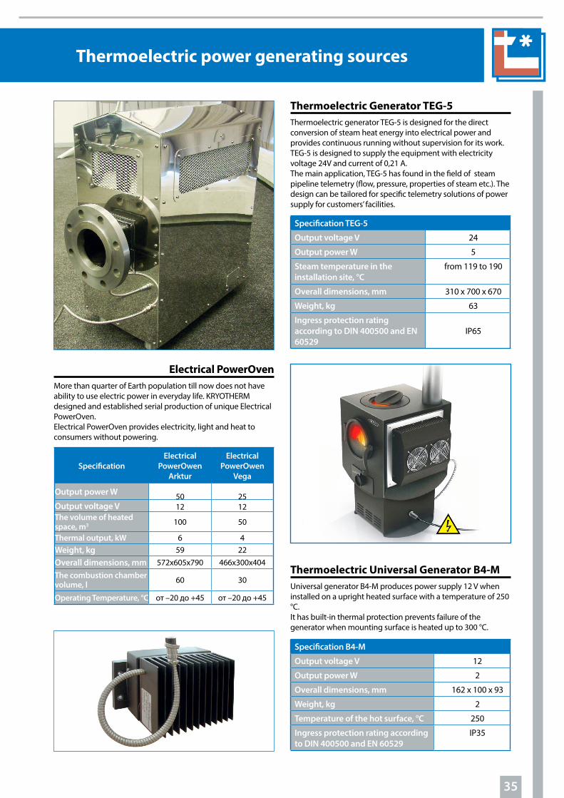
Thermoelectric Generator GTG-200
The company Kryotherm jointly with the company “Ecotechnika” produce thermoelectric generators GTG-200. GTG-200 is a stand alone source of electric power, running on natural gas, propane or propane-butane mixture combustion.Suitable for arranging of stand alone power sources ranging from 200 to 2000 Watts.
GTG-200 is used for cathodic protection of pipelines against corrosion, continuous power supply of consumption meters, radio-link communication, automation and telemechanic tools.
Specification GTG-200
Output voltage V 24
Output power W 200
Overall dimensions, mm Diameter 600,Height 1030
Weight, kg 130
Life time, not less than, years 10
Thermoelectric Generator TEG-30
The thermoelectric generator TEG -30 operating on gas fuel used to provide the electric power for equipment of gas distribution stations by converting thermal energy from the combustion of gas fuels into electricity.
Thermoelectric power generator TEG-30 allow to:
- create a simple and reliable electric power source for supplying, gathering and transmitting data systems, stand alone from the external energy sources;- reduce costs by eliminating the need to connect with the regular electric power lines.
Specification TEG-30
Output voltage V 24
Output power W 30
Overall dimensions, mm 400 x 700 x 930
Weight, kg 76
Fuel consumption, m3/h 0,135
Input gas pressure, kP 3
35
АннотацияThermoelectric power generating sources
Specification TEG-5
Output voltage V 24
Output power W 5
Steam temperature in the installation site, °C
from 119 to 190
Overall dimensions, mm 310 x 700 x 670
Weight, kg 63
Ingress protection rating according to DIN 400500 and EN 60529
IP65
Specification B4-M
Output voltage V 12
Output power W 2
Overall dimensions, mm 162 x 100 x 93
Weight, kg 2
Temperature of the hot surface, °С 250
Ingress protection rating according to DIN 400500 and EN 60529
IP35
Thermoelectric Generator TEG-5Thermoelectric generator TEG-5 is designed for the direct conversion of steam heat energy into electrical power and provides continuous running without supervision for its work. TEG-5 is designed to supply the equipment with electricity voltage 24V and current of 0,21 A.The main application, TEG-5 has found in the field of steam pipeline telemetry (flow, pressure, properties of steam etc.). The design can be tailored for specific telemetry solutions of power supply for customers’ facilities.
Thermoelectric Universal Generator B4-MUniversal generator B4-M produces power supply 12 V when installed on a upright heated surface with a temperature of 250 °C.It has built-in thermal protection prevents failure of the generator when mounting surface is heated up to 300 °C.
Electrical PowerOvenMore than quarter of Earth population till now does not have ability to use electric power in everyday life. KRYOTHERM designed and established serial production of unique Electrical PowerOven. Electrical PowerOven provides electricity, light and heat to consumers without powering.
SpecificationElectrical
PowerOwen Arktur
Electrical PowerOwen
Vega
Output power W 50 25Output voltage V 12 12The volume of heated space, m3 100 50
Thermal output, kW 6 4Weight, kg 59 22Overall dimensions, mm 572х605х790 466х300х404The combustion chamber volume, l 60 30
Operating Temperature, °C от –20 до +45 от –20 до +45

36
Company profile
KRYOTHERM was founded in 1992 out of a large Soviet Union’ research institute engaged in development of thermoelectric devices and subsystems for military and aerospace industries. High production capacity, flexibility of technological equipment, use of modern technologies, and professional management make KRYOTHERM a reliable supplier of thermoelectric coolers and subsystems for more than 500 companies all over the world. Now thermoelectric products are
widely applicable in various human activities, e.g. in industrial and consumer coolers, medical and electronic instruments, telecommunication and radio electronic equipment. The activities of KRYOTHERM are directed to providing safe, reliable, highly effective products, best service and full engineering and technical support for our customers. Since the very beginning, KRYOTHERM has satisfied a unique niche in the thermoelectric high technology market due to adhering to the company’s missions that are as follows:— To design and manufacture highly efficient and reliable thermoelectric products;— To carry out scientific researches to develop and implement modern technologies as well as to provide continuous improvement of existing products quality and reliability;— To find the best thermoelectric solutions for the customers;— To offer the best customer-orientated services to meet all the customer’s expectations.
The overall technological cycle of thermoelectric devices production is performed on the company’s premises.
The cycle starts from synthesis of thermoelectric semiconductor materials, cutting into pellets, and deposition of antidiffusion coatins continues with modules assembly and treatment, and finished with packaging and shipping to customers. The quality system used by KRYOTHERM includes continuous control over all technological stages and testing of finished products.
KRYOTHERM continuously expands and improves the range of products. At present there are more than 250 types of thermoelectric devices in the company Product Line. Taking into account additional options, the total list includes several thousands of items in serial production that are able to perfectly satisfy the needs of most of the customers. Upon customer’s request KRYOTHERM can develop and produce a pilot batch of a new type of thermoelectric module within a few weeks. The staff of the company is more than 200 employers, including 12 PhDs.
Design and manufacturing of customized thermoelectric devices and subsystems is one of KRYOTHERM’s core businesses. More than forty years experience in the field of thermoelectricity enables us to offer the most efficient thermoelectric solutions to fully meet customer needs and requirements.KRYOTHERM systematically improves the quality and parameters of products, expands their range and offers favorable conditions for cooperation. Technical parameters and high reliability of the thermoelectric devices produced by KRYOTHERM fully correspond to world-class standards.
High production capacity enables KRYOTHERM to be cost competitive. KRYOTHERM has a well-earned reputation for product reliability and longevity. The company’s financial stability, experience and high quality of thermoelectric products rank KRYOTHERM as a highly reliable and trustworthy partner.

37
Company profile
Supply of high quality products that fully satisfy the customer requirements is the most important target of KRYOTHERM .
A thermoelectric cooler (TEC) is a solid-state device consisting of thermoelectric pellets of p-type and n-type (TEE) mounted by soldering between two ceramic plates by means of bounding copper tabs. TEEs are produced of crystalline alloys of Te and Bi with semiconductors dopes. The alloys have good soldering ability and owing to this construction ensures high reliability level of TEC on the whole. It is well known that the failure rate of one soldered joint does not exceed 10-9 degree. This means that depending on the number of TEEs in the TEC the theoretical level of the failure rate would be within the range from 0,05 to 0,5 ppm. This theoretical range was confirmed many times by tests made in-house and applications on site on customers’ premises providing that the mounting and operation instructions were observed.
Application of statistic analysis methods to “from start to finish” production processes in real-time assures continuous control over the quality of the products. Control over quality and stability of each production step starts from inspection of received raw-materials and continues up to inspection of the ready to ship products. Periodical and qualification tests are done by an approved schedule. This results in KRYOTHERM to supply thermoelectric products with failure rates of less than 1 ppm. Accuracy and stability of the most important production steps are controlled by a method of estimation of deviations distribution from nominal values of controlled parameters inside one production lot and their alterations from one lot to another.
Quality & Reliability
Improper semi-finished and finished products are sorted out from production flow and placed in a rejected parts store. In case the quantity of improper parts exceeds an allowed value the whole production lot is placed into the rejected parts store and production process is stopped until the reasons for the failure is defined and countermeasures are taken. That also prevents the possibility of such failures in future.
The statistical method also enables taking preventive measures thus eliminating possibility of technology process parameters deviation and the probability of their re-appearance. The aforementioned methods have been successfully used by KRYOTHERM for many years and allow us to guarantee of ultimate reliability of TECs for different applications. It should be noted that the TEC error-free running time mostly depends on application conditions. According to results of tests performed by KRYOTHERM and various customers the Mean Time Before Failure for TECs constantly switched-on at a room temperature exceeds 300000 hours providing that the TEC was correctly installed on an appropriate heat-sink. On the other hand reliability of TECs used in conditions of electric current direction changing with fast temperature changing usually is measured as a number of temperature cycles with indication of maximum and minimum temperature values on TECs surfaces and speed of temperature changing. A special technology used while production of such kind of TECs during mechanical stresses arising during fast temperature changes. The TECs reliability is influenced by many factors including operating temperature, method of mounting on a heat sink, moisture protection, power supply, and the correct application of the thermoelectric system in whole.

Аннотация
38
Company profile
For customer satisfaction through effective application of thermoelectric products KRYOTHERM has developed and has been implementing a quality management system (QMS), which demonstrates our ability to consistently supply products that meet customer and statutory requirements, including continual improvement of processes and prevention of nonconformity of products. Company QMS is approved by TUV Rheinland certification centre as completely meeting the requirements of ISO 9001:2000 Standard. It is extended to all activities starting from suppliers selection, careful input control of materials and components, control of the manufacturing process, and tests of finished products. Constant improvement and development of process control methods provide the necessary conditions for high quality device production to meet the ever-increasing demands of KRYOTHERM’s customers.
3. Transportation tests (GOST 15150);4. Effect of high humidity (for sealed coolers) (Т=+27°C, relative humidity 100 %);5. Cyclic variation of ambient temperature (MIL-STD-883, method 1010);6. Life-time tests (1000 h, I = 0,75Imax, Th = 27°C); 7. Temperature cycling (test +40°С / +90°С with change of current polarity);8. Control of insulation resistance.
Reliability tests are performed for TE coolers for which more strict requirements to operational reliability are specified.Reliability tests include the following:1. Strict temperature cycling (test 0 °С/+100 °С with current polarity reversal);2. Temperature cycling (test +40 °С/+90 °С with current polarity reversal);3. High temperature storage (+85 °С);4. Low temperature storage (–40 °С);5. Cyclic variation of ambient temperature (MIL-STD-883, method 1010);6. Storage at high humidity — for sealed coolers (+85 °C, relative humidity 100 %).
Standardized tests are aimed at confirmation of the efficiency and advisability of introducing changes in the production methods and in new materials and components using. The content of tests is determined by the type of supposed changes. All inspections and tests results, unless otherwise specified, are conducted under normal climatic conditions, i.e. ambient
Methods of quality and reliability control
A distinctive feature of KRYOTHERM is an individual approach to each customers requirements. KRYOTHERM offers a wide range of products for different applications and confirms the high quality of products by multiple tests carried out in accordance with the company QMS. Large varieties of measuring and test equipments are used for quality inspection.
The tests are classified as following:1. Acceptance tests; 2. Periodical tests;3. Reliability tests;4. Standardized tests.
Acceptance tests are aimed at control of the conformity of devices to KRYOTHERM standards and customer’s specification. 100% of the produced goods are subject of these tests. Acceptance tests include the following.1. Control of geometrical dimensions;2. Control of electrophysical parameters (e.g. for TEC it would be AC resistance and thermoelectric merit-factor); 3. Visual inspection;4. Check for compliance with the customer’s specification.
Periodical tests are aimed at control of the technological processes used for products manufacturing. Periodical tests are performed on all types of devices at least once a year. In case existing technological processes are modified or new processes are introduced additional periodical tests of the products manufactured by using the new or modified technology are carried out. Periodical tests conform to the requirements of MIL-STD-883 and GOST 20.57.406, 20.57.406-81, 15150. Periodical tests include the following: 1. Strength tests under sinusoidal vibration (MIL-STD-883, method 2002);2. Strength tests under single mechanical shocks (MIL-STD-883, method 2007);
temperature 25±10°С, relative humidity of air 45–80 %, atmospheric pressure 84–106,7 kPa (630–800 mmHg).Quality control of production and shipment of every lot are accompanied with flow-process identification documents containing the lot number and information about its technological steps and conditions, including information about used materials and components. These sets of document provide products history traceability after they are delivered to the customer. According to the QMS standards all the documents are kept for 3 years.Additional tests can be performed by special customer’s requests. The content and parameters of these tests are agreed upon with the customer and depend on the anticipated TEC application. Tests results detailed information with description of the inspection methods is available on the company official web site http://www.kryotherm.ru.

Аннотация
39
TEC installation instructions
There are two main methods of the mounting: by means of mechanical pressing and by means of soldering (in this case the TEC should have a metallized working surface (or surfaces).
1. Lapped TEC features Copper and aluminum alloys are widely used as heat sink ma-terials because of the low heat resistance. These materials have high thermal conduction. The TECs are lapped during manufac-turing to guarantee of good thermal contact between the TECs’ surface and the heat-sink. TECs could be supplied with working surfaces flatness and parallelism down to 5 micrometers. Correct mounting provides minimal TEC overheating and increase the reliability and efficiency of the thermoelectric system. It should be noted that in case of necessity to use two or more TECs under one heat-sink KRYOTHERM supplies TECs lapped to one height (within one production lot). It must not be forgotten that if TECs of high accuracy lapped surfaces are used, the adequate accu-racy of working surfaces of heat-sinks and other construction elements that contact with working surfaces of TEC should also be provided. Lapped TEC Mounting Instruction:Please follow this instruction of mounting of KRYOTHERM’ lapped TECs to a thermoelectric cooling assembly, which con-sists of a hot side heat sink, TEC and a cold plate (the same mounting steps are applicable for other cases as well). Locate mounting holes as close to the opposite edges of TEC as possible to avoid bends and deformation of the heat-sink and cold plate during assembly. Moreover, it is advisable that the bolt holes are arranged on the line of stiffening ribs of the heat-sink.1. Prepare the surfaces of the heat-sink and plate. Please note that the heat-sink and the cold plate areas that are to contact the TEC should have the flatness of at least 0,025 mm (25 mi-crons or better). 2. Control the lack of burrs on the surfaces of the heat-sink and plate, 100 %. Any metal burrs must be removed from the heat sink.3. Thoroughly clean and degrease the thermoelectric cooler, the heat-sink and the cold-plate.4. Apply a thin and uniform layer of heat conducting paste on one of the joined surfaces. 5. Mount the thermoelectric cooler by its hot side to the heat-sink. Thoroughly and with uniform effort grind in the thermoe-lectric cooler to the heat-sink surface till an obvious resistance to the TEC movements appears. It should be taken in to con-sideration, that to provide effective heat transfer the contact between the ceramics surface of the TEC and the metal surface of the heat sink should be as direct as possible. The heat con-ductive paste is used mainly to improve thermal conductivity across the interface.
TEC type Pm (kg/cm2)Micro TEC 2- 6Standard single-stage TEC 5- 12High efficient single-stage TEC 8-12Multistage TEC 3- 10
Please use the following formula to determine the required screw torque.T= Pm *Sm* Nm* K *d/NWhere: T - screw torque; Pm - mounting pressure; Sm - total surface area of TEСs in assembly;Nm – number of thermoelectric coolers in the assembly;N - number of screws;K - given coefficient of friction (for example, K=0,2 for steel; K=0,15 for nylon);d - screw nominal diameter.
2. Metallized TEC mountingKRYOTHERM supplies TECs with metallization of one or both ceramics surfaces. Metallized TECs are not purposed for lapping. Metal coating allows to mounting of this kind of TECs on the heat-sink and cold plate by solder. TEC’s metallized surfaces could be pre-tinned with 95oC melting temperature solder to ease TEC’s mounting.
By special request solder of 117°C melting temperature could be used for pre-tinning of standard TECs, and for TEC’s with HT(150) the solder of 139°C melting temperature. TECs with processing temperature up to 200°C can be also pre-tinned with solder of 183°C melting temperature.
KRYOTHERM’ gold-coated metallized TEC’s are specially produced for applications where non-flux solders should be applied.
6. Remove excessive paste appearing on the TE cooler edges. 7. Perform operation of p.p. 4-6 for the thermoelectric coolers cold side and the plate being cooled. In this case it is required to move the plate slightly along the thermoelectric coolers cold side. 8. Tighten the hot heat-sink and the plate to be cooled to each other using heat insulating bushes. Use the heat insulating bushes made of polycaproamide (caprolon) is recommended. Tighten the assembly with extreme care turning the tighten-ing screws one after another in several steps and control the connection between the TEC and the plate. If several thermoe-lectric coolers are installed in one assembly then the heat-sink and plate should be tightened beginning from the screw near-est to the centre of assembly. Note: KRYOTHERM recommends the following values of mounting force (Pm) during assembly of non-metallized TECs:

40
TEC installation instructions
During TECs mounting by soldering special attention should be paid to proper coating of the surfaces of the TEC and the heat-sink with solder. It should be aimed at reduction of the soldering layer during soldering because its’ thermal conductivity is worse than the thermal conductivity of the direct contact of the ceramics and the heat-sink.
Metallized TEC Mounting InstructionPlease follow this mounting instruction to attach KRYOTHERM’ metallized TECs to a thermoelectric cooling assembly, which consists of a heat-sink and TEC. The heat-sink surface should be adapted for soldering. The heat-sink should be made of proper material or have proper coating, for example, of copper or nickel.1. Prepare the surfaces of the heat-sink and plate. The surfaces of the heat-sink should have flatness of at least 0,05 mm (50 mi-crons) on the area of the TEC installation. 2. Control over the lack of burrs on the surfaces of heat-sink. In case of burrs’ availability they should be removed.3. Thoroughly clean and degrease the thermoelectric cooler and the heat-sink.4. The heat-sink surface should be covered with flux. 5. Heat the heat-sink surface up to the temperature exceeding the temperature of assembly solder (given in the TEC specifica-tion) by 5-10°C.6. Put the TEC onto the heat-sink surface and wait for several seconds till the solder on the TE cooler melts and the exces-sive flux evaporates. When all solder is melted the TE cooler will tend to float on the solder. Slight blow-off and holding down of
the TE cooler will improve its installation. In cases where more than one TE cooler is used in the same assembly unit, these coolers should be held down with an object having the surface of the required size and the required tolerance of flatness dur-ing the soldering.
7. Wait till the assembly cools down to the room temperature.8. Wash the assembly in hot flowing water and clean using a brush and cleaning agent, (for 1-2 minutes).9. Dry the assembly in a drying chamber at T=75˚C for 30-40 minutes.
3. Operating temperatureTwo factors define reliability of TEC at different operating temperatures. The first is acceleration of copper entry from the connecting tabs to semiconductor material and its’ deg-radation at temperature more than 90˚C. For prevention of this process nickel barriers that exclude possibility of cop-per diffusion are used. The second is correct definition of TEC operating temperature regarding melting temperature of TEC assembly solder. Actually assembly solders with fol-lowing melting temperatures are used: 139˚C, 183˚C and 232˚C. Operating temperatures are up to 120˚C, up to 150˚C and up to 200˚C, accordingly.
The third factor that doesn’t influence on TECs’ reliability but defines the thermoelectric systems’ efficiency is decreasing of cooling capacity and maximal temperature difference at decreased operating temperatures. E.g. if the maximal tem-perature difference at Th = 27˚С is 75˚C, then at Th = 50˚C it would be 85˚C and at Th = 70 ˚C it would be 93˚C. In case of the necessity to work at low temperatures KRYOTHERM can supply special TECs.
4. Soldering of lead wiresKRYOTHERM supplies TEC’s with attached lead wires to fa-cilitate TEC’s installation and power supply connection. Wire cross section and length could be specified by the customer. The minimum wire length is 20 mm.
5. TEC Moisture Protection Sealant OptionsTo protect TEC’s from moisture and condensation KRYO-THERM suggests sealing options when TECs are sealed along the perimeter by silicone, epoxy or urethane sealant that are denoted by letters S, E, U in the name of thermo-electric cooler.
Two of the most common TECs perimeter sealants are used as following.Silicone (S) is an all pur-pose sealant that exhibits good sealing character-istics and retains its elas-tomeric properties over a wide temperature range, from -60 up to 200°C. The sealant is non-corro-sive to many chemicals and exhibits good electri-cal properties with low thermal conductivity. Epoxy (E) is a highly ef-fective barrier to moisture with working temperature range from -40 up to 130°C. The material exhibits a low dielectric constant and low coefficient of thermal expansion. Epoxy sealant is ideal for long life appli-cations.

41
TEC installation instructions
6. Thermoelectric ArraysSeveral TECs wired together is commonly known to as a TE ar-ray. The decision to wire TECs in series or in parallel is primar-ily based on available input power requirements. TE arrays are commonly used for providing higher heat pumping capacity and could be more efficient than a single TEC by advantage of dissipating of heat over a larger surface of the heat-sink.
7. TEC Power Supply FeaturesTo determine the negative and positive TECs leads turn the TEC so that the ceramic plate with electrodes or lead wires is on the bottom and the tabs (or the lead wires) direct to you. In this case the tab / lead wire at the right is positive and the tab / lead wire at the left is negative. As soon as the TEC is connected to respective DC power supply source its bottom side will be-come hot and its upper side cold.It is also easy to determine TEC polarity by the color of the lead wires. The red lead wire is attached to the positive and the black one to the negative lead. To get higher efficiency of a thermoelectric system the power supply ripple should not exceed 5% (the maximum allowed level is 10%) for single and 2% for multistage TE coolers. Using a regulated DC power supply it is possible to maintain the tem-perature on the object being cooled with the accuracy down to 1°C. By use of temperature sensors and temperature control-lers the high precision temperature stabilization of the object could be provided with the accuracy down to 10-5 °C.TEC operating mode (the required maximum cooling capac-ity and efficiency) predetermines the voltage rating to be supplied to one TEC. It is highly important to remember that supplied voltage to each TEC should not exceed the maximum voltage (Umax) specified for this particular type of TEC.For example, in case of high performance TECs such as FROST, SNOWBALL, and ICE series with the Umax of approximately
16 Volts, KRYOTHERM recommends to supply the TEC at 12 Volts, which is around 75% of their specified Umax. and considers this way of choosing TEC voltage to be optimal to provide large cooling capacity (Qc) at high-rated efficiency of a TE cooler. Coefficient of performance (COP) is a measure of ef-ficiency of TEC and is defined as TEC’ Qc divided by the electric input power (P). When KRYOTHERM high performance TECs are fed with voltage of above 12 Volts, the increase in TEC cooling capacity is negligible and COP of TEC drops.
To provide high COP for a thermoelectric system that oper-ates at a relatively low ΔT (ΔT << ΔTmax) it is recommended to mount several TECs into the system and supply each of the TECs with a lower voltage of around 0,25…0,5 of Umax value. If is necessary to increase the specified cooling capacity of FROST, SNOWBALL, or ICE TECs, they should be supplied with voltage of above 12 Volts while the special care should be tak-en to provide effective dissipation of the heat created from the TEC hot side.
The same principle of voltage optimization of supplying TEC’s with 75% of their Umax is applied to all TE coolers, although their Umax may be different from the one mentioned above. At the same time, heat dissipation from the hot side and power supply characteristics should necessarily be taken into consid-eration in each particular case.
For high performance powerful TECs of DRIFT series, the opti-mal supplied voltage ranges of 12 - 18 Volts to achieve greater cooling capacity at the highest possible COP value.
When calculating electrical parameters of TEC working point, it should be noted that once the TEC is in its running mode, the input current goes down by 20 - 35 %. According to the See-beck effect, the increase in temperature differential between the TEC’s hot and cold sides results in thermal electromotive force (EMF) generation. In fact this EMF is a counter-electro-motive force working toward power supply and reducing the current running across the TEC.


![Thermoelectric Seebeck and Peltier effects of single ...carbonlett.org/Upload/files/CARBONLETT/[008-015]-04.pdf · 8 Thermoelectric Seebeck and Peltier effects of single walled carbon](https://img.dokumen.tips/doc/110x75/5b546c047f8b9a1f648cff2d/thermoelectric-seebeck-and-peltier-effects-of-single-008-015-04pdf-8-thermoelectric.jpg)