Embed Size (px)
Citation preview

Thermodynamic Considerations in the. Production of Bulk Ferro Alloys (Fe-Mn, Fe-Cr and Fe-Si)
R.P. Goel National Metallurgical Laboratory
Jamshedpur 831 007.
1. Introduction
The above mentioned ferro alloys are produced commercially by reduction smelting of their oxide minerals with, coke or charcoal in a submerged arc furnace and, to a lesser extent, by a metallic reductant such as aluminium. In general, the overall reduction reactions are highly endothermic, thus, requiring large thermal energy inputs.
In this paper, the thermodynamic principles. underlining reduction smelting of oxides are discussed with the help of free energy-temperature (Ellingham) ,diagram with a focus on the role of direct reduction, the smelting temperatures required for a given oxide mineral, the thermal energy requirements, the suitability of carbon as reductant, the alloy grade and inpurity levels, the slag-metal equilibria and the formation of carbides.
2. Ellingham Diagram
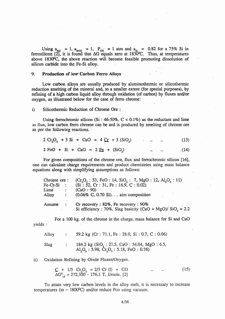
Figure 1 is an Ellingham diagram which shows the standard Gibbs energy of formation of various oxides as a function of temperature, with respect to one mole of oxygen gas [1].
a) When so formed, the more stable oxides appear on the lower part of the diagram in the order FeO, P4010, Cr203, MnO, Si02, A1203, MgO and CaO. Thus, if conditions are made favourable for the reduction of MnO, then the oxides of iron, phosphorus and chromium will also be reduced.
b) For a given oxide mineral, the oxides below it on the Ellingham diagram are stabler and therefore, the elements of the latter (such as Al, Si and Ca) could readily act as reducing agents. This principle is utilized in metallothermic reduction processes.
c) Whereas most lines in the Ellingham diagram slope upward, the CO line slopes downward because of entropy considerations. Thus, there is a tempera-ture above which CO is more stable than the oxide mineral to be reduced. However, the actual operation may have to be conducted at temperatures higher than the temperature of intersection between MO and CO lines in order to enhance the reaction rates and facilitate metal-slag separation.
d) All the lines plotted in the Ellingham diagram correspond to standard states (pure condensed substances). For impure oxides, the line would rotate, clockwise (with respect to zero temperature) indicating greater ease of forma-tion; conversely, for impure elements, the lines would rotate anti-clockwise.
4.01

3. Direct vs Indirect Reduction
MO + C = M + CO 110 .. direct
MO + CO = M + CO2 .. indirect
The indirect reduction is more exothermic. (releases an extra 290 kllg.mcle) relative to the direct reduction: Consequently, the energy efficiency of a process could be significantly enhanced by utilizing the CO formed by direct reduction for subsequent indirect reduction as accomplished in the iron-making blast furnace. However, the latter calls for a long stack and elaborate burden preparation so that descending charge could be preheated and reduced indirectly by the upward moving hot gases before getting directly reduced. However, the relatively small scale of ferro-alloy operations does not permit high shaft furnaces and consequently, most of the CO generated by direct reduction leaves the furnace without being utilized in any indirect reduction reaction.
4. Smelting Temperature
The final products are molten alloy and slag. The alloy composition should be within the specified/desired limits and their temperatures should be high enough ('-.100°C above the liquidus) to impart adequate fluidity for good separation. In the case of ferro-manganese, the equilibrium pressure of CO produced from the reaction.
MnO(s) + C(g) = Mn(1) + CO .. .. (1)
AG°, = 290,350 - 173.25 T J/g.mole [2]
reaches 1 atm at about 1400°C (corresponding to the intersection of ,MnO and CO lines on the Effingham diagram).. This temperature allows good slag-metal separation and hence is the normal smelting temperature.
It should be noted, however, that even if an equilibrium pressure of 1 atm for CO could be achieved at somewhat low temperatures, the need for a clean metal-slag separation (if a slag is formed) may necessitate high smelting temperatures.
5. Thermal Energy Requirements
As stated earlier, production of ferro-alloys is generally an energy intensive operation mainly due to the endothermic reduction reactions as shown below:
Enthalpy' Change 6, H°2 g Ref.12-3] lcJ/g.Mol kWh/kg-metal
Mn02(s) + 2 C = Mn(s) + 2 CO 300.0 1.52 .. .. (2)
Cr203(s) + 3 C = 2Cr(s) + 3 CO 803.1 2.15 .. .. (3)
Si02(s) + 2 C = Si(s) + 2 CO 689.8 6.82 .. .. (4)
4.02

Additional heat must be supplied for melting the metal and slag and raising their temperatures (for clean separation) as well as the gas temperature to the 'requiAte values. Further, heat losses to surroundings and cooling water must be provided for. As a result, the, heat requirement increases significantly; for manganese it was . estimated to be 2.45 kWh/kg. (see Appendix A). Because of such large thermal requirements, it is a standard practice to procduce ferro-alloys, in submerged arc furnaces, wherein the arc provides the necessary heat thus maintaining the reaction zone at suitably high temperatures.The final state of the metal-slag bath is governed by the hearth temperature, which should be reasonably high to effect metal-slag separation.
6. Alloys Grade and Impurity Levels
The Ellingham diagram suggests that all the oxides of iron and phosphorus would get reduced during reduction smelting of MnO, Cr203 as well as Si02. As a result, the overal grade of the molten alloy is determined by the extent of oxide reduction and the burden of iron oxides and other easy-to-reduce oxides in the charge. The slag composition is determined by the total gangue from ore, fuel, flux, etc., besides the unreacted mineral oxide.
If the alloy specifications call for a maximum limit on phosphorous content, it must be adjusted in the burden itself (such as through mineral beneficiation) as there are no commercially established technologies available to remove phosphorous from the molten ferro alloys [4].
7. Slag Metal Equilibria
The reduction of oxide minerals of iron, manganese and chromium takes place in stages as shown below :
Fe203----Fe304----Fex0
Cr203----Cr0----Cr
The reduction of Mn ores upto the stage of Mn304 occurs by thermal dissocia-tion and indirect reduction (like that of iron ores to Fe304) and thereafter, by direct reduction.
In the last stage of direct reduction of oxides, the slag-metal phases are believed to approach thermodynamic equilibrium as follows :
(MO) + C (alloy) = M + CO(g),
AG° = -RT In K = -RT In [am pcd(amo• ac)]
4.03
Fe

Where parentheses for MO indicate the slag phase and underline for C, M indicates the liquid alloy phase. Thus, a knowledge of the equilibrium constant K, through standard Gibbs energy data, is useful in determining the ways to promote a reaction in the desired direction. Thanks to the extensive thermodynamic studies done on liquid iron solutions and oxide. slags [5-7], the activities of various compo-nents can be estimated and used to assess the extent of equilibrium achieved in' a given process.
The multiphase equilibria such as those pertaining to feno alloy processes have been analyzed by several investigators [8-11] with the help of the phase rule and Gibbs energy minimising techniques for predicting the distribution of a metal between the slag and alloy phases for different charge compositions and operating conditions of temperature and pressure. '
In a recent study, Ding and Olsen [12] have analyzed the silico manganese process by considering the main reactions as' follows :
(Si02) + 2 C = Li + 2 .CO(g) (5)
(Mn0) + C = Mn + CO(g) .. (6)
(Si02) + 2 Mp, = + 2 (Mn0) (1)
The carbothermic reduction of silica in slag (reaction 5) being very sluggish, they used only reactions (6) and (7) for describing the equilibria as shown in Figure 2 which indicates that, for a given alloy compostion (%Si), the slag composition will shift to a lower (Mn0) content in slag with increase in temperature. Another advantage of increasing the temperature will be to improve the slag/metal ratio significantly.
The slag produced in ferro-alloy process usually contains appreciable amounts of the valuable metal as shown below [13].
Alloy Mn Cr C Si
High C Ferro Chrome 65.5 7.0 4.5 Med C Ferro Manganese 72 2.0 0.8
Slag Composition Slag/ Mn0 Cr203 Ca0 Mg0 Si02 A1203 Metal
Ratio
High C FeCr 6.2 37.2 30.6 26.0 0.83 Med C FeMn 14 38 5.0 28.0 3.0
4.04

If the metal loss is considered excessive, such as in the case of medium carbon Ferro-manganese shown above, and if the process economics warrants then, in the opinion of this author, a proper control of slag composition should help lower the metal loss. In the case of ferromanganese, a slight, increase in slag basicity will tend to increase the activity of MnO in slag as shown in Figure 3, thereby lowering the (Mn0) content. Furthermore, a higher basicity should also help lower the phosphorus content of the alloy.
8. Carbide Formation
From an' economic viewpoint, coke-carbon is considered a preferred reductant. However, the ferro-alloy thus produced contains high , levels of carbon promoting formation (precipitation) of metal-carbides such as :
7M,a(1) + 3 C = Mn7C3(s) (8)
7Cr(1) + 3 C = Cr7C3 (s) •• .. (9)
Si(1) 0) = SiC(s) • •
These carbides are refractory materials and the low temperature at the hearth bottom is likely to help precipitate. Cr7C3 and SiC which may cause furnace bottom build up. It is to be noted that in the case of manganese and chromium, the equilibrium carbide phase after solidification will be mostly M23C6 ; at the smelting temperatures, however, the first carbide to precipitate is likely to be Mn7C3 or Cr7C3 [14].
From a thermodynamic view point, it should be possible to reduce these carbides and recover the metal into the alloy by reacting the former with metal oxide at relatively high ,temperatures, as shown below :
Mm7C3 (s) + 3MnO(s) = l0ln (1) + 3C0(g) (11)
AG°11 = + 937215 - 461.5 T , Jig. mole [2]
For a molten bath saturated with Mn7C3 (amn7c3 = 1) and in contact with solid MnO, with Pco = 1 atm and taking amn = 0.3 for a 75% Mn in ferromanganese alloys [15], one finds that the above reaction becomes feasible ( -ve Gibbs energy) at about 1400°C.
Similary, for
2SiC(s) + Si02(s) = 3Si (1) + 2C0(g)
(12)
AG°12 = 941,192 - 442.1 T , Jig. mole [2]
4.05
Using asic = 1, asio2 = 1, Pa; = 1 atm and as; = 0.82 for a 75% Si in ferrosilicon [2], it is found that AG equals zero at 1830°C. Thus, at temperatures above 1830°C, the above reaction will become feasible promoting dissolution of silicon carbide into the Fe-Si alloy.
9. Production of low Carbon Ferro Alloys
Low carbon alloys are usually produced by aluminothermic or silicothermic reduction smelting of the mineral and, to a smaller extent (for special purposes); by refining of a high carbon liquid alloy through oxidation (of carbon) by fluxes and/or oxygen, as illustrated below for the case of ferro chrome:
i) Silicothermic ReduOtion of Chrome Ore :
Using ferrochromic silicon (Si : 46-50%, C < 0.1%) as the reductant and lime as flux, low carbon ferro chrome can be and is produced by smelting of chrome ore as per the following reactions.
2 Cr203 + 3 Si + CaO = 4 a 3 (Si02) (13)
2 FeO + Si + CaO = 2 Ea + (Si02) (14)
For given compositions of the chrome ore, flux and ferrochromic silicon [16], one can calculate charge requirements and product chemistries using mass balance equations along with simplifying assumptions as follows:
Chrome ore : (Cr203 : 53, FeO : 14, Si02 : 7, MgO : 12,. A1203 : 11) Fe-Cr-Si : (Si : 52, Cr : 31, Fe : 16.9, C : 0.02) Limd • (CaO : 90) Alloy • (0.06% C. 0.70 Si). . . aim composition
Assume Cr recovery 82%, Fe recovery : 90% Si efficiency : 70%, Slag basicity (CaO + MgO)/ Si02 = 2.2
For a 100 kg. of the chrome in the charge, mass balance for Si and CaO yields :
Alloy 59.2 kg (Cr : 71.1, Fe : 28.0, Si : 0.7, C : 0.06)
Slag 184.2 kg (Si02 : 27.5, CaO : 54.04, MgO : 6.5,
A1203 : 5.98, Cr203 : 5.18, FeO : 0.76)
ii) Oxidation Refining by Oixde Fluxes/Oxygen.
C + 1/3 Cr203 = 2/3 Cr (1) + CO (15) AG°15 = 272,350 - 176.1 T, J/mole. [2]
To attain very low carbon levels in the alloy melt, it is necessary to increase temperatures (to — 1800°C) and/or reduce Pco using vacuum.
4.06

10. Summary
This paper showed that a better understanding of the principles of thermody-namics and their application to ferro alloys processes can be very useful in :
0 promoting a smelting reaction in the desired direction, 0 lowering metal losses into the slag phase 0 improving the slag/metal volume 0 lowering the impurity levels in the alloy, and
preventing the formation of unwanted carbides.
There is a greater need to utilize such concepts for optimizing the furnace performance from a thermochemical standpoint.
References
1. Richardson, F.D. and Jeffes, J.H.E., " Thermodynamics of substances of interest in iron and steelmaking", Parts ,I, II and III, JISI, 1948, Vol. 160, p.261-270; Ibid-150, Vol. 166, p.213-235; Ibid-1952, Vol. 171, p.167-175.
2. Elliott, J.F. Gleiser, M and Ramakrishna, " Thermochemistry for steelmaking", Vol. 12, Addison-Wesley Publishing Co., 1963.
3. JANAF Thermochemical tables, 3rd Edition, ACC-NBS, 1985. 4. Chaudhary, P.N. and Goel, R.P., "Dephosphorization of liquid ferro manganese,"
paper presented in this course.. 5. Gaye, H and Welfringer, J., "Modelling of the thermodynamic properties of
complex metallurgical slags", in the Porceedings of the 2nd • Intl Symp. on Metallurgical Slags and Fluxes, Edited by H.A. Fine and D.R. Gaskell, TMS-AIME, Nov. 1984, p.357-375.
6. Goel, R.P., and Kellogg, H.H., "Mathematical description of the thermochemical . properties of iron-silicate slags ,containing lime", Ibid., p.347-355.
7. Iguchi, Y; "Therniochemistry of Ferrous metals", in the Proceedings of the Elliott Symposium on Chemical Process Metallurgy, Edited by P.J. Koros and G.R. St. Pierre, ISS-AIME, June 1990, p.129-147.
8. Ttirkdogan, E.T., and Hancok, R.A., "Equilibrium measurements between carbon-saturated Mn-Fe-Si-Metals and Ca0-A1203-MnO-Si02 Slags", Trans. Inst. Min. Met., Vol. 67, 1957-1958, p.573-600.
9. Rankin, W.J., "Si-Mn equilibrium in ferromanganese alloy production", Trans. Inst. Min. Met., Vol. 88, Sept., 1979, p.C167-174. '
10. Kor, G.J.W., "Equilibria between liquid Mn-Si alloys and MnO-Si02-CaO-Mg0 slags", Met. Trans., Vol. 10B, 1979, p.367-374.
11. Tanaka,' A., "Equilibria between Mn alloy melts saturated with C and various kinds of molten slags and calculation- of the activities", Tetsu-to-hagane, Vol. 66, 1980, p.1474-1483.
12. Ding, W., and Olsen, S.E., "Thermodynamic analysis of the silico-manganese process", Proceedings of the Electric Furnace Conf., ISS-AIME, 1991, p.259-264.
13. Private communication with M.V. Zode, MEL, Dec. 1991. , 14. Binary Alloy Phase Diagrams, Vol. I, Edited by T.B. Massalsld, et. al., American
Society of Wtals, (1986), p.558-575. 15. Healy, G.W., Proceedings of the International Symposium on Ferrous and Non-
ferrous Alloy Processes, CIM, Hamilton, Ontario, August 1990, Edited by R.A. Bergman, 'Pergoman Press, p.97-108.
16. Riss, M., and Khodorovsky, Y., "Production of ferro alloys", Mir Publishers, Moscow, 1967, p.187-1,91.
4.07
0 0. 0 • a
2 -10
(0 * k• ° IA) (C)
-12
-1
•14 10
10
1
1000 SUGGEST•O ACCURACIES (A) I 410
12k.1 42k.1
(9) 1 42kJ
U S
MI I ((NO MINI 11011.11.40 POINI
SUOLIMATION rT 111ANSI /ION r 1.
112 /1120 RATIO 103 ► 10.4► 10"/I
0
II
C •
1407 111//120 RATIO
lilua —CU/COATI 'ilia'n ,' liol:s .„et •■
Ii7
, r , r /----/*•
1/104 1Flu/ 11100 1/10 1404 111113 1110 TEMPERATURE IN DEGREES CEN TIGRADE
200 400 600 000 1000 1200 1400 1600 11100 2000 1
III ((1
2200 .7400 1/10
200 A
-300
-400
.4 Iu-
C c02
/ • 000 • 10
IS
10.4 , 10
-1100 L.•11ANGCS OF STA IE EL EMEN1 OXIDE
1 I 1 1 1 1 I I 1
O 200 400 600 800 1000 1200 1400 1600 1800 2000 TEMPERATURE IN DEGREES CENTIGRADE 14- ABSOLUTE ZERO 10$ 4,1 1013/1
CO/CO2 RA 110 \
-1200
IM le104,
(51
(TI
1011/ 2200 2400
10174
•70 10
N
10-90 111 110 urn (0.60 30 50 10 •42 ,0•34 10'30 1046 1046 \ 0, \
10.20010 ISO 1
• 1110 _ •
N,
C
I— cc 0 105/1
-500
0
0
• -600
0 0
1- CC .700
17
- 800
102
10
Figure 1. The standard Gibbs energies of formation of metal oxides as a function of temperature [1]
4.08

40
MnO Saturation
time end lime 1 silicate saturation
80 60
40 60
V.3
do
MnO
(h) C01111)0Sli:1011S: NV/0.
80 0 20
20
60
51 02
CaO+A1203+MgO
MnO (constant ratio)
Figure 2. Slag-metal equilibria Lreaction 7] at. various silicon contents in the Si-Mn alloy along the solid lines [12]. Complete equilibria are drawn by dotted lines.
Figure 3. Iso-activity lines for MnO in the CaO-MnO-Si02 system at 1500°C [2].
Standard state MnO: Pure solid MnO in equilibrium with melt.
4.09

Appendix - A Thermal Requirements for Smelting Manganese Ore
The overall smelting reaction can be represented as : Mn02(s) + 2 C + Fluxes = Mn (1) + 2 CO + slag (1) ... (A)
Assuming
Metal and slag temperature 1500°C Gas exit temperature 1000°C Slag volume 0.5 kg/metal
and using pertinent thermodynamic data
AH°298 for Mn02 -521,050 'J/g. mole (a)
AH°298 for CQ -110,530 " (b)
Heat content of Mn(1) + 75000 " (c)
Heat content of CO + 31,000 " (d)
Heat content of Slag + 1,780,000 J/kg. (e)
The enthalpy change for reaction (A) is obtained as
AH°A = -H. + 2 Hb + + 2Hd + H.
= [521,050 + 2 (-110,530) + 75,000 + 2 x 31,00] J/(0.055kg Mn)
+ (1,780,000)/2 J/kg Mn.
= 8835 kJ/kg Mn
= 2.45 kWh/kg Mn.
4.10


![Experimental Assessment of Thermodynamic …sco2symposium.com/papers2016/FluidMechanics/065paper.pdfnear the critical point [1]. While the bulk fluid properties generally remain single-phase,](https://img.dokumen.tips/doc/110x75/5f90e8a7175d051ee616ad78/experimental-assessment-of-thermodynamic-near-the-critical-point-1-while-the.jpg)