Embed Size (px)
Citation preview
INSTRUCCIONES PARA LA INSTALACIÓN DE LA VÁLVULASOLENOIDE Y DEL INTERRUPTOR TÉRMICO
THERMAL SWITCH ANDSOLENOID VALVE INSTALLATION INSTRUCTIONS

3
En
glish
INTRODUCTION .................................................. 4 General Information ......................................... 4PRE-INSTALLATION ............................................ 5INSTALLATION .................................................... 5 Vehicle Preparation ........................................... 5 Thermal Switch Installation .............................. 5 Solenoid Valve Installation ............................... 6ELECTRICAL CONNECTIONS ............................. 8 System Wired Normally Closed (N.C.) ............ 8 System Wired Normally Open (N.O.) ........... 10
4
INTRODUCTION
General Information
This manual describes the correct ThermalSwitch and Solenoid Valve Installationprocedures. Following the instructionscarefully will provide the safest and mosttrouble-free operation.
Horton uses the following special noticesto give warning of possible safety relatedproblems which could cause serious injuryand provide information to help preventdamage to equipment.
Danger is used to indicate thepresence of a hazard which willcause severe personal injury, death,or substantial property damage ifthe warning is ignored.
Warning is used to indicate thepresence of a hazard which cancause severe personal injury, death,or substantial property damage ifthe warning is ignored.
Caution is used to indicate thepresence of a hazard which will orcan cause minor personal injury orproperty damage if the warning isignored.
NOTENote is used to notify people ofinstallation, operation, ormaintenance information which isimportant but not hazard related.
5
En
glish
PRE-INSTALLATION
You must follow your company safetypractices, which should adhere to or bebetter than Federal or State approvedshop safety practices and procedures.Be sure that you understand all theprocedures and instructions before youbegin work on this unit.
INSTALLATION
Vehicle Preparation
1. Turn the vehicle ignition off, applythe vehicle's parking brake, andblock the vehicle's wheels.
Thermal Switch
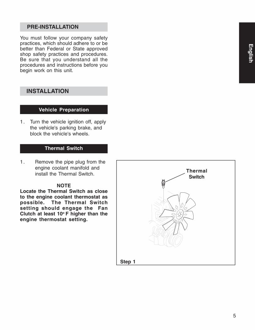
1. Remove the pipe plug from theengine coolant manifold andinstall the Thermal Switch.
NOTELocate the Thermal Switch as closeto the engine coolant thermostat aspossible. The Thermal Switchsetting should engage the FanClutch at least 10o F higher than theengine thermostat setting.
Step 1
ThermalSwitch
6
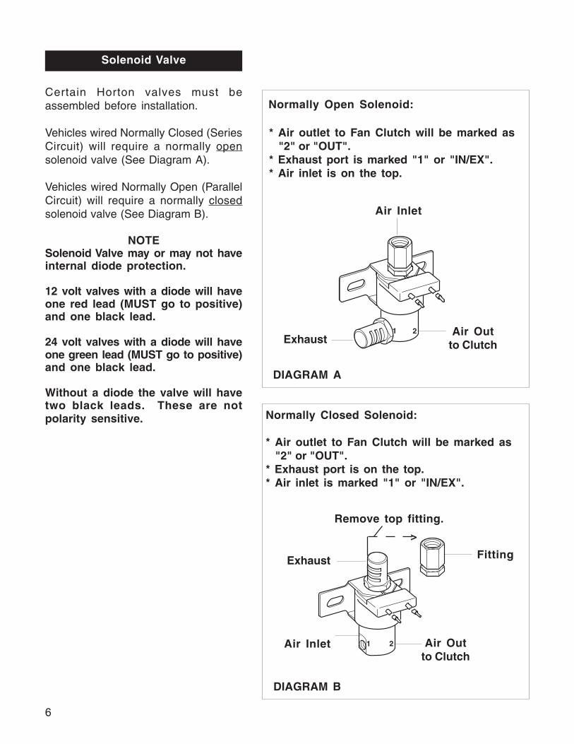
Solenoid Valve
Certain Horton valves must beassembled before installation.
Vehicles wired Normally Closed (SeriesCircuit) will require a normally opensolenoid valve (See Diagram A).
Vehicles wired Normally Open (ParallelCircuit) will require a normally closedsolenoid valve (See Diagram B).
NOTESolenoid Valve may or may not haveinternal diode protection.
12 volt valves with a diode will haveone red lead (MUST go to positive)and one black lead.
24 volt valves with a diode will haveone green lead (MUST go to positive)and one black lead.
Without a diode the valve will havetwo black leads. These are notpolarity sensitive.
2
>
2
1
1
Air Inlet
ExhaustAir Out
to Clutch
DIAGRAM B
DIAGRAM A
FittingExhaust
Air Inlet Air Outto Clutch
Normally Open Solenoid:
* Air outlet to Fan Clutch will be marked as "2" or "OUT".* Exhaust port is marked "1" or "IN/EX".* Air inlet is on the top.
Normally Closed Solenoid:
* Air outlet to Fan Clutch will be marked as "2" or "OUT".* Exhaust port is on the top.* Air inlet is marked "1" or "IN/EX".
Remove top fitting.

7
En
glish
The vehicle's air supply must beclean and free of moisture and oil.
3. Check for proper air pressure tothe Fan Clutch. This measurementshould always be taken at the FanClutch air inlet port.
NOTETo assure maximum horsepowercarrying capacity of the Fan Clutchand to prevent damage to the FanClutch, there must be a minimumpressure of 90 to 120 PSI to the FanClutch upon engagement.
Steps 1-2
1. Mount the Solenoid Valve oneither the vehicle's fire wall orradiator support, in an areawhere the Solenoid Valve will notbe subjected to engine heat,vibration, or road dirt.
2 . Connect the air hose from thevehicle's air supply to theSolenoid Valve inlet port.

8
Steps 1-13
ELECTRICAL CONNECTIONS
Normally Closed (N.C.)
NOTEAn electrical system wired N.C. willrequire a normally open (N.O.)Solenoid Valve.
Also note the N.C. Thermal Switch,N.C. Freon Pressure Switch, andN.O. Solenoid Valve are the onlycontrols absolutely necessary forFan Clutch operation. The N.C.Manual Switch, Air Pressure Switch,and Indicator Light are all optionalcontrols and may be left out of thecircuit.
1. Remove the battery cables from thebattery.
2. Install the Air Pressure Switch intothe air line between the N.O.Solenoid Valve and the Fan Clutch.
3. Mount the Indicator Light andToggle Switch on the dashboard orother convenient location.
NOTEThe Manual Toggle Switch isstamped OFF and ON. OFFposition is for continuous operation,ON position is for automaticoperation. Set the Manual ToggleSwitch to ON position and note thisposition for future reference.
4. Install the N.C. Freon PressureSwitch into the high pressure Freonline of the air conditioning system.
5. Connect the Black lead of the N.O.Solenoid Valve to the vehicleground.
6. Connect the Red (12 Volt) or Green(24 Volt) lead of the N.O. SolenoidValve to one lead of the N.C. FreonPressure Switch.

9
En
glish
7. Connect the other lead of the N.C.Freon Pressure Switch to oneterminal of the N.C. ThermalSwitch.
8. Connect the other terminal of theN.C. Thermal Switch to one terminalof the Manual Toggle Switch.
9. Connect the other terminal of theManual Toggle Switch to the vehicleaccessory or ignition terminal.
10. Connect one terminal of the AirPressure Switch to the vehicleground.
11. Connect the other terminal of theAir Pressure Switch to the IndicatorLight.
12. Connect the other terminal of theIndicator Light to the vehicleaccessory or ignition terminal.
13. Connect the battery cable to thebattery.
Electrical System Operation Check
1. With the engine temperature belowthe Thermal Switch setting, turn onthe ignition and build up airpressure.
2. Disconnect one terminal of the N.C.Thermal Switch. This will engagethe Fan Clutch.
Keep hands and tools clear of thefan blades. The Fan Clutch canengage without warning.
3. Reconnect the terminal of the N.C.Thermal Switch. This will exhaustthe air and disengage the FanClutch.
4. Repeat Steps 1-3 for the N.C. FreonPressure Switch.

10
5. Set the Manual Toggle Switch toOFF. This will engage the FanClutch, the Indicator Light will lightwhen the Fan Clutch is engaged.If the Indicator Light fails to light,check the bulb and the IndicatorLight's ground connection.
NOTEON position is for automaticoperation, OFF position is forcontinuous operation.
Normally Open (N.O.)
NOTEAn electrical system wired N.O. willrequire a normally closed (N.C.)Solenoid Valve.
Also note the N.O. Thermal Switch,N.O. Freon Pressure Switch, andN.C. Solenoid Valve are the onlycontrols absolutely necessary forFan Clutch operation. The N.C.Manual Switch, Air Pressure Switch,and Indicator Light are all optionalcontrols and may be left out of thecircuit.
1. Remove the battery cables from thebattery.
2. Install the Air Pressure Switch intothe air line between the N.C.Solenoid Valve and the Fan Clutch.
3. Mount the Indicator Light andToggle Switch on the dashboard orother convenient location.
NOTEThe Manual Toggle Switch isstamped OFF and ON. ON positionis for continuous operation, OFFposition is for automatic operation.Set the Manual Toggle Switch toOFF position and note this positionfor future reference.
Steps 1-15

11
En
glish
4. Install the N.O. Freon PressureSwitch into the high pressure Freonline of the air conditioning system.
5. Connect the Black lead of the N.C.Solenoid Valve to the vehicleground.
6. Connect the Red (12 Volt) or Green(24 Volt) lead of the N.C. SolenoidValve to one terminal of the N.O.Thermal Switch.
7. Connect the other terminal of theN.O. Thermal Switch to the vehicleaccessory or ignition terminal.
8. Connect one lead of the ManualToggle Switch to the Red (12 Volt)or Green (24 Volt) lead connectingthe N.C. Solenoid Valve to theterminal of the N.O. ThermalSwitch.
9. Connect the other lead of theManual Toggle Switch to the vehicleaccessory or ignition terminal.
10. Connect one lead of the N.O. FreonPressure Switch to the Red (12 Volt)or Green (24 Volt) lead connectingthe N.C. Solenoid Valve to theterminal of the N.O. ThermalSwitch.
11. Connect the other lead of the N.O.Freon Pressure Switch to the vehicleaccessory or ignition terminal.
12. Connect one lead of the AirPressure Switch to the vehicleground.
13. Connect the other lead of the AirPressure Switch to one terminal ofthe Indicator Light.
14. Connect the other terminal of theIndicator Light to the vehicleaccessory or ignition terminal.
15. Connect the battery cables to thebattery.
12
Electrical System Operation Check
1. With the engine temperature belowthe Thermal Switch setting, turn onthe ignition and build up airpressure.
2. Install a jumper wire between theterminals of the N.O. ThermalSwitch, this will engage the FanClutch.
Keep hands and tools clear of thefan blades. The Fan Clutch canengage without warning.
3. Remove the jumper wire to exhaustthe air and disengage the FanClutch.
4. Repeat Steps 1-3 for the N.O.Freon Pressure Switch.
5. Set the Manual Toggle Switch toON. This will engage the FanClutch, the Indicator Light will lightwhen the Fan Clutch is engaged.If the Indicator Light fails to light,check the bulb and the IndicatorLight’s ground connection.
NOTEOFF position is for automaticoperation, ON position is forcontinuous operation.

13
Esp
año
l
INTRODUCCIÓN ................................................ 14Información General ....................................... 14
INFORMACIÓN PREVIA ................................... 15INSTALACIÓN .................................................... 15
Preparación del vehículo................................. 15Instalación del interruptor térmico ................ 15Instalación de la válvula solenoide ................ 16
CONEXIONES ELÉCTRICAS .............................. 18Sistema cableado normalmentecerrado (N.C.) .................................................. 18Sistema cableado normalmenteabierto (N.O.) .................................................. 21
14
INTRODUCCIÓN
Información GeneralInformat
Este manual describe la forma correctade instalar el interruptor térmico y laválvula solenoide. Seguir las instruccionesgarantizará un funcionamiento seguro ysin problemas.
Horton utiliza los siguientes símbolosespeciales para advertir sobre ciertosproblemas de seguridad que podríancausar heridas de gravedad y paraproporcionar información para prevenirdaños al equipo.
Se utiliza para indicar la presenciade un peligro que podría producirheridas graves, mortales o dañosserios a la propiedad.
Se utiliza para indicar la presenciade un peligro que podría producirheridas graves, mortales o dañosserios a la propiedad.
Se utiliza para indicar la presenciade un peligro que puede o podríaproducir heridas leves o daño a lapropiedad.
NOTASe utiliza para indicar informaciónimportante relativa a la instalación,el funcionamiento o elmantenimiento, pero que no implicariesgos personales ni a lapropiedad.
15
Esp
año
l
INFORMACIÓN PREVIA
Se deben seguir las normas de seguridadde la compañía, las cuales deben ajustarseo ser mejores que las Normas deSeguridad Federales y Estatalesestablecidas para talleres de reparación.Asegúrese de entender todas lasinstrucciones y procedimientos deinstalación antes de comenzar a trabajarcon esta unidad.
INSTALACIÓN
Preparación del vehículo
1. Apague el motor, aplique el frenode estacionamiento y bloquee lasruedas del vehículo.
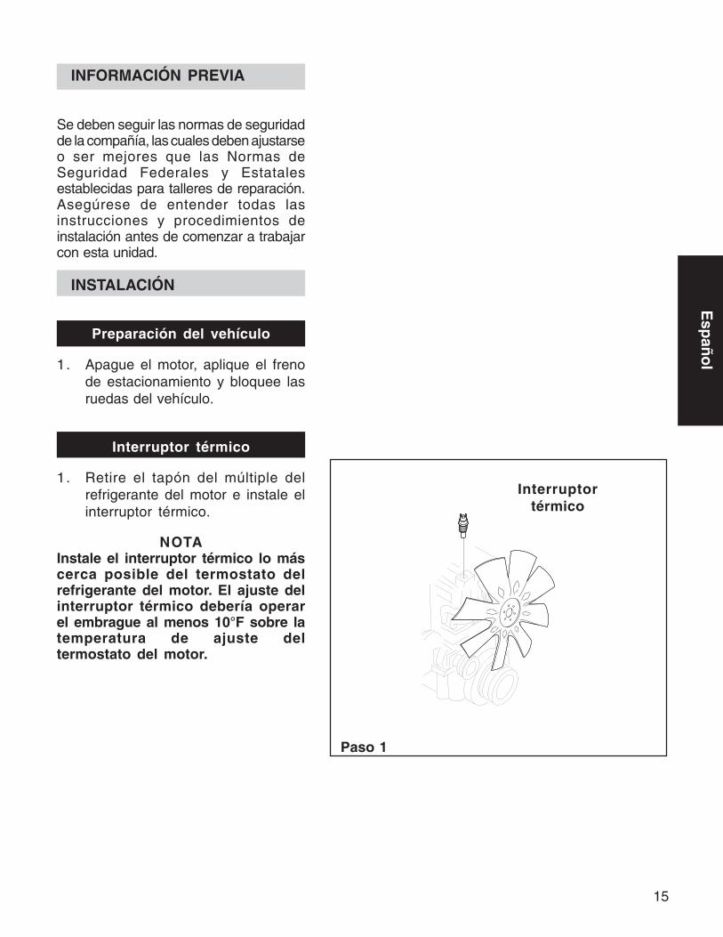
Interruptor térmico
1. Retire el tapón del múltiple delrefrigerante del motor e instale elinterruptor térmico.
NOTAInstale el interruptor térmico lo máscerca posible del termostato delrefrigerante del motor. El ajuste delinterruptor térmico debería operarel embrague al menos 10°F sobre latemperatura de ajuste deltermostato del motor.
Paso 1
Interruptortérmico

16
Válvula Solenoide
Algunas válvulas Horton requieren serensambladas antes de la instalación.
Los vehículos con un sistema eléctricocableado normalmente cerrado (circuitoen serie) requieren de una válvulasolenoide normalmente abierta. (Véaseel Diagrama A.)
Los vehículos con un sistema eléctricocableado normalmente abierto (circuitoen paralelo) requieren de una válvulasolenoide normalmente cerrada (Véaseel Diagrama B).
NOTAUna válvula solenoide puede tenero no tener un diodo de proteccióninterna.
Las válvulas de 12 voltios con diodotendrán un cable rojo (que DEBEconectarse a la terminal positivo) yun cable negro.
Las de 24 voltios con diodo tendránun cable verde (que DEBE conectarsea la terminal positivo) y un cablenegro.
Las válvulas sin diodo tendrán sólodos cables negros. Con éstas noimporta la polaridad.
Entradade aire
Descarga Salida de
aire alembrague
DIAGRAMA B
DIAGRAMA A
Conexión
Solenoide normalmente abierta:
* La salida de aire al embrague estará marcada como “2” o “OUT”.* La descarga estará marcada
como “1” o “IN/EX”.* La entrada de aire se encuentra en la
parte superior.
Solenoide normalmente cerrada:
* La salida de aire al embrague estará marcada como “2” o “OUT”.* La descarga se encuentra en la
parte superior.* La entrada de aire está marcada como “1”
o “IN/EX”.
Quitar la conexión superior.
Descarga
Entradade aire Salida de aire al
embrague

17
Esp
año
l
El suministro de aire del vehículodebe estar limpio y libre dehumedad y aceite.
3. Verifique que la presión de aire quellega al embrague sea la correcta.Esta presión debe medirse siempreen de entrada de aire delembrague.
NOTAPara garantizar una máximacapacidad de conducción de potenciadel embrague y para prevenir dañosal mismo, debe existir una presiónmínima de 90 a 120 PSI al momentode embragar.
Pasos 1-2
1. Monte la válvula solenoide ya seaen la placa cortafuego o en elsoporte del radiador, en un áreadonde la válvula no esté expuestaal calor del motor, a las vibracioneso al polvo del camino.
2. Conecte la manguera de aire desdeel suministro de aire del vehículo ala entrada de la válvula.
FUENTE DEAIRE SECO
VÁLVULASOLENOIDE N.O.
AIRE LIMPIOAL EMBRAGUE
FUENTE DEAIRE SECO
AIRE LIMPIOAL EMBRAGUE
VÁLVULASOLENOIDEN.C.
18
CONEXIONES ELÉCTRICAS
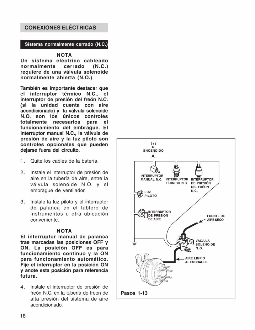
Sistema normalmente cerrado (N.C.)
NOTAUn sistema eléctrico cableadonormalmente cerrado (N.C.)requiere de una válvula solenoidenormalmente abierta (N.O.)
También es importante destacar queel interruptor térmico N.C., elinterruptor de presión del freón N.C.(si la unidad cuenta con aireacondicionado) y la válvula solenoideN.O. son los únicos controlestotalmente necesarios para elfuncionamiento del embrague. Elinterruptor manual N.C., la válvula depresión de aire y la luz piloto soncontroles opcionales que puedendejarse fuera del circuito.
1. Quite los cables de la batería.
2. Instale el interruptor de presión deaire en la tubería de aire, entre laválvula solenoide N.O. y elembrague de ventilador.
3. Instale la luz piloto y el interruptorde palanca en el tablero deinstrumentos u otra ubicaciónconveniente.
NOTAEl interruptor manual de palancatrae marcadas las posiciones OFF yON. La posición OFF es parafuncionamiento continuo y la ONpara funcionamiento automático.Fije el interruptor en la posición ONy anote esta posición para referenciafutura.
4. Instale el interruptor de presión defreón N.C. en la tubería de freón dealta presión del sistema de aireacondicionado.
( + )Al
encendido
Interruptortérmico N.C.
Pasos 1-13
( + )AL
ENCENDIDO
INTERRUPTORMANUAL N.C.
LUZPILOTO
INTERRUPTORDE PRESIÓNDE AIRE
FUENTE DEAIRE SECO
VÁLVULASOLENOIDEN.O.
AIRE LIMPIOAL EMBRAGUE
INTERRUPTORTÉRMICO N.C.
INTERRUPTORDE PRESIÓNDEL FRÉONN.C.
19
Esp
año
l
7
5. Conecte el cable negro de la válvulasolenoide N.O. a la conexión atierra del vehículo.
6. Conecte el cable rojo (12 voltios) oel verde (24 voltios) de la válvulasolenoide a un cable del interruptorde presión de freón N.C.
7. Conecte el otro cable delinterruptor de freón N.C. a de unalas terminales del interruptortérmico N.C.
8. Conecte la otra terminal delinterruptor térmico N.C. a de unalas terminales del interruptormanual de palanca.
9. Conecte la otra terminal delinterruptor de palanca a la terminalde accesorios o de encendido delvehículo.
10. Conecte una terminal delinterruptor de presión de aire a laconexión a tierra del vehículo.
11. Conecte la otra terminal delinterruptor de presión de aire a laluz piloto.
12. Conecte la otra terminal de la luzpiloto a la terminal de accesorios ode encendido del vehículo.
13. Vuelva a conectar los cables de labatería.
19

20
Verificación del funcionamiento delsistema eléctrico
1. Compruebe que la temperatura delmotor esté por debajo del ajustedel interruptor térmico y ponga enmarcha el motor para que seacumule presión de aire.
2. Desconecte una terminal delinterruptor térmico N.C. Estodebería arrancar el embrague deventilador.
Mantenga las manos y herramientasalejadas de las aspas del ventilador.El embrague puede operar en formainesperada.
3. Vuelva a conectar la terminal delinterruptor térmico N.C. Esto dejaráescapar el aire y desconcatará elembrague.
4. Repita los pasos del 1 al 3 con elinterruptor de presión del fréonN.C.
5. Ponga el interruptor de palanca enOFF. Esto enganchará el embraguey se encenderá la luz piloto. Si éstano se enciende, revise el foco y laconexión a tierra de la luz piloto.
NOTALa posición ON es parafuncionamiento automático y la OFFes para funcionamiento continuo.
Sistema normalmente abierto(N.O.)
21
Esp
año
l
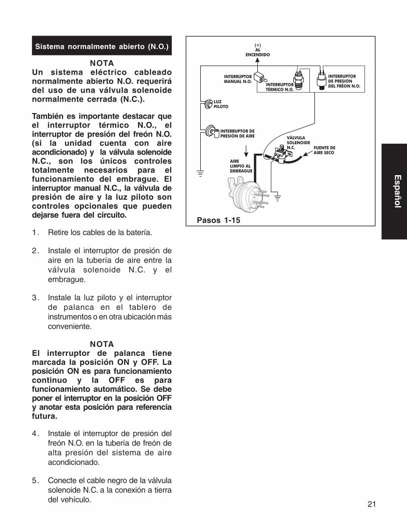
Pasos 1-15
Sistema normalmente abierto (N.O.)
NOTAUn sistema eléctrico cableadonormalmente abierto N.O. requerirádel uso de una válvula solenoidenormalmente cerrada (N.C.).
También es importante destacar queel interruptor térmico N.O., elinterruptor de presión del freón N.O.(si la unidad cuenta con aireacondicionado) y la válvula solenoideN.C., son los únicos controlestotalmente necesarios para elfuncionamiento del embrague. Elinterruptor manual N.C., la válvula depresión de aire y la luz piloto soncontroles opcionales que puedendejarse fuera del circuito.
1. Retire los cables de la batería.
2. Instale el interruptor de presión deaire en la tubería de aire entre laválvula solenoide N.C. y elembrague.
3. Instale la luz piloto y el interruptorde palanca en el tablero deinstrumentos o en otra ubicación másconveniente.
NOTAEl interruptor de palanca tienemarcada la posición ON y OFF. Laposición ON es para funcionamientocontinuo y la OFF es parafuncionamiento automático. Se debeponer el interruptor en la posición OFFy anotar esta posición para referenciafutura.
4. Instale el interruptor de presión delfreón N.O. en la tubería de freón dealta presión del sistema de aireacondicionado.
5. Conecte el cable negro de la válvulasolenoide N.C. a la conexión a tierradel vehículo.
22
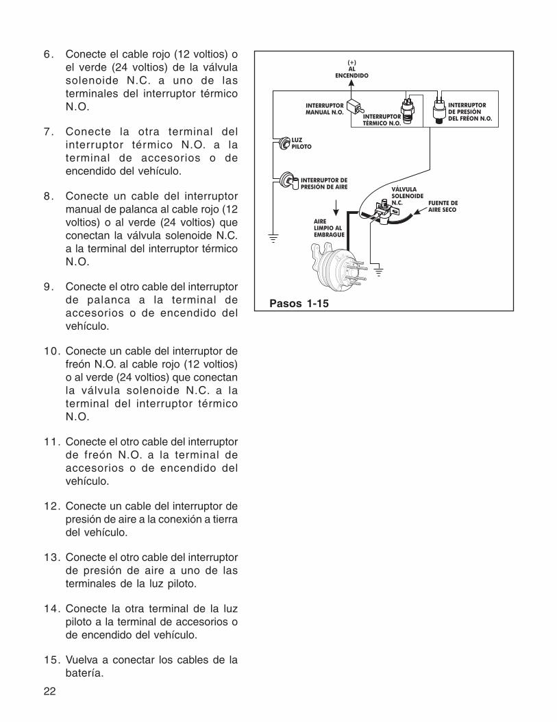
6. Conecte el cable rojo (12 voltios) oel verde (24 voltios) de la válvulasolenoide N.C. a uno de lasterminales del interruptor térmicoN.O.
7. Conecte la otra terminal delinterruptor térmico N.O. a laterminal de accesorios o deencendido del vehículo.
8. Conecte un cable del interruptormanual de palanca al cable rojo (12voltios) o al verde (24 voltios) queconectan la válvula solenoide N.C.a la terminal del interruptor térmicoN.O.
9. Conecte el otro cable del interruptorde palanca a la terminal deaccesorios o de encendido delvehículo.
10. Conecte un cable del interruptor defreón N.O. al cable rojo (12 voltios)o al verde (24 voltios) que conectanla válvula solenoide N.C. a laterminal del interruptor térmicoN.O.
11. Conecte el otro cable del interruptorde freón N.O. a la terminal deaccesorios o de encendido delvehículo.
12. Conecte un cable del interruptor depresión de aire a la conexión a tierradel vehículo.
13. Conecte el otro cable del interruptorde presión de aire a uno de lasterminales de la luz piloto.
14. Conecte la otra terminal de la luzpiloto a la terminal de accesorios ode encendido del vehículo.
15. Vuelva a conectar los cables de labatería.
Pasos 1-15

23
Esp
año
l
Revisión del funcionamiento delsistema eléctrico
1. Compruebe que la temperatura delmotor esté por debajo del ajustedel interruptor térmico y ponga enmarcha el motor para que seacumule presión de aire.
2. Instale un cable de puente entrelos terminales del interruptortérmico N.O. Esto debería operarel embrague.
Mantenga las manos y herramientasalejadas de las aspas del ventilador.El embrague puede operar en formainesperada.
3. Retire el cable de puente paradescargar el aire y desconectar elembrague.
4. Repita los pasos del 1 al 3 con elinterruptor de fréon N.O.
5. Fije el interruptor de palanca enON. Esto operará el embrague yse encenderá la luz piloto. Si éstano se enciende, revise el foco y laconexión a tierra de la luz piloto.
NOTALa posición OFF es parafuncionamiento automático y la ONes para funcionamiento continuo.

24
NOTES/NOTAS

25
Esp
año
l
NOTES/NOTAS

26
NOTES/NOTAS


R
Horton, Inc.2565 Walnut St.Roseville, MN 55113651-361-64001-800-621-1320
FACTORY/FÁBRICA: Britton, SD 57430-0050
© Copyright Horton Vehicle Components, Inc., A subsidiary of Horton, Inc., 1996.All rights reserved. Printed in U.S.A.
© Copyright Horton Vehicle Components, Inc. Una subsidiaria de Horton, Inc., 1996.Todos los derechos reservados. Impreso en E.U.A.
L-22600-A-0897