Embed Size (px)
Citation preview
MEDITERRANEAN ACTION PLAN (MAP) REGIONAL MARINE POLLUTION EMERGENCY RESPONSE CENTRE FOR THE MEDITERRANEAN SEA (REMPEC)
Theory and Proactive of Foams in
Chemical Spill Response

REGIONAL MARINE POLLUTION EMERGENCY
RESPONSE CENTRE FOR THE MEDITERRANEAN SEA (REMPEC)
MEDITERRANEAN ACTION PLAN
Guide for Theory Proactive in Chemical Spill Response
Regional Information System
www.rempec.org
December 2012
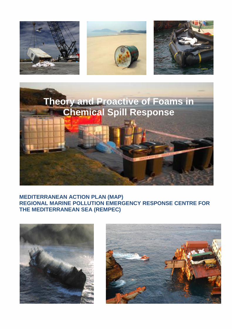
Note This document is aimed at facilitating the implementation of the “Protocol concerning Co-operation in Combating Pollution of the Mediterranean Sea by Oil and Other Harmful Substances in Cases of Emergency” of the Barcelona Convention (Emergency Protocol, 1976) and the “Protocol concerning Co-operation in Preventing Pollution from Ships and, in Cases of Emergency, Combating Pollution of the Mediterranean Sea” (Prevention and Emergency Protocol, 2002) by the Contracting Parties of the Barcelona Convention. These "Guidelines", which are advisory, do not affect in any way already existing or planned national laws and regulations related to matters covered by it. REMPEC assumes no liability whatsoever for any potentially damaging consequences which could result from the interpretation and use of information presented in this document. The designations employed and the presentation of the material in this document do not imply the expression of any opinion whatsoever on the part of IMO, UNEP, MAP and REMPEC concerning the legal status of any State, Territory, city or area, or of its authorities, or concerning the delimitation of their frontiers or boundaries. Cover photos:
1. Source 1 2. Source 2 3. Source 3 4. Source 4 5. Source 5 6. Source 6
The Guidelines are downloadable from REMPEC’s website (www.rempec.org) in the Section “RIS/Operational Guides and Technical Documents”.
For bibliographic purposes this document should be cited as follows: IMO/UNEP: Regional Information System - Operational Guides and Technical Documents - Guide for Theory Practice of Foams in Chemical Spill Response, REMPEC, December 2012.
TABLE OF CONTENTS
INTRODUCTION ................................................................................................................................. 1 I. THE FUNDAMENTAL OF A FOAM ................................................................................................ 2 II. FOAM CONCENTRATES .............................................................................................................. 4 2.1. Basic Qualities ........................................................................................................................... 4 2.2 Composition of Foams ................................................................................................................ 5 2.3. Classification of a foam concentrates ........................................................................................ 5 (a) Protection (P) Foams .......................................................................................................... 5 (b) Fluoroprotein (FP) Foams ................................................................................................... 5 (c) Synthetic (S) Foams ............................................................................................................ 5 (d) Film-forming Foams............................................................................................................. 6 (i) Aqueous Film –Foaming Foams (AFFF) ....................................................................... 6 (ii) Film-Forming Fluoroprotein Foams (FFFP) ................................................................... 6 (e) Universal (alcohol) resistant Foams (AR) ........................................................................... 6 (f) Hazmat Foams ..................................................................................................................... 6 4. Compatibility of a Foam ............................................................................................................. 7 III. PRODUCTION OF A FINISHED FOAM ...................................................................................... 7 1. Categories of a Finished Foam .................................................................................................. 7 2. Foam-making equipment ........................................................................................................... 9 IV. APPLICATION OF A FINISHED FOAM .................................................................................... 14 1. Method of Application .............................................................................................................. 14 2. Rate of Application of a Foam ................................................................................................. 15 3. Rate of supply according to the IBC Code ............................................................................. 15 CONCLUSION ................................................................................................................................ 16 ANNEX I Matric of foam capabilities to suppress/minimize the release of toxic or flammable vapour from spilled chemicals ANNEX II Calculation of the rate of supply of a foam solution for a chemical tanker of 10, 000 DWT. ANNEX III Common terminology associated with foam use
INTRODUCTION
Depending on the circumstances, a ship carrying a hazardous material, whether packaged or in bulk is faced with the possibility of a spill on board, land or into the sea. Such hazardous material spills could create environmental and public health hazards. Response to a hazardous spill is likely to involve many different response actions, sometimes used in isolation but more often used in combination. Fire considerably complicates response to a spillage and can hamper a response operation. Although it is recognized that water is the most available fire-fighting agent in a maritime environment, it is sometimes possible that response personnel have a choice in the extinguishing agent for combating fires. Foams have primarily been used as extinguishing agents for certain flammable liquids. Due to the formation of a continuous layer of small bubbles or a thin film they are able to function as a blanketing agent and as a result have also been used to suppress vapour release from certain volatile liquids. Thus, one way of decreasing the source strength of a spilled volatile liquid is to apply spray foam to its surface. This document entitled "The Theory and Practice of Foams in Chemical Spill Response" has been prepared by the Regional Marine Pollution Emergency Response Centre for the Mediterranean Sea (REMPEC). The main body of the document is a synopsis of the subject matter and is aimed at providing those involved in response operations with background information on the various technicalities associated with the use of foam as a response method. It consists of four main sections:
Section I deals with the fundamentals of a foam;
Section II deals with foam concentrates;
Section III deals with the production of a finished foam; and
Section IV deals with the application of a finished foam.
Various Annexes have also been included, one of which (Annex III) lists common terminology associated with foam use .
RIS/D/7 – Theory and practice of foams in chemicals Page 1
THEORY AND PRACTICE OF FOAMS IN CHEMICAL SPILL RESPONSE CHEMICAL EMERGENCIES
INTRODUCTION
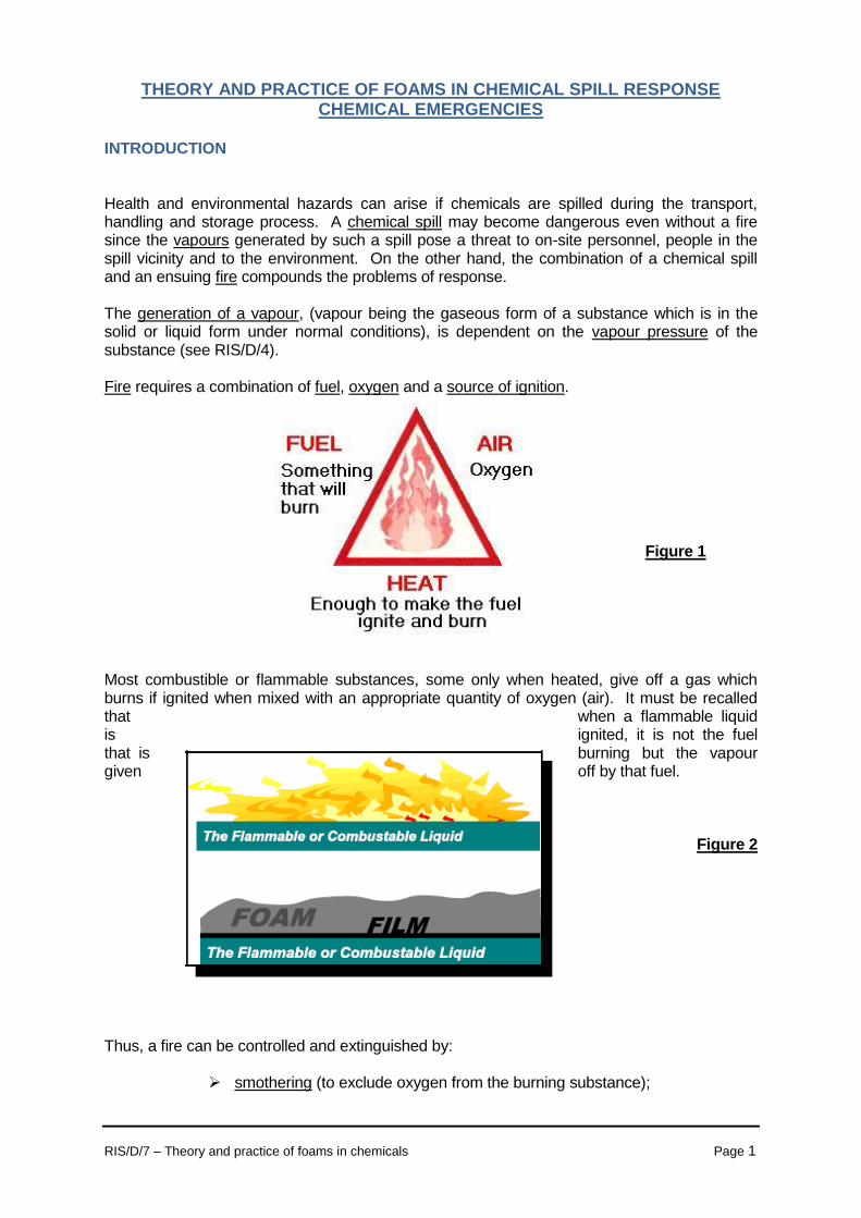
Health and environmental hazards can arise if chemicals are spilled during the transport, handling and storage process. A chemical spill may become dangerous even without a fire since the vapours generated by such a spill pose a threat to on-site personnel, people in the spill vicinity and to the environment. On the other hand, the combination of a chemical spill and an ensuing fire compounds the problems of response. The generation of a vapour, (vapour being the gaseous form of a substance which is in the solid or liquid form under normal conditions), is dependent on the vapour pressure of the substance (see RIS/D/4). Fire requires a combination of fuel, oxygen and a source of ignition.
Figure 1 Most combustible or flammable substances, some only when heated, give off a gas which burns if ignited when mixed with an appropriate quantity of oxygen (air). It must be recalled that when a flammable liquid is ignited, it is not the fuel that is burning but the vapour given off by that fuel.
Figure 2 Thus, a fire can be controlled and extinguished by:
smothering (to exclude oxygen from the burning substance);

RIS/D/7 – Theory and practice of foams in chemicals Page 2
starvation (to remove the burning fuel from the fire); and cooling (to reduce the temperature of the burning substance below the ignition temperature).
Figure 3 Foams have been particularly successful on fires because, by forming a foam blanket they can:
temporarily reduce the vapour concentration above the spill surface; decrease the evaporation rate; provide a barrier to thermal or solar radiation; inhibit ignition or flame propagation if ignition does occur; and allow gentle application of water.
The use of a foam in vapour mitigation stems from the ability of a foam cover to block vapour release, hindering evaporation of the spilled material with the overall effect of decreasing the source strength of the spill. As a general rule, foams are used on fires originating from flammable liquids or liquefiable solids. However some foams are not intended for use on fires under any circumstances and only are of use for vapour suppression. I. THE FUNDAMENTAL OF FOAM Finished foam is a mixture of three components: foam concentrate, also known as foam compound which essentially is a mixture of ingredients (see Section II), water and air (see Figure 4 below). Without any one of these components, finished foam cannot be produced. + + =
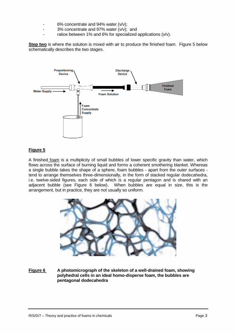
Figure 4 Components of a finished foam Two inter-related steps are involved in the production of a finished foam. Step one is where water and foam concentrate are mixed to produce the solution. There are two main ratios used when inducting (mixing) foam compound with water:
COMPOUND WATER
AIR FOAM
RIS/D/7 – Theory and practice of foams in chemicals Page 3
- 6% concentrate and 94% water (v/v); - 3% concentrate and 97% water (v/v); and - ratios between 1% and 6% for specialized applications (v/v). Step two is where the solution is mixed with air to produce the finished foam. Figure 5 below schematically describes the two stages.
Figure 5 A finished foam is a multiplicity of small bubbles of lower specific gravity than water, which flows across the surface of burning liquid and forms a coherent smothering blanket. Whereas a single bubble takes the shape of a sphere, foam bubbles - apart from the outer surfaces - tend to arrange themselves three-dimensionally, in the form of stacked regular dodecahedra, i.e. twelve-sided figures, each side of which is a regular pentagon and is shared with an adjacent bubble (see Figure 6 below). When bubbles are equal in size, this is the arrangement, but in practice, they are not usually so uniform. Figure 6 A photomicrograph of the skeleton of a well-drained foam, showing
polyhedral cells in an ideal homo-disperse foam, the bubbles are pentagonal dodecahedra
RIS/D/7 – Theory and practice of foams in chemicals Page 4
In addition, a foam must have stability, that is, the foam produced must have some elasticity which means that as it thins and stretches, there must be some restoring force generated by the stretching process which opposes this effect and prevents the stretching from continuing with eventual rupture of the foam. Before choosing a foam, certain information has to be known such as:
- the principal flammable liquid(s) requiring protection; - foam concentrate type (and costs); - foam solution application rates; and - system components required to generate the appropriate finished foam such as:
proportional (inductor) - mixes the water and foam;
foam generator (foam-making branch) - mixes air into the foam solution. II. FOAM CONCENTRATES 2.1 Basic qualities Ideally, when one chooses a foam, it should be suitable for both vapour suppression and fire fighting. Such a dual function is dependant on seven basic qualities:
Cohesion: the foam must be such that the foam bubbles cling together and form a tough cohesive blanket;
Vapour suppression: the foam must be capable of suppressing flammable or toxic
vapours;
Stability/water retention: it must have the ability to retain water in order to perform its cooling function in the case of a fire-fighting application or to maintain a vapour suppressing blanket for as long as possible in the case of a toxic spill;
Heat resistance: the foam must be able to resist the destructive effects of heat radiated
from any remaining fire or hot objects. In addition, it must be able to form an effective seal against any hot metal surfaces such as a storage tank wall;
Flowability: in order to extinguish a fire or cover a spill rapidly, the foam must flow
freely around any obstructions present in the hazard;
Fuel resistance: a good foam exhibits fuel tolerance and the ability to minimize fuel pick-up so that the foam does not get saturated and burn in the case of a fire-fighting foam;
Chemical resistance: it is important that a foam for vapour suppression of a toxic spill
can resist the detrimental chemical effects of the spilt liquid as long as possible. 2.2 Composition of foams A foam concentrate is a complex mixture of ingredients consisting of a concentrated aqueous solution of foaming agents, surfactants and various additives, all of which do not necessarily have to be present to form a foam concentrate. A number of foam concentrates are available on the market. In addition to their ability to produce foam, other properties should be taken into consideration notably those which can cause health and environmental effects. What must be noted is that there is no non-destructive method for testing the performance of foam and a user of foam is to a large extent dependent on the technical know-how and quality assurance of the manufacturer.
RIS/D/7 – Theory and practice of foams in chemicals Page 5
2.3 Classification of foam concentrates Foam concentrates are classified according to their chemical constituents. The most common types of foams are:
Protein (P) Foams; Fluoroprotein (FP) Foams; Synthetic (S) Foams; Film-Forming (F) Foams; Aqueous Film-Forming Foams (AFFF); Film-Forming Fluoroprotein Foams (FFFP);
- Universal (alcohol) resistant (AR) Foams; and - "Hazmat" Foams.
a) Protein (P) Foams These are produced by the hydrolysis of waste protein material with certain salts
added to improve stability and storage. They are usually manufactured for use at 3% and 6% concentrations, and the foam produced is:
very stable; slow for knock-down i.e. (relatively slow-flowing with a high shear stress); good burn-back resistance i.e. (good ability of the foam blanket to resist direct
flame impingement); not very resistant to chemicals; and inexpensive.
b) Fluoroprotein (FP) Foams These are formed by adding special fluorochemical surfactants to a protein
concentrate and are usually available for use at 3% and 6% concentrations. Like protein foams they do not exhibit good chemical resistance to toxic spills but have the following improved characteristics compared with protein foams such as:
flow more quickly across the fuel surface; lower shear stress; better oleophobic properties; faster fire knock-down; superior seal ability; better burn-back resistance; and increased extinguishability.
c) Synthetic (S) Foams These are based on a mixture of synthetic foaming agents (synthetic detergents) with
additional stabilizers. They are used at 1% to 6% concentrations. Synthetic foams are characterized by the following features:
flow more freely than protein foams; have a tendency to mix with the fuel; have a poor burn-back resistance; facility of using less concentrate than a protein-based foam to produce the
same expansion ratio; and poor resistance to chemicals.
RIS/D/7 – Theory and practice of foams in chemicals Page 6
d) Film-Forming Foams These concentrates produce a foam which has the ability to form a thin transparent film
over the surface of the fuel, which helps to prevent re-ignition. There are two types of film-forming foams.
(i) Aqueous Film-Forming Foams (AFFF)
These are a combination of fluorocarbon surfactants or other synthetic foaming agents and stabilizers used at concentrations of 1%, 3% and 6%. The characteristics of AFFFs are:
more fluid than P, FP or S foams; fast drainage rate (rate at which water drains from the finished foam, the liquid draining out floats on the fuel surface, thereby forming the film); effective sealing capability because of good surface tension characteristics; reasonably good burn-back resistance; do not provide long-term vapour suppression; and do not exhibit good chemical resistance.
(ii) Film-Forming Fluoroprotein Foams (FFFP)
These are a combination of protein and fluorinated surfactants and stabilizers and
used at 3% and 6% concentration. The finished foam produced has similar characteristics to AFFFs with two major advantages:
better burn-back resistance; and better knock-down.
e) Universal (alcohol) resistant (AR) Foams These are produced with foaming agents such as hydrolyzed proteins (P),
fluoroproteins (FP), synthetic stabilizers with an added polymer ingredient. These foams are formulated for use on alcohols and other polar solvents which are water-miscible. Once applied, the polar solvent spilt extracts the water from the foam blanket, the polymer additive forms a fuel-insoluble membrane at the interface between the fuel and the foam which prevents the destruction of the foam blanket. These foams can be used to suppress vapours from neutral products such as hydrocarbons and polar solvents.
f) Hazmat Foams These are specialist vapour suppression foams having good chemical resistance. Two
types are available: one suitable for alkaline material and the other for acidic material. From the above description, it is obvious that the various foams have different properties. Even when foams have similar properties, the effectiveness of these properties is not the same and the continual improvement of foam technology makes the categorization of foams according to their chemical constituents rather difficult. Thus, the above should only be taken as a guide of the properties characteristic of a specific category.
Since any degradation of the foam concentration can reduce the expansion of the finished foam, all concentrates should be stored and handled in accordance with the manufacturers' instructions. It should be borne in mind that decomposition of certain concentrates such as those which are protein based can give rise to particulate material which can ultimately cause blockage in the foam-making equipment.

RIS/D/7 – Theory and practice of foams in chemicals Page 7
2.4 Computability of a foam A whole range of commercial products are available and it is therefore important to be aware of the compatibility of foam to be used. It is always advisable to consult the manufacturers' literature and to follow recommendations given by the manufacturer. However, the following should be borne in mind:
relating to the foam itself:
different brands of concentrate liquid should not be mixed in the same equipment; the shelf life of a specific product should not have expired; there is no cross-contamination when replacing a concentrate at the preparedness
stage;
relating to the interaction of the foam with other substances:
a foam should be effective for the maximum range of cargoes, if the spill involves a mixed cargo;
information as to whether the foam concentrate is formulated for sea or fresh water or both should be available; and
ensure that the chemical involved in the spill does not react with water. III. PRODUCTION OF A FINISHED FOAM 3.1 Categories of a finished foam
When a foam concentrate is mixed with water to form a solution and aspired (if necessary), the resulting product is a mass of bubbles. However, the following parameters can be varied to produce the finished foam:
the proportion of foam concentrate mixed with water which is indicated by the manufacturer - foam solution; the volume of air mixed with a volume of foam solution - expansion ratio; and the size of the bubbles (applicable to some foams) which is determined by the
mesh or net in the foam-making equipment.
The expansion ratio of a foam is measured by comparing the weight of a known volume of finished foam with that of an equal volume of unaspirated foam solution. Based on this measurement, finished foams can be divided into four categories: Non-aspirated foams which have an expansion ratio of 0 - 2 and is produced from
standard water-delivering branches. (Non-aspirated foam category is sometimes incorporated into the LX categories below).
Low-expansion (LX) foam which has an expansion ratio of 2 - 20 and is produced by foam-making branches.
Medium-expansion (MX) foam which has an expansion ratio of 20 - 200 and is produced by foam-making branches with gauze mesh.
High-expansion (HX) foam which has an expansion ratio of 200 - 2,000 and is produced by air fans and nets.
RIS/D/7 – Theory and practice of foams in chemicals Page 8
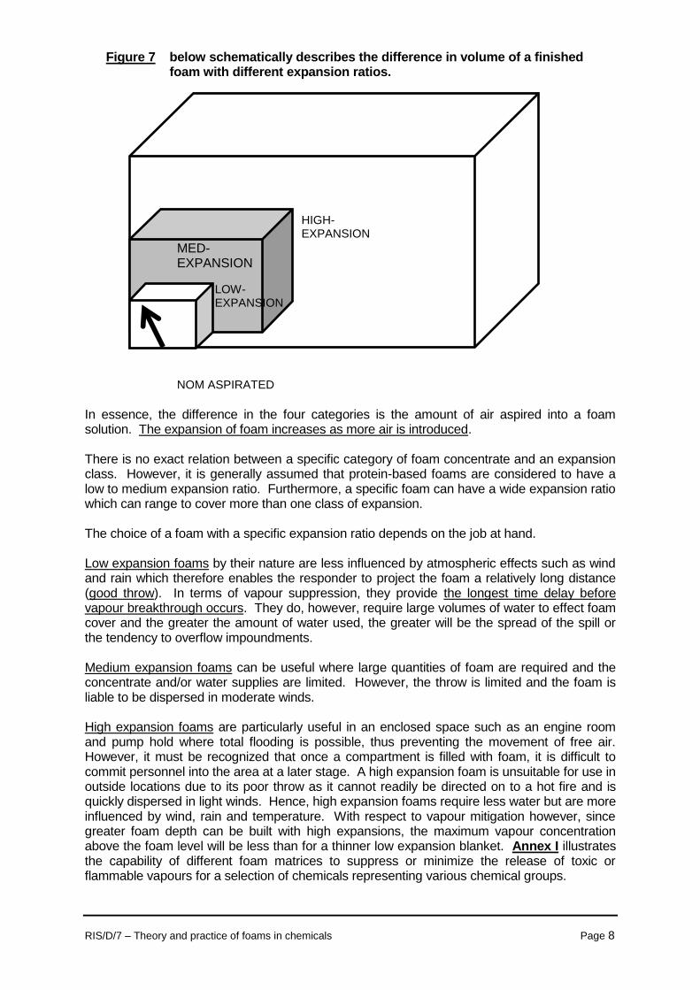
Figure 7 below schematically describes the difference in volume of a finished foam with different expansion ratios.
In essence, the difference in the four categories is the amount of air aspired into a foam solution. The expansion of foam increases as more air is introduced. There is no exact relation between a specific category of foam concentrate and an expansion class. However, it is generally assumed that protein-based foams are considered to have a low to medium expansion ratio. Furthermore, a specific foam can have a wide expansion ratio which can range to cover more than one class of expansion. The choice of a foam with a specific expansion ratio depends on the job at hand. Low expansion foams by their nature are less influenced by atmospheric effects such as wind and rain which therefore enables the responder to project the foam a relatively long distance (good throw). In terms of vapour suppression, they provide the longest time delay before vapour breakthrough occurs. They do, however, require large volumes of water to effect foam cover and the greater the amount of water used, the greater will be the spread of the spill or the tendency to overflow impoundments. Medium expansion foams can be useful where large quantities of foam are required and the concentrate and/or water supplies are limited. However, the throw is limited and the foam is liable to be dispersed in moderate winds. High expansion foams are particularly useful in an enclosed space such as an engine room and pump hold where total flooding is possible, thus preventing the movement of free air. However, it must be recognized that once a compartment is filled with foam, it is difficult to commit personnel into the area at a later stage. A high expansion foam is unsuitable for use in outside locations due to its poor throw as it cannot readily be directed on to a hot fire and is quickly dispersed in light winds. Hence, high expansion foams require less water but are more influenced by wind, rain and temperature. With respect to vapour mitigation however, since greater foam depth can be built with high expansions, the maximum vapour concentration above the foam level will be less than for a thinner low expansion blanket. Annex I illustrates the capability of different foam matrices to suppress or minimize the release of toxic or flammable vapours for a selection of chemicals representing various chemical groups.
HIGH-EXPANSION
MED-EXPANSION
LOW- EXPANSION
NOM ASPIRATED
RIS/D/7 – Theory and practice of foams in chemicals Page 9
3.2 Foam-making equipment The production of a suitable foam of constant texture depends on the mixing of water and foam and the mixing of air into the foam solution in constant proportions. The simplest possible way of mixing foam concentrate with the water is by having an in-line inductor which picks up the concentrate and introduces it into the water stream. What is of decisive importance is to ensure that the flow rate through the inductor matches that of the foam generator since a mismatch will cause a build-up of back pressure which can result in damage to the equipment. The water/foam mixture produced in this way is converted into foam in foam generators. Foam generators can be of two types:
portable (hand-held or mobile-wheeled) foam-making equipment such as:
Low Expansion foam-making branches; Medium Expansion generators; High Expansion generators.
fixed foam-making equipment such as:
base injection; foam spray; foam pourer; foam sprinklers; and foam monitors
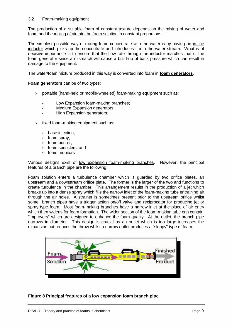
Various designs exist of low expansion foam-making branches. However, the principal features of a branch pipe are the following: Foam solution enters a turbulence chamber which is guarded by two orifice plates, an upstream and a downstream orifice plate. The former is the larger of the two and functions to create turbulence in the chamber. This arrangement results in the production of a jet which breaks up into a dense spray which fills the narrow inlet of the foam-making tube entraining air through the air holes. A strainer is sometimes present prior to the upstream orifice whilst some branch pipes have a trigger action on/off valve and reciprocator for producing jet or spray type foam. Most foam-making branches have a narrow inlet at the place of air entry which then widens for foam formation. The wider section of the foam-making tube can contain "improvers" which are designed to enhance the foam quality. At the outlet, the branch pipe narrows in diameter. This design is crucial as an outlet which is too large increases the expansion but reduces the throw whilst a narrow outlet produces a "sloppy" type of foam.
Figure 8 Principal features of a low expansion foam branch pipe
RIS/D/7 – Theory and practice of foams in chemicals Page 10
Accessory nozzles consisting of adjustable blades filled within the nozzle can sometimes be found in some branch pipes. This arrangement overcomes the tendency for a low expansion foam to remain as a cohesive "rope" type foam stream. Some branch pipes are designed to operate in a self-inducing configuration, thus by-passing the need for in-line inductors in the system. Medium foam-making branch pipes (generators) are light, convenient, compact and permit very manoeuvrable and effective operation making them ideal for fast foam cover over a large area. Various designs exist, however, the essential features of a medium foam-making branch pipe are:
foam barrel; handle; foam mesh and filter; nozzle; and pressure gauge.
Low-Expansion Foam through a Hose Line
Medium Expansion Foam System Discharge
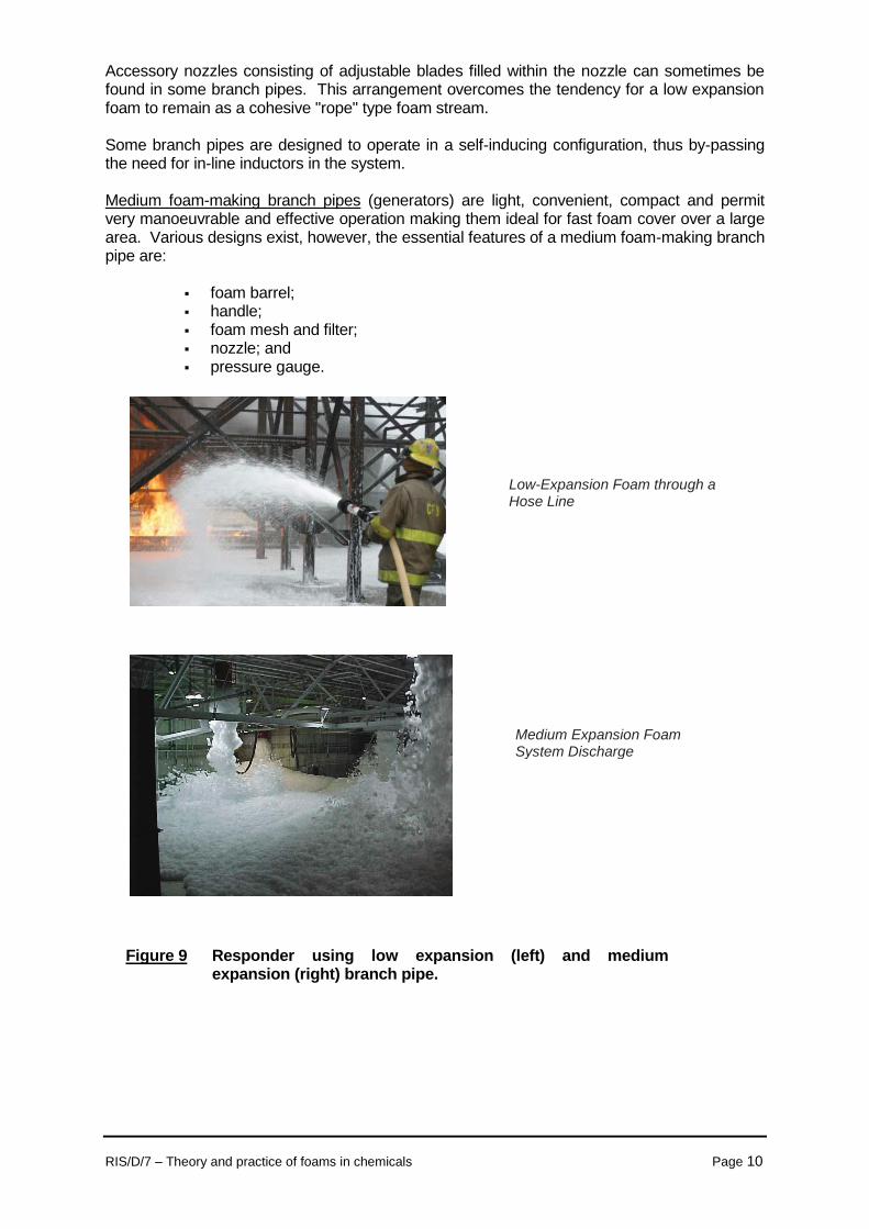
Figure 9 Responder using low expansion (left) and medium expansion (right) branch pipe.
RIS/D/7 – Theory and practice of foams in chemicals Page 11
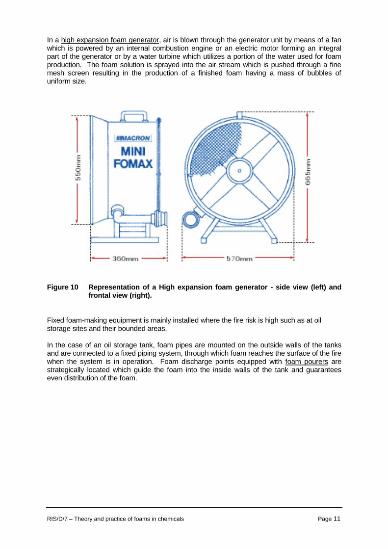
In a high expansion foam generator, air is blown through the generator unit by means of a fan which is powered by an internal combustion engine or an electric motor forming an integral part of the generator or by a water turbine which utilizes a portion of the water used for foam production. The foam solution is sprayed into the air stream which is pushed through a fine mesh screen resulting in the production of a finished foam having a mass of bubbles of uniform size.
Figure 10 Representation of a High expansion foam generator - side view (left) and frontal view (right).
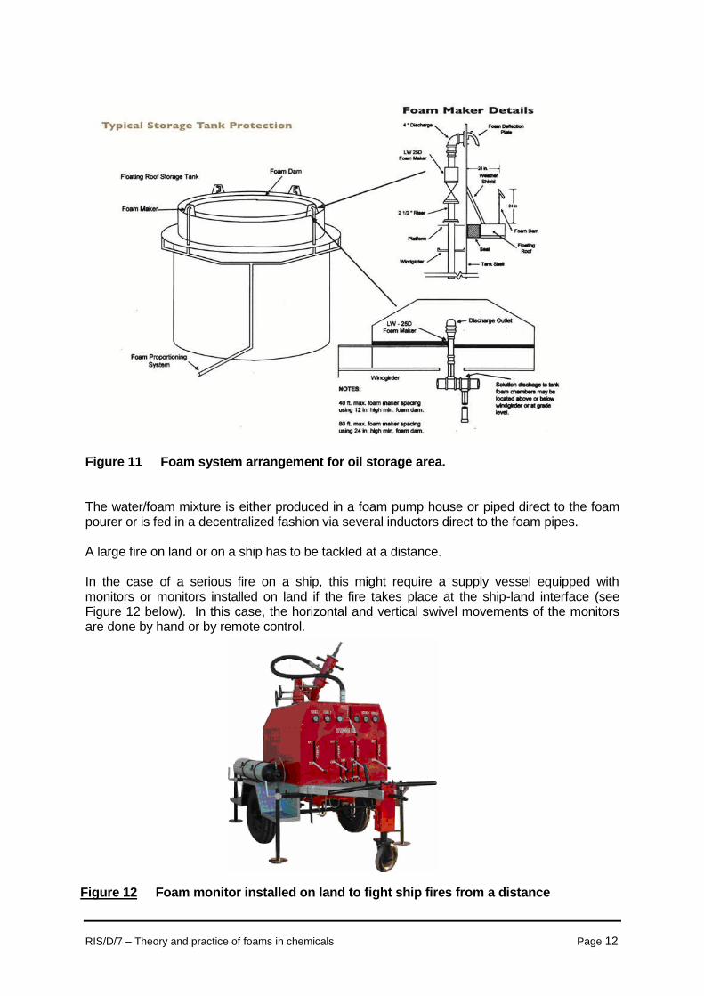
Fixed foam-making equipment is mainly installed where the fire risk is high such as at oil storage sites and their bounded areas. In the case of an oil storage tank, foam pipes are mounted on the outside walls of the tanks and are connected to a fixed piping system, through which foam reaches the surface of the fire when the system is in operation. Foam discharge points equipped with foam pourers are strategically located which guide the foam into the inside walls of the tank and guarantees even distribution of the foam.
RIS/D/7 – Theory and practice of foams in chemicals Page 12
Figure 11 Foam system arrangement for oil storage area. The water/foam mixture is either produced in a foam pump house or piped direct to the foam pourer or is fed in a decentralized fashion via several inductors direct to the foam pipes. A large fire on land or on a ship has to be tackled at a distance. In the case of a serious fire on a ship, this might require a supply vessel equipped with monitors or monitors installed on land if the fire takes place at the ship-land interface (see Figure 12 below). In this case, the horizontal and vertical swivel movements of the monitors are done by hand or by remote control.
Figure 12 Foam monitor installed on land to fight ship fires from a distance
RIS/D/7 – Theory and practice of foams in chemicals Page 13
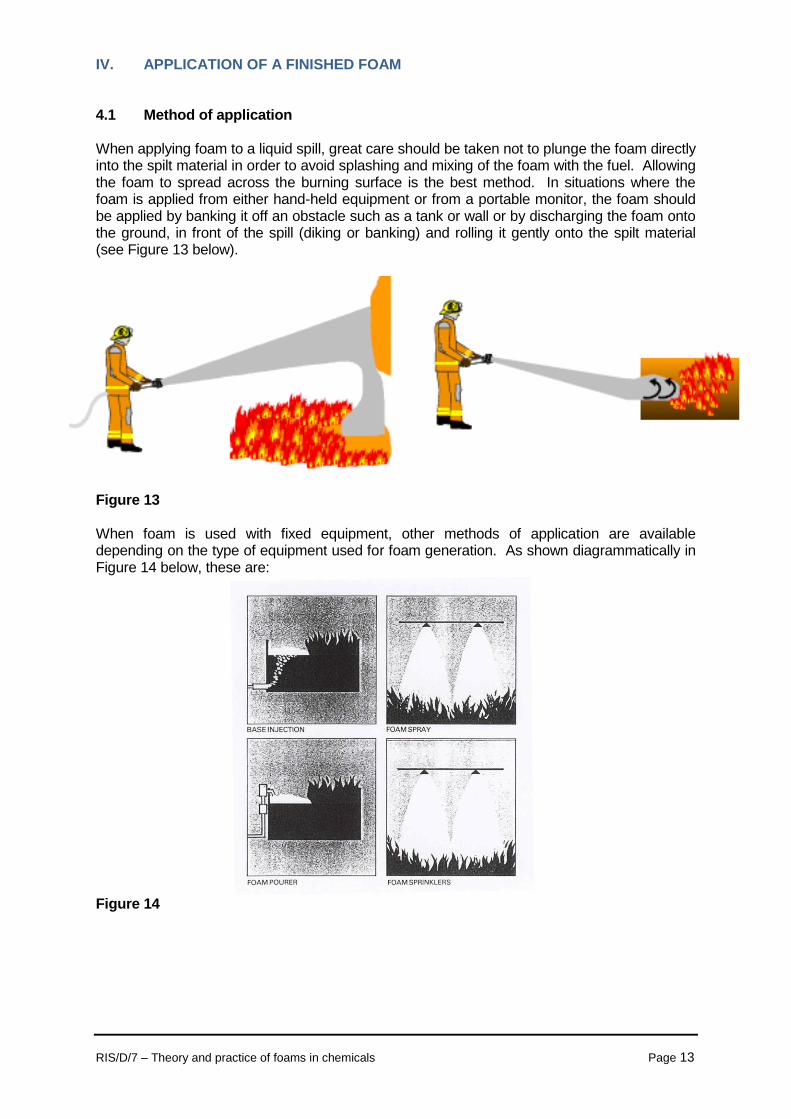
IV. APPLICATION OF A FINISHED FOAM 4.1 Method of application When applying foam to a liquid spill, great care should be taken not to plunge the foam directly into the spilt material in order to avoid splashing and mixing of the foam with the fuel. Allowing the foam to spread across the burning surface is the best method. In situations where the foam is applied from either hand-held equipment or from a portable monitor, the foam should be applied by banking it off an obstacle such as a tank or wall or by discharging the foam onto the ground, in front of the spill (diking or banking) and rolling it gently onto the spilt material (see Figure 13 below).
Figure 13 When foam is used with fixed equipment, other methods of application are available depending on the type of equipment used for foam generation. As shown diagrammatically in Figure 14 below, these are:
Figure 14

RIS/D/7 – Theory and practice of foams in chemicals Page 14
4.2 Rate of application of a foam When applying a finished foam onto a fire, there is a critical application rate which represents the absolute minimum amount of foam that is required to achieve extinction. The application rate is calculated on the solution and not on the concentrate. As shown in Figure 15 below, when the application rate falls below the critical rate, the fire is unlikely to be extinguished whilst past the critical rate is an optimum area of application which is two to three times that of the critical rate and is also termed the minimum rate of application. The use of higher application rates above the critical rate does not decrease the time taken to extinguish a fire. The minimum rate of application depends on the type (contained or free-flowing) and of the risk involved, the type of foam and method of application.
Figure 15 4.3 Rate of supply according to the IBC-Code The International Code for the Construction of Equipment of Ships carrying Dangerous Chemicals in Bulk (IBC Code) which describes the deck foam system of chemical tankers stipulates that such a system should be capable of delivering foam to the entire cargo tanks deck area as well as into any cargo tank, the deck of which is assumed to be ruptured. This information can therefore be used as a guidance for the determination of the foam supply rate in the event of fires arising from maritime accidents. According to the IBC Code, the rate of supply of foam solution should be not less than the greatest of the following:
2 litres/minute per square metre of the cargo tanks deck area, where cargo tanks deck area means the maximum breadth of the ship times the total longitudinal extent of the cargo tank spaces;
20 litres/minute per square metre of the horizontal sectional area of the single tank
having the largest such area;
10 litres/minute per square metre of the area protected by the largest monitor, such area being entirely forward of the monitor, but not less than 1,250 litres/minute. For ships of less than 4,000 tonnes deadweight, the minimum capacity of the monitor should be to the satisfaction of the Administration.
RIS/D/7 – Theory and practice of foams in chemicals Page 15
Knowing certain specificities of a ship such as the beam, length of cargo area, length of largest cargo tank and monitor spacing (proposed monitor spacing by IBC Code has been set at 9 metres), the foam supply rate for an entire cargo area of a chemical tanker can be calculated (an example of this calculation is given in Annex II). CONCLUSION
Although the above describes very simply the process how a finished foam is produced, advances have been made not only in the development of foam products themselves but in understanding the complex chemistry of foams and their performance under different fire conditions and methods of application which has warranted the development and use of particular terminology. In this regard, Annex III lists some of the common terminology associated with the use of foams. When a foam is deployed as a response method, it is usually used to combat fires arising from flammable liquid substances. However, the use of a foam has added advantages in that it reduces the amount of evaporation, and therefore can control spill vaporization. It also gives time to plan another response action. On the other hand, using a foam as a spill response method does not remove the spill from the environment. It is also difficult to use on flowing liquids and such spills have to be contained first. Finally, the fact that foams can be useful on hazardous material spills is of little value unless this information along with instructions as to what specific foam to use on each material is distributed to a response team in advance to the accident.

__________________________________________________________________________________________ RIS/D/7 – Theory and practice of foams in chemicals
ANNEX I
MATRIX OF FOAM CAPABILITIES TO SUPPRESS/MINIMIZE THE RELEASE OF TOXIC OR FLAMMABLE VAPOUR FROM SPILLED CHEMICALS
Surfactant
Low
Expansion
Surfactant
High
Expansion
Protein
Fluoro-
Protein
Alcohol
AFFF
Organics-Aromatic Hydrocarbons
- Benzene
- Tetrahydro-
naphthalene
- Toluene
C+
U
C+
B+
U
B+
B+
U
B+
B+
ND
B+
A+
ND
A+
C+
U
C+
Organics- - Cyclohexane
Alicyclics
B+
A+
B+
B+
C+
C+
Organics- - Gasoline
Industrial - Kerosene
- Naphtha
- Paint Thinner
C+
C+
C+
C+
B+
B+
B+
B+
B+
B+
B+
B+
B+
B+
B+
B+
C+
A+
C+
A+
C+
C+
C+
C+
Organics- - Liquefied Natural
Cryogens Gas
C-
A+
E-
E-
E-
E-
Inorganics
- Silicon Tetra-
chloride
- Sulphur Trioxide
E-
E-
A+
A+
E-
E-
E-
E-
E-
E-
E-
E-
Inorganics- - Ammonia
Cryogens - Chlorine
C+
C+
A+
C+
C+
C+
C+
C+
E-
E-
C+
E-
Organics-Aliphatic Hydrocarbons
Acids - Acetic Acid
- Caproic Acid
ND
U
ND
ND
ND
ND
ND
ND
ND
ND
ND
ND
Alcohols - Amyl Alcohol
- Butanol
- Butyl-Cellosolve
- Methanol
- Octanol
- Propanol
U
E-
ND
E-
U
E-
U
E-
ND
E-
U
E-
ND
E-
U
E-
U
E-
ND
E-
ND
E-
U
E-
ND
A+
ND
A+
U
A+
ND
E-
ND
E-
ND
E-
Aldehydes - Acetone
& Ketones - Methyl Butyl-
Ketone
- Methyl Ethyl-
Ketone
E-
E-
U
E-
E-
U
E-
U
U
E-
ND
ND
A+
A+
A+
E-
ND
ND
Esters - Butyl Acetate
- Ethyl Acetate
- Methyl Acrylate
- Methyl Meth-
acrylate
- Propyl Acetate
U
U
U
U
U
U
U
U
U
U
U
U
ND
ND
U
U
U
U
U
U
ND
ND
ND
ND
ND
ND
ND
ND
ND
ND
Halogenated - Butyl Bromide
- Methyl Bromide
- Tetrachloroethane
U
U
U
U
U
U
ND
ND
ND
ND
ND
ND
ND
ND
ND
ND
ND
ND
Hydrocarbons - Heptane
- Hexane
- Octane
C+
C+
C+
B+
B+
B+
B+
B+
B+
B+
B+
B+
A+
A+
A+
C+
C+
C+
Nitrogen - Dimethyl
Bearing Formamide
U
E-
ND
ND
ND
ND
* Results based on test data obtained by MSA Research Corporation for a programme sponsored by the U.S. Environmental Protection Agency - A+: Best foam formulation; B+: Next best foam formulation; C+:
Acceptable in some situations E-: Unsuitable foam formulation; U: Limited data available - capability uncertain; ND:

RIS/D/7 – Theory and practice of foams in chemicals Page 2
No data.
__________________________________________________________________________________________ RIS/D/7 – Theory and practice of foams in chemicals
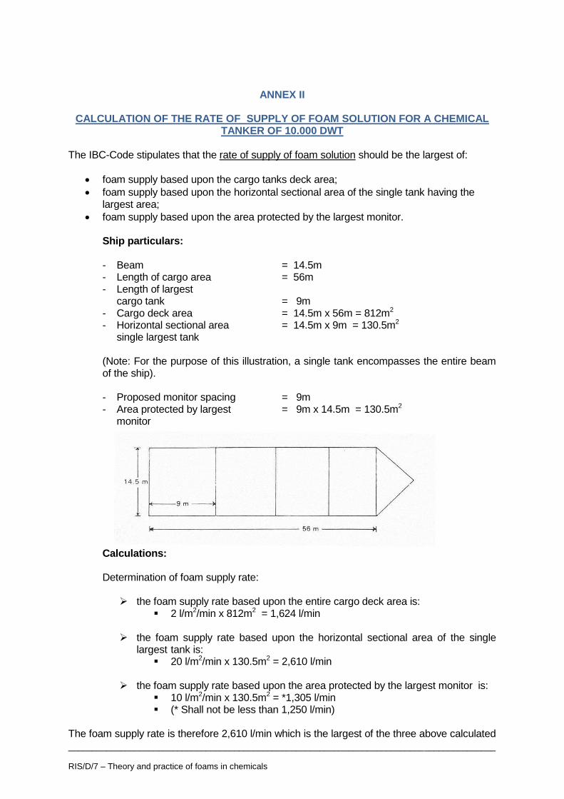
ANNEX II
CALCULATION OF THE RATE OF SUPPLY OF FOAM SOLUTION FOR A CHEMICAL TANKER OF 10.000 DWT
The IBC-Code stipulates that the rate of supply of foam solution should be the largest of:
foam supply based upon the cargo tanks deck area;
foam supply based upon the horizontal sectional area of the single tank having the largest area;
foam supply based upon the area protected by the largest monitor. Ship particulars: - Beam = 14.5m - Length of cargo area = 56m - Length of largest cargo tank = 9m - Cargo deck area = 14.5m x 56m = 812m2 - Horizontal sectional area = 14.5m x 9m = 130.5m2 single largest tank
(Note: For the purpose of this illustration, a single tank encompasses the entire beam of the ship).
- Proposed monitor spacing = 9m - Area protected by largest = 9m x 14.5m = 130.5m2 monitor Calculations: Determination of foam supply rate:
the foam supply rate based upon the entire cargo deck area is: 2 l/m2/min x 812m2 = 1,624 l/min
the foam supply rate based upon the horizontal sectional area of the single
largest tank is: 20 l/m2/min x 130.5m2 = 2,610 l/min
the foam supply rate based upon the area protected by the largest monitor is:
10 l/m2/min x 130.5m2 = *1,305 l/min (* Shall not be less than 1,250 l/min)
The foam supply rate is therefore 2,610 l/min which is the largest of the three above calculated

RIS/D/7 – Theory and practice of foams in chemicals Page 2
rates.
RIS/D/7 – Theory and practice of foams in chemicals Page 1
ANNEX III
COMMON TERMINOLOGY ASSOCIATED WITH FOAM USE
Application Rate The rate at which foam solution is applied to a fire. Usually expressed
in litres of solution per square metre of fire surface area per minute, (litres/m2/min).
AFFF Aqueous Film Forming Foam Compound. Base Injection The introduction of foam beneath the surface of certain flammable
hydrocarbons to effect extinguishment. Burn Back Resistance The ability of a foam blanket to resist direct flame impingement. Bund Area Dyke area. Class A Fires A fire in materials such as wood, paper and cloth. Class B Fires Fire involving a flammable liquid. Class C Fires Fire involving gases. Class D Fires Fire involving metals. Concentration The amount of foam compound contained in a given volume of foam
solution. The amount of foam compound actually used determines the percentage of concentration.
Critical Application Rate The lowest rate at which foam solution may be applied to a fire. Dissolved Solids Solid matter left after evaporating all water from a foam compound. Drainage Rate The rate at which water drains from a finished foam. Expansion Ratio The ratio of total finished foam volume to the volume of foam solution
from which it is made. FFFP Film-Forming Fluoroprotein Foam. Flashbacks Re-ignition of flammable liquid caused by exposure of vapours to a
source of ignition such as hot metal surface or a spark. Fluoroprotein Foam A foam compound based on hydrolised protein with surface Compound active fluorocarbon surfactants added. Finished Foam The homogeneous blanket obtained by mixing compound, water and
air consisting of an aggregate of air filled bubbles. Foam Solution The homogeneous mixture of water and concentrate (compound). Gentle Application Application of foam to the surface of a liquid fuel via a backboard, tank wall or other surface.

RIS/D/7 – Theory and practice of foams in chemicals Page 2
High Expansion Foam of expansion between 200-2000:1. Hydrocarbon Fuel Fuels containing primarily hydrogen and carbon atoms, e.g. petrol, oil,
etc. Inductor A device usually in a water line for introducing foam compound to water
to form a solution. Induction Rate The percentage of foam compound mixed or induced into the water
supply to achieve a solution. Low Expansion Foam of expansion ratios between 2 and 20:1. Medium Expansion Foam of expansion ratios between 20 and 200:1. Non aspirated Foam of expansion typically between 0-2:1. Only Film Foam Forming Compounds are suitable. Polar Solvents Generally water miscible solvents which require special foam
compounds, e.g. alcohols and ketones. Pour Point The lowest temperature at which a foam compound is fluid enough to
pour generally a few degrees above freezing point. Premix Solution A mixture of water and foam compound in correct proportions. Sediment Insoluble particles in the foam concentrate. Stability A term used with foam concentrates to determine the permanence and
security of a foam blanket. Sub-Surface Base Injection. Injection Solution Transit The time taken for the foam solution to pass from the point Time where foam compound is introduced to the water supply to where
aeration takes place.