Embed Size (px)
Citation preview

0885–3010/$25.00 © 2008 ieee
2484 ieee transactions on ultrasonics, ferroelectrics, and frequency control, vol. 55, no. 11, noVeMBer 2008
Abstract—Piezoelectric micromachined ultrasound trans-ducers (pMUTs) are a new approach for the construction of 2-D arrays for forward-looking 3-D intravascular (IVUS) and intracardiac (ICE) imaging. Two-dimensional pMUT test ar-rays containing 25 elements (5 × 5 arrays) were bulk micro-machined in silicon substrates. The devices consisted of lead zirconate titanate (PZT) thin film membranes formed by deep reactive ion etching of the silicon substrate. Element widths ranged from 50 to 200 μm with pitch from 100 to 300 μm. Acoustic transmit properties were measured in de-ionized wa-ter with a calibrated hydrophone placed at a range of 20 mm. Measured transmit frequencies for the pMUT elements ranged from 4 to 13 MHz, and mode of vibration differed for the vari-ous element sizes. Element capacitance varied from 30 to over 400 pF depending on element size and PZT thickness. Smaller element sizes generally produced higher acoustic transmit out-put as well as higher frequency than larger elements. Thicker PZT layers also produced higher transmit output per unit elec-tric field applied. Due to flexure mode operation above the PZT coercive voltage, transmit output increased nonlinearly with increased drive voltage. The pMUT arrays were attached directly to the Duke University T5 Phased Array Scanner to produce real-time pulse-echo B-mode images with the 2-D pMUT arrays.
i. introduction
real-time 3-d ultrasound imaging is becoming wide-spread in clinical use. a significant challenge is the
complexity, cost of manufacture, and limited performance of existing 2-d transducer arrays. commercial 2-d trans-ducer probes are typically limited to arrays with element pitch of approximately 300 μm and operating frequencies of less than 5 MHz. the small size of these elements dras-tically reduces the element capacitance to less than 10 pf, which leads to high source impedance and poor electrical impedance match to the system. Producing forward-look-ing 2-d arrays for catheter-based iVus imaging probes has not been achieved commercially. With catheter size of 6 to 7 french or less, the transducer array must be less than 1.5 mm in width. frequencies of 10 MHz or greater should be used for adequate resolution, and element pitch
of 100 μm or less is desirable for good array performance at these frequencies.
Micromachined ultrasound transducers (Muts) are a viable alternative to traditional lead zirconate titanate (PZt) bulk ceramic arrays, particularly for 2-d arrays. capacitive Muts (cMuts) consist of surface microma-chined membranes on silicon substrates, which produce and receive acoustic energy by electrostatic transduction [1], [2]. the primary performance advantage of cMuts is high bandwidth, often in excess of 100%; however, limita-tions include lower sensitivity and penetration depth com-pared with PZt. Manufacturability is greatly improved, because the devices are fabricated by semiconductor batch manufacturing and can even be integrated directly with integrated circuits for signal processing [3], [4].
our approach to manufacture the 2-d arrays necessary for catheter-based real-time 3-d imaging is to fabricate 2-d array piezoelectric micromachined ultrasound trans-ducers (pMuts). these devices are fabricated using well-established semiconductor manufacturing, which provides a cost-effective approach for large volume production of high-density 2-d arrays with small form factor. to date, several studies have produced limited results with pMut devices [5]–[7]; however, pulse echo operation with 2-d pMut arrays has been demonstrated only by the authors [8].
this work describes significant advances in the devel-opment of pMut devices for fine-pitch 2-d arrays. the construction of the pMut devices, theory of operation, and characterization of acoustic and electrical properties are described. initial results of ultrasonic imaging of wire phantoms at 6 to 7 MHz is also presented. these pMut arrays could enable forward-looking real-time 3-d imag-ing by providing 2-d arrays with high performance and at reasonable cost.
ii. experimental Procedure
A. Fabrication and Geometry
the pMut devices were fabricated to consist of flexible piezoelectric membranes that were bulk micromachined in 100 mm diameter silicon-on-insulator (soi) wafers. a silicon dioxide layer was thermally grown on the de-vice silicon layer, followed by electron beam evaporation of titanium and platinum thin films for the bottom elec-
Theory and Operation of 2-D Array Piezoelectric Micromachined Ultrasound
Transducersdavid e. dausch, Senior Member, IEEE, John B. castellucci, derrick r. chou, Student Member, IEEE,
and olaf t. von ramm
Manuscript received June 14, 2007; accepted June 6, 2008. d. e. dausch is with rti international, center for Materials and
electronic technologies, research triangle Park, nc (e-mail: [email protected]).
J. B. castellucci, d. r. chou, and o. t. von ramm are with duke university, center for emerging cardiovascular technologies, durham, nc.
digital object identifier 10.1109/tuffc.956
Authorized licensed use limited to: David Dausch. Downloaded on December 9, 2008 at 08:30 from IEEE Xplore. Restrictions apply.

trode. an acetate-based precursor solution [9] was then deposited by spin coating to form a PZt thin film by metallorganic decomposition at an annealing temperature of 700°c. PZt chemical composition was Pb(Zr0.53,ti0.47)o3, and film thicknesses were 1 and 2 μm. the PZt layer was photolithographically patterned and etched with a 10H2o:10Hcl:1Hf solution to form 2-d arrays with 25 elements. an interlayer dielectric was deposited and pat-terned with vias for contact to the PZt elements, followed by titanium and gold thin films deposited by electron beam evaporation and patterned by liftoff processing to form the top electrode. electrical leads were routed to the edges of the array die for wirebond connection.
following the formation of the piezoelectric elements and associated electrodes, the back sides of the soi wa-fers were photolithographically patterned, and the bulk silicon substrate was etched using a deep reactive ion etch (drie) process. the etch process terminated on the bur-ied silicon dioxide layer (1 μm thickness) of the soi wafer, thus forming a flexible membrane consisting of the elec-trodes, PZt, silicon dioxide layers, and device silicon and buried oxide layers. the device silicon layer was 5, 10, or 15 μm, yielding total pMut membrane thickness ranging from 8 to 19 μm. a schematic cross section of a pMut element is shown in fig. 1. fig. 2 shows a top view of the pMut element structure, with the PZt layer clamped by the bulk silicon substrate along 2 edges only. the drie etch cavity was rectangular in shape, extending beyond the PZt border in one axis. dimensions for the elements are listed in table i. electrode width is the top electrode width, i.e., the “active” width of the device, and is the de-scriptive dimension used for element size in this paper. el-ement pitch is center-to-center spacing, and etched length is length of the drie cavity.
drie provides anisotropic, high aspect ratio etching in silicon with vertical sidewalls, thus allowing the forma-tion of high-density 2-d arrays. Many previous efforts in pMut research have used crystallographic wet etching to form arrays [5]–[7]; however, this process limits element
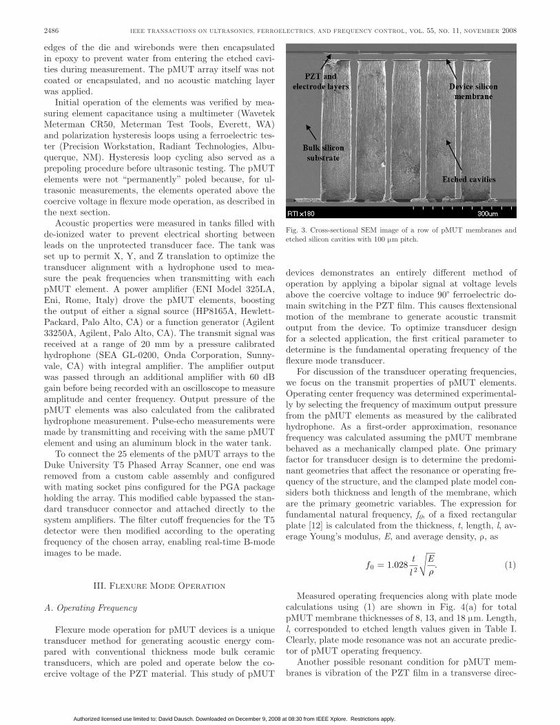
density in the arrays due to the angled etch sidewalls dic-tated by the crystallographic planes of the silicon wafer. to produce 2-d arrays that operate in the frequency range of 10 to 15 MHz, which is desirable for real-time 3-d intra-vascular imaging, element pitch on the order of 100 μm or less (less than the acoustic wavelength in tissue) is neces-sary to suppress grating lobes. Producing element pitch in this range is not possible by wet etching without thinning the silicon wafers to below the practical limit for wafer processing. other studies have used drie to etch cavities below pMut membranes [10], [11] but not as a means to produce high-density 2-d arrays. in this work, drie is critical for the fabrication of 2-d arrays that are relevant for medical imaging. a cross-sectional image obtained by scanning electron microscopy (seM) of etched pMut ele-ments with 100 μm pitch is shown in fig. 3.
B. Packaging and Measurement
following drie, the pMut wafers were diced with a dicing saw into 1 cm × 1 cm die. individual die were glued into ceramic pin grid array (PGa) packages, and the fan-out leads were wirebonded to the package. the
2485dauscH et al.: theory and operation of 2-d array piezoelectric micromachined ultrasound transducers
fig. 1. cross-sectional schematic of a pMut membrane.
fig. 2. top view layout of a pMut element showing PZt dimension as dark solid square, top electrode dimension as lighter solid square, and etched silicon cavity as dashed rectangle.
taBle i. dimensions for pMut elements,
electrode Width (μm) element Pitch(μm) etched length(μm)
50 100 6575 125 100100 150 125200 300 245
Authorized licensed use limited to: David Dausch. Downloaded on December 9, 2008 at 08:30 from IEEE Xplore. Restrictions apply.
edges of the die and wirebonds were then encapsulated in epoxy to prevent water from entering the etched cavi-ties during measurement. the pMut array itself was not coated or encapsulated, and no acoustic matching layer was applied.
initial operation of the elements was verified by mea-suring element capacitance using a multimeter (Wavetek Meterman cr50, Meterman test tools, everett, Wa) and polarization hysteresis loops using a ferroelectric tes-ter (Precision Workstation, radiant technologies, albu-querque, nM). Hysteresis loop cycling also served as a prepoling procedure before ultrasonic testing. the pMut elements were not “permanently” poled because, for ul-trasonic measurements, the elements operated above the coercive voltage in flexure mode operation, as described in the next section.
acoustic properties were measured in tanks filled with de-ionized water to prevent electrical shorting between leads on the unprotected transducer face. the tank was set up to permit X, y, and Z translation to optimize the transducer alignment with a hydrophone used to mea-sure the peak frequencies when transmitting with each pMut element. a power amplifier (eni Model 325la, eni, rome, italy) drove the pMut elements, boosting the output of either a signal source (HP8165a, Hewlett-Packard, Palo alto, ca) or a function generator (agilent 33250a, agilent, Palo alto, ca). the transmit signal was received at a range of 20 mm by a pressure calibrated hydrophone (sea Gl-0200, onda corporation, sunny-vale, ca) with integral amplifier. the amplifier output was passed through an additional amplifier with 60 dB gain before being recorded with an oscilloscope to measure amplitude and center frequency. output pressure of the pMut elements was also calculated from the calibrated hydrophone measurement. Pulse-echo measurements were made by transmitting and receiving with the same pMut element and using an aluminum block in the water tank.
to connect the 25 elements of the pMut arrays to the duke university t5 Phased array scanner, one end was removed from a custom cable assembly and configured with mating socket pins configured for the PGa package holding the array. this modified cable bypassed the stan-dard transducer connector and attached directly to the system amplifiers. the filter cutoff frequencies for the t5 detector were then modified according to the operating frequency of the chosen array, enabling real-time B-mode images to be made.
iii. flexure Mode operation
A. Operating Frequency
flexure mode operation for pMut devices is a unique transducer method for generating acoustic energy com-pared with conventional thickness mode bulk ceramic transducers, which are poled and operate below the co-ercive voltage of the PZt material. this study of pMut
devices demonstrates an entirely different method of operation by applying a bipolar signal at voltage levels above the coercive voltage to induce 90° ferroelectric do-main switching in the PZt film. this causes flextensional motion of the membrane to generate acoustic transmit output from the device. to optimize transducer design for a selected application, the first critical parameter to determine is the fundamental operating frequency of the flexure mode transducer.
for discussion of the transducer operating frequencies, we focus on the transmit properties of pMut elements. operating center frequency was determined experimental-ly by selecting the frequency of maximum output pressure from the pMut elements as measured by the calibrated hydrophone. as a first-order approximation, resonance frequency was calculated assuming the pMut membrane behaved as a mechanically clamped plate. one primary factor for transducer design is to determine the predomi-nant geometries that affect the resonance or operating fre-quency of the structure, and the clamped plate model con-siders both thickness and length of the membrane, which are the primary geometric variables. the expression for fundamental natural frequency, f0, of a fixed rectangular plate [12] is calculated from the thickness, t, length, l, av-erage young’s modulus, E, and average density, ρ, as
ft
l
E0 2
1 028= . .r
(1)
Measured operating frequencies along with plate mode calculations using (1) are shown in fig. 4(a) for total pMut membrane thicknesses of 8, 13, and 18 μm. length, l, corresponded to etched length values given in table i. clearly, plate mode resonance was not an accurate predic-tor of pMut operating frequency.
another possible resonant condition for pMut mem-branes is vibration of the PZt film in a transverse direc-
2486 ieee transactions on ultrasonics, ferroelectrics, and frequency control, vol. 55, no. 11, noVeMBer 2008
fig. 3. cross-sectional seM image of a row of pMut membranes and etched silicon cavities with 100 μm pitch.
Authorized licensed use limited to: David Dausch. Downloaded on December 9, 2008 at 08:30 from IEEE Xplore. Restrictions apply.

tion, or in the plane of the membrane, with resonance dependent on the etched length of the free membrane. this transverse resonant mode would also cause buckling and deflection of the membrane with frequency, f0, propor-tional to acoustic velocity, c, and inversely proportional to the membrane length, l, as
fcl0 2
= , (2)
which equates to
fl
E0
12
=r. (3)
as shown in fig 4(b), the transverse mode resonance calculated using (3), which is independent of membrane thickness, more accurately predicted the operating fre-quencies of the pMut membranes. it was observed that for etched membrane lengths of less than 125 μm, measured frequencies were also relatively independent of thickness; thus, the predominant geometry for predicting operating frequency was etched length.
for etched lengths of 125 μm or greater, measured fre-quencies were thickness dependent. as shown in fig. 4(c) for measured frequencies normalized to membrane thick-ness, devices with 245 μm etched length have identical f0/t values. Membranes with 125 μm etched length in the thickness range of 13 to 19 μm were also similar in f0/t value. this suggested plate mode operation according to (1); however, for larger membranes with 245 μm length, measured frequencies did not match the calculated funda-mental plate mode shown in fig. 4(a). the larger pMut membranes seemed to operate at a higher harmonic mode of the fundamental frequency [13], corresponding to either the third or fourth harmonic of the fundamental plate mode. dispersion in the f0/t values for smaller membranes (65 and 100 μm etched lengths) in fig. 4(c) confirmed that measured frequencies for these membranes were not proportional to the first order of the thickness, and were in fact thickness independent according to (3) and fig. 4(b).
the measured frequency of maximum acoustic trans-mission was higher than the theoretical fundamental plate resonance for larger pMut membranes. flexure mode op-eration above the coercive voltage involves nonlinear fer-roelectric domain switching to drive the membrane vibra-tion, and these effects are not considered for simple plate vibration. the acoustic impedance or membrane stiffness may also be different for operation at the fundamental frequency compared with harmonic frequencies. further-more, electrical impedance also changes above coercive voltage as the ferroelectric domains align. these imped-ance properties are likely to affect the operating frequency for this nonlinear system.
B. Drive Frequency
a secondary result of flex mode operation with bipolar drive is that 2 electromechanical displacement cycles are
2487dauscH et al.: theory and operation of 2-d array piezoelectric micromachined ultrasound transducers
fig. 4. operating frequencies for pMuts with different membrane thick-nesses: (a) measured frequency and calculated fundamental plate mode resonance; (b) measured frequency and calculated transverse mode reso-nance; (c) measured frequency normalized to membrane thickness.
Authorized licensed use limited to: David Dausch. Downloaded on December 9, 2008 at 08:30 from IEEE Xplore. Restrictions apply.

produced for every voltage cycle applied. the membrane position is driven primarily by expansion and contraction of the PZt film in the transverse direction (parallel to the membrane surface). Because the pMut is a unimorph structure (PZt deposited on a silicon membrane), when the PZt film attempts to contract in the transverse di-rection because of net domain alignment in the thickness direction, the membrane flexes downward. in contrast, when the PZt attempts to expand in the transverse direc-tion due to 90° domain reorientation at the coercive volt-age, the membrane flexes upward. furthermore, the same movement occurs for both signs of polarization. this effect has been observed in flextensional bulk ceramic unimorph actuators [14]. one applied sine wave cycle with frequency fin will displace the pMut membrane as shown in fig. 5. one applied voltage cycle produces 2 flexure cycles; therefore, the transmit frequency, fout, is twice the input frequency (fout = 2fin). this enables higher transducer op-erating frequency at lower drive frequency.
iV. results
A. Dielectric and Ferroelectric Properties
one of the major advantages of pMuts compared with conventional bulk ceramic transducers or cMuts is high element capacitance. this translates to significantly re-duced signal loss due to lower electrical source imped-ance. table ii lists element capacitance for different PZt thicknesses. all pMut elements were significantly higher in capacitance than typical bulk ceramic and cMut 2-d array transducers, which have element capacitance of only 1 to 10 pf, even for element widths as large as 300 μm. included in the measured values in table ii was capacitive
contribution from the on-chip electrode leads estimated as approximately 10 to 15 pf due to the interlayer dielec-tric between the leads and ground plane. for the smaller 75 μm element with lower capacitance, a measurable lin-ear component to the polarization (charge per unit area) was observed as a higher polarization-field (P-E) slope for high electric field level in the ferroelectric hysteresis loops shown in fig. 6. the larger (e.g., 200 μm) elements were less affected by the lead capacitance. However, lead capac-itance did not affect piezoelectric switching properties, as ferroelectric remanent polarization (PR) and coercive field (EC) values of 18 μc/cm2 and 40 kV/cm, respectively, were consistent for all element sizes and within each 5 × 5 array. typical percent standard deviation for satura-tion (maximum) polarization, PR and EC across a 25-ele-ment array was 0.8, 1.0, and 1.6%, respectively, indicating uniform piezoelectric activity within the PZt thin film material.
B. Transmit Properties
to correlate the transmit properties of elements with different PZt thicknesses, transmit efficiency shown in fig. 7 was calculated as a ratio of voltage received at the calibrated hydrophone, Vrx, to the electric field applied
2488 ieee transactions on ultrasonics, ferroelectrics, and frequency control, vol. 55, no. 11, noVeMBer 2008
fig. 5. schematic of pMut flexure with associated representations of input sine wave signal, ferroelectric hysteresis loop (indicating domain switching), and mechanical displacement as a function of input voltage. Points a and a’ refer to 0 V applied, points B and d refer to the coercive voltage, and points c and e refer to maximum applied voltage.
taBle ii. Measured capacitance of pMut elements.
electrode Width (μm)
capacitance (pf)
1 μm PZt thickness 2 μm PZt thickness
50 44 2975 83 48100 122 74200 446 242
fig. 6. ferroelectric polarization hysteresis loops measured at 1 kHz.
Authorized licensed use limited to: David Dausch. Downloaded on December 9, 2008 at 08:30 from IEEE Xplore. Restrictions apply.

to the element, Etx = Vtx/t. for initial comparisons, all pMut elements regardless of PZt thickness were oper-ated at approximately the same applied voltage of 25 to 30 V peak-to-peak (Vpp). for thinner membrane thick-nesses, transmit efficiencies were higher for smaller pMut elements. additionally, elements with thicker PZt films provided higher output per unit electric field applied. ef-ficiency decreased for the 75 and 100 μm elements; howev-er, for 200 μm elements with 4× greater element area than 100 μm elements, efficiency was higher. it is interesting to note that 50 μm elements produced equivalent efficiencies compared with 200 μm elements. thus, when designing pMut arrays for applications where larger elements are allowed, the optimal design would be multiple smaller ele-ments connected in parallel for greater transmit output, and this would also provide higher operating frequency.
as a function of silicon membrane thickness, transmit efficiency increased as membrane thickness (i.e., stiffness) increased from 5 to 10 μm in figs. 7(a) and 7(b), respec-tively. However, the 50 and 75 μm elements became in-creasingly damped by thicker membranes as evident in the drop in efficiency in fig. 7(c) with the 15 μm silicon thick-ness. increased applied voltage also increased transmit ef-ficiency and output pressure as shown in fig. 8. unlike conventional bulk transducers, which operate below the coercive voltage of the PZt layer, flexure mode operation employs the domain switching regime in the PZt material by operating above the coercive voltage. thus, transmit output can be increased nonlinearly by increasing voltage above the coercive voltage until the polarization becomes saturated. for pMut design and performance optimiza-tion, it is clear that higher applied transmit voltage will improve acoustic energy output. output pressure as high as 340 Pa/V was measured from a single 75 μm pMut el-ement operating at 8.6 MHz at 20 mm range in the water tank. for comparison, a commercial 2-d bulk ceramic ar-
2489dauscH et al.: theory and operation of 2-d array piezoelectric micromachined ultrasound transducers
fig 7. transmit (tx) efficiencies of pMut elements driven at 25–30Vpp for PZt thicknesses of 1 and 2 μm and device silicon thicknesses of (a) 5 μm, (b) 10 μm, and (c) 15 μm. transmit efficiency was calculated as corrected voltage received at the hydrophone divided by applied electric field (VRx/ETx).
fig. 8. transmit output pressure per unit applied voltage for a 75 μm pMut single element operating at 8.6 MHz with 2 μm PZt thickness and 10 μm device silicon thickness.
Authorized licensed use limited to: David Dausch. Downloaded on December 9, 2008 at 08:30 from IEEE Xplore. Restrictions apply.

ray element (350 μm element pitch, 3.5 MHz, from Volu-metrics Medical imaging, Hillsborough, nc) was measured at the same distance and produced 382 Pa/V. PZt 1.5-d array elements operating at 2.25 MHz have also been re-ported with output pressure of 116 Pa/V at a distance of 4 mm [15]. although these are rough comparisons, it is evident that pMut devices can provide output pressure that is comparable to conventional PZt 2-d array ceramic transducers but with smaller element size, lower source impedance, and at higher frequency.
C. Pulse-Echo Imaging Characteristics
Pulse-echo response is shown in fig. 9(a) for a 75 μm pMut element operating at 7.1 MHz. the measured pulse was generated by transmitting and receiving on the same pMut element, reflecting off an aluminum block at 20 mm range in the water tank. the pulse-echo fractional bandwidth of the frequency spectrum generated by fast fourier transform (fft), shown in fig. 9(b), was 57% at
−6 dB. uniformity of the 25 elements within each array was characterized by the standard deviation of operating frequency and transmit output. standard deviation aver-aged 3% for operating frequency and 16% for transmit output for all arrays in this study. interelement crosstalk averaged −45 dB with standard deviation of 2%.
Pulse-echo B-mode images are shown in fig. 10. these images were taken in real time using a 25-element 2-d array with 200 μm elements operating at 6.25 MHz. the target was a set of 3 metal wires spaced 5 mm apart, and images were obtained at ranges of 15 and 20 mm. Grat-ing lobe effects are noted at the image edges due to the large element pitch (300 μm). resolution was also limited due to the small aperture size (1.4 mm) and small num-ber of elements (25) in the array. to show the potential of pMut arrays, we produced a synthetic aperture im-age equivalent to a 20 × 5 element array. the pulse-echo synthetic aperture image shown in fig. 11 was generated with 100 elements using a 5 × 5 pMut 2-d array with 75
2490 ieee transactions on ultrasonics, ferroelectrics, and frequency control, vol. 55, no. 11, noVeMBer 2008
fig. 9. (a) Pulse-echo response at 7.1 MHz and (b) fft bandwidth plot for a 75 μm pMut single element with 1 μm PZt thickness and 10 μm silicon thickness driven at 27.6 Vpp.
fig. 10. B-Mode images of a 3-wire target using a 25-element array with 200 μm element width, 1 μm PZt, and 5 μm silicon thicknesses. op-erating frequency was 6.25 MHz. target range was (a) 15 mm and (b) 20 mm, respectively, in a water tank. target spacing was 5 mm.
Authorized licensed use limited to: David Dausch. Downloaded on December 9, 2008 at 08:30 from IEEE Xplore. Restrictions apply.

μm elements. to produce this image, the pMut array was driven at a lower frequency of 7.2 MHz due to the upper frequency limit of the t5 system. a 4.7 MHz high pass fil-ter and apodization of 50% were used. the 2.45 mm syn-thetic aperture with finer pitch elements produced greatly improved target resolution, and element pitch of 125 μm was significantly less than the acoustic wavelength, which eliminated grating lobes.
V. conclusions
two-dimensional pMut arrays are a promising tech-nology for providing forward-looking volumetric imaging inside of medical catheters. Performance characteristics were determined for pMut arrays with element sizes ranging from 50 to 200 μm. flexure mode operation was demonstrated in pMut devices for the first time by op-erating above the coercive voltage of the PZt layer, pro-ducing operating frequencies ranging from 4 to 13 MHz. the operating frequencies of larger membranes were thick-ness and length dependent, indicating fundamental plate mode vibration but at higher order harmonic frequen-cies. for pMut membranes less than 125 μm in length, operation most closely matched the transverse resonant mode where the frequencies were inversely proportional to etched length but independent of thickness. this enables thicker PZt layers to be used for greater acoustic output without affecting the operating frequency of the device. Higher frequencies can be produced by simply reducing the etched length of the pMut membrane. these mod-els are a topic of continued research and were guidelines for predicting operating frequency for the pMut devices. determining the vibrational modes for pMut membranes operated above the coercive voltage is a complex, nonlin-
ear problem, and more study is required to understand these phenomena fully.
several favorable operating characteristics were ob-served for pulse-echo imaging applications. High-element capacitance in the range of 30 to over 400 pf was mea-sured, which reduces source impedance and should mini-mize parasitic signal loss for pulse-echo imaging. transmit efficiency was found to be higher for smaller element sizes, enabling high performance arrays with tighter element pitch, which is critical for catheter-based 3-d probes. ar-rays with larger element size can be optimized by tiling multiple smaller elements together. acoustic pressure out-put of up to 340 Pa/V was measured for individual pMut elements operating at 8.6 MHz, which was comparable to bulk ceramic PZt transducer elements but with smaller pMut element size and higher operating frequency com-pared with bulk PZt. Pulse-echo fractional bandwidth of over 50% was measured with 8.4 MHz center frequency for 75 μm pMut elements. finally, real-time pulse-echo B-mode imaging was demonstrated for a 2-d 5 × 5 pMut array with 300 μm element pitch operating at 6.25 MHz. improved resolution and elimination of grating lobes was achieved in pulse-echo images with a 20 × 5 synthetic array possessing 125 μm element pitch and operating at 7.2 MHz.
references
[1] o. oralkan, a. s. ergun, c.-H. cheng, J. a. Johnson, M. Karaman, t. H. lee, and B. t. Khuri-yakub, “Volumetric ultrasound imaging using 2-d cMut arrays,” IEEE Trans. Ultrason. Ferroelectr. Freq. Control, vol. 50, no. 11, pp. 1581–1594, 2003.
[2] d. M. Mills, “Medical imaging with capacitive micromachined ultra-sound transducer (cMut) arrays,” in Proc. IEEE Ultrasonics Symp., 2004, pp. 384–390.
[3] c. daft, s. calmes, d. da Graca, K. Patel, P. Wagner, and i. lada-baum, “Microfabricated ultrasonic transducers monolithically inte-grated with high voltage electronics,” in Proc. IEEE Ultrasonics Symp., 2004, pp. 493–496.
[4] X. Zhuang, a. s. ergun, y. Huang, i. o. Wygant, o. oralkan, and B. t. Khuri-yakub, “integration of trench-isolated through-wafer interconnects with 2-d capacitive micromachined ultrasonic trans-ducer arrays,” Sens. Actuators A, doi:10.1016/j.sna.2007.04.008, 2007.
[5] f. akasheh, t. Myers, J. d. fraser, s. Bose, and a. Bandyopadhyay, “development of piezoelectric micromachined ultrasonic transduc-ers,” Sens. Actuators A, vol. 111, pp. 275–287, 2004.
[6] J. J. Bernstein, s. l. finberg, K. Houston, l. c. niles, H. d. chen, l. e. cross, K. K. li, and K. udayakumar, “Microma-chined high frequency ferroelectric sonar transducers,” IEEE Trans. Ultrason. Ferroelectr. Freq. Control, vol. 44, no. 5, pp. 960–969, 1997.
[7] G. Percin and B. Khuri-yakub, “Piezoelectrically actuated flexten-sional micromachined ultrasound transducers – ii. fabrication and experiments,” IEEE Trans. Ultrason. Ferroelectr. Freq. Control, vol. 49, no. 5, pp. 585–595, 2002.
[8] d. e. dausch, J. B. castellucci, d. r. chou, and o. t. von ramm, “Piezoelectric micromachined ultrasound transducer (pMut) arrays for 3d imaging probes,” in Proc. IEEE Ultrasonics Symp., 2006, pp. 930–933.
[9] G. H. Haertling, “an acetate precursor process for bulk and thin film PlZt,” in Proc. IEEE 7th Int. Symp. Applied Ferroelectrics, 1990, pp. 292–295.
[10] P. Muralt, n. ledermann, J. Baborowski, a. Barzegar, s. Gentil, B. Belgacem, s. Petitgrand, a. Bosseboeuf, and n. seter, “Piezoelectric micromachined ultrasonic transducers based on PZt thin films,”
2491dauscH et al.: theory and operation of 2-d array piezoelectric micromachined ultrasound transducers
fig. 11. B-Mode image of a 3-wire target using a synthetic aperture 100-element array with 75 μm element width. operating frequency was 7.2 Hz. target range was 13 mm in a water tank, and target spacing was 5 mm.
Authorized licensed use limited to: David Dausch. Downloaded on December 9, 2008 at 08:30 from IEEE Xplore. Restrictions apply.

IEEE Trans. Ultrason. Ferroelectr. Freq. Control, vol. 52, no. 12, pp. 2276–2288, 2005.
[11] B. Belgacem, f. calame, and P. Muralt, “design, modeling and fabrication of piezoelectric micromachined ultasonic transducers,” in Proc. IEEE Ultrasonics Symp., 2005, pp. 483–486.
[12] l. e. Kinsler and a. r. frey, Fundamentals of Acoustics. new york: Wiley, 1950.
[13] d. a. christensen, Ultrasonic Bioinstrumentation. new york: Wiley, 1988.
[14] d. e. dausch, “asymmetric 90° domain switching in rainbow actua-tors,” Ferroelectrics, vol. 210, pp. 31–45, 1998.
[15] r. l. Goldberg, M. J. Jurgens, d. M. Mills, c. s. Henriquez, d. Vaughan, and s. W. smith, “Modeling of piezoelectric multilayer ceramics using finite element analysis,” IEEE Trans. Ultrason. Fer-roelectr. Freq. Control, vol. 44, no. 6, pp. 1204–1214, 1997.
David E. Dausch (M’05–sM’07) was born in Baltimore, Md, on May 1, 1969. He received B.s. (magna cum laude) and Ph.d. degrees in ceramic engineering from clemson university, clemson, sc, in 1991 and 1995, respectively.
from 1995 to 1997, he served as a post-doc-toral research associate for the national research council at nasa langley research center in Hampton, Va, where he studied mechanical stress effects on piezoelectric materials, electromechani-cal fatigue properties of piezoelectric actuators,
and their application in aeronautic systems. He joined the Microelec-tronics center of north carolina (Mcnc), research triangle Park, nc, as an electronic materials engineer in 1998, and then became principal research engineer and team leader of the sensors & actuators Group in 2001. He managed r&d projects for niH, darPa, nasa, and vari-ous commercial partners, performing research on electronic materials and microelectromechanical systems (MeMs) technologies and applica-tions. He joined rti international, research triangle Park, nc, with the acquisition of Mcnc’s research divisions by rti in 2005. He cur-rently serves as senior research engineer and manager of nano/MeMs technologies in the center for Materials & electronics technologies. dr. dausch has authored more than 60 technical publications and presenta-tions and holds 8 u.s. patents.
John B. Castellucci was born in englewood, nJ, on July 18, 1959. He received his B.s.e. and M.s. degrees in biomedical engineering from duke university in durham, nc, in 1981 and 1986, re-spectively.
from 1985 through 1986 he worked as a senior antenna engineer for channel Master satellite systems in smithfield, nc, designing c- and Ku-band satellite dishes. from 1986 through 1988 he worked as a senior design engineer for corazonix
corporation in oklahoma city, oK, developing signal-averaging elec-trocardiograph and cardiac output monitoring instrumentation. since then he has worked as a research associate in the diagnostic ultrasound laboratory at duke university, developing advanced ultrasonic imaging scanners and transducers. He also serves as a consultant for industry. His research interests include diagnostic imaging systems, 3-d flow mea-surement and visualization, micromachined transducers, and 2-d and high-frequency arrays.
Derrick R. Chou (s’07) was born in norman, oK, on June 20, 1981. He received the B.s. degree in biomedical engineering, electrical engineering, and computer science from duke university, dur-ham, nc, in 2003 and the M.s. degree in bio-medical engineering from duke university in 2005.
He served as a graduate student for the Bio-medical interferometry, optics, and spectroscopy laboratory, part of the fitzpatrick center for Photonics and communications systems, at duke
university from 2003 to 2005, where he studied laser scanning confocal microscopy systems. He joined the center for emerging cardiovascular technologies at duke university in 2005 where he continues his graduate work studying piezoelectric micromachined ultrasound transducers.
Olaf T. von Ramm was born in Posen, Poland, on august 16, 1943. He received B.a.sc. and M.a.sc. degrees in electrical engineering from the university of toronto, toronto, ontario, canada, in 1968 and 1970, respectively and a Ph.d. degree in biomedical engineering from duke university in durham, nc, in 1973.
dr. von ramm joined the faculty of duke uni-versity in 1974 and currently is the thomas lord professor of engineering, professor of biomedical engineering, and professor of medicine. He has
served a variety of administrative roles at duke university including director of undergraduate studies, director of graduate studies, chair of the engineering faculty council, and department representative to the university’s academic council. He is the director of the national science foundation sponsored center for emerging cardiovascular technologies. His research interests include diagnostic ultrasound imaging systems, ir imaging, medical instrumentation, and their new applications. dr. von ramm has served in consulting roles for government agencies, industry, and academia.
He is a fellow of the american institute of ultrasound in Medicine, the american society of echocardiography, and the american institute for Medical and Biomedical engineering. He is a 1998 computerworld smithsonian research collection awardee.
2492 ieee transactions on ultrasonics, ferroelectrics, and frequency control, vol. 55, no. 11, noVeMBer 2008
Authorized licensed use limited to: David Dausch. Downloaded on December 9, 2008 at 08:30 from IEEE Xplore. Restrictions apply.