Embed Size (px)
Citation preview

The Xerox4520/4520mpDesktop Laser Printers
User’s Guide
WUG-TITL Page -1 Black,Red,Cyan Tuesday, February 7, 1995 12:40 PM

Xerox Corporation Xerox Canada, Limited701 South Aviation Blvd. 5650 Yonge StreetEl Segundo, CA North York, Ontario90245 CanadaUSA M2M 4G7
Americas Operations Rank Xerox, Limited200 First Stamford Place ParkwayGreenwich Avenue MarlowStamford, CT Buckinghamshire06904-2343 S17 1YLUSA United Kingdom
Copyright
1994 Xerox Corporation. All Rights Reserved.
Copyright protection claimed includes all forms of matters of copyrightable materials and information now allowed by statutory or judicial law or hereinafter granted, including without limitation, material generated from the software programs which are displayed on the screen such as styles, templates, icons, screen displays, looks, etc.
Printed in France.
Xerox
, Rank Xerox, and all product names and product numbers mentioned in this publication are trademarks.
Adobe
and PostScript
are trademarks of Adobe Systems Incorporated.
TrueRes is a trademark of DP-Tek. PCL, HP, LaserJet, Intellifont, and Resolution Enhancement Technology (RET) are trademarks of Hewlett-Packard Company. IBM is a trademark of International Business Machines Corporation. Microsoft, Microsoft Windows, Microsoft Word, MS, and MS-DOS are trademarks of Microsoft Corporation. Univers is a trademark of Linotype AG or its subsidiaries. WordPerfect is a trademark of WordPerfect Corporation. Centronics is a trademark of Centronics Corporation. Macintosh and TrueType are trademarks of Apple Computer, Incorporated. OnPage is a trademark of Computer:applications, Inc. All other product names are trademarks/ tradenames of their respective owners.
PCL
and
PCL 5e
are trademarks of Hewlett Packard Company. This printer contains an emulation of the Hewlett Packard PCL 5e command language, recognizes HP PCL 5e commands, and processes these commands in a manner compatible with Hewlett Packard LaserJet printer products.
Notice
Specifications described in this publication are subject to change without notice. Use of some features may be limited by your hardware or software configuration. Contact your dealer, Xerox or Rank Xerox for details.
WUG-TITL Page 0 Black,Red Tuesday, February 7, 1995 12:40 PM

4 5 2 0 / 4 5 2 0 m p U s e r ’ s G u i d e
❖
i
Table of Contents
Chapter 1
Introduction
...................................................
1-1
Overview 1-2
Sharing the Printer 1-5
Memory Considerations 1-6
Chapter 2
Handling Paper
.............................................
2-1
Overview 2-3
Paper Input 2-4
Paper Output 2-5
Paper Specifications 2-6
Paper Trays 2-9
Optional Feeders 2-13
Summary of Paper Trays and Paper Sizes 2-17
Loading Paper 2-19
Selecting a Paper Source 2-30
Chapter 3
Using the Control Panel
..............................
3-1
Overview 3-3
Control Panel Features 3-4
Navigating the Menu System 3-8
WUG-TOC Page 1 Black,Cyan Sunday, January 22, 1995 7:27 PM

T a b l e o f C o n t e n t s
ii
❖
4 5 2 0 / 4 5 2 0 m p U s e r ’ s G u i d e
Main Menu System 3-12
Language 3-14
PCL Menu 3-15
PostScript Menu 3-29
Interface Menu 3-38
System Menu 3-59
Test Menu 3-63
Reset Menu 3-67
Printer Settings that Affect Memory 3-69
Chapter 4
Using Fonts
....................................................
4-1
Overview 4-2
Fonts Resident on the Printer 4-4
Adding Fonts 4-8
Selecting a Font 4-11
Downloading Fonts 4-12
Chapter 5
Adding Printer Options
...............................
5-1
Overview 5-2
Installing a SIMM 5-5
Installing a Font Card 5-17
Chapter 6
Maintaining the Printer
..............................
6-1
Overview 6-2
Replacing the EP Cartridge 6-3
Adjusting the Print Density 6-12
Cleaning the Printer 6-14
Transporting the Printer 6-15
Chapter 7
Troubleshooting
...........................................
7-1
Overview 7-2
Displayed Control Panel Messages 7-5
Paper Jams 7-27
WUG-TOC Page 2 Black,Cyan Sunday, January 22, 1995 7:27 PM

T a b l e o f C o n t e n t s
4 5 2 0 / 4 5 2 0 m p U s e r ’ s G u i d e
❖
iii
Printer Operational Problems 7-40
Print Quality Problems 7-43
Appendix A
Printer and Cable Specifications
..............
A-1
Printer Specifications A-2
Cable Specifications A-5
Appendix B
Printer Commands (Escape Sequences)
...
B-1
Xerox-Unique Settings B-2
PCL Printer Commands B-3
HP-GL/2 Context Printer Commands B-21
Control Codes B-25
Appendix C
I/O Port Polling
..............................................
C-1
Appendix D
Ordering Information
.................................
D-1
Printer Options D-2
Additional Order Items D-8
Appendix E
Environmental Specifications
....................
E-1
Glossary
.......................................................................
GL-1
Index
........................................................................
IX-1
WUG-TOC Page 3 Black,Cyan Sunday, January 22, 1995 7:27 PM

iv
❖
4 5 2 0 / 4 5 2 0 m p U s e r ’ s G u i d e
WUG-TOC Page 4 Black Sunday, January 22, 1995 7:27 PM

Chapter 1
C h a p t e r 1 : I n t r o d u c t i o n
❖
1-1
Introduction
Chapter 1
Overview
...............................................................................
1-2
Printer Components 1-3
Factory Settings 1-4
Sharing the Printer
...............................................................
1-5
Memory Considerations
.......................................................
1-6
WUG-CH01 Page 1 Black,Red,Cyan Sunday, January 22, 1995 7:30 PM

O v e r v i e w
1-2
❖
4 5 2 0 / 4 5 2 0 m p U s e r ’ s G u i d e
The Xerox 4520/4520mp Desktop Laser Printers offer the most cost-effective, high-performance solution to single-user or networked printing of any advanced laser printer in their class.
At 20 pages per minute, the 4520/4520mp printers provide technically advanced features to ensure the high quality Xerox printing you have come to expect:
• 800 dpi, 600 dpi, 400 dpi, and 300 dpi resolutions
• Up to 50,000 printed pages per month
• Power saver mode
• Remote User Interface (RUI)
• TrueRes for smooth edges and enhanced resolution
• Three 250-sheet input trays, including support for A3 and 11" x 17" size paper
• Optional high-capacity feeder (1500 sheets) and high-capacity envelope feeder (250 envelopes)
• Single-sheet bypass feeder (SBF) for single-sheet manual
feeding
• Optional multi-sheet bypass feeder (MBF) for small quantity specialized printing
• Memory capacity up to 52 MBytes
• Optional 125 MB Hard Disk
• PCL 5e emulation and
PostScript Level 2 PDLs (page description languages)
• Automatic switching between PCL emulation (hereinafter referred to as PCL) and PostScript (when the PostScript option is installed)
• Ethernet, LocalTalk, and Token Ring network options, each with a variety of protocols
• Printing from five simultaneously-active ports
• User installable printer and options
Overview
WUG-CH01 Page 2 Black,Red,Cyan Sunday, January 22, 1995 7:30 PM

O v e r v i e w
C h a p t e r 1 : I n t r o d u c t i o n
❖
1-3
The key printer components are called out in Figure 1.1.
Figure 1.1 Key printer parts
PrinterComponents
Power Switch
Font Card Slots
Control Panel Display
Front Output
Middle Paper Slot
Upper Paper Slot
Lower Paper Slot
Manual Feed Slot(SBF Slot)
Network Ports 1, 2 & 3
Serial Port
Parallel Port
Control Panel Cover
Top Output
Receptacle for Optional Feeders
Front View
Rear View
Power Inlet(behind panel)
WUG-CH01 Page 3 Black,Red,Cyan Sunday, January 22, 1995 7:30 PM

O v e r v i e w
1-4
❖
4 5 2 0 / 4 5 2 0 m p U s e r ’ s G u i d e
The printer is controlled by numerous settings whose values are pre-set at the factory. These values are called
factory settings
.
If the factory settings do not suit the needs of your printing environment, you can select a new setting in either of two ways:
•
Control Panel
on the printer. See
Chapter 3: Using the Control Panel
.
•
Remote User Interface
on the host computer. Refer to the
Document Services for Printing Guide
.
FactorySettings
WUG-CH01 Page 4 Black,Red,Cyan Sunday, January 22, 1995 7:30 PM

S h a r i n g t h e P r i n t e r
C h a p t e r 1 : I n t r o d u c t i o n
❖
1-5
Particular care must be taken when changing settings for a printer being shared by users such as those on a local area network (LAN). When the printer is shared, settings must accommodate the
common
needs of users.
Considerations for a networked environment include the following:
• Downloading fonts and macros by individual users may consume printer memory. The sharing of downloaded
fonts must be coordinated. See
Chapter 4: Using Fonts
,
“Downloading Fonts” (page 4-12)
.
• Switching between PCL and PostScript may purge
downloaded data. See
Chapter 3: Using the Control Panel
,
State Saving
(page 3-28) for PCL and
State Saving
(page 3-37) for PostScript.
• Changing settings for
Jam Recovery
,
Page Protection
,
State Saving
, or
Resolution
affect memory utilization. See
Chapter 3: Using the Control Panel
,
“Printer Settings that Affect Memory” (page 3-69)
.
• The type of interface. (See page 3-38,
Appendix A
, and
Appendix C
.)
•
Auto Job End
should be
On
. (See page 3-44, page 3-48, page 3-54, page 3-58.)
•
Auto Continue
should be
On
. (See page 3-61.)
LANs generally require a system or network administrator, a person who orchestrates the use of the network. Refer to the installation guide packaged with your network option for
more information.
Sharing thePrinter
WUG-CH01 Page 5 Black,Red,Cyan Sunday, January 22, 1995 7:30 PM

M e m o r y C o n s i d e r a t i o n s
1-6
❖
4 5 2 0 / 4 5 2 0 m p U s e r ’ s G u i d e
In today’s printing environments, technologies have advanced greatly but so have their corresponding memory requirements. To make use of specialized graphics features, fonts, and other applications on the market today, you may find it necessary to increase memory size.
From the factory, the 4520 is equipped with 4 MB of resident base memory. The 4520mp is equipped with 4 MB of resident
base memory plus one 4 MB SIMM (single in-line memory module) for a total of 8 MB.
Maximum memory capacity is 52 MB.
When is more memory needed?
• You receive out-of-memory error messages when printing. See
Chapter 3: Using the Control Panel
,
“Printer Settings that Affect Memory” (page 3-69)
for more information on how certain printer settings may affect memory usage and performance. See also
“Minimum
Memory Requirements” (page 3-72)
.
• You determine that expanded capability for additional fonts, more complex documents, graphics, or higher
resolution is needed. See
Chapter 4: Using Fonts
,
“Downloading Fonts” (page 4-12)
for more information on how fonts affect memory usage.
How is more memory added?
• Install a SIMM (single in-line memory module). SIMMs are small circuit boards with memory chips that can be installed on the printer controller board. See
Chapter 5: Adding Printer Options
for more information
on SIMM installation.
Installing the 125 MB hard disk option does not add memory to the printer.
MemoryConsiderations
WUG-CH01 Page 6 Black,Red,Cyan Sunday, January 22, 1995 7:30 PM

Chapter 2
C h a p t e r 2 : H a n d l i n g P a p e r
❖
2-1
Handling Paper
Chapter 2
Overview
...............................................................................
2-3
Paper Input
............................................................................
2-4
Paper Output
........................................................................
2-5
Paper Specifications
.............................................................
2-6
Weight 2-6
Dimensions 2-7
Paper Trays
............................................................................
2-9
Upper, Middle, and Lower Trays 2-10
Single-sheet Bypass Feeder (SBF) 2-12
Optional Feeders
................................................................
2-13
Multi-sheet Bypass Feeder (MBF) 2-14
High-Capacity Feeder (HCF) 2-15
High-Capacity Envelope Feeder (HCEF) 2-16
WUG-CH02 Page 1 Black,Red,Cyan Sunday, January 22, 1995 7:32 PM
2-2
❖
4 5 2 0 / 4 5 2 0 m p U s e r ’ s G u i d e
Summary of Paper Trays and Paper Sizes
.........................
2-17
Loading Paper
.....................................................................
2-19
Loading the Upper, Middle, or Lower Paper Tray 2-19
Feeding the SBF 2-24
Loading Letterhead, Pre-printed, Drilled, or Label Paper 2-27
Loading Envelopes 2-29
Selecting a Paper Source
....................................................
2-30
PCL Paper Sources 2-30
Printing a Page 2-31
Source Mapping Settings 2-33
Factory-Set Source Mapping Settings 2-35
Source Mapping Examples 2-36Example 1 2-36Example 2 2-37Example 3 2-38Example 4 2-39Example 5 2-40Example 6 2-41Example 7 2-42
WUG-CH02 Page 2 Black,Red Sunday, January 22, 1995 7:32 PM

O v e r v i e w
C h a p t e r 2 : H a n d l i n g P a p e r
❖
2-3
This chapter provides specific information on
paper handling
:
• Paper specifications
• Paper sources and paper trays
• Manual feeding and loading of paper, including letterhead, pre-printed stationery, envelopes, labels, and transparencies
• Paper source mapping
• Printing
In this guide,
paper source
refers to the slot or opening where paper enters the printer.
Paper tray
refers to the container or device that holds the paper.
Overview
Note
WUG-CH02 Page 3 Black,Red,Cyan Sunday, January 22, 1995 7:32 PM

P a p e r I n p u t
2-4
❖
4 5 2 0 / 4 5 2 0 m p U s e r ’ s G u i d e
Paper input sources are the slots or openings where paper enters the printer. As shown in Figure 2.1, the 4520/4520mp printers have
four
paper input sources: three on the front and one on the back.
Figure 2.1 Paper input sources
PaperInput
Middle Paper Source
Upper Paper Source
Lower Paper Source
Single-sheet Bypass Feeder (SBF) Paper Source
Front View
Rear View
WUG-CH02 Page 4 Black,Red,Cyan Sunday, January 22, 1995 7:32 PM

P a p e r O u t p u t
C h a p t e r 2 : H a n d l i n g P a p e r
❖
2-5
As shown in Figure 2.2, printed output is delivered face down to the
top output tray
and face up to the
front output tray
. Output capacity on top is up to 500 sheets of standard weight paper and up to 250 sheets on the front.
Figure 2.2 Output trays
The front output tray must be removed to deliver printed output to the top tray. Whenever the front tray is installed, output is delivered to it.
For optimum performance, deliver light weight paper (60 gsm/16 lbs.) and special media (transparencies, label
stock, and envelopes) to the
front
output tray.
Depending on paper weight, you may find the front output tray holds fewer than 250 sheets. Paper jams may occur if output capacity is exceeded.
PaperOutput
Top Output Tray(also known as the
HCOS: high-capacityoutput stacker, or the
face down tray)
Front Output Tray(also known as the
face up tray)
Note
!Caution
WUG-CH02 Page 5 Black,Red,Cyan Sunday, January 22, 1995 7:32 PM

P a p e r S p e c i f i c a t i o n s
2-6
❖
4 5 2 0 / 4 5 2 0 m p U s e r ’ s G u i d e
Factors such as embossing, special edges, and general paper quality affect paper handling.
Paper
weight
specifications include the following:
• Upper, middle, and lower trays support paper weights of
60 gsm (16 lb)
to
90 gsm (24 lb)
.
• Single-sheet Bypass Feeder (SBF) supports paper weights of
60 gsm (16 lb)
to
120 gsm (32 lb)
.
For optimum printer performance, it is recommended that you use paper made for laser printers and transparency film made for Xerox laser printers and copiers.
The recommended weight of envelope paper should not exceed 90 gms (24 lb) or jamming may result. Envelopes should lay flat. Do not use envelopes that are wrinkled, nicked, or damaged.
In areas of high humidity, store partially used packages of envelopes in a sealed plastic bag. Failure to do so may cause
excessive print jams and print quality problems.
Do not use envelopes having clasps, snaps, windows, or synthetic materials. Severe damage to your printer may occur.
PaperSpecifications
Weight
Note
Note
!Caution
WUG-CH02 Page 6 Black,Red,Cyan Sunday, January 22, 1995 7:32 PM

P a p e r S p e c i f i c a t i o n s
C h a p t e r 2 : H a n d l i n g P a p e r
❖
2-7
Figure 2.3 shows paper
dimensions
in millimeters and inches.
Figure 2.3 Paper dimensions
Paper Size
Dimensions
A4 210 x 297 mm8.27 x 11.69 inches
Letter 216 x 279 mm8.5 x 11 inches
B5 (ISO) 176 x 250 mm6.93 x 9.84 inches
B4 (ISO) 250 x 352 mm9.84 x 13.9 inches
Executive 184 x 267 mm7.25 x 10.5 inches
A5 148 x 210 mm5.83 x 8.27 inches
Folio 216 x 330 mm8.5 x 13 inches
Legal 216 x 356 mm8.5 x 14 inches
Ledger 279 x 432 mm11 x 17 inches
A3 297 x 420 mm11.2 x 16.4 inches
COM-10 Envelope 105 x 241 mm4.13 x 9.5 inches
DL Envelope 110 x 220 mm4.33 x 8.66 inches
C5 Envelope 162 x 229 mm6.38 x 9.02 inches
Dimensions
WUG-CH02 Page 7 Black,Red,Cyan Sunday, January 22, 1995 7:32 PM

P a p e r S p e c i f i c a t i o n s
2-8
❖
4 5 2 0 / 4 5 2 0 m p U s e r ’ s G u i d e
The Xerox printer driver supports all paper sizes in Figure 2.3. However, if you do not install—or your application does not use—the Xerox printer driver, some of these paper sizes may not be available for your use. Refer to the
Document Services for Printing Guide
for more information
on the Xerox printer driver.
Note
WUG-CH02 Page 8 Black,Red,Cyan Sunday, January 22, 1995 7:32 PM

P a p e r T r a y s
C h a p t e r 2 : H a n d l i n g P a p e r
❖
2-9
As shown in Figure 2.4, the 4520/4520mp printers are packaged with three 250-sheet paper trays and one single-sheet bypass feeder (SBF).
Figure 2.4 Input trays
Additional paper handling options are available. See
“Optional Feeders” (page 2-13)
for more information on the multi-sheet bypass feeder (MBF), the high-capacity feeder (HCF), and the high-capacity envelope feeder (HCEF).
Paper Trays
Single-sheetBypass Feeder
(SBF)Upper Paper Tray
Middle Paper Tray
Lower Paper Tray
WUG-CH02 Page 9 Black,Red,Cyan Sunday, January 22, 1995 7:32 PM

P a p e r T r a y s
2-10
❖
4 5 2 0 / 4 5 2 0 m p U s e r ’ s G u i d e
The upper, middle, and lower paper sources (page 2-4) each accommodate a 250-sheet paper tray. A 250-sheet tray may be either a fixed tray (Figure 2.5) or a universal tray (Figure 2.6).
See
“Loading the Upper, Middle, or Lower Paper Tray” (page 2-19)
for further information on the universal tray.
† Paper dimensions are listed on page 2-7.‡ Tray capacity may differ based on the weight of the paper. Maximum paper stack:
25mm/1 inch.
† Paper dimensions are listed on page 2-7.‡ Tray capacity may differ based on the weight of the paper. Maximum paper stack:
25mm/1 inch.
Figure 2.5 Fixed trays
Fixed Tray
Paper Size
†
Capacity
‡
(Sheets)
A4
A4 250
8.5 x 11
Letter (8.5 x 11) 250
A5
A5 250
8.5 x 14
Legal (8.5 x 14) 250
A3
A3 250
11 x 17
Ledger (11 x 17) 250
Figure 2.6 Universal tray
Paper Size
†
Capacity
‡
(Sheets)
A4 250
Letter (8.5 x 11) 250
Folio (8.5 x 13) 250
Legal (8.5 x 14) 250
Ledger (11 x 17) 250
A3 250
Upper, Midd e, andLower Trays
WUG-CH02 Page 10 Black,Red,Cyan Sunday, January 22, 1995 7:32 PM

P a p e r T r a y s
C h a p t e r 2 : H a n d l i n g P a p e r
❖
2-11
To use letterhead, pre-printed stationery, or drilled paper in the upper, middle, or lower tray, see Figure 2.13 (page 2-27) for paper orientation. See Figure 2.15 (page 2-29) for envelope orientation.Note
WUG-CH02 Page 11 Black,Red,Cyan Sunday, January 22, 1995 7:32 PM

P a p e r T r a y s
2-12
❖
4 5 2 0 / 4 5 2 0 m p U s e r ’ s G u i d e
The single-sheet bypass feeder (SBF) provides for
manually
feeding a single sheet of paper or labels, a single transparency, or a single envelope (See Figure 2.7).
Figure 2.7 SBF
As its name implies, the SBF bypasses the upper, middle, and lower input printing paths.
Typical uses of the SBF include printing the first page of a document on letterhead paper or pre-printed stationery, and printing any page of a document on paper of a different size, color, or other attribute. See
Figure 2.12 (page 2-26)
for
long edge
or
short edge
paper orientation.
Insert paper into the SBF only when needed. Do not store paper in the SBF. If there is paper in it, the printer will print from the SBF first, regardless of paper size.
To use letterhead, pre-printed stationery, or drilled paper in the SBF, see Figure 2.14 (page 2-28) for paper orientation. See
Figure 2.15 (page 2-29) for envelope orientation.
Single-sheetBypass Feeder
(SBF)
A4Letter (8.5 x 11)
B5 (ISO)B4 (ISO)
ExecutiveA5
Folio (8.5 x 13)Legal (8.5 x 14)
Ledger (11 x 17)A3
Com-10DLC5
TransparencyLabel sheet
Note
WUG-CH02 Page 12 Black,Red,Cyan Sunday, January 22, 1995 7:32 PM

O p t i o n a l F e e d e r s
C h a p t e r 2 : H a n d l i n g P a p e r
❖
2-13
The 4520/4520mp printers accommodate three optional feeders that attach to the SBF source:
• Multi-sheet bypass feeder (MBF). See page 2-14.
• High-capacity feeder (HCF). See page 2-15.
• High-capacity envelope feeder (HCEF). See page 2-16.
To install any of the optional feeders, you must remove the SBF. Refer to the installation instructions provided with each optional feeder.
OptionaFeeders
Note
WUG-CH02 Page 13 Black,Red,Cyan Sunday, January 22, 1995 7:32 PM

O p t i o n a l F e e d e r s
2-14
❖
4 5 2 0 / 4 5 2 0 m p U s e r ’ s G u i d e
The optional multi-sheet bypass feeder (MBF) provides for
small capacity
printing needs. The MBF holds up to 100 sheets of standard weight (80 gsm. or 20 lb.) paper.
Use only one size of paper in the MBF at one time. Do not intermix paper sizes.
Load no more than 10 sheets of either B4 (ISO), Legal, or Folio paper into the MBF at one time.
Figure 2.8 MBF
As its name implies, the MBF bypasses the upper, middle, and lower input printing paths.
A typical use for the MBF is printing documents that require special paper size, color, or other attribute.
See
Figure 2.14 (page 2-28)
for paper orientation, and
Figure 2.15 (page 2-29)
for envelope orientation.
Mu ti-sheetBypass Feeder
(MBF)
Note
A4Letter (8.5 x 11)
B5 (ISO)B4 (ISO)
ExecutiveA5
Folio (8.5 x 13)Legal (8.5 x 14)
Com-10DLC5
TransparencyLabels
WUG-CH02 Page 14 Black,Red,Cyan Sunday, January 22, 1995 7:32 PM

O p t i o n a l F e e d e r s
C h a p t e r 2 : H a n d l i n g P a p e r
❖
2-15
The optional high-capacity feeder (HCF) provides for
large volume
printing
needs. The HCF holds up to 1500 sheets of standard weight (80 gsm. or 20 lb.) paper and comes in two paper sizes:
• A4
• 8.5 x 11 (Letter)
Figure 2.9 shows an HCF with the door open and connected to the printer.
Figure 2.9 HCF
For additional information about the HCF, see page 2-17; also refer to the
HCF Installation Instructions
.
High-CapacityFeeder (HCF)
WUG-CH02 Page 15 Black,Red,Cyan Sunday, January 22, 1995 7:32 PM

O p t i o n a l F e e d e r s
2-16
❖
4 5 2 0 / 4 5 2 0 m p U s e r ’ s G u i d e
The optional high-capacity envelope feeder (HCEF) provides for
large volume envelope printing
needs. The HCEF holds up to 250 envelopes of standard weight and comes in two sizes:
• Com-10
• DL
Figure 2.10 shows an HCEF with the door open and connected to the printer.
Figure 2.10 HCEF
For additional information about the HCEF, see page 2-17 and page 2-29; also refer to the
HCEF Installation Instructions
.
High-CapacityEnvelope Feeder
(HCEF)
WUG-CH02 Page 16 Black,Red,Cyan Sunday, January 22, 1995 7:32 PM

S u m m a r y o f P a p e r T r a y s a n d P a p e r S i z e s
C h a p t e r 2 : H a n d l i n g P a p e r
❖
2-17
Figure 2.11 shows a summary of the paper accommodated by each tray or feeder. A checkmark (
✓
) indicates support for the paper size or media.
† Paper dimensions are listed on page 2-7.‡ Fixed size tray only.†† Universal tray only.
Figure 2.11 Tray and paper summary
Paper
†
Upper
Middle
Lower
SBF
MBF
HCF
HCEF
A4
✓ ✓ ✓ ✓ ✓ ✓
Letter (8.5 x 11)
✓ ✓ ✓ ✓ ✓ ✓
B5 (ISO)
✓ ✓
B4 (ISO)
✓
Executive
✓ ✓
A5
✓
‡
✓
‡
✓
‡
✓ ✓
Folio (8.5 x 13)
✓
††
✓
††
✓
††
✓ ✓
Legal (8.5 x 14)
✓ ✓ ✓ ✓ ✓
Ledger (11 x 17)
✓ ✓ ✓ ✓
A3
✓ ✓ ✓ ✓
Com-10
✓ ✓ ✓
DL
✓ ✓ ✓
C5
✓ ✓
Transparencies
✓ ✓
Labels
✓ ✓
Summary ofPaper Trays
and PaperSizes
WUG-CH02 Page 17 Black,Red,Cyan Sunday, January 22, 1995 7:32 PM

S u m m a r y o f P a p e r T r a y s a n d P a p e r S i z e s
2-18
❖
4 5 2 0 / 4 5 2 0 m p U s e r ’ s G u i d e
Only one of the SBF, MBF, HCF, or HCEF may be installed at any time. Manual single-sheet feeding is possible with the SBF, MBF and HCF, but not the HCEF.
Install the Xerox printer driver to access the entire range of PCL paper source and source mapping settings specifically designed for the 4520/4520mp printers. Refer to the
Document Services for Printing Guide
.
Note
WUG-CH02 Page 18 Black,Red,Cyan Sunday, January 22, 1995 7:32 PM

L o a d i n g P a p e r
C h a p t e r 2 : H a n d l i n g P a p e r
❖
2-19
To load paper into the upper, middle, or lower paper tray, follow the steps below.
1
Remove the tray from the printer.
Place the tray on a flat surface.
Loading Paper
Loading the Upper,Middle, or Lower
Paper Tray
WUG-CH02 Page 19 Black,Red,Cyan Sunday, January 22, 1995 7:32 PM

L o a d i n g P a p e r
2-20
❖
4 5 2 0 / 4 5 2 0 m p U s e r ’ s G u i d e
2
Remove the tray cover.
3
If loading the universal tray, adjust the end and side guides to the desired paper size.
Paper sizes are marked on the bottom of the universal tray.
See
Figure 2.6 (page 2-10)
for universal tray information.
WUG-CH02 Page 20 Black,Red,Cyan Sunday, January 22, 1995 7:32 PM

L o a d i n g P a p e r
C h a p t e r 2 : H a n d l i n g P a p e r
❖
2-21
4
Press the bottom of the paper tray down to a locked position.
WUG-CH02 Page 21 Black,Red,Cyan Sunday, January 22, 1995 7:32 PM

L o a d i n g P a p e r
2-22
❖
4 5 2 0 / 4 5 2 0 m p U s e r ’ s G u i d e
Do not exceed the MAX fill line (shown on the label on the inside wall of
the paper tray).
5
Load paper in the tray, making sure the paper is tucked under the metal corners.
Use up to a maximum of 250 sheets, a stack less than 25 mm/ 1 inch. Do not load paper above the maximum fill marker.
If you are loading letterhead or pre-printed stationery, see page 2-27. If loading envelopes, see page 2-29.
For optimum performance, load paper with the curl side up when delivering to the front output tray (page 2-5). When delivering paper to the top output tray (page 2-5), load paper
with the curl side down.
!Caution
Note
WUG-CH02 Page 22 Black,Red,Cyan Sunday, January 22, 1995 7:32 PM

L o a d i n g P a p e r
C h a p t e r 2 : H a n d l i n g P a p e r
❖
2-23
6
Insert the tray in the printer.
WUG-CH02 Page 23 Black,Red,Cyan Sunday, January 22, 1995 7:32 PM

L o a d i n g P a p e r
2-24
❖
4 5 2 0 / 4 5 2 0 m p U s e r ’ s G u i d e
To feed paper into the SBF, follow the steps shown below.
When manually feeding paper in the Single-sheet Bypass Feeder (SBF), the Multi-sheet Bypass Feeder (MBF), or the manual tray on the High Capacity Feeder (HCF), the printer may fail to feed the sheet if the paper is removed and then reinserted before the feed mechanism begins to move the sheet. The printer may indicate
Online/Processing...
on the control panel. If this occurs, open and close the top cover, reinsert the paper in the feed slot and place the printer
Online
via the control panel.
1
Adjust the guides to the desired paper size.
Make sure the guides are snug against both sides of the sheet but not too tight as to buckle it.
See
Figure 2.7 (page 2-12)
for SBF information.
Feeding the SBF
Note
WUG-CH02 Page 24 Black,Red,Cyan Sunday, January 22, 1995 7:32 PM

L o a d i n g P a p e r
C h a p t e r 2 : H a n d l i n g P a p e r
❖
2-25
2
Insert only one sheet of paper, pre-printed stationery, transparency, label paper, or envelope at a time into the SBF.
If you are feeding letterhead, pre-printed stationery, or drilled paper, see page 2-27. See page 2-29 for envelopes.
For best performance:
a
Stand facing the SBF straight on.
b
Refer to Figure 2.12 (page 2-26) for the proper paper orientation (long edge or short edge first).
c
Insert the sheet, guided by the side guides, at a steady rate.
d
Continue to insert the sheet until the lead edge of the sheet makes contact and a slight buckle forms.
e
To assure that the sheet is being introduced without skew, apply pressure first on one side of the sheet and then the other such that the entire lead edge of the sheet makes full contact.
f
Maintain slight pressure on the sheet until the printer begins to pull in the sheet.
WUG-CH02 Page 25 Black,Red,Cyan Sunday, January 22, 1995 7:32 PM

L o a d i n g P a p e r
2-26
❖
4 5 2 0 / 4 5 2 0 m p U s e r ’ s G u i d e
Figure 2.12 shows SBF paper orientation. To print properly, paper is inserted either long edge or short edge first.
The SBF guides indicate in a general way where to position the paper. All sizes are centered in the SBF.
If you are experiencing skew on the output, review the instructions above and be sure each step is being followed; check to be sure that the entire lead edge of the sheet has bottomed out (the sheet should have a slight buckle along the entire width).
Figure 2.12 Long or short edge paper orientation
Paper Size
Long or Short Edge First
A4 Long
Letter (8.5 x 11) Long
B5 (ISO) Long
B4 (ISO) Short
Executive Long
A5 Long
Folio (8.5 x 13) Short
Legal (8.5 x 14) Short
Ledger (11 x 17) Short
A3 Short
Com-10 Short
DL Short
C5 Short
Note
WUG-CH02 Page 26 Black,Red,Cyan Sunday, January 22, 1995 7:32 PM

L o a d i n g P a p e r
C h a p t e r 2 : H a n d l i n g P a p e r
❖
2-27
Figure 2.13 illustrates the paper orientation needed to print letterhead, pre-printed stationery, or drilled paper in the upper, middle, or lower tray. (Labels are not supported in these trays. See Figure 2.14, page 2-28.)
Figure 2.13 Loading letterhead, pre-printed stationery, or drilled paper in the upper, middle, or lower tray
Of course, you may need to adjust your software application’s printing margins to:
• Prevent overwriting the letterhead or pre-printed images.
• Prevent overwriting the drilled holes.
LoadingLetterhead,Pre-printed,
Drilled, or LabelPaper
(face down)
WUG-CH02 Page 27 Black,Red,Cyan Sunday, January 22, 1995 7:32 PM

L o a d i n g P a p e r
2-28
❖
4 5 2 0 / 4 5 2 0 m p U s e r ’ s G u i d e
Figure 2.14 illustrates paper orientation in the SBF and MBF.
Figure 2.14 Loading letterhead, pre-printed stationery, drilled, or label paper in the SBF or MBF
Label
paper may be loaded in the
SBF
or
MBF
only.
For optimum performance, use A4 or Letter size label paper.
For additional
SBF
information, see page 2-12, page 2-17, and page 2-24. For more about the
MBF
, see page 2-14 and page 2-17; also refer to the
MBF Installation Instructions
.
(face up)
Note
WUG-CH02 Page 28 Black,Red,Cyan Sunday, January 22, 1995 7:32 PM

L o a d i n g P a p e r
C h a p t e r 2 : H a n d l i n g P a p e r
❖
2-29
Figure 2.15 illustrates the envelope orientation needed to print COM-10, DL, or C5 envelopes.
Figure 2.15 Loading envelopes
1. Adjust the guides to the desired envelope size.
Make sure that they are snug against both sides of the envelope but not too tight as to buckle it.
2. Insert only one envelope at a time into the SBF.
For best performance:
— Stand facing the SBF straight on.
— Insert the envelope (refer to Figure 2.15), guided by the side guides, at a steady rate.
— Continue to insert the envelope until its lead edge makes contact and a slight buckle forms. Apply pressure first on one side of the envelope and then the other so that the lead edge makes full contact.
— Maintain slight pressure on the envelope until the printer begins to pull in the envelope.
To print envelopes, use the
high-capacity envelope feeder (HCEF), SBF
, or
MBF
only.
LoadingEnvelopes
Note
WUG-CH02 Page 29 Black,Red,Cyan Sunday, January 22, 1995 7:32 PM

S e l e c t i n g a P a p e r S o u r c e
2-30
❖
4 5 2 0 / 4 5 2 0 m p U s e r ’ s G u i d e
For a print job, your software application sends information, called the Printer Control Language (PCL), to the printer to communicate paper source and page size. How the printer interprets the PCL command for paper source and page size depends on the printer menu settings for
Source Mapping
and
MBF Paper Size
. If PCL commands for paper source and page size are not sent to the printer, the printer menu settings for
Paper Size
and
Default Source
are used. See
Chapter 3: Using the Control Panel
for further information on these and all PCL Menu settings (page 3-15).
PostScript functions differently than PCL. Refer to the PostScript Installation Instructions for more information.
Paper source
is a term that describes the tray, feeder, or slot from which the printer feeds paper.
PCL, and therefore your printer, recognizes the six paper sources shown in Figure 2.16, which may, or may not, appear in your software application.
Figure 2.16 Six PCL paper sources
PCL Paper Source
Alternate Names
Upper
Upper, Paper Tray, Paper Cassette
Manual
Manual, Manual Feed
Manual Envelope
Envelope Manual Feed
Lower
Large Capacity
Paper Deck
Envelope Feeder
Selecting aPaper Source
Note
PCL Paper Sources
WUG-CH02 Page 30 Black,Red,Cyan Sunday, January 22, 1995 7:32 PM

S e l e c t i n g a P a p e r S o u r c e
C h a p t e r 2 : H a n d l i n g P a p e r
❖
2-31
When a print job is received by the printer, the sequence to select the paper tray for each page is as follows:
1. Page size is established.
If page size is not sent by the application, the PCL Menu setting called
Paper Size
is used.
2. Paper source is established.
If a paper source is sent by the application, it will be one of the six PCL paper sources listed in Figure 2.16.
If paper source is not sent by the application, the PCL Menu setting called
Default Source
is used. Some software applications have a paper source called “Auto Select” or “Auto Sheet Feed.” When used, this results in a PCL paper source being omitted from the print job.
3. When the printer is ready to print the page, tray sequence is established.
For the paper source chosen in the second step above, a tray or sequence of trays is taken from the PCL Menu
Source Mapping
setting for that source. For settings, see
Figure 2.18 (page 2-35)
.
4. The printer searches in the tray or in any tray in the tray sequence for the correct page size from the first step above.
In a tray sequence, the trays are searched left to right as they appear in the
Source Mapping
setting. For example, for sequence Up-Mid-Low, the upper tray is searched first, the middle tray second, and the lower tray third.
5. If a tray with the correct paper size is found, the page is printed from that tray.
If no tray with the correct paper size is found, the tray sequence and paper size are displayed on the Control Panel along with a message to load the correct paper size. Printing halts.
Printing a Page
WUG-CH02 Page 31 Black,Red,Cyan Sunday, January 22, 1995 7:32 PM

S e l e c t i n g a P a p e r S o u r c e
2-32
❖
4 5 2 0 / 4 5 2 0 m p U s e r ’ s G u i d e
— Put paper of the requested size in a tray in the tray sequence and the page will be printed.
— Or, press
Enter
to print from the first tray in the tray sequence, regardless of paper size. If that tray becomes empty, the next tray with the same paper size will be used. This source and size will be used until the printer receives a new page containing a PCL paper source, page size, or reset command.
WUG-CH02 Page 32 Black,Red Sunday, January 22, 1995 7:32 PM

S e l e c t i n g a P a p e r S o u r c e
C h a p t e r 2 : H a n d l i n g P a p e r
❖
2-33
For each of the six PCL paper sources (
Figure 2.16
,
page 2-30
), a
Source Mapping
setting from Figure 2.17 is used. You may change settings depending on your printing needs. For details, see
“Factory-Set Source Mapping Settings” (page 2-35)
,
“Source Mapping Examples” (page 2-36)
, and
Source Mapping
(page 3-22)
.
Figure 2.17 Source Mapping settings
Source Mapping setting
Description
UpperMiddleLowerUpper-MiddleUpper-LowerMiddle-LowerUp-Mid-Low
Tray or tray sequence to be used for each of the six PCL paper sources.
Manual Tray selection appearing when there is no MBF, HCF, or HCEF installed.
Use this selection to print the first page of a print job by feeding a single sheet of paper into the SBF slot before the print job starts.
MBF Tray selection appearing when the MBF (page 2-14) is installed.
Source MappingSettings
WUG-CH02 Page 33 Black,Red,Cyan Sunday, January 22, 1995 7:32 PM

S e l e c t i n g a P a p e r S o u r c e
2-34
❖
4 5 2 0 / 4 5 2 0 m p U s e r ’ s G u i d e
HCEFHCEF-UpperHCEF-MiddleHCEF-LowerHCEF-Up-MidHCEF-Up-LowHCEF-Mid-LowHCEF-Up-Mid-Low
Tray or tray sequence appearing when the HCEF (page 2-16) is installed.
HCFHCF-UpperHCF-MiddleHCF-LowerHCF-Up-MidHCF-Up-LowHCF-Mid-LowHCF-Up-Mid-Low
Tray or tray sequence appearing when the HCF (page 2-15) is installed.
Figure 2.17 Source Mapping settings
(continued)
Source Mapping setting
Description
WUG-CH02 Page 34 Black,Red,Cyan Sunday, January 22, 1995 7:32 PM

S e l e c t i n g a P a p e r S o u r c e
C h a p t e r 2 : H a n d l i n g P a p e r
❖
2-35
Figure 2.18 shows the factory-set
Source Mapping
defaults for the six PCL paper sources, and how the settings change when the optional MBF, HCF, or HCEF is installed and
Reset
Menus
is implemented. See
Chapter 3: Using the Control Panel
,
“Reset Menu” (page 3-67)
.
Only one of the SBF, MBF, HCF, or HCEF may be installed at any time. Manual single-sheet feeding is possible with the SBF, MBF, and HCF, but not the HCEF.
Install the Xerox printer driver to access the entire range of PCL paper source and source mapping settings specifically designed for the 4520/4520mp printers. Refer to the
Document Services for Printing Guide
.
Figure 2.18 Factory settings for Source Mapping
PCL Paper Source
Base Model
With MBF
With HCF
With HCEF
Upper
Up-Mid-Low Up-Mid-Low HCF-Up-Mid-Low Up-Mid-Low
Manual
Manual MBF Manual HCEF
Manual Envelope
Manual MBF Manual HCEF
Lower
Lower Lower Lower Lower
Large Capacity
Up-Mid-Low Up-Mid-Low HCF Up-Mid-Low
Envelope Feeder
Manual MBF Manual HCEF
Factory-Set SourceMapping Settings
Note
WUG-CH02 Page 35 Black,Red,Cyan Sunday, January 22, 1995 7:32 PM

S e l e c t i n g a P a p e r S o u r c e
2-36
❖
4 5 2 0 / 4 5 2 0 m p U s e r ’ s G u i d e
Review the following
Source Mapping
examples to take full advantage of the 4520/4520mp capabilities.
All examples assume that
Default Source
is set to
Upper
.
You do not have a MBF or HCF installed. You want to load as much paper in the printer as possible. You use only one size of paper.
1. Load the upper, middle, and lower trays with regular paper stock.
2. Set
Source Mapping
for “Upper” to “Up-Mid-Low.”
3. In either your software application or the Xerox printer driver, set paper source to the upper tray.
The printer will pull paper from the upper tray until is it empty, then from the middle tray until it is empty, and then from the lower tray until it is empty. As soon as the upper or middle tray is reloaded, the printer will pull paper from them again.
The Source Mapping setting determines from where the printer pulls paper.
For the paper sources you intend not to use, always set Source Mapping to the same setting as that used for your regular paper stock. You will avoid unexpected results if those paper
sources are used by mistake.
The examples suggest using specific PCL paper sources but generally you may substitute any source to fit your printing needs.
Source MappingExamples
Example 1
Note
Note
WUG-CH02 Page 36 Black,Red,Cyan Sunday, January 22, 1995 7:32 PM
S e l e c t i n g a P a p e r S o u r c e
C h a p t e r 2 : H a n d l i n g P a p e r
❖
2-37
You have a HCF installed. You want to load as much paper in the printer as possible. You use only one size of paper.
1. Load the HCF, upper, middle, and lower trays with regular paper stock.
2. Set
Source Mapping
for “Upper” to “HCF-Up-Mid-Low.”
3. In either your software application or the Xerox printer driver, set paper source to the upper tray.
The printer will pull paper from the HCF until it is empty, then from the upper tray until is it empty, then from the middle tray until it is empty, and finally from the lower tray. As soon as the HCF, upper, or middle tray is reloaded, the printer will pull paper from them again.
Example 2
WUG-CH02 Page 37 Black,Red,Cyan Sunday, January 22, 1995 7:32 PM

S e l e c t i n g a P a p e r S o u r c e
2-38
❖
4 5 2 0 / 4 5 2 0 m p U s e r ’ s G u i d e
You do not have a HCF installed. You want to print mostly on Letter (8.5 x 11) paper but sometimes on Legal (8.5 x 14).
1. Load the upper and middle trays with Letter paper stock.
2. Load the lower tray with Legal paper stock.
3. Set
Source Mapping
for “Upper” to “Upper-Middle.”
4. Set
Source Mapping
for “Lower” to “Lower.”
5. In either your software application or the Xerox printer driver, set paper source to:
— Upper tray for Letter pages.
— Lower tray for Legal pages.
The printer will pull Letter paper from the upper tray until is it empty, then from the middle tray. It will pull Legal paper from the lower tray.
Alternatively, you could set
Source Mapping
for “Upper” to “Up-Mid-Low” and set your application paper source to the upper tray for both Letter and Legal pages.
The printer will automatically switch between the trays according to the paper size requested
. The disadvantage is that Control Panel messages may be misleading. Whether alerting you to load Letter or Legal paper, the Control Panel will always display “Up-Mid-Low” as the location to load that paper size. You must know which paper size goes into which tray.
Example 3
WUG-CH02 Page 38 Black,Red,Cyan Sunday, January 22, 1995 7:32 PM

S e l e c t i n g a P a p e r S o u r c e
C h a p t e r 2 : H a n d l i n g P a p e r
❖
2-39
You have a HCF installed. You want to print mostly on Letter (8.5 x 11) paper but sometimes on Legal (8.5 x 14). Some of the Legal pages need to be on color or pre-printed paper.
1. Load the HCF and middle trays with Letter paper stock.
2. Load the upper tray with white Legal paper stock.
3. Load the lower tray with color or pre-printed Legal paper.
4. Set
Source Mapping
for “Large Capacity” to “HCF-Middle.”
5. Set
Source Mapping
for “Upper” to “Upper.”
6. Set
Source Mapping
for “Lower” to “Lower.”
7. In either your software application or the Xerox printer driver, set paper source to:
— Large Capacity for Letter pages.
— Upper tray for Legal pages (white stock).
— Lower tray for Legal pages (color or pre-printed stock).
The printer will pull Letter pages from the HCF or middle tray when the HCF is empty. It will pull white Legal pages from the upper tray. It will pull color or pre-printed Legal pages from the lower tray.
Alternatively, you could set the Source Mapping for “Upper” to “HCF-Up-Mid” and set your application paper source to the upper tray for both Letter and white Legal pages.
The printer will automatically switch between the trays according to the paper size requested
. The only disadvantage is that Control Panel messages may be misleading. Whether alerting you to load Letter or Legal paper, the Control Panel will always display “HCF-Up-Mid” as the location to load that paper size. You must know which paper size goes into which tray.
Example 4
WUG-CH02 Page 39 Black,Red,Cyan Sunday, January 22, 1995 7:32 PM

S e l e c t i n g a P a p e r S o u r c e
2-40
❖
4 5 2 0 / 4 5 2 0 m p U s e r ’ s G u i d e
You do not have a MBF or HCF installed. You want to print mostly on white A4 paper but sometimes on color A4 paper. You occasionally print on DL envelopes.
1. Load the upper and middle trays with white A4 paper stock.
2. Load the lower tray with color A4 paper stock.
3. Set
Source Mapping
for “Upper” to “Upper-Middle.”
4. Set
Source Mapping
for “Lower” to “Lower.”
5. Set
Source Mapping
for “Manual” and “Manual Envelope” to “Manual.”
6. In either your software application or the Xerox printer driver, set paper source to:
— Upper tray for A4 pages (white stock).
— Lower tray for A4 pages (color stock).
— Manual for DL envelopes. (You could have also set paper source to Manual Envelope for DL envelopes.)
The printer will pull white A4 paper from the upper tray until it is empty and then from the middle tray. It will pull color A4 pages from the lower tray. For each DL envelope, the printer halts and the Control Panel displays a message requesting a DL envelope to be manually fed through the SBF. Insert one envelope into the SBF and it will feed.
Example 5
WUG-CH02 Page 40 Black,Red,Cyan Sunday, January 22, 1995 7:32 PM

S e l e c t i n g a P a p e r S o u r c e
C h a p t e r 2 : H a n d l i n g P a p e r
❖
2-41
You have a MBF installed. You want to print mostly on white A4 size paper but sometimes on DL size envelopes. Occasionally, you print on color A4 size paper.
1. Load the upper and middle trays with white A4 paper stock.
2. Load the lower tray with color A4 paper stock.
3. Load the MBF with DL envelopes.
4. Set
Source Mapping
for “Upper” to “Upper-Middle.”
5. Set
Source Mapping
for “Lower” to “Lower.”
6. Set
Source Mapping
for “Manual” and “Manual Envelope” to “MBF.”
7. Set
MBF Paper Size
to “DL.”
8. In either your software application or the Xerox printer driver, set paper source to:
— Upper tray for A4 pages (white stock).
— Lower tray for A4 pages (color stock).
— Manual for DL envelopes. (You could have also set paper source to Manual Envelope for DL envelopes.)
The printer will pull white A4 paper from the upper tray until it is empty, then from the middle tray. It will pull color A4 pages from the lower tray. It will pull DL envelopes from the MBF.
Example 6
WUG-CH02 Page 41 Black,Red,Cyan Sunday, January 22, 1995 7:32 PM

S e l e c t i n g a P a p e r S o u r c e
2-42
❖
4 5 2 0 / 4 5 2 0 m p U s e r ’ s G u i d e
You do not have a MBF or HCF installed. You want to use pre-printed stationery for the first page and regular stock for the other pages of your document. Your software application has the capability to ask for the first page of a document from a different source than the rest of the document. (The Xerox PCL 5e emulation Windows printer driver also has this capability.) It is assumed your pre-printed stationery is the same size as your regular stock.
1. Load the upper and middle trays with the regular paper stock.
2. Load the lower tray with the pre-printed stationery.
3. Set
Source Mapping
for “Upper” to “Upper-Middle.”
4. Set
Source Mapping
for “Lower” to “Lower.”
5. In either your software application or the Xerox PCL 5e emulation Windows printer driver, set paper source for the first page to Lower and set paper source for the remaining pages to Upper.
The printer will pull the first page from the lower tray and all other pages from the upper then middle trays.
Example 7
WUG-CH02 Page 42 Black,Red,Cyan Sunday, January 22, 1995 7:32 PM

Chapter 3
C h a p t e r 3 : U s i n g t h e C o n t r o l P a n e l
❖
3-1
Using the Control Panel
Chapter 3
Overview
...............................................................................
3-3
Control Panel Features
.........................................................
3-4
The Display 3-4
The Keys 3-5
Navigating the Menu System
..............................................
3-8
Menu System Indicators 3-9
Setting a Menu Option 3-10
Main Menu System
.............................................................
3-12
Language
.............................................................................
3-14
Language Options 3-14
PCL Menu
............................................................................
3-15
PCL Menu Hierarchy 3-15
PCL Menu Options 3-18
WUG-CH03 Page 1 Black,Red,Cyan Tuesday, March 21, 1995 4:54 PM

3-2
❖
4 5 2 0 / 4 5 2 0 m p U s e r ’ s G u i d e
PostScript Menu
..................................................................
3-29
PostScript Menu Hierarchy 3-30
PostScript Menu Options 3-32
Interface Menu
...................................................................
3-38
Interface Menu Hierarchy 3-38
Parallel Menu Options 3-42
Serial Menu Options 3-46
LocalTalk Menu Option 3-51
Ethernet Menu Options 3-52
Token Ring Menu Options 3-55
System Menu
......................................................................
3-59
System Menu Hierarchy 3-59
System Menu Options 3-60
Test Menu
............................................................................
3-63
Test Menu Hierarchy 3-63
Test Menu Functions 3-64
Reset Menu
.........................................................................
3-67
Reset Menu Hierarchy 3-67
Reset Menu Functions 3-67
Printer Settings that Affect Memory
.................................
3-69
Minimum Memory Requirements 3-72
WUG-CH03 Page 2 Black,Red Tuesday, March 21, 1995 4:54 PM

O v e r v i e w
C h a p t e r 3 : U s i n g t h e C o n t r o l P a n e l
❖
3-3
Shown in Figure 3.1, the Control Panel is both informative and interactive. Not only does it display status and user actions required, the Control Panel also enables you to change printer settings to control how the 4520/4520mp printer operates in your environment.
Figure 3.1 Control Panel
This chapter describes the following:
• Control Panel display and keys
• Control Panel menu selections
• Guidelines for configuring the printer to meet your printing needs
Overview
WUG-CH03 Page 3 Black,Red,Cyan Tuesday, March 21, 1995 4:54 PM
C o n t r o l P a n e l F e a t u r e s
3-4
❖
4 5 2 0 / 4 5 2 0 m p U s e r ’ s G u i d e
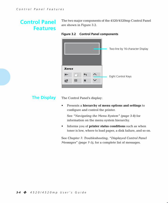
The two major components of the 4520/4520mp Control Panel are shown in Figure 3.2.
Figure 3.2 Control Panel components
The Control Panel’s display:
• Presents a
hierarchy of menu options and settings
to configure and control the printer.
See
“Navigating the Menu System” (page 3-8)
for information on the menu system hierarchy.
• Informs you of
printer status conditions
such as when toner is low, where to load paper, a disk failure, and so on.
See
Chapter 7: Troubleshooting,
“Displayed Control Panel Messages” (page 7-5),
for a complete list of messages.
Control PanelFeatures
Two-line by 16-character Display
Eight Control Keys
The Display
WUG-CH03 Page 4 Black,Red,Cyan Tuesday, March 21, 1995 4:54 PM

C o n t r o l P a n e l F e a t u r e s
C h a p t e r 3 : U s i n g t h e C o n t r o l P a n e l
❖
3-5
As described in Figure 3.3, the Control Panel keypad consists of
eight
keys, identified as international symbols and labeled in English.
Figure 3.3 Control Panel keys and their functions
Key
Description
Online
Toggles between
online
and
offline
.
When online, the printer is able to receive and print pages.
When offline, page processing and printing halts, but the printer is still able to respond to status requests. You must take the printer
offline
to:
• Access the menu system with
Menu
or
Reset
• Insert or remove a font card.
• Perform tasks such as forcing a form feed for a partially printed page.
The printer goes offline automatically when it has a fault condition such as a paper jam or an open cover. Use
Online
to put the printer back online after correcting such conditions.
The online message indicates a “closed” switch; that is, printing continues:
Online ___
The offline message indicates an “open” switch; that is, printing halts:
Offline _/_
Reset
Displays the Reset Menu and the first function:
Reset Printer
.
Press
Up
or
Down
repeatedly to step through the other Reset Menu functions one at a time. See
“Reset Menu” (page 3-67)
.
The printer must be offline for
Reset
to function.
Form Feed
Prints a partial page if one exists in the printer.
It does not send a blank sheet of paper through the printer.
The printer must be offline for
Form Feed
to function.
Form Feed
only works in PCL mode, not in PostScript. See
“PCL Menu” (page 3-15)
for more information.
Menu
Displays the Main Menu and the first submenu:
Language
.
The printer must be offline for
Menu
to function.
In any submenu, press
Menu
to take you to the top of the Main Menu. See
“Main Menu System” (page 3-12)
for a full description.
The Keys
WUG-CH03 Page 5 Black,Red,Cyan Tuesday, March 21, 1995 4:54 PM

C o n t r o l P a n e l F e a t u r e s
3-6
❖
4 5 2 0 / 4 5 2 0 m p U s e r ’ s G u i d e
Esc
In the menu system, exits the current menu level and returns to the previous one.
Press
Esc
at any time in the menu system to take you to the previous level. No changes to values will be saved unless you first press
Enter
Press
Esc
while at Reset Menu or the top level of Main Menu to exit either menu.
Enter
In the menu system, accesses, sets, or invokes the displayed submenu, value, or function.
• When a submenu is displayed, press
Enter
to access a submenu.
• When a printer setting is displayed, such as
Copies
, press
Enter
to set the current value as the default value.
• In PCL, press
Enter
to override a paper mismatch.
• When a printer action is displayed, such as any of the Test Menu (page 3-63) or Reset Menu (page 3-67) functions, press
Enter
to invoke the action.
Out of the menu system, acts as a Continue key.
• After certain error conditions when
Auto Continue
is
Off
, press
Enter
to continue the printing process. See
Auto Continue
(page 3-61) for more information.
Figure 3.3 Control Panel keys and their functions
(continued)
Key
Description
Po
WUG-CH03 Page 16 Black,Red,Cyan Tuesday, March 21, 1995 4:54 PM

C o n t r o l P a n e l F e a t u r e s
C h a p t e r 3 : U s i n g t h e C o n t r o l P a n e l
❖
3-7
Up
In the menu system, scrolls backward (up) through submenus or through the current list of values or functions.
For numeric values such as number of
Copies
, press
Up
to increase the number.
Scrolling wraps—if the first item in a list is displayed, press
Up
to display the last item in the list.
Press
Up
for more than two seconds to scroll continuously. During scrolling, there may be a greater increment for each step than that for single presses. For example, for the PCL Menu setting
Pitch
(page 3-20), the single press increment is 0.01 whereas the scrolling increment is 1.00.
When the hard disk option has been installed, press
Up
to respond to a disk failure error message. Pressing
Up
will reformat the hard disk. See
Chapter 7: Troubleshooting,
“Displayed Control Panel Messages” (page 7-5),
for more information on hard disk failure error messages.
Down
In the menu system, scrolls forward (down) through the submenus or through the current list of values or actions.
For numeric values such as number of
Copies
, press
Down
to decrease the number.
Scrolling wraps—if the last item in a list is displayed, press
Down
to display the first item in the list.
Press
Down
for more than two seconds to scroll continuously. During scrolling, there may be a greater increment for each step than that for single presses. For example, for the PCL Menu setting
Pitch
(page 3-20), the single press increment is 0.01 whereas the scrolling increment is 1.00.
When the hard disk option has been installed, press
Down
to respond to a disk failure error message. Hard disk usage will be aborted when
Down
is pressed. See
Chapter 7: Troubleshooting,
“Displayed Control Panel Messages” (page 7-5)
, for more information on hard disk failure error messages.
Figure 3.3 Control Panel keys and their functions
(continued)
Key
Description
WUG-CH03 Page 7 Black,Red,Cyan Tuesday, March 21, 1995 4:54 PM

N a v i g a t i n g t h e M e n u S y s t e m
3-8
❖
4 5 2 0 / 4 5 2 0 m p U s e r ’ s G u i d e
The 4520/4520mp Control Panel contains
two
menu structures:
•
Main Menu
and its submenus:
— Language
— PCL Menu
—
PostScript Menu
(when the PostScript option is installed)
— Interface Menu
— System Menu
— Test Menu
The
Main Menu
system is accessed by pressing
Menu
Each of the submenus may have other submenus, settings, or functions. See
“Main Menu System” (page 3-12)
for more information.
•
Reset Menu
and its functions:
— Reset Printer
— Reset Menus
— Reset All
—
Cancel PS Job
(when the PostScript option is installed)
The
Reset Menu
is accessed by pressing
Reset
There are no submenus. See
“Reset Menu” (page 3-67)
.
Take the printer
offline
(page 3-5) to access the
Main Menu
or the
Reset Menu
.
Navigating theMenu System
Note
WUG-CH03 Page 8 Black,Red,Cyan Tuesday, March 21, 1995 4:54 PM

N a v i g a t i n g t h e M e n u S y s t e m
C h a p t e r 3 : U s i n g t h e C o n t r o l P a n e l
❖
3-9
As shown in Figure 3.4, three symbols called
indicators
may appear on menu displays.
Figure 3.4 Menu indicator symbols on the Control Panel display
Symbol
Description
Example
> Indicates another
menu
level below this one.
Main MenuLanguage >
= Indicates that a value or setting follows the
option
on the bottom line.
Language =Français
* After a
setting
, indicates it is the current value.
Language =English *
Menu SystemIndicators
WUG-CH03 Page 9 Black,Red,Cyan Tuesday, March 21, 1995 4:54 PM

N a v i g a t i n g t h e M e n u S y s t e m
3-10
❖
4 5 2 0 / 4 5 2 0 m p U s e r ’ s G u i d e
To set a
Main Menu
option or to invoke a
Test Menu
or
Reset Menu
function, follow the steps below:
1
Press Online to take the printer offline.
You will see:
Offline _/_Press a key...
2
Press Menu to access the Main Menu or press Reset to access the Reset Menu.
3
Press Down or Up to scroll through the list of submenus, options, or functions.
4
When you see the submenu, option, or function you want, press Enter
If you selected a submenu or option you did not want, press
Esc
to return to the previous level, then make the selection you want and press
Enter
to accept it.
5
If necessary, repeat Step 3 and Step 4 to go through submenu levels to reach all desired options or functions.
If many possibilities exist, such as 1 through 99 for number of
Copies
, you can scroll quickly by holding down the key.
After pressing
Enter
to accept a setting, you will briefly see on the top line of the display:
* saved *
This indicates the value has been saved as the current setting.
Setting aMenu Option
WUG-CH03 Page 10 Black,Red,Cyan Tuesday, March 21, 1995 4:54 PM

N a v i g a t i n g t h e M e n u S y s t e m
C h a p t e r 3 : U s i n g t h e C o n t r o l P a n e l
❖
3-11
6
You may either continue to work in the menu system by repeating the steps above, or exit and return to normal operation by pressing Online
If you press Online before Enter the value will not be saved.
Other ways to exit a menu option or the menu system completely are as follows:
• In the Main Menu, press
Menu
to return to the top of the
Main Menu
.
• Press
Esc
from
Main Menu
or
Reset Menu
to exit the menu system and display the following message:
Offline _/_Press a key...
!Caution
WUG-CH03 Page 11 Black,Red,Cyan Tuesday, March 21, 1995 4:54 PM

M a i n M e n u S y s t e m
3-12
❖
4 5 2 0 / 4 5 2 0 m p U s e r ’ s G u i d e
The
Main Menu
system is hierarchical, based on a cascading system of submenus, each containing other submenus or options designed to configure the printer for your environment. The
Main Menu
hierarchy
is depicted in
Figure 3.5 (page 3-13)
.
In this chapter, factory settings are shown
boldfaced
and followed by an asterisk (
*
). See Chapter 1: Introduction
(page 1-4)
for a definition of factory setting.
When you change a factory setting or an existing setting to a new value, the new value becomes the
current
setting.
On the printer, the current setting always appears
first
in a list of values and is followed by an asterisk (*). The other possible values are located by pressing
Up
or
Down
to scroll through the list.
See “Reset Menu” (page 3-67) for information on how to
revert to factory settings.
Main MenuSystem
Note
WUG-CH03 Page 12 Black,Red,Cyan Tuesday, March 21, 1995 4:54 PM
M a i n M e n u S y s t e m
C h a p t e r 3 : U s i n g t h e C o n t r o l P a n e l
❖
3-13
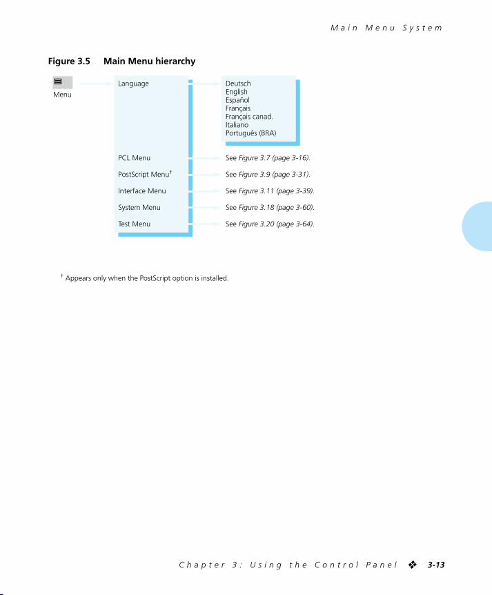
Figure 3.5 Main Menu hierarchy
Menu
Language
PCL Menu
PostScript Menu†
Interface Menu
System Menu
Test Menu
DeutschEnglishEspañolFrançaisFrançais canad.ItalianoPortuguês (BRA)
See Figure 3.7 (page 3-16).
See Figure 3.9 (page 3-31).
See Figure 3.11 (page 3-39).
See Figure 3.18 (page 3-60).
See Figure 3.20 (page 3-64).
† Appears only when the PostScript option is installed.
WUG-CH03 Page 13 Black,Red,Cyan Tuesday, March 21, 1995 4:54 PM

L a n g u a g e
3-14
❖
4 5 2 0 / 4 5 2 0 m p U s e r ’ s G u i d e
Language
includes a list of international languages used to display messages on the Control Panel and used to print text on the Configuration Sheet (page 3-64).
Figure 3.6 shows the
Language
options and their English equivalent. See
“Setting a Menu Option” (page 3-10)
for the steps to find and change the language setting.
The
Language
option is not changed by the
Reset Menus
function (page 3-67).
Figure 3.6 Language options
Option
English Equivalent
Deutsch German
English International English
Español Spanish
Français French
Français canad. French Canadian
Italiano Italian
Português (BRA) Brazilian Portuguese
Language
LanguageOptions
Note
WUG-CH03 Page 14 Black,Red,Cyan Tuesday, March 21, 1995 4:54 PM

P C L M e n u
C h a p t e r 3 : U s i n g t h e C o n t r o l P a n e l
❖
3-15
PCL Menu
options establish the
default
configuration for the printer. PCL (Printer Control Language) is used by software applications to send information and instructions to the printer.
The
PCL Menu
hierarchy
is depicted in
Figure 3.7 (page 3-16)
.
PCL Menu
PCL MenuHierarchy
WUG-CH03 Page 15 Black,Red,Cyan Tuesday, March 21, 1995 4:54 PM

P C L M e n u
3-16
❖
4 5 2 0 / 4 5 2 0 m p U s e r ’ s G u i d e
Figure 3.7 PCL Menu hierarchy showing factory settings
Internal*Upper†
Lower†
Soft†
LanguagePCL MenuPostScript Menu‡
Interface MenuSystem MenuTest Menu
Copies
Font Source
Font Number
Pitch
Point Size
Default Source
Source Mapping
Upper*ManualManual EnvelopeLowerLarge Capacity‡
Envelope Feeder‡
UpperManualManual EnvelopeLowerLarge CapacityEnvelope Feeder
1* - 99
0* - 999
.44 - 99.99 by .01(10.00*)
4.00 - 999.75 by .25(12.00*)
UpperMiddleLowerUpper-MiddleUpper-LowerMiddle-LowerUp-Mid-LowManualMBF‡
HCEF‡
HCEF-Upper‡
HCEF-Middle‡
HCEF-Lower‡
HCEF-Up-Mid‡
HCEF-Up-Low‡
HCEF-Mid-Low‡
HCEF-Up-Mid-Low‡
HCF‡
HCF-Upper‡
HCF-Middle‡
HCF-Lower‡
HCF-Up-Mid‡
HCF-Up-Low‡
HCF-Mid-Low‡
HCF-Up-Mid-Low‡
† Appears when font cards are installed or downloaded fonts are available.‡ Appears only when the option is installed.
Appears only when the default font is scalable.
Menu
WUG-CH03 Page 16 Black,Red,Cyan Tuesday, March 21, 1995 4:54 PM

P C L M e n u
C h a p t e r 3 : U s i n g t h e C o n t r o l P a n e l
❖
3-17
Figure 3.7 PCL Menu hierarchy showing factory settings
(continued)
Portrait*Landscape
Off*On
Legal (8.5x14)Folio (8.5x13)Letter (8.5x11)* (USA)A4 (210x297)* (Europe)Exec (7.25x10.5)B5 (176x250)A5 (148.5x210)Com-10DLC5
005 - 12864* (Europe)60* (USA)
Off*A4 (210x297)Legal (8.5x14)Letter (8.5x11)Ledger (11x17)A3 (297x420)
300x300600x600*400x400800x800
OffOn*
Off*On
DesktopISO L1ISO L2ISO L5ISO-4 UKISO-6 ASCIIISO-11 SwedishISO-15 ItalianISO-17 SpanishISO-21 GermanISO-60 Norw. v1ISO-69 FrenchLegalMath-8Microsoft Publ.PC-8PC-8 DNPC-8 TkPC-850PC-852Pi FontPS MathPS TextRoman-8*Ventura Int’l.Ventura MathVentura USWin 3.0Win L1Win L2Win L5
A3 (297x420)Ledger (11x17)B4 (250x352)Legal (8.5x14)Folio (8.5x13)Letter (8.5x11)* (USA)A4 (210x297)* (Europe)Exec (7.25x10.5)B5 (176x250)A5 (148.5x210)Com-10DLC5
Paper Size
MBF Paper Size
Orientation
Form Length
Symbol Set
Page Protection
Jam Recovery
Resolution
TrueRes
State Saving
WUG-CH03 Page 17 Black,Red,Cyan Tuesday, March 21, 1995 4:54 PM

P C L M e n u
3-18
❖
4 5 2 0 / 4 5 2 0 m p U s e r ’ s G u i d e
PCL Menu
options and their settings are described in
Figure 3.8 (page 3-19)
. Factory settings are
boldfaced
, followed by an asterisk (
*
). See
“Setting a Menu Option” (page 3-10)
for the steps to find and change a setting, or refer to the
Document Services for Printing Guide
to use the RUI to change settings.
Settings for certain
PCL Menu
options may be overridden from many software applications. If your software application specifies a value for any option below, the printer
PCL Menu
setting will be ignored:
• Copies
• Font Source
• Font Number
• Pitch
• Point Size
• Default Source
• Paper Size
• Orientation
• Form Length
• Symbol Set
The Xerox printer driver allows your software application to specify three additional PCL Menu options:
•
Page Protection
•
Resolution
•
TrueRes
PCL MenuOptions
Note
WUG-CH03 Page 18 Black,Red,Cyan Tuesday, March 21, 1995 4:54 PM
P C L M e n u
C h a p t e r 3 : U s i n g t h e C o n t r o l P a n e l
❖
3-19
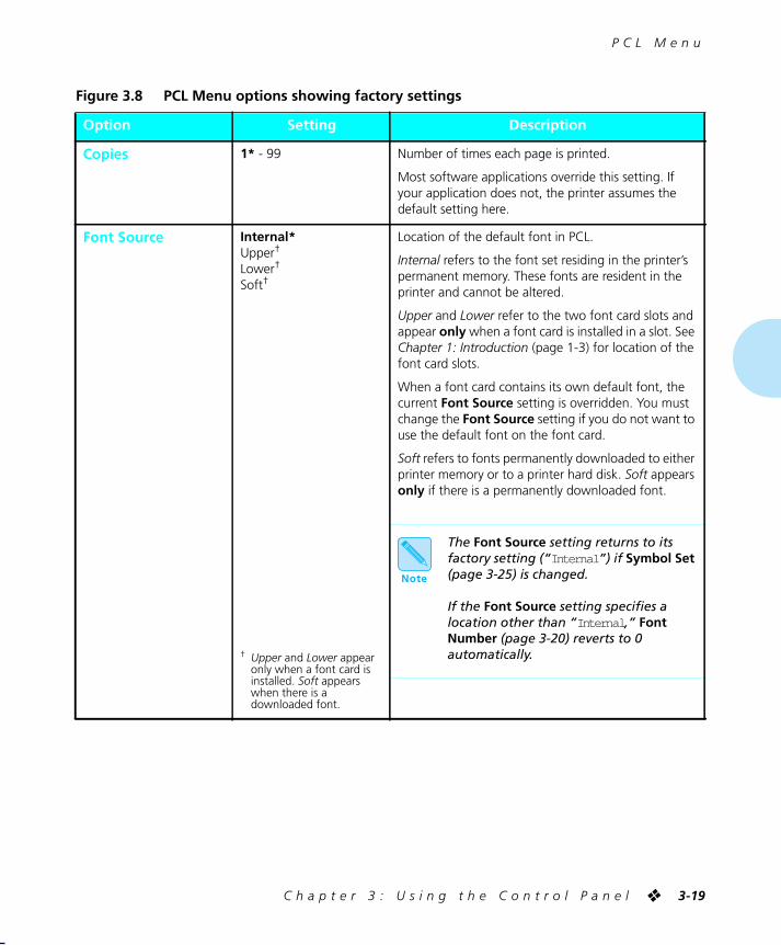
Figure 3.8 PCL Menu options showing factory settings
Option
Setting
Description
Copies
1*
- 99 Number of times each page is printed.
Most software applications override this setting. If your application does not, the printer assumes the default setting here.
Font Source
Internal*
Upper
†
Lower
†
Soft
†
†
Upper
and
Lower
appear only when a font card is installed.
Soft
appears when there is a downloaded font.
Location of the default font in PCL.
Internal
refers to the font set residing in the printer’s permanent memory. These fonts are resident in the printer and cannot be altered.
Upper
and
Lower
refer to the two font card slots and appear
only
when a font card is installed in a slot. See
Chapter 1: Introduction
(page 1-3) for location of the font card slots.
When a font card contains its own default font, the current
Font Source
setting is overridden. You must change the
Font Source
setting if you do not want to use the default font on the font card.
Soft
refers to fonts permanently downloaded to either printer memory or to a printer hard disk.
Soft
appears
only
if there is a permanently downloaded font.
The
Font Source
setting returns to its factory setting (“
Internal
”) if
Symbol Set
(page 3-25) is changed.
If the
Font Source
setting specifies a location other than “
Internal
,”
Font Number
(page 3-20) reverts to 0
automatically.
Note
WUG-CH03 Page 19 Black,Red,Cyan Tuesday, March 21, 1995 4:54 PM

P C L M e n u
3-20
❖
4 5 2 0 / 4 5 2 0 m p U s e r ’ s G u i d e
Font Number
0*
- 999 Default font in PCL.
Only
Font Number
values valid for the
Font Source
location (page 3-19) are displayed. For example, if you have
internal
fonts only, the maximum
Font Number
is 56.
Font Number
values are printed on the
PCL Font List
(page 3-65) in the first column. Print a
PCL Font List
to find the correct number to use with this setting.
The
Font Number
setting returns to its factory setting (0) if the
Symbol Set
(page 3-25) default is changed.
If the
Font Source
setting (page 3-19) specifies a location other than “Internal,”
Font Number
reverts to 0
automatically.
Pitch
.44 - 99.99 by .01(
10.00*
)Number of characters per inch (cpi) for the font represented by
Font Number
(page 3-20).
Appears only when the
Font Number
setting specifies a scalable fixed pitch font, such as Courier.
Up
increments pitch at .01 cpi, from .44 to 99.99 cpi.
Down
decrements at .01 cpi.
Most software applications override this setting. If your application does not, the printer assumes the default setting here.
Figure 3.8 PCL Menu options showing factory settings
(continued)
Option
Setting
Description
Note
WUG-CH03 Page 20 Black,Red,Cyan Tuesday, March 21, 1995 4:54 PM

P C L M e n u
C h a p t e r 3 : U s i n g t h e C o n t r o l P a n e l
❖
3-21
Point Size
4.00 - 999.75 by .25(
12.00*
)Point size (a measurement for type height, 1 point equals 0.351 mm or approximately 1/72 inch) for the font represented by
Font Number
(page 3-20).
Appears only when the
Font Number
setting specifies a scalable proportional spaced font, such as Times New Roman.
Most software applications override this setting. If your application does not, the printer assumes the default setting here.
Default Source
Upper*
ManualManual EnvelopeLowerLarge Capacity
†
Envelope Feeder
†
†
Appears only when the HCF (for Large Capacity) or HCEF (for Envelope Feeder) option is installed.
Default paper source in PCL if none is specified by your software application.
The printer uses
Default Source
when there is no paper source specified in the print job. Some software applications have a paper source selection called “Auto Select” or “Auto Sheet Feed” which usually results in the omission of a paper source selection in a print job.
When the printer uses
Default Source
,
Source Mapping
(page 3-22) is used to determine the actual tray or slot from which the printer pulls paper. See
Chapter 2: Handling Paper
,
“Selecting a Paper Source” (page 2-30)
for more information on the interaction of
Default Source
and
Source Mapping
.
Figure 3.8 PCL Menu options showing factory settings
(continued)
Option
Setting
Description
WUG-CH03 Page 21 Black,Red,Cyan Tuesday, March 21, 1995 4:54 PM

P C L M e n u
3-22
❖
4 5 2 0 / 4 5 2 0 m p U s e r ’ s G u i d e
Source Mapping
Options (Paper Sources):
Upper Manual Manual Envelope Lower Large Capacity Envelope Feeder
UpperMiddleLowerUpper-MiddleUpper-LowerMiddle-LowerUp-Mid-LowManual
†
MBF
‡
HCEF
‡
HCEF-Upper
‡
HCEF-Middle
‡
HCEF-Lower
‡
HCEF-Up-Mid
‡
HCEF-Up-Low
‡
HCEF-Mid-Low
‡
HCEF-Up-Mid-Low
‡
HCF
‡
HCF-Upper
‡
HCF-Middle
‡
HCF-Lower
‡
HCF-Up-Mid
‡
HCF-Up-Low
‡
HCF-Mid-Low
‡
HCF-Up-Mid-Low
‡
†
Appears only when the SBF is installed.
‡
Appears only when the option is installed.
Source Mapping
enables you to control
from your software application
the location from which the printer pulls paper.
Each of the six paper sources that can be requested through your application maps to one of the
Source Mapping
settings.
Lower
is the factory setting for the Lower paper source
. Up-Mid-Low
is the factory setting for Upper and Large Capacity.
Manual
is the factory setting for Manual, Manual Envelope, and Envelope Feeder. See
Figure 2.18 (page 2-35)
for a table of factory settings.
When a paper source (e.g.,
Upper
) is mapped to a sequence of trays (e.g.,
Up-Mid-Low
), the printer may switch between them for two purposes:
1) To increase paper capacity.
When the current tray becomes empty, the printer automatically switches to the next tray in the sequence, provided the paper size is the same. For large print jobs, this gives time to reload paper in a tray without the printing being interrupted.
2) To search for the correct paper size to print a page.
If the paper size specified in your software application does not match what is loaded in the current tray, the printer automatically searches the next tray in the sequence for a paper size that matches.
For more information on taking full advantage of
Source Mapping
and for detailed examples of usage, see
“Selecting a Paper Source” (page 2-30)
.
Figure 3.8 PCL Menu options showing factory settings
(continued)
Option
Setting
Description
WUG-CH03 Page 22 Black,Red,Cyan Tuesday, March 21, 1995 4:54 PM

P C L M e n u
C h a p t e r 3 : U s i n g t h e C o n t r o l P a n e l
❖
3-23
Paper Size
A3 (297x420)Ledger (11x17)B4 (250x352)Legal (8.5x14)Folio (8.5x13)
Letter (8.5x11)*
(USA)
A4 (210x297)*
(Europe)
Exec (7.25x10.5)B5 (176x250)A5 (148.5x210)Com-10DLC5
See
Figure 2.3 (page 2-7)
for more paper dimensions.
Paper size used to print a page if no paper size is specified by your software application.
The Xerox printer driver supports all
Paper Size
settings. However, without the Xerox printer driver installed, not all paper sizes may be supported by your software application.
The
Defaults
setting (page 3-61) in the System Menu determines whether the factory setting for
Paper Size
is “A4 (210x297)” or “Letter (8.5x11)”.
MBF Paper Size
Legal (8.5x14)Folio (8.5x13)
Letter (8.5x11)*
(USA)
A4 (210x297)*
(Europe)
Exec (7.25x10.5)B5 (176x250)A5 (148.5x210)Com-10DLC5
See
Figure 2.3 (page 2-7)
for more paper dimensions.
Applies
only
when the optional Multi-sheet Bypass Feeder (MBF) is installed.
MBF Paper Size
communicates the paper size feeding through the MBF. The MBF does not have a size sensor; therefore, you must explicitly tell the printer what MBF paper size to expect. The printer compares the paper size communicated in the print job to the
MBF Paper Size
setting. If different, the printer displays a message informing you what paper size to feed through the MBF.
The
Defaults
setting (page 3-61) in the System Menu determines whether the factory setting for
MBF Paper Size
is “A4 (210x297)” or “Letter (8.5x11)”.
Orientation
Portrait*
Landscape Page orientation.
Portrait
refers to a vertical page;
Landscape
refers to a horizontal page.
Most software applications override this setting. If your application does not, the printer assumes the default setting here.
Figure 3.8 PCL Menu options showing factory settings
(continued)
Option
Setting
Description
WUG-CH03 Page 23 Black,Red,Cyan Tuesday, March 21, 1995 4:54 PM

P C L M e n u
3-24
❖
4 5 2 0 / 4 5 2 0 m p U s e r ’ s G u i d e
Form Length
005 - 128
64*
(Europe)
60*
(USA)
Number of lines per page used in PCL.
The
Form Length
setting is automatically adjusted when the
Paper Size
(page 3-23) default is changed. For example, if you set
Paper Size
to “A4 (210x297),”
Form Length
is adjusted to 64 automatically. If
Paper Size
is set to “Letter (8.5x11),”
Form Length
is adjusted to 60.
Most software applications override this setting. If your application does not, the printer assumes the default setting here.
The
Defaults
setting (page 3-61) in the System Menu determines whether the
Form Length
factory setting is 64 or 60.
Figure 3.8 PCL Menu options showing factory settings
(continued)
Option
Setting
Description
WUG-CH03 Page 24 Black,Red,Cyan Tuesday, March 21, 1995 4:54 PM

P C L M e n u
C h a p t e r 3 : U s i n g t h e C o n t r o l P a n e l
❖
3-25
Symbol Set
DesktopISO L1ISO L2ISO L5ISO-4 UKISO-6 ASCIIISO-11 SwedishISO-15 ItalianISO-17 SpanishISO-21 GermanISO-60 Norw. V1ISO-69 FrenchLegalMath-8Microsoft Publ.PC-8PC-8 DNPC-8 TkPC-850PC-852Pi FontPS MathPS Text
Roman-8*
Ventura Int’l.Ventura MathVentura USWin 3.0Win L1Win L2Win L5
Collection of characters available for a font, including uppercase and lowercase alphabets, punctuation marks, and special characters such as open and close quotation marks or international characters.
Most software applications override this setting. If your application does not, the printer assumes the default setting here.
When you change
Symbol Set
, the settings for
Font Number
(page 3-20) and
Font Source
(page 3-19) are reset to
their factory settings automatically.
Figure 3.8 PCL Menu options showing factory settings
(continued)
Option
Setting
Description
Note
WUG-CH03 Page 25 Black,Red,Cyan Tuesday, March 21, 1995 4:54 PM

P C L M e n u
3-26
❖
4 5 2 0 / 4 5 2 0 m p U s e r ’ s G u i d e
Page Protection
Off*
A4 (210x297)Legal (8.5x14)Letter (8.5x11)Ledger (11x17)A3 (297x420)
See
Figure 2.3 (page 2-7)
for paper dimensions.
Used to reserve memory for a full page of the selected paper size.
When
Off
, memory is not reserved for an entire page. It then becomes possible for a page to be too complex to compose. The result is a
Page Too Complex
error message and the page may be printed on more than one sheet of paper.
When set to a paper size, each page is composed into reserved memory before the paper starts to move through the printer. The printer may slow down slightly with
Page Protection
; however, you will be assured of printing a complex page on one sheet of paper.
Page Protection
can be overridden by software when the Xerox printer driver is installed.
See
“Printer Settings that Affect Memory” (page 3-69)
for further information.
Jam Recovery
Off*
OnDetermines how the printer recovers from a paper jam.
When
On
, the printer reprints any pages in the printer at the time of the jam, after the jam has been cleared. The printer does this by using a portion of memory to store data.
When
Off
, some pages may be lost after the jam has been cleared. The print job must be resent, specifying those pages that did not print as a result of the paper jam.
See
“Printer Settings that Affect Memory” (page 3-69)
for further information.
Figure 3.8 PCL Menu options showing factory settings
(continued)
Option
Setting
Description
WUG-CH03 Page 26 Black,Red,Cyan Tuesday, March 21, 1995 4:54 PM

P C L M e n u
C h a p t e r 3 : U s i n g t h e C o n t r o l P a n e l
❖
3-27
Resolution
300x300
600x600*
400x400800x800
Dots per inch (dpi).
Some software applications override this setting. If your software application does not, the printer assumes the default setting here.
Resolution
can be overridden by software when the Xerox printer driver is installed.
Higher resolutions use more printer memory. See
“Printer Settings that Affect Memory” (page 3-69)
for further information.
Figure 3.8 PCL Menu options showing factory settings
(continued)
Option
Setting
Description
WUG-CH03 Page 27 Black,Red,Cyan Tuesday, March 21, 1995 4:54 PM

P C L M e n u
3-28
❖
4 5 2 0 / 4 5 2 0 m p U s e r ’ s G u i d e
TrueRes
Off
On*
When
On
, smooths the curves in characters and graphics to reduce coarseness, thereby improving image quality.
TrueRes
can be overridden by software when the Xerox printer driver is installed.
State Saving
Off*
OnReserves memory for saving permanently downloaded fonts and macros, when the printer switches from using the PCL printer language to using the PostScript printer language, or when the printer steps down in
Page Protection
or
Resolution
.
When
Off
, all permanently downloaded fonts and macros are cleared from memory when switching PDLs. They must be downloaded again when the printer switches back to PCL from PostScript.
When
On
, permanently downloaded fonts and macros are stored in printer memory. You eliminate the time to download them again when the printer switches back to PCL.
Temporary fonts and macros are always cleared at the end of every print job.
State Saving
requires 20 MB of memory if the PostScript option is installed. If the PostScript option is not installed,
State Saving
may be selected with 16 MB. This will prevent loss of downloaded PCL fonts and macros if applications change the setting of
Resolution
or
Page Protection
. Enabling
State Saving
can have an effect on printing speed with minimum memory installed. It is recommended that this option not be enabled without 20 MB of printer memory. See
“Printer Settings that Affect Memory” (page 3-69)
for further information.
Figure 3.8 PCL Menu options showing factory settings
(continued)
Option
Setting
Description
Note
WUG-CH03 Page 28 Black,Red,Cyan Tuesday, March 21, 1995 4:54 PM

P o s t S c r i p t M e n u
C h a p t e r 3 : U s i n g t h e C o n t r o l P a n e l
❖
3-29
PostScript Menu
options establish the PostScript configuration for the printer. PostScript may be used by software applications to send information and instructions to the printer.
The 4520mp printer is factory-equipped with PostScript.
PostScript is available as an option for the 4520 printer. See
Appendix D: Ordering Information
.
Windows Users:
The Windows PostScript driver for the 4520 allows the user to either download the PostScript header with every job or download it only once. If the printer is used in a network or other shared environment, where both PCL and PostScript jobs are printed, the header will be deleted when the printer switches from PostScript to PCL. Banner sheets printed from Novell networks cause the printer to switch between PostScript and PCL. If banner sheets are printed, insure that the
Language Sensing
option is ON and the default language is
PCL
. To avoid the loss of the PostScript header, select “Download Each Job” in the PostScript driver. The “Already Downloaded” option may be selected if at least 20 MB of memory is installed in the printer and the
State Saving
option is set to ON in the PostScript printer menu. The user is required to download the header at least once for each power on cycle. If several different PostScript applications are used, the “Download Each Job” option will guarantee that the
correct header is always available.
PostScriptMenu
Note
Note
WUG-CH03 Page 29 Black,Red,Cyan Tuesday, March 21, 1995 4:54 PM

P o s t S c r i p t M e n u
3-30
❖
4 5 2 0 / 4 5 2 0 m p U s e r ’ s G u i d e
Macintosh Users:
The Macintosh driver is installed by opening the driver disk and double clicking the OnPAGE installer icon.
Figure 3.9 (page 3-31)
shows the
PostScript Menu hierarchy
,
which appears only when the PostScript option is installed
.
Note
PostScript MenuHierarchy
WUG-CH03 Page 30 Black,Red,Cyan Tuesday, March 21, 1995 4:54 PM

P o s t S c r i p t M e n u
C h a p t e r 3 : U s i n g t h e C o n t r o l P a n e l
❖
3-31
Figure 3.9 PostScript Menu hierarchy showing factory settings
Copies
Default Tray
Tray Switching
Manual Size
Print Errors
Jam Recovery
Resolution
TrueRes
State Saving
Upper*MiddleLowerManualHCF or HCEF†
LanguagePCL MenuPostScript MenuInterface MenuSystem MenuTest Menu
A3 (297x420)Ledger (11x17)B4 (250x352)Legal (8.5x14)Folio (8.5x13)Letter (8.5x11)* (USA)A4 (210x297)* (Europe)Exec (7.25x10.5)B5 (176x250)A5 (148.5x210)Com-10DLC5
1* - 99
Off*On
Off*On
300x300600x600*400x400800x800
OffOn*
Off*On
Off*Upper-MiddleUpper-LowerMiddle-LowerUp-Mid-LowHCEF-Upper†
HCEF-Middle†
HCEF-Lower†
HCEF-Up-Mid†
HCEF-Up-Low†
HCEF-Mid-Low†
HCEF-Up-Mid-Low†
HCF-Upper†
HCF-Middle†
HCF-Lower†
HCF-Up-Mid†
HCF-Up-Low†
HCF-Mid-Low†
HCF-Up-Mid-Low†
†Appears only when the option is installed.
Menu
Note: The default forTray Switching isUp-Mid-Low or
HCF-Up-Mid-Lowfor firmware
releases < 4.06. Thedefault is Off (as
shown at right) forreleases 4.06 and
higher. To determinethe firmware release
of your printer, print aConfiguration Sheet.
WUG-CH03 Page 31 Black,Red,Cyan Tuesday, March 21, 1995 4:54 PM

P o s t S c r i p t M e n u
3-32
❖
4 5 2 0 / 4 5 2 0 m p U s e r ’ s G u i d e
PostScript Menu
options and their settings are described in
Figure 3.10 (page 3-33)
. Factory settings are
boldfaced
, followed by an asterisk (
*
). See
“Setting a Menu Option” (page 3-10)
for the steps to find and change a setting, or refer to the
Document Services for Printing Guide
to use the RUI to change settings.
Default settings for certain
PostScript Menu
options may be overridden from many software applications. If your software application specifies a value for an option below, the printer
PostScript Menu
setting will be ignored:
• Copies
• Default Tray
• Manual Size
• Tray Switching
The Xerox printer driver allows your software application to specify additional PostScript Menu options:
•
Resolution
•
TrueRes
PostScript MenuOptions
Note
WUG-CH03 Page 32 Black,Red,Cyan Tuesday, March 21, 1995 4:54 PM

P o s t S c r i p t M e n u
C h a p t e r 3 : U s i n g t h e C o n t r o l P a n e l
❖
3-33
Figure 3.10 PostScript Menu options showing factory settings
Option
Setting
Description
Copies
1*
- 99 Number of times each page is printed.
Most software applications override this setting. If your application does not, the printer assumes the default setting here.
Default Tray
Upper*
MiddleLowerManualHCF
†
HCEF
†
†
Appears only when the option is installed.
Paper tray used if none is specified in your software application.
Tray Switching
Note: The default for Tray Switching is
Up-Mid-Low
or
HCF-Up-Mid-Low
for firmware releases < 4.06. The default is
Off
(as shown at right) for releases 4.06 and higher. To determine the firmware release of your printer, print a Configuration Sheet.
Off
Upper-MiddleUpper-LowerMiddle-LowerUp-Mid-LowHCEF-Upper
†
HCEF-Middle
†
HCEF-Lower
†
HCEF-Up-Mid
†
HCEF-Up-Low
†
HCEF-Mid-Low
†
HCEF-Up-Mid-Low
†
HCF-Upper
†
HCF-Middle
†
HCF-Lower
†
HCF-Up-Mid
†
HCF-Up-Low
†
HCF-Mid-Low
†
HCF-Up-Mid-Low†
†
Appears only when the option is installed.
Sequence of trays the printer uses when printing a page of a PostScript print job.
If the tray requested for the page is included in this sequence then the whole sequence is used instead of the requested tray, the first tray used is the first one in the sequence, going from left to right, that satisfies all page requirements. If the requested tray is not included in this sequence then the requested tray alone is used. For example if this setting is “Upper-Lower” and the lower tray is requested then the upper tray will be used first provided that it contains the requested size of paper.
When this sequence is being used and the current tray runs out of paper then the next tray in the sequence that has the same size paper will be used.
Settings that begin with HCEF only appear when a High Capacity Envelope Feeder is installed.
Settings that begin with HCF only appear when a High Capacity Feeder is installed.
The factory default is HCF-Up-Mid-Low when an HCF is installed or Up-Mid-Low when an HCF is not installed.
PostScript drivers other than the Xerox driver may simply enable or disable
Tray Switching
; they can not specify a setting.
WUG-CH03 Page 33 Black,Red,Cyan Tuesday, March 21, 1995 4:54 PM

P o s t S c r i p t M e n u
3-34
❖
4 5 2 0 / 4 5 2 0 m p U s e r ’ s G u i d e
The
System Menu
options set general printer features.
Figure 3.17 highlights the
System Menu hierarchy
.
Figure 3.17 System Menu hierarchy showing factory settings
System Menu
System MenuHierarchy
LanguagePCL MenuPostScript Menu†
Interface MenuSystem MenuTest Menu
Off*On
OffOnce*Continuous
OffOn*
EuropeUSA
Hex Dump
Chime
System Messages
Auto Continue
Defaults
Disk Spooling†
Power Saver
Off*On
Off*On
Menu
† Appears only when the option is installed.
15 min.30 min.60 min.*90 min.
Note: The SystemMessages option (as
shown at right) isavailable for firmware
releases < 4.06 only.
The Power Saveroption (as shown atright) is available for
firmware releases 4.06and higher.
To determine thefirmware release ofyour printer, print a
Configuration Sheet.
WUG-CH03 Page 59 Black,Red,Cyan Tuesday, March 21, 1995 4:54 PM

P o s t S c r i p t M e n u
C h a p t e r 3 : U s i n g t h e C o n t r o l P a n e l
❖
3-35
Resolution
300x300
600x600*
400x400800x800
Dots per inch (dpi).
Some software applications override this setting. If your software application does not, the printer assumes the default setting here.
Resolution
can be overridden by software when the Xerox printer driver is installed.
Higher resolutions require more printer memory. See
“Printer Settings that Affect Memory” (page 3-69)
for further information.
Figure 3.10 PostScript Menu options showing factory settings
(continued)
Option
Setting
Description
WUG-CH03 Page 35 Black,Red,Cyan Tuesday, March 21, 1995 4:54 PM

P o s t S c r i p t M e n u
3-36
❖
4 5 2 0 / 4 5 2 0 m p U s e r ’ s G u i d e
TrueRes
Off
On*
When
On
, smooths the curves in characters and graphics to reduce coarseness, thereby improving image quality.
TrueRes
can be overridden by software when the Xerox printer driver is installed.
Figure 3.10 PostScript Menu options showing factory settings
(continued)
Option
Setting
Description
WUG-CH03 Page 36 Black,Red,Cyan Tuesday, March 21, 1995 4:54 PM

P o s t S c r i p t M e n u
C h a p t e r 3 : U s i n g t h e C o n t r o l P a n e l
❖
3-37
State Saving
Off*
OnReserves memory for saving the contents of virtual memory, when print jobs switch from PostScript to the PCL printer language or when the printer steps down in
Page Protection
or
Resolution
.
When
Off
, if print jobs switch from PostScript to PCL, the contents of virtual memory are cleared.
†
When
On
,
State Saving
saves virtual memory contents, eliminating the time to download again when switching back to PostScript.
State Saving
requires 20 MB of memory if the PostScript option is installed. If the PostScript option is not installed,
State Saving
may be selected with 16 MB. This will prevent loss of downloaded PCL fonts and macros if applications change the setting of
Resolution
or
Page Protection
. Enabling
State Saving
can have an effect on printing speed with minimum memory installed. It is recommended that this option not be enabled without 20 MB of printer memory. See
“Printer Settings that Affect Memory” (page 3-69)
for further information.
The contents of virtual memory will not be saved if there is not enough free
memory.
†
The Windows PostScript driver for the 4520 allows the user to either download the PostScript header with every job or download it only once. If the printer is used in a network or other shared environment, where both PCL and PostScript jobs are printed, the header will be deleted when the printer switches from PostScript to PCL. Banner sheets printed from Novell networks cause the printer to switch between PostScript and PCL. If banner sheets are printed, insure that the
Language Sensing
option is ON and the default language is
PCL
. To avoid the loss of the PostScript header, select “Download Each Job” in the PostScript driver. The “Already Downloaded” option may be selected if at least 20 MB of memory is installed in the printer and the
State Saving
option is set to ON in the PostScript printer menu. The user is required to download the header at least once for each power on cycle. If several different PostScript applications are used, the “Download Each Job” option will guarantee that the correct header is always available
.
Figure 3.10 PostScript Menu options showing factory settings
(continued)
Option
Setting
Description
Note
WUG-CH03 Page 37 Black,Red,Cyan Tuesday, March 21, 1995 4:54 PM

I n t e r f a c e M e n u
3-38
❖
4 5 2 0 / 4 5 2 0 m p U s e r ’ s G u i d e
The
Interface Menu
contains submenus for the
parallel
and
serial
ports on the printer as well as submenus for
network interface
ports
when a network option(s) is installed
.
The
Interface Menu
may include submenus for the following:
•
Parallel Menu
(See page 3-42.)
•
Serial Menu
(See page 3-46.)
•
LocalTalk Menu
(See page 3-51.)
•
Ethernet Menu
(See page 3-52.)
•
Token Ring Menu
(See page 3-55.)
Figure 3.11 (page 3-39)
shows the
Interface Menu hierarchy.
InterfaceMenu
Interface MenuHierarchy
WUG-CH03 Page 38 Black,Red,Cyan Tuesday, March 21, 1995 4:54 PM

I n t e r f a c e M e n u
C h a p t e r 3 : U s i n g t h e C o n t r o l P a n e l
❖
3-39
Figure 3.11 Interface Menu hierarchy showing factory settings
LanguagePCL MenuPostScript Menu†
Interface MenuSystem MenuTest Menu
Port Enable
Port Timeout
System Language
Lang. Sensing
Auto Job End
Bidirectional
Transfer Rate
OffOn*
5- 999 secs (30*)
PCL*PostScript†
OffOn*
OffOn*
Off*On
HighLow*
Parallel Menu
Menu
† Appears only when the PostScript option is installed.
WUG-CH03 Page 39 Black,Red,Cyan Tuesday, March 21, 1995 4:54 PM

I n t e r f a c e M e n u
3-40
❖
4 5 2 0 / 4 5 2 0 m p U s e r ’ s G u i d e
Figure 3.11 Interface Menu hierarchy showing factory settings
(continued)
Serial Menu
Port Enable
Port Timeout
System Language
Lang. Sensing
Auto Job End
Port Type
Baud Rate
Handshake
DTR Polarity
Data Bits
Parity
Stop Bits
OffOn*
PCL*PostScript†
OffOn*
OffOn*
RS232*RS422
38400192009600*480024001200600300
Robust XON*XONHardware
High*Low
78*
None*EvenOdd
21.51*
5 - 999 secs (30*)
WUG-CH03 Page 40 Black,Red,Cyan Tuesday, March 21, 1995 4:54 PM

I n t e r f a c e M e n u
C h a p t e r 3 : U s i n g t h e C o n t r o l P a n e l
❖
3-41
Figure 3.11 Interface Menu hierarchy showing factory settings
(continued)
LocalTalk Menu‡
Ethernet Menu‡
Token Ring Menu‡
Port Timeout 5 - 999 secs (30*)
Port Timeout
System Language
Lang. Sensing
Auto Job End
Frame Type
5 - 999 secs (30*)
PCL*PostScript†
OffOn*
OffOn*
Port Timeout
System Language
Lang. Sensing
Auto Job End
5 - 999 secs (30*)
PCL*PostScript†
OffOn*
OffOn*
802.3*Ethernet II
† Appears only when the PostScript option is installed.‡ Appears only when the option is installed.
Note: The Frame Typeoption (as shown atright) is available for
firmware releases < 4.06only. To determine the
firmware release of yourprinter, print a
Configuration Sheet.
WUG-CH03 Page 41 Black,Red,Cyan Tuesday, March 21, 1995 4:54 PM

I n t e r f a c e M e n u
3-42
❖
4 5 2 0 / 4 5 2 0 m p U s e r ’ s G u i d e
The
Parallel Menu
, a submenu of the
Interface Menu
,
Figure 3.11 (page 3-39)
, contains options for configuring the printer’s bidirectional parallel port.
Figure 3.12 describes each
Parallel Menu
option. Factory settings are
boldfaced
and followed by an asterisk (
*
). See
“Setting a Menu Option” (page 3-10)
for the steps to find and change a setting, or refer to the
Document Services for Printing Guide
to use the RUI to change settings.
Figure 3.12 Parallel Menu options showing factory settings
Option
Setting
Description
Port Enable
Off
On*
Activation of the parallel port.
When
On
, the parallel port is enabled so that the printer can receive print jobs through it.
The parallel port becomes part of a port polling sequence that includes all ports. See
Appendix C: I/O Port Polling
for information.
When
Off
, the port is disabled so no communication occurs through this port with the host. If you are not using the parallel port, you can set
Port Enable
Off
.
Port Timeout
5-999 secs (
30*
) Time interval for determining when to end an incomplete print job and poll the next port in the polling sequence.
Port Timeout
works in conjunction with
Auto Job End
(page 3-44).
See
Appendix C: I/O Port Polling
for more information.
System Language
PCL*
PostScript
†
†
Appears only when the PostScript option is installed.
Page description language (PDL) the printer will use for print jobs coming through the parallel port.
When
Lang. Sensing
(page 3-43) is
On
,
System Language
is used only when the printer cannot detect the PDL used in the incoming print job.
Parallel MenuOptions
WUG-CH03 Page 42 Black,Red,Cyan Tuesday, March 21, 1995 4:54 PM

I n t e r f a c e M e n u
C h a p t e r 3 : U s i n g t h e C o n t r o l P a n e l
❖
3-43
Lang. Sensing
Off
On*
Automatic recognition of the page description language (PDL) used in an incoming print job.
When
On
, if the parallel port receives print jobs of different PDLs—such as a PostScript print job followed by a PCL print job—it can automatically sense which PDL the print job is using. It does this by sampling the incoming data stream, then switching to the perceived language for that job or to the
System Language
setting if it fails to sense the language.
When
On
, if
State Saving
(page 3-28) in the PCL Menu or
State Saving
(page 3-37) in the PostScript Menu is also
On
, the permanently downloaded fonts and macros are saved in memory, eliminating the time to download them again when switching between PDLs occurs.
Figure 3.12 Parallel Menu options showing factory settings
(continued)
Option
Setting
Description
WUG-CH03 Page 43 Black,Red,Cyan Tuesday, March 21, 1995 4:54 PM

I n t e r f a c e M e n u
3-44
❖
4 5 2 0 / 4 5 2 0 m p U s e r ’ s G u i d e
Auto Job End
Off
On*
Automatic ending of a print job that does not finish.
When
On
, after the current print job has paused long enough to exceed the
Port Timeout
(page 3-42) interval and no data has been received on any other port, the print job will be stopped. Any partial page is ejected from the printer and the print job is cleared from memory.
Use
Auto Job End
On
when the printer serves multiple users on a network. This assures that one user’s print job will finish and all pages will exit the printer whether or not another user sends a print job. No partial pages will be left unprinted.
When
Off
, the print job does not end after the timeout interval. Instead, the printer waits to continue until another print job is received on any port. A partial page will remain unprinted until the next print job is received. See
Form Feed
(page 3-5) for information on ejecting partial pages.
Auto Job End
should be
On
if the printer is on a network.
If you are not sharing the printer with other users and if you find that one page is split and printed on multiple pages, set
Auto Job End
Off
or increase the
Port Timeout
interval. It could be the
Port Timeout
is exceeded before the rest of the page can be sent.
Also see
“Printer Settings that Affect Memory” (page 3-69)
for other ways to correct the problem of one page printing on multiple pages.
With the Hard Disk option installed and
Disk Spooling
On
,
Auto Job End
is always
on (regardless of setting).
Figure 3.12 Parallel Menu options showing factory settings
(continued)
Option
Setting
Description
Note
Note
WUG-CH03 Page 44 Black,Red,Cyan Tuesday, March 21, 1995 4:54 PM

I n t e r f a c e M e n u
C h a p t e r 3 : U s i n g t h e C o n t r o l P a n e l
❖
3-45
Bidirectional
Off*
OnActivation of two-way communications between the printer and your computer.
Bidirectional
On
enables the printer to send messages to your computer.
Only set Bidirectional
On
if you have a software application that supports it.
Transfer Rate
High
Low*
Relative speed of the port.
The
High
setting will free up the host more quickly for other processing. If your computer cannot handle the high speed, data may be lost.
Figure 3.12 Parallel Menu options showing factory settings
(continued)
Option
Setting
Description
!Caution
WUG-CH03 Page 45 Black,Red,Cyan Tuesday, March 21, 1995 4:54 PM

I n t e r f a c e M e n u
3-46
❖
4 5 2 0 / 4 5 2 0 m p U s e r ’ s G u i d e
The
Serial Menu
, a submenu of the
Interface Menu
,
Figure 3.11 (page 3-39)
, contains options for configuring the printer’s serial port.
Figure 3.13 describes each
Serial Menu
option. Factory settings are
boldfaced
and followed by an asterisk (
*
). See
“Setting a Menu Option” (page 3-10)
for the steps to find and change a setting, or refer to the
Document Services for Printing Guide
to use the RUI to change settings.
Figure 3.13 Serial Menu options showing factory settings
Option
Setting
Description
Port Enable
Off
On*
Activation of the serial port.
When
On
, the serial port is enabled so that the printer can receive print jobs through it.
The serial port becomes part of a port polling sequence that includes all ports. See
Appendix C: I/O Port Polling
for information.
When
Off
, the port is disabled so no communication occurs through this port with the host. If you are not using the serial port, you can set
Port Enable
Off
.
Port Timeout
5-999 secs (
30*
) Time interval for determining when to end an incomplete print job and poll the next port in the polling sequence.
Port Timeout
works in conjunction with
Auto Job End
(page 3-48).
See
Appendix C: I/O Port Polling
for more information.
System Language
PCL*
PostScript
†
†
Appears only when the PostScript option is installed.
Page description language (PDL) the printer will use for print jobs coming through the serial port.
When
Lang. Sensing
(page 3-47) is
On
,
System Language
is used only when the printer cannot detect the PDL used in the incoming print job.
Serial MenuOptions
WUG-CH03 Page 46 Black,Red,Cyan Tuesday, March 21, 1995 4:54 PM

I n t e r f a c e M e n u
C h a p t e r 3 : U s i n g t h e C o n t r o l P a n e l
❖
3-47
Lang. Sensing
Off
On*
Automatic recognition of the page description language (PDL) used in an incoming print job.
When
On
, if the serial port receives print jobs of different PDLs—such as a PostScript print job followed by a PCL print job—it can automatically sense which PDL the print job is using. It does this by sampling the incoming data stream, then switching to the perceived language for that job or to the
System Language
setting if it fails to sense the language.
When
On
, if
State Saving
(page 3-28) in the PCL Menu or
State Saving
(page 3-37) in the PostScript Menu is also
On
, the permanently downloaded fonts and macros are saved in memory, eliminating the time to download them again when switching between PDLs occurs.
Figure 3.13 Serial Menu options showing factory settings
(continued)
Option
Setting
Description
WUG-CH03 Page 47 Black,Red,Cyan Tuesday, March 21, 1995 4:54 PM

I n t e r f a c e M e n u
3-48
❖
4 5 2 0 / 4 5 2 0 m p U s e r ’ s G u i d e
Auto Job End
Off
On*
Automatic ending of a print job that does not finish.
When
On
, after the current print job has paused long enough to exceed the
Port Timeout
(page 3-46) interval and no data has been received on any other port, the print job will be stopped. Any partial page is ejected from the printer and the print job is cleared from memory.
Use
Auto Job End
On
when the printer serves multiple users on a network. This assures that one user’s print job will finish and all pages will exit the printer whether or not another user sends a print job. No partial pages will be left unprinted.
When
Off
, the print job does not end after the timeout interval. Instead, the printer waits to continue until another print job is received on any port. A partial page will remain unprinted until the next print job is received. See
Form Feed
(page 3-5) for information on ejecting partial pages.
Auto Job End
should be
On
if the printer is on a network.
If you are not sharing the printer with other users and if you find that one page is split and printed on multiple pages, set
Auto Job End
Off
or increase the
Port Timeout
interval. It could be the
Port Timeout
is exceeded before the rest of the page can be sent.
Also see
“Printer Settings that Affect Memory” (page 3-69)
for other ways to correct the problem of one page printing on multiple pages.
With the Hard Disk option installed and
Disk Spooling
On
,
Auto Job End
is always
on (regardless of setting).
Figure 3.13 Serial Menu options showing factory settings
(continued)
Option
Setting
Description
Note
Note
WUG-CH03 Page 48 Black,Red,Cyan Tuesday, March 21, 1995 4:54 PM

I n t e r f a c e M e n u
C h a p t e r 3 : U s i n g t h e C o n t r o l P a n e l
❖
3-49
Port Type
RS232*
RS422Serial interface standard.
Baud Rate
3840019200
9600*
480024001200600300
Speed at which data is transferred.
Baud rate
translates approximately to
bits per second
.
The serial port
Baud Rate
setting must match the host computer baud rate setting.
Your software application may set the baud rate. If not, use the DOS MODE command to modify the baud rate on the host computer. Refer to your DOS
documentation for more information.
Handshake
Robust XON*
XONHardware
Data flow control. (Flow control, also known as handshaking, is the cooperation between the host computer and printer for data transfer. XON signals the host computer to send more data. XOFF is the converse signal that tells the host computer to stop and wait.)
Robust XON
sends the XON signal continuously.
Robust XON
helps ensure that handshaking works with a host computer that fails to receive the XON signal.
XON
sends the signal only once.
Hardware
is used when the host computer cannot operate in XON/XOFF handshaking mode.
Hardware
requires a cable with the DTR (Data Terminal Ready) pin connection enabled
.
Figure 3.13 Serial Menu options showing factory settings
(continued)
Option
Setting
Description
Note
WUG-CH03 Page 49 Black,Red,Cyan Tuesday, March 21, 1995 4:54 PM

I n t e r f a c e M e n u
3-50
❖
4 5 2 0 / 4 5 2 0 m p U s e r ’ s G u i d e
DTR Polarity
High*
LowSerial port’s DTR (Data Terminal Ready) signal sent from the printer to notify the host computer that it is ready to receive data.
High
is standard for most computers; it uses true logic (+5 V).
Low
is typically used on nonstandard equipment; it uses inverted logic (0 V).
Data Bits
7
8*
Number of data bits in a character.
The
Data Bits
setting must match the host computer data bits setting.
Parity
None*
EvenOdd
How the parity bit is used in error checking.
The parity bit may be checked against the received character by means of an
Even
or
Odd
error checking mechanism.
The
Parity
setting must match the host computer parity setting.
Stop Bits
21.5
1*
Number of stop bits in each character. (Stop bits signal the end of a character.)
The
Stop Bits
setting must match the host computer stop bits setting.
Figure 3.13 Serial Menu options showing factory settings
(continued)
Option
Setting
Description
Note
Note
Note
WUG-CH03 Page 50 Black,Red,Cyan Tuesday, March 21, 1995 4:54 PM

I n t e r f a c e M e n u
C h a p t e r 3 : U s i n g t h e C o n t r o l P a n e l
❖
3-51
The
LocalTalk Menu
, a submenu of the
Interface Menu
,
Figure 3.11 (page 3-39)
, contains a single option for configuring the printer’s LocalTalk port, when the LocalTalk option has been installed.
The LocalTalk option supports AppleTalk protocols. For detailed information on the supported protocols, refer to
Networking: LocalTalk
packaged with the LocalTalk option.
Figure 3.14 describes the option. The factory setting is
boldfaced
and followed by an asterisk (
*
). See
“Setting a Menu Option” (page 3-10)
for the steps to find and change the setting.
Figure 3.14 LocalTalk Menu option showing factory setting
Option
Setting
Description
Port Timeout
5-999 secs (
30*
) Time interval for determining when to poll the next port in the polling sequence, after the LocalTalk port has been inactive for this amount of time.
LocalTalk MenuOption
WUG-CH03 Page 51 Black,Red,Cyan Tuesday, March 21, 1995 4:54 PM

I n t e r f a c e M e n u
3-52
❖
4 5 2 0 / 4 5 2 0 m p U s e r ’ s G u i d e
The
Ethernet Menu
, a submenu of the
Interface Menu
,
Figure 3.11 (page 3-39)
, contains options for configuring the printer’s Ethernet port,
when the Ethernet option has been installed
.
The 4520mp printer is factory equipped with the Ethernet option.
Ethernet is available as an option for the 4520 printer. See
Appendix D: Ordering Information
.
The Ethernet option supports the following protocols:
• Novell NetWare, Version 2.x and 3.x
• TCP/IP
• EtherTalk
• DEC LAT
• Microsoft LAN Manager
For detailed information on the supported protocols, refer to
Networking: Ethernet
packaged with the 4520mp printer or with the Ethernet option kit.
Figure 3.15 (page 3-53)
describes each
Ethernet Menu
option. Factory settings are
boldfaced
and followed by an asterisk (
*
). See
“Setting a Menu Option” (page 3-10)
for the steps to find and change a setting, or refer to the
Document Services for Printing Guide
to use the RUI to change settings.
Ethernet MenuOptions
Note
WUG-CH03 Page 52 Black,Red,Cyan Tuesday, March 21, 1995 4:54 PM

I n t e r f a c e M e n u
C h a p t e r 3 : U s i n g t h e C o n t r o l P a n e l
❖
3-53
Figure 3.15 Ethernet Menu options showing factory settings
Option
Setting
Description
Port Timeout
5-999 secs (
30*
) Time interval for determining when to end an incomplete print job and poll the next port in the polling sequence.
Port Timeout
works in conjunction with
Auto Job End
(page 3-54).
See
Appendix C: I/O Port Polling
for more information.
System Language
PCL*
PostScript
†
†
Appears only when the PostScript option is installed.
Page description language (PDL) the printer will use for print jobs coming through the Ethernet port.
When
Lang. Sensing
(page 3-53) is
On
,
System Language
is used only when the printer cannot detect the PDL used in the incoming print job.
Lang. Sensing
Off
On*
Automatic recognition of the page description language (PDL) used in an incoming print job.
When
On
, if the Ethernet port receives print jobs of different PDLs—such as a PostScript print job followed by a PCL print job—it can automatically sense which PDL the print job is using. It does this by sampling the incoming data stream, then switching to the perceived language for that job or to the
System Language
setting if it fails to sense the language.
When
On
, if
State Saving
(page 3-28) in the PCL Menu or
State Saving
(page 3-37) in the PostScript Menu is also
On
, the permanently downloaded fonts and macros are saved in memory, eliminating the time to download them again when switching occurs between PDLs.
WUG-CH03 Page 53 Black,Red,Cyan Tuesday, March 21, 1995 4:54 PM

I n t e r f a c e M e n u
3-54
❖
4 5 2 0 / 4 5 2 0 m p U s e r ’ s G u i d e
Auto Job End
Off
On*
Automatic ending of a print job that does not finish.
When
On
, after the current print job has paused long enough to exceed the
Port Timeout
(page 3-51) interval and no data has been received on any other port, the print job will be stopped. Any partial page is ejected from the printer and the print job is cleared from memory.
Use
Auto Job End
On
when the printer serves multiple users on a network. This assures that one user’s print job will finish and all pages will exit the printer whether or not another user sends a print job. No partial pages will be left unprinted.
When
Off
, the print job does not end after the timeout interval. Instead, the printer waits to continue until another print job is received on any port. A partial page will remain unprinted until the next print job is received. See
Form Feed
(page 3-5) for information on ejecting partial pages.
Auto Job End
should be
On
if the printer is on a network.
If you are not sharing the printer with other users and if you find that one page is split and printed on multiple pages, set
Auto Job End
Off
or increase the
Port Timeout
interval. It could be the
Port Timeout
is exceeded before the rest of the page can be sent.
Also see
“Printer Settings that Affect Memory” (page 3-69)
for other ways to correct the problem of one page printing on multiple pages.
Frame Type
Note: This option is available for firmware releases < 4.06 only. To determine the firmware release of your printer, print a Configuration Sheet.
802.3*
Ethernet IIProtocol standard frame type.
Refer to your network software documentation for the correct frame type.
Figure 3.15 Ethernet Menu options showing factory settings
(continued)
Option
Setting
Description
Note
WUG-CH03 Page 54 Black,Red,Cyan Tuesday, March 21, 1995 4:54 PM

I n t e r f a c e M e n u
C h a p t e r 3 : U s i n g t h e C o n t r o l P a n e l
❖
3-55
The
Token Ring Menu
, a submenu of the
Interface Menu
,
Figure 3.11 (page 3-39)
, contains options for configuring the printer’s Token Ring port,
when the Token Ring option has been installed
.
The Token Ring option supports the following protocols:
• Novell NetWare, Version 2.x and 3.x
• Microsoft LAN Manager
For detailed information on the supported protocols, refer to
Networking: Token Ring
packaged with the Token Ring option kit.
Figure 3.16 (page 3-56)
describes each
Token Ring Menu
option. Factory settings are
boldfaced
and followed by an asterisk (
*
). See
“Setting a Menu Option” (page 3-10)
for the steps to find and change a setting, or refer to the
Document Services for Printing Guide
to use the RUI to change settings.
Token RingMenu Options
WUG-CH03 Page 55 Black,Red,Cyan Tuesday, March 21, 1995 4:54 PM

I n t e r f a c e M e n u
3-56
❖
4 5 2 0 / 4 5 2 0 m p U s e r ’ s G u i d e
Figure 3.16 Token Ring Menu options showing factory settings
Option
Setting
Description
Port Timeout
5-999 secs (
30*
) Time interval for determining when to end an incomplete print job and poll the next port in the polling sequence.
Port Timeout
works in conjunction with
Auto Job End
(page 3-58).
See
Appendix C: I/O Port Polling
for more information on how port polling works.
System Language
PCL*
PostScript
†
†
Appears only when the PostScript option is installed.
Page description language (PDL) the printer will use for print jobs coming through the Token Ring port.
When
Lang. Sensing
(page 3-57) is
On
,
System Language
is used only when the printer cannot detect the PDL used in the incoming print job.
WUG-CH03 Page 56 Black,Red,Cyan Tuesday, March 21, 1995 4:54 PM

I n t e r f a c e M e n u
C h a p t e r 3 : U s i n g t h e C o n t r o l P a n e l
❖
3-57
Lang. Sensing
Off
On*
Automatic recognition of the page description language (PDL) used in an incoming print job.
When
On
, if the Token Ring port receives print jobs of different PDLs—such as a PostScript print job followed by a PCL print job—it can automatically sense which PDL the print job is using. It does this by sampling the incoming data stream, then switching to the perceived language for that job or to the
System Language
setting if it fails to sense the language.
When
On
, if
State Saving
(page 3-28) in the PCL Menu or
State Saving
(page 3-37) in the PostScript Menu is also
On
, the permanently downloaded fonts and macros are saved in memory, eliminating the time to download them again when switching between PDLs occurs.
Figure 3.16 Token Ring Menu options showing factory settings
(continued)
Option
Setting
Description
WUG-CH03 Page 57 Black,Red,Cyan Tuesday, March 21, 1995 4:54 PM

I n t e r f a c e M e n u
3-58
❖
4 5 2 0 / 4 5 2 0 m p U s e r ’ s G u i d e
Auto Job End
Off
On*
Automatic ending of a print job that does not finish.
When
On
, after the current print job has paused long enough to exceed the
Port Timeout
(page 3-56) interval and no data has been received on any other port, the print job will be stopped. Any partial page is ejected from the printer and the print job is cleared from memory.
Use
Auto Job End
On
when the printer serves multiple users on a network. This assures that one user’s print job will finish and all pages will exit the printer whether or not another user sends a print job. No partial pages will be left unprinted.
When
Off
, the print job does not end after the timeout interval. Instead, the printer waits to continue until another print job is received on any port. A partial page will remain unprinted until the next print job is received. See
Form Feed
(page 3-5) for information on ejecting partial pages.
Auto Job End
should be
On
if the printer is on a network.
If you are not sharing the printer with other users and if you find that one page is split and printed on multiple pages, set
Auto Job End
Off
or increase the
Port Timeout
interval. It could be the
Port Timeout
is exceeded before the rest of the page can be sent.
Also see
“Printer Settings that Affect Memory” (page 3-69)
for other ways to correct the problem of one page printing on multiple pages.
Figure 3.16 Token Ring Menu options showing factory settings
(continued)
Option
Setting
Description
Note
WUG-CH03 Page 58 Black,Red,Cyan Tuesday, March 21, 1995 4:54 PM

S y s t e m M e n u
C h a p t e r 3 : U s i n g t h e C o n t r o l P a n e l
❖
3-59
The
System Menu
options set general printer features.
Figure 3.17 highlights the
System Menu hierarchy
.
Figure 3.17 System Menu hierarchy showing factory settings
System Menu
System MenuHierarchy
LanguagePCL MenuPostScript Menu†
Interface MenuSystem MenuTest Menu
Off*On
OffOnce*Continuous
OffOn*
EuropeUSA
Hex Dump
Chime
System Messages
Auto Continue
Defaults
Disk Spooling†
Power Saver
Off*On
Off*On
Menu
† Appears only when the option is installed.
15 min.30 min.60 min.*90 min.
Note: The SystemMessages option (as
shown at right) isavailable for firmware
releases < 4.06 only.
The Power Saveroption (as shown atright) is available for
firmware releases 4.06and higher.
To determine thefirmware release ofyour printer, print a
Configuration Sheet.
WUG-CH03 Page 59 Black,Red,Cyan Tuesday, March 21, 1995 4:54 PM

S y s t e m M e n u
3-60
❖
4 5 2 0 / 4 5 2 0 m p U s e r ’ s G u i d e
In Figure 3.18,
System Menu
options and their settings are described. Factory settings are
boldfaced
, followed by an asterisk (
*
). See
“Setting a Menu Option” (page 3-10)
for the steps to find and change a setting, or refer to the
Document Services for Printing Guide
to use the RUI to change settings.
Figure 3.18 System Menu options showing factory settings
Option
Setting
Description
Hex Dump
Off*
OnPrint output as hexadecimal codes instead of normal print data.
When
Off
, data is printed normally.
When
On
,
Hex Dump
is used for error checking and error analysis.
When
Hex Dump
is
On
, the Control Panel menus are not available.
Chime
Off
Once*
Continuous
Audible chime signal for attention.
When
Once
, the printer sounds one audible chime when needing attention.
When
Continuous
, the printer sounds frequent audible chimes when needing attention.
When
Off
, no chime sound is produced.
System Messages
Note: This option is available for firmware releases < 4.06 only. To determine the firmware release of your printer, print a Configuration Sheet.
Off
On*
Display of system error messages.
When
On
, system error messages are displayed.
When
Off
, no system messages are displayed.
System MenuOptions
Note
WUG-CH03 Page 60 Black,Red,Cyan Tuesday, March 21, 1995 4:54 PM

S y s t e m M e n u
C h a p t e r 3 : U s i n g t h e C o n t r o l P a n e l
❖
3-61
Auto Continue
Off*
OnControl of the resumption of printing after system errors occur.
Certain errors may occur that halt printer operations. Two examples are:
Out of Memory
and
Page Too Complex.
When
Auto Continue
is
Off
, the printer does not automatically resume.
Enter
must
be pressed before normal printer operations can continue.
When
Auto Continue
is
On
, the printer automatically resumes operation after certain system errors if
Enter
is not pressed within ten seconds.
The
On
setting is useful in a networked environment
.
Defaults
EuropeUSA
Control of default paper size settings in various menus.
There is no standard factory-set default for this option; the default varies by world region.
When
Europe
, all paper size-related options are set to A4 (210x297) and
Form Length
is set to 64.
When
USA
, all paper size-related options are set to Letter (8.5x11) and
Form Length
is set to 60.
The
Config. Sheet
(page 3-64) is printed at
Defaults
size, regardless of actual paper size.
Perform a
Reset Menus
(page 3-68) after changing
Defaults
.
Figure 3.18 System Menu options showing factory settings
(continued)
Option
Setting
Description
Note
WUG-CH03 Page 61 Black,Red,Cyan Tuesday, March 21, 1995 4:54 PM

S y s t e m M e n u
3-62
❖
4 5 2 0 / 4 5 2 0 m p U s e r ’ s G u i d e
Disk Spooling
†
†
Appears only when the hard disk option is installed.
Off*
OnUse of hard disk (if installed) for spooling of print jobs.
When
On
, data received and waiting to be processed from the parallel or serial ports is spooled onto the hard disk and later retrieved for processing.
When
Off
, data received and waiting to be processed is kept in printer memory. Set
Disk Spooling
to
Off
to save time if spooling is already done outside the printer.
Power Saver
Note: This option is only available for firmware releases 4.06 and higher. To determine the firmware release of your printer, print a Configuration Sheet.
15 min.30 min.
60 min.*
90 min.
The Xerox 4520/4520mp printers conform to EPA Energy Star guidelines. The printer will enter a low power state after 60 minutes of inactivity. This timeout is adjustable to 15, 30, 60 or 90 minutes via this option.
When in the low power state, the printer displays
Power Saver On
on the Control Panel. When a print job is received while in the power saver mode, the printer may require up to 30 seconds of warm up time before the first sheet is fed from the input tray.
Figure 3.18 System Menu options showing factory settings
(continued)
Option
Setting
Description
WUG-CH03 Page 62 Black,Red,Cyan Tuesday, March 21, 1995 4:54 PM

T e s t M e n u
C h a p t e r 3 : U s i n g t h e C o n t r o l P a n e l
❖
3-63
Test Menu
options are functions that provide output to help you maintain high quality printing.
Options in the
Test Menu
are
functions
to be performed by the printer rather than settings. There are no submenus.
Figure 3.19 shows the
Test Menu
hierarchy.
Figure 3.19 Test Menu hierarchy
Test Menu
Note
Test MenuHierarchy
LanguagePCL MenuPostScript Menu†
Interface MenuSystem MenuTest Menu Config. Sheet
Demo PagePCL Font ListPS Font List†
Test PrintMemory Check
Menu
† Appears only when the PostScript option is installed.
Note: The Demo Pageoption (as shown at
right) is only availablefor firmware releases
4.06 and higher. Todetermine the
firmware release ofyour printer, print a
Configuration Sheet.
WUG-CH03 Page 63 Black,Red,Cyan Tuesday, March 21, 1995 4:54 PM

T e s t M e n u
3-64
❖
4 5 2 0 / 4 5 2 0 m p U s e r ’ s G u i d e
Figure 3.20 describes each
Test Menu
function. See
“Setting a Menu Option” (page 3-10)
for the steps in performing a
Test Menu
function.
Figure 3.20 Test Menu functions
Function
Description
Config. Sheet
Configuration Sheet to show the printer’s current information and menu settings.
The Configuration Sheet contains a variety of information such as:
• Number of sheets printed to date.
• Total printer memory (RAM) available.
• Firmware versions for the printer controller and print engine.
• Firmware versions for Ethernet, LocalTalk, and Token Ring, when installed.
• PostScript revision level, when installed.
• Current menu settings.
• Hard disk statistics, when installed.
• Information on all installed options including the MBF, HCF, and HCEF.
The Configuration Sheet is printed from the
Default Source
(page 3-21) at the current
Resolution
(page 3-27) setting, both specified in the PCL Menu, using A4 (210x297) paper if the System Menu setting for
Defaults
(page 3-61) is
Europe
, or using Letter (8.5x11) paper if
Defaults
is
USA
.
Config. Sheet
will cause a printer reset.
Demo Page
Note: This option is only available for firmware releases 4.06 and higher. To determine the firmware release of your printer, print a Configuration Sheet.
Demo Page listing Connectivity, Paper Handling, Print Quality and Page Description Languages of the printer.
The Demo Page is printed from the
Default Source
(page 3-21), specified in the PCL Menu, at 600 dpi using A4 (210x297) paper if the System Menu setting for
Defaults
(page 3-61) is
Europe
, or using Letter (8.5x11) paper if
Defaults
is
USA
.
Demo
Page
will cause a printer reset.
Test MenuFunctions
WUG-CH03 Page 64 Black,Red,Cyan Tuesday, March 21, 1995 4:54 PM

T e s t M e n u
C h a p t e r 3 : U s i n g t h e C o n t r o l P a n e l
❖
3-65
PCL Font List
Complete list of all PCL fonts currently available in the printer.
PCL fonts include those that are internal, on font card(s), and permanently downloaded soft fonts. See
Font Source
(page 3-19) for font storage locations.
The
PCL Font List
prints font number, typeface name, whether the font is fixed pitch or proportionally spaced, point size or scalable indication, orientation, other font characteristics, and a font sample.
Printing a
PCL Font List
will cause a printer reset, ejecting any partial pages and clearing any incomplete jobs, temporary fonts, and macros from memory.
The
Font Number
(page 3-20) may change based on what fonts you have loaded and what
Symbol Set
(page 3-25) you are using.
PS Font List
Complete list of the 35 PostScript language typefaces.
With PostScript installed, the
PS Font List
shows all resident PostScript fonts available in the printer, as well as a sample of each.
Figure 3.20 Test Menu functions
(continued)
Function
Description
Note
WUG-CH03 Page 65 Black,Red,Cyan Tuesday, March 21, 1995 4:54 PM

T e s t M e n u
3-66
❖
4 5 2 0 / 4 5 2 0 m p U s e r ’ s G u i d e
Test Print
“Test pattern” for analysis of print quality over the entire page; intended for use by service technician.
The number of Test Prints produced is determined by
Copies
(page 3-19) and printed from the
Default
Source
(page 3-21), both specified in the PCL Menu. If the System menu setting
Defaults
(page 3-61) is
USA
, Letter (8.5x11) paper is used; otherwise, A4 paper is used.
Test Print
will cause a printer reset, clearing any incomplete jobs.
Memory Check
Complete check of printer memory (resident and any SIMMs installed) and a reporting of the results on the Control Panel display.
Memory Check
is more extensive than the check performed when the printer is powered on. When you invoke
Memory Check
, you will see:
Memory CheckPlease Wait....
Before
Memory Check
, any partial pages are ejected and any incomplete print jobs, permanently downloaded fonts, and macros are cleared from memory. After
Memory Check
is finished, it reboots the printer to its power-on state.
If a problem occurs, the Control Panel will display a numeric diagnostic code. See
Chapter 7: Troubleshooting,
“Displayed Control Panel Messages” (page 7-5),
to locate the diagnostic message associated with the numeric code.
Figure 3.20 Test Menu functions
(continued)
Function
Description
WUG-CH03 Page 66 Black,Red,Cyan Tuesday, March 21, 1995 4:54 PM

R e s e t M e n u
C h a p t e r 3 : U s i n g t h e C o n t r o l P a n e l
❖
3-67
The
Reset Menu
offers several functions to reset various printer functions.
Options in the
Reset Menu
are
functions
to be performed by the printer rather than settings. There are no submenus.
Figure 3.21 shows the
Reset Menu hierarchy
.
Figure 3.21 Reset Menu hierarchy
Figure 3.22 (page 3-68)
describes each
Reset Menu
function. See
“Setting a Menu Option” (page 3-10)
for the steps in performing a
Reset Menu
function.
For all types of reset, the printer clears any temporarily downloaded fonts and print macros from memory, as well as ejects any partially printed pages.
Reset Menu
Note
Reset MenuHierarchy
Reset PrinterReset MenusReset AllCancel PS Job†
Reset
† Appears only when the PostScript option is installed.
Reset MenuFunctions
Note
WUG-CH03 Page 67 Black,Red,Cyan Tuesday, March 21, 1995 4:54 PM

R e s e t M e n u
3-68
❖
4 5 2 0 / 4 5 2 0 m p U s e r ’ s G u i d e
Figure 3.22 Reset Menu functions
Functions
Description
Reset Printer
Reset of the printer’s PCL and PostScript printer languages to their power-on state.
Reset Printer
is useful when you have printing problems. First, cancel the print job from the host. Second, invoke
Reset Printer
.
Reset Printer
cancels any print jobs being processed and clears all temporary fonts and macros.
Reset Printer
does not change the menu settings of any network option. However, any current print jobs being processed by a
network option will be discarded.
Reset Menus
Reset of menus to their factory settings.
Reset Menus
does not affect the
Language
setting (page 3-14) or the System Menu
Defaults
setting (page 3-61).
The printer remains offline, so you can work with other menus.
To insure proper operation of this feature, cycle the printer (turn the printer off/on) before invoking
Reset Menus
.
Reset All
All reset functions are performed:
• Reset Printer• Reset Menus
To insure proper operation of this feature, cycle the printer (turn the printer off/on) before invoking
Reset All
.
Cancel PS Job
Cancellation of the current PostScript job.
This function appears only if the PostScript option is installed.
The PostScript job is flushed from memory—the entire print job is discarded.
Cancel PS Job
is useful when a fault in your software application causes a PostScript error. For example, a PostScript programming error could cause an infinite loop which
Cancel PS Job
would exit.
Note
Note
Note
WUG-CH03 Page 68 Black,Red,Cyan Tuesday, March 21, 1995 4:54 PM

P r i n t e r S e t t i n g s t h a t A f f e c t M e m o r y
C h a p t e r 3 : U s i n g t h e C o n t r o l P a n e l
❖
3-69
Certain
PCL Menu
and
PostScript Menu
options affect the printer’s performance and memory usage, as described in
“PCL Menu” (page 3-15)
and
“PostScript Menu” (page 3-29)
.
Figure 3.23 provides more detailed information on these options.
Figure 3.23 PCL and PostScript Menu options that affect performance and memory usage
Option
Description
Page Protection
PCL Menu
(page 3-26)
When a page is particularly complex with graphics or dense text, the printer may not be able to process it rapidly enough to keep up with normal printing operations. Data may be lost or one page may be split on multiple pages.
Page protection
is a technique that reserves memory to ensure the entire page can be created and printed before the actual printing process. The tradeoff in performance is matched by the certainty that an entire complex page may be printed.
Page Protection
is related to
Resolution
(page 3-27 for PCL, page 3-35 for PostScript, and page 3-70) since the amount of memory needed for a page depends on its resolution. The higher the resolution, the more memory needed. See
Figure 3.24 (page 3-72)
for memory requirements.
Your software application may change the
Page Protection
level (e.g., from
Legal
to
Letter
). When that occurs, the printer’s memory is reconfigured. Downloaded fonts and macros may be cleared from memory unless
State Saving
(page 3-28 for PCL, page 3-37 for PostScript, and page 3-71) is set.
If any request for memory cannot be satisfied, you will be notified on the Control Panel.
If you frequently see the following error message
Page Too Complex
you may want to set
Page Protection
to be able to print the entire page. Otherwise, if you do not see frequent warning messages, set
Page Protection
Off
.
PrinterSettings that
AffectMemory
WUG-CH03 Page 69 Black,Red,Cyan Tuesday, March 21, 1995 4:54 PM

P r i n t e r S e t t i n g s t h a t A f f e c t M e m o r y
3-70
❖
4 5 2 0 / 4 5 2 0 m p U s e r ’ s G u i d e
Jam Recovery
PCL Menu
(page 3-26)
PostScript Menu
(page 3-34)
A paper jam may cause a page image being printed to become lost. When
Jam Recovery
is
On
, the printer will automatically reprint the image of the jammed page, after the jam has been cleared.
Because the printer holds a page image in memory longer with
Jam Recovery
, if a low memory condition occurs there can be a slight performance impact and the printer may require more memory. If sufficient memory exists,
Jam Recovery
has no impact.
Resolution
PCL Menu
(page 3-27)
PostScript Menu
(page 3-35)
The printer prints at 800, 600, 400, or 300 dpi. The factory-set default is 600 dpi.
Your software application may be able to set
Resolution
and override the setting here. Whether a new
Resolution
is set by your application or on the Control Panel, the new
Resolution
becomes effective with the next print job or with a printer reset. Unless
State Saving
(page 3-28 for PCL, page 3-37 for PostScript, and page 3-71) is
On
, downloaded fonts and macros may be cleared from memory.
The higher the resolution, the more memory required. See
Figure 3.24 (page 3-72)
for memory requirements.
Figure 3.23 PCL and PostScript Menu options that affect performance and memory usage
Option
Description
WUG-CH03 Page 70 Black,Red,Cyan Tuesday, March 21, 1995 4:54 PM

P r i n t e r S e t t i n g s t h a t A f f e c t M e m o r y
C h a p t e r 3 : U s i n g t h e C o n t r o l P a n e l
❖
3-71
State Saving
PCL Menu
(page 3-28)
PostScript Menu
(page 3-37)
When
State Saving
is
Off
, fonts and printer macros downloaded from your software application are cleared from memory when:
• The printer switches from one page description language (PDL) to another (such as from PostScript to PCL).
• A memory reconfiguration takes place (such as for a new
Page Protection
or
Resolution
setting).
When
State Saving
is
On
, the printer reserves memory to retain the downloaded fonts and macros. Thus, the fonts and macros do not have to be downloaded to memory again when switching PDLs or reconfiguring memory.
You may set
State Saving
separately for the PCL and the PostScript environments.
The Windows PostScript driver for the 4520 allows the user to either download the PostScript header with every job or download it only once. If the printer is used in a network or other shared environment, where both PCL and PostScript jobs are printed, the header will be deleted when the printer switches from PostScript to PCL. Banner sheets printed from Novell networks cause the printer to switch between PostScript and PCL. If banner sheets are printed, insure that the
Language Sensing
option is ON and the default language is
PCL
. To avoid the loss of the PostScript header, select “Download Each Job” in the PostScript driver. The “Already Downloaded” option may be selected if at least 20 MB of memory is installed in the printer and the
State Saving
option is set to ON in the PostScript printer menu. The user is required to download the header at least once for each power on cycle. If several different PostScript applications are used, the “Download Each Job” option will guarantee that the correct header is always available. See
Figure 3.24 (page 3-72)
for memory requirements.
Figure 3.23 PCL and PostScript Menu options that affect performance and memory usage
Option
Description
WUG-CH03 Page 71 Black,Red,Cyan Tuesday, March 21, 1995 4:54 PM

P r i n t e r S e t t i n g s t h a t A f f e c t M e m o r y
3-72
❖
4 5 2 0 / 4 5 2 0 m p U s e r ’ s G u i d e
The memory requirements shown in Figure 3.24 provide for optimal memory usage and printer performance.
If you encounter memory warning messages, try different combinations of
Resolution
and
Page Protection
before purchasing additional memory.
If both the PostScript and hard disk options are installed in the printer, the memory requirements for
PCL
with
Page Protection
set are: 800 dpi Ledger/A3 require 20 MB; all
other sizes require 12 MB.
Figure 3.24 Minimum memory requirements
Setting
300 dpi
400 dpi
600 dpi
800 dpi
PCLwith
Page Protection
Off
All paper sizes:
4 MB
All paper sizes:
4 MB
All paper sizes:
4 MB
Not recommended
PCLwith
Page Protection
set
All paper sizes:
4 MB
All paper sizes:
4 MB
A3/Ledger:
12 MB
All others:
8 MB
A3/Ledger:
16 MB
Legal:
12 MB
All others:
8 MB
PostScript(and PCL)with
State Saving
Off
All paper sizes:
8 MB
All paper sizes:
8 MB
A3/Ledger:
12 MB
All others:
8 MB
A3/Ledger:
20 MB
All others:
12 MB
PCL with
State Saving
On
16 MB 16 MB 16 MB 16 MB
PostScript with
State Saving
On
20 MB 20 MB 20 MB 20 MB
Minimum MemoryRequirements
Note
Note
WUG-CH03 Page 72 Black,Red,Cyan Tuesday, March 21, 1995 4:54 PM
Chapter 4
C h a p t e r 4 : U s i n g F o n t s
❖
4-1
Using Fonts
Chapter 4
Overview
...............................................................................
4-2
Bitmapped and Scalable Fonts 4-2
Where Fonts Reside 4-3
Fonts Resident on the Printer
..............................................
4-4
TrueType Fonts 4-5
Intellifont Fonts 4-6
PCL Bitmap Font 4-7
Adding Fonts
.........................................................................
4-8
PostScript 4-8
Font Cards 4-9
Fonts within Software Applications 4-10
Selecting a Font
..................................................................
4-11
Downloading Fonts
............................................................
4-12
Temporary and Permanent Fonts 4-13
WUG-CH04 Page 1 Black,Cyan Sunday, January 22, 1995 8:27 PM

O v e r v i e w
4-2
❖
4 5 2 0 / 4 5 2 0 m p U s e r ’ s G u i d e
A
font
is a collection of characters of one typeface, one weight, and one posture. An example is Courier New Italic. A font generally contains uppercase and lowercase alphabets, numbers, and special characters such as punctuation marks.
A
font family
is composed of one typeface in all its available weights and postures. Courier New, for example, has medium, italic, bold, and bold italic.
Fonts are normally categorized according to the manner in which they are generated:
•
Bitmapped
font
A bitmapped font contains digitized images of each character in the font. Each symbol (that is, character, number, or punctuation mark) is a
complete
image
in digitized form.
Each symbol is stored as a bitmap (or raster) that represents the black or white parts of the symbol. The bitmaps are copied onto the paper when printing takes place.
•
Scalable
font
A scalable font contains characters described by mathematical formulae that produce
character outlines
. A mathematical formula describes a line between two points which constitutes one line of the character’s outline. The images printed on paper are digitized as the page is being printed. During digitization, the image may be scaled, sloped, or rotated.
There exists a variety of mathematical models used to construct scalable fonts, but the two most popular are Bézier and B-spline.
Scalable fonts are also known as
contour
or
outline
fonts.
Overview
Bitmapped andScalable Fonts
WUG-CH04 Page 2 Black,Cyan Sunday, January 22, 1995 8:27 PM

O v e r v i e w
C h a p t e r 4 : U s i n g F o n t s
❖
4-3
At one time, computers used bitmapped fonts only. One set of bitmapped fonts was needed to display characters on a terminal screen, and another set was needed for printing. These were called
screen fonts
and
printer fonts
, respectively.
Today, software applications use many scalable fonts because they can be used for both screen and printer.
Screen fonts
are always stored on the host computer, not the printer.
Printer fonts
may reside in three places:
•
Printer ROM
holds
resident
fonts, installed at the factory on memory chips on the printer controller board. See
“Fonts Resident on the Printer” (page 4-4)
for a complete list.
• A
font
card
inserted into the printer holds additional PCL fonts. The 4520/4520mp printers provide two slots for font cards. See
Chapter 1: Introduction
(page 1-3) for font card location.
•
Software applications
contain additional fonts that may be
downloaded
to printer memory or the hard disk, in some cases, for the entire time the printer is turned on. See
“Downloading Fonts” (page 4-12)
for more information.
Where FontsReside
WUG-CH04 Page 3 Black,Cyan Sunday, January 22, 1995 8:27 PM

F o n t s R e s i d e n t o n t h e P r i n t e r
4-4
❖
4 5 2 0 / 4 5 2 0 m p U s e r ’ s G u i d e
The 4520/4520mp printers are equipped with resident fonts installed at the factory on memory chips on the printer controller board.
Resident fonts are used by software applications that communicate with the printer in
PCL (Printer Command Language)
. See
Appendix B: Printer Commands (Escape Sequences)
for more information on all PCL commands.
The 4520mp printer is factory-equipped with the PostScript option that makes available 35 PostScript fonts. To review the PostScript fonts, print a
PS Font List
(page 3-65). Also, refer to
your PostScript reference documentation.
Resident fonts available to PCL include the following:
• 10 TrueType fonts. See
“TrueType Fonts” (page 4-5)
.
• 35 Intellifont fonts. See
“Intellifont Fonts” (page 4-6)
.
• 1 PCL Bitmap font. See
“PCL Bitmap Font” (page 4-7)
.
FontsResident onthe Printer
Note
WUG-CH04 Page 4 Black,Cyan Sunday, January 22, 1995 8:27 PM
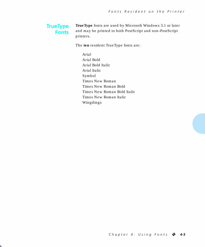
F o n t s R e s i d e n t o n t h e P r i n t e r
C h a p t e r 4 : U s i n g F o n t s
❖
4-5
TrueType
fonts are used by Microsoft Windows 3.1 or later and may be printed to both PostScript and non-PostScript printers.
The
ten
resident TrueType fonts are:
ArialArial BoldArial Bold ItalicArial ItalicSymbolTimes New RomanTimes New Roman BoldTimes New Roman Bold ItalicTimes New Roman ItalicWingdings
TrueTypeFonts
WUG-CH04 Page 5 Black,Cyan Sunday, January 22, 1995 8:27 PM

F o n t s R e s i d e n t o n t h e P r i n t e r
4-6
❖
4 5 2 0 / 4 5 2 0 m p U s e r ’ s G u i d e
Intellifont
is a scalable font format. The printers are fully compatible with this font format and provide the 35 resident Intellifont fonts:
Antique Olive MediumAntique Olive ItalicAntique Olive BoldAlbertus MediumAlbertus Extra BoldCG Omega MediumCG Omega ItalicCG Omega BoldCG Omega Bold ItalicCG Times MediumCG Times ItalicCG Times BoldCG Times Bold ItalicClarendon Cond. BoldCoronet Medium ItalicCourier MediumCourier ItalicCourier BoldCourier Bold Italic
Garamond AntiquaGaramond KursivGaramond HalbfettGaramond Kursiv HalbfettLetter Gothic MediumLetter Gothic ItalicLetter Gothic BoldMarigold MediumUnivers MediumUnivers ItalicUnivers BoldUnivers Bold ItalicUnivers Cond. MediumUnivers Cond. ItalicUnivers Cond. BoldUnivers Cond. Bold Italic
IntellifontFonts
WUG-CH04 Page 6 Black,Cyan Sunday, January 22, 1995 8:27 PM

F o n t s R e s i d e n t o n t h e P r i n t e r
C h a p t e r 4 : U s i n g F o n t s
❖
4-7
The printers have one resident bitmap font called
Line Printer
. It comes in only one typeface, weight, and posture.
The Line Printer font may be used to provide:
• Line printer emulation for a print job.
• Backward compatibility for those applications that make use of the line printer font.
To review the PCL fonts in your printer, print a
PCL Font List
(page 3-65).
PCL BitmapFont
Note
WUG-CH04 Page 7 Black,Cyan Sunday, January 22, 1995 8:27 PM
A d d i n g F o n t s
4-8
❖
4 5 2 0 / 4 5 2 0 m p U s e r ’ s G u i d e
Utilizing fonts in addition to resident fonts can add new dimensions to your work. Additional fonts are available through the:
• PostScript option. See
“PostScript” (page 4-8)
.
• Font cards for PCL fonts. See
“Font Cards” (page 4-9)
.
• Software applications. See
“Fonts within Software Applications” (page 4-10)
.
Thirty-five
PostScript
fonts (Adobe Type 1) are available to your printer, either factory-installed on the 4520mp printer, or user-installable on the 4520 printer as an option. See
Appendix D: Ordering Information
for more information on the PostScript option.
Many additional PostScript fonts are available through Adobe Systems, Inc. and may be used when the PostScript option is installed on your printer.
If you have a 4520mp printer, see
“PostScript Menu” (page 3-29)
for PostScript printer settings.
PostScript fonts are used by the PostScript Level 2 printer language. If you plan to program in the PostScript Level 2 printer language, refer to Adobe Systems, Inc. PostScript language reference documentation.
The
Lang. Sensing
settings in the Parallel (page 3-42), Serial (page 3-46), Ethernet (page 3-52), and Token Ring (page 3-55) Menus enable automatic switching between the PostScript and PCL printer languages.
PostScript and PCL fonts are not
interchangeable
.
Adding Fonts
PostScript
Note
WUG-CH04 Page 8 Black,Cyan Sunday, January 22, 1995 8:27 PM

A d d i n g F o n t s
C h a p t e r 4 : U s i n g F o n t s
❖
4-9
The 4520/4520mp printers are equipped with two font card slots. See
Chapter 1: Introduction
(page 1-3) for the physical location of the slots. See
Chapter 5: Adding Printer Options
for font card installation.
Font cards for the 4520/4520mp contain PCL fonts only
. In addition, font cards may contain one or more scalable fonts or bitmapped fonts. However, bitmapped and scalable fonts are not mixed on the same card.
A font card may contain its own
default
font. In this case, its default font becomes the printer’s default font. To change the default font, see
Chapter 3: Using the Control Panel
,
Font Source
(page 3-19).
To avoid problems when inserting or removing a font card, take the printer offline by pressing Online
PCL font cards may be purchased from Xerox / Rank Xerox. See
Appendix D: Ordering Information
.
Font Cards
!Caution
WUG-CH04 Page 9 Black,Cyan Sunday, January 22, 1995 8:27 PM

A d d i n g F o n t s
4-10
❖
4 5 2 0 / 4 5 2 0 m p U s e r ’ s G u i d e
Certain software applications offer additional fonts to those supplied with your printer. These fonts are stored on the host and then
downloaded
into printer memory by the software application when printing.
Unless specified as permanently downloaded fonts (see page 4-12), software application fonts are downloaded to printer memory before being used for a specific print job and are removed from printer memory after completion of that print job.
Installation of the Xerox printer driver provides the printer with the capability of recognizing which fonts are resident and which are not.
Selecting resident fonts saves memory
and time
.
Fonts withinSoftware
Applications
Note
WUG-CH04 Page 10 Black,Cyan Sunday, January 22, 1995 8:27 PM

S e l e c t i n g a F o n t
C h a p t e r 4 : U s i n g F o n t s
❖
4-11
How is a font selected for printing?
The general answer is that you select a font
within the application you are running
. For example, if you are using a word processing application, you will select a font
from the font list
within the application.
If desired, you may select a font (PCL fonts only) from the Control Panel or Remote User Interface (RUI). For an explanation of how to do this, see
Chapter 3: Using the Control Panel
,
Font Number
(page 3-20), or refer to the
Documentation Services for Printing Guide
for the RUI.
A font selected from the Control Panel or RUI becomes the
default
font for the printer unless overridden by the selection of a different font from your software application.
Selectinga Font
WUG-CH04 Page 11 Black,Cyan Sunday, January 22, 1995 8:27 PM

D o w n l o a d i n g F o n t s
4-12
❖
4 5 2 0 / 4 5 2 0 m p U s e r ’ s G u i d e
Whether you do or do not use additional fonts, it is helpful to know a few facts about how the printer uses fonts either resident in the printer or
downloaded
(transferred) from the host.
Each time you specify a font in a document to be printed, the font is downloaded to printer,
unless the font is already
:
• Resident in the printer’s ROM (read-only memory)
—PCL only
.
• Specified in the printer driver as permanently downloaded to the printer’s internal memory
—PCL only
.
• Installed on the PostScript card
—PostScript only
.
• Installed on a font card
—PCL only
.
• Downloaded to the hard disk.
Consult your software application’s user documentation for a discussion of fonts
associated with that application
.
DownloadingFonts
WUG-CH04 Page 12 Black,Cyan Sunday, January 22, 1995 8:27 PM

D o w n l o a d i n g F o n t s
C h a p t e r 4 : U s i n g F o n t s
❖
4-13
Temporary fonts
are PCL fonts downloaded for a particular print job. As soon as the print job is finished, the fonts are cleared from memory.
They must be downloaded for each print job
that uses them
. Downloading may have an impact on performance, depending on the number of fonts being downloaded. As a result, the print job using downloaded fonts may take longer than one using resident fonts.
As an example, when you print a mostly-text document in a resident font, printing time is optimal.
If you print that same document using a downloaded font, the time to print the first page is substantially longer than it was for your resident-font document. The remaining pages also take longer to print than those of the resident-font document.
For optimal performance, use
resident
fonts whenever applicable since they do not require downloading time.
Permanently downloaded fonts
are PCL fonts downloaded in the same way as temporary fonts, but they
remain downloaded
for all print jobs until the printer is powered off. They are
permanent
only as long as the printer is on.
Similar to resident fonts or those on font cards, permanently downloaded fonts reduce the processing time for a print job that uses them. The distinction is that permanently downloaded fonts occupy printer memory that might be used otherwise.
Temporary andPermanent Fonts
Note
WUG-CH04 Page 13 Black,Cyan Sunday, January 22, 1995 8:27 PM

D o w n l o a d i n g F o n t s
4-14
❖
4 5 2 0 / 4 5 2 0 m p U s e r ’ s G u i d e
How do you know if a font is permanently downloaded?
• Specify a font to be permanently downloaded when it is installed or setup within a software application.
• Print a
PCL Font List
(page 3-65) to see all resident fonts, all fonts installed on any font card, and
all permanently downloaded fonts
.
In general, it is not recommended that you permanently download fonts. Even if unused, permanent fonts occupy printer memory that cannot be used for other purposes.
In a networked environment, carefully coordinate the use of permanently downloaded fonts. Avoid allowing multiple users to specify permanently downloaded fonts since printer memory may be consumed rapidly and may cause printer faults.
Additional memory (SIMMs) will enable the printer to hold more downloaded fonts. See
Chapter 1: Introduction,
“Memory Considerations” (page 1-6) and
Chapter 5: Adding
Printer Options
for more information about printer memory.
Note
WUG-CH04 Page 14 Black,Cyan Sunday, January 22, 1995 8:27 PM
Chapter 5
C h a p t e r 5 : A d d i n g P r i n t e r O p t i o n s
❖
5-1
Adding Printer Options
Chapter 5
Overview
...............................................................................
5-2
Installing a SIMM
..................................................................
5-5
Installing a Font Card
.........................................................
5-17
WUG-CH05 Page 1 Black,Red,Cyan Sunday, January 22, 1995 8:32 PM

O v e r v i e w
5-2
❖
4 5 2 0 / 4 5 2 0 m p U s e r ’ s G u i d e
The following printer options are available for the 4520/4520mp printers:
•
4 MB and 16 MB SIMMs.
One 4 MB SIMM is factory-installed on the 4520mp
.
SIMMs (single in-line memory modules) are small circuit boards with memory chips. Up to three SIMMs can be installed in the printer. See
“Installing a SIMM” (page 5-5)
.
•
PostScript.
Factory-installed on the 4520mp
.
Adobe PostScript Level 2 is available to your printer, either factory-installed or as an option.
If using a 4520mp printer, refer to the
PostScript Option Installation Instructions
packaged with the printer. Also, see
Chapter 3: Using the Control Panel
,
“PostScript Menu” (page 3-29)
.
• Multi-sheet Bypass Feeder (MBF)
Holding up to 100 sheets of standard weight paper, the MBF provides for
small capacity
printing needs. See
Chapter 2: Handling Paper
,
“Multi-sheet Bypass Feeder (MBF)” (page 2-14)
.
• High-Capacity Feeder (HCF)
Providing for
large volume
printing needs, the HCF holds up to 1500 sheets of standard weight paper and comes in
two paper sizes: A4 and 8.5 x 11 (Letter). See
Chapter 2: Handling Paper
,
“High-Capacity Feeder (HCF)” (page 2-15)
.
• High-Capacity Envelope Feeder (HCEF)
Providing for
large volume envelope printing
needs, the HCEF holds up to 250 envelopes of standard weight and comes in two sizes: Com-10 and DL. See
Chapter 2: Handling Paper
,
“High-Capacity Envelope Feeder (HCEF)” (page 2-16)
.
Overview
WUG-CH05 Page 2 Black,Red,Cyan Sunday, January 22, 1995 8:32 PM

O v e r v i e w
C h a p t e r 5 : A d d i n g P r i n t e r O p t i o n s
❖
5-3
• Paper trays
A variety of trays may be ordered separately for the 4520/4520mp printers. See
Chapter 2: Handling Paper
,
“Paper Trays” (page 2-9)
.
•
Ethernet network interface card.
Factory-installed on the 4520mp
.
The Xerox Network Interface Card-Ethernet (XNIC-E’NET) supports the Novell, TCP/IP, EtherTalk, DecLat, and LAN Manager protocols and is equipped with both BNC and RJ-45 connectors.
If using a 4520mp printer, refer to the
Networking: Ethernet
(XNIC-E’NET) Installation and Configuration Guide
. Also, see
Chapter 3: Using the Control Panel
,
“Ethernet Menu Options” (page 3-52)
.
• LocalTalk card
The Xerox Network Interface Card-LocalTalk (XNIC-L’TALK) supports the AppleTalk protocols and is equipped with a DIN-8 connector.
See
Chapter 3: Using the Control Panel
,
“LocalTalk Menu Option” (page 3-51)
.
• Token Ring card
The Xerox Network Interface Card-Token Ring (XNIC-T’RING) supports the Novell and LAN Manager protocols and is equipped with both RJ-45 and female DE-9 connectors.
See
Chapter 3: Using the Control Panel
,
“Token Ring Menu Options” (page 3-55)
.
• Font card
Font cards are inserted into one or both of the font card slots in the printer. Font cards hold additional PCL fonts.
See
Chapter 1: Introduction
(page 1-3) for font card slot location.
WUG-CH05 Page 3 Black,Red Sunday, January 22, 1995 8:32 PM

O v e r v i e w
5-4
❖
4 5 2 0 / 4 5 2 0 m p U s e r ’ s G u i d e
• 125 MB hard disk
The hard disk option provides an additional 125 MB of spooling space and a possible font downloading location.
You can order any of these printer options from your dealer or
Xerox / Rank Xerox. See
Appendix D: Ordering Information
for complete details.
WUG-CH05 Page 4 Black,Red Sunday, January 22, 1995 8:32 PM

I n s t a l l i n g a S I M M
C h a p t e r 5 : A d d i n g P r i n t e r O p t i o n s
❖
5-5
Since SIMMs are widely available from manufacturers other than Xerox and might not contain installation instructions for the 4520/4520mp printers, installation instructions are provided here.
The 4520 is equipped with 4 MB of resident base memory. To expand printer memory, install up to three additional 4 MB or 16 MB SIMMs on the printer controller board.
4520mp Users:
The 4520mp is equipped with a pre-installed 4 MB SIMM for a total of 8 MB of memory.
To install a SIMM in the 4520/4520mp, follow the steps below:
1
Power OFF [0] the printer.
Installing aSIMM
Note
WUG-CH05 Page 5 Black,Red,Cyan Sunday, January 22, 1995 8:32 PM

I n s t a l l i n g a S I M M
5-6
❖
4 5 2 0 / 4 5 2 0 m p U s e r ’ s G u i d e
2
Remove any installed high-capacity feeders.
See the appropriate
Installation Instructions
for removing optional feeders.
3
Disconnect the power cord from the wall outlet and remove all cables.
4
Remove any installed font cards.
WUG-CH05 Page 6 Black,Red,Cyan Sunday, January 22, 1995 8:32 PM

I n s t a l l i n g a S I M M
C h a p t e r 5 : A d d i n g P r i n t e r O p t i o n s
❖
5-7
5
With your fingers, loosen the thumbscrews.
Thumbscrews are not removable.
SIMMs and controller boards are sensitive to static electricity. Before installing a SIMM, discharge static electricity from your body by touching something metal, such as the metal back plate on any device plugged into a grounded power source. If you walk around before finishing the installation, again discharge any static electricity.
Never remove the printer controller board while the printer is
plugged in.
!Caution
WUG-CH05 Page 7 Black,Red,Cyan Sunday, January 22, 1995 8:32 PM

I n s t a l l i n g a S I M M
5-8
❖
4 5 2 0 / 4 5 2 0 m p U s e r ’ s G u i d e
Do not force the removal of the printer controller board. The cable connections may be damaged if you try to remove the board beyond
the built-in stop.
6
To access the controller board, pull on the thumbscrews
firmly, but evenly.
Do not pull the board farther than the built-in
stop.
7
Locate the SIMM slots on the printer
controller board.
If you need to replace a currently installed SIMM, continue with
Step 8.
If you do not need to replace a SIMM, skip
to Step 10 (page 5-10).
!Caution
WUG-CH05 Page 8 Black,Red,Cyan Sunday, January 22, 1995 8:32 PM

I n s t a l l i n g a S I M M
C h a p t e r 5 : A d d i n g P r i n t e r O p t i o n s
❖
5-9
When removing a SIMM, be careful not to damage the locking clips located at each end of the SIMM slot. They may break if too much pressure is
applied.
8
Carefully release the clips of the SIMM you are replacing.
9
Lift the SIMM out of the slot.
!Caution
WUG-CH05 Page 9 Black,Red,Cyan Sunday, January 22, 1995 8:32 PM

I n s t a l l i n g a S I M M
5-10
❖
4 5 2 0 / 4 5 2 0 m p U s e r ’ s G u i d e
10
Insert the new SIMM into one of the SIMM slots.
Be careful not to damage the locking clips located at each end of the SIMM slot. They may break if too much pressure is
applied.
11
Press the SIMM up until the clips lock it in place.
The SIMM sits at a right angle to the board.
Install additional SIMMs in the same manner.
!Caution
WUG-CH05 Page 10 Black,Red,Cyan Sunday, January 22, 1995 8:32 PM

I n s t a l l i n g a S I M M
C h a p t e r 5 : A d d i n g P r i n t e r O p t i o n s
❖
5-11
12
Slide the printer controller board back into the printer.
Use only finger pressure to tighten the thumbscrews. Do not use a screwdriver because the threads will be stripped if excessive torque is applied. The screwdriver slot in the thumbscrew is only there to start the disengagement of the controller board after an extended period of time when
fingers may not be able to disengage it.
!Caution
WUG-CH05 Page 11 Black,Red,Cyan Sunday, January 22, 1995 8:32 PM

I n s t a l l i n g a S I M M
5-12
❖
4 5 2 0 / 4 5 2 0 m p U s e r ’ s G u i d e
13
Tighten the thumbscrews using only your fingers.
Do not use tools.
If the thumbscrews do not easily turn, reseat the controller board and try
again.
14
Reinstall any font cards removed in Step 4.
Note
WUG-CH05 Page 12 Black,Red,Cyan Sunday, January 22, 1995 8:32 PM

I n s t a l l i n g a S I M M
C h a p t e r 5 : A d d i n g P r i n t e r O p t i o n s
❖
5-13
15
Reconnect cables and the power cord.
16
Reinstall the high-capacity feeder if it was removed at Step 2.
Do not power ON the printer until after reinstalling a removed high-capacity feeder. The printer will lose its high-capacity feeder settings if you power it ON before
reinstalling the feeder.
!Caution
WUG-CH05 Page 13 Black,Red,Cyan Sunday, January 22, 1995 8:32 PM

I n s t a l l i n g a S I M M
5-14
❖
4 5 2 0 / 4 5 2 0 m p U s e r ’ s G u i d e
At this point, you need to print a Configuration Sheet to verify that you have properly installed the SIMMs.
1
Power ON [1] the printer.
If the printer does not turn on:
• Power OFF [0].
• Check all
connections and the electrical supply outlet.
• Power ON [1].
If the printer still does not turn on, reseat the controller board.
2
Press the door to open
the Control Panel.
WUG-CH05 Page 14 Black,Red,Cyan Sunday, January 22, 1995 8:32 PM

I n s t a l l i n g a S I M M
C h a p t e r 5 : A d d i n g P r i n t e r O p t i o n s
❖
5-15
3
On the Control Panel, you may briefly see some messages. Then you will see the message:
Online ___Ready
4
Press Online
You will see:
Offline _/_Press a key...
5
Press Menu
You will see:
Main MenuLanguage >
6
Press Down or Up until you see:
Main MenuTest Menu >
7
Press Enter
You will see:
Test MenuConfig. Sheet
8
Press Enter again to start printing a Configuration Sheet.
You will see:
Config. SheetPrinting...
The Configuration Sheet requires a minute or so to print.
WUG-CH05 Page 15 Black,Red,Cyan Sunday, January 22, 1995 8:32 PM

I n s t a l l i n g a S I M M
5-16
❖
4 5 2 0 / 4 5 2 0 m p U s e r ’ s G u i d e
9
Verify the SIMM has been correctly installed.
On your Configuration Sheet, the “Total system memory” value should match the amount of memory you just installed plus the RAM resident on the printer.
Note that:
• 4 MB SIMM = 4096 KB
• 16 MB SIMM = 16384 KB
For example, if you installed a 4 MB SIMM on a new
4520:
Resident Memory 4096 KB+ SIMM 4096 KB
======Total 8192 KB
If the total system memory value is not correct, reinstall the SIMM.
Xerox 4520 Desktop Laser PrinterConfiguration SheetTotal prints = 0Total system memory = 0 KBSoftware version = 00.00.00 - 00.00.00Installed options: None
Main MenuLanguage = English
System MenuHex Dump = OffChime = OnceSystem Messages = OnAuto Continue = OffPrint Density = 15Defaults = USA
PCL MenuCopies = 1Font Source = InternalFont Number = 0Pitch = 10.00Point Size = 12.00Default Source = UpperSource Mapping
Upper = HCF-Up-Mid-LowManual = ManualManual Envelope = ManualLower = LowerLarge Capacity = HCFEnvelope Feeder = Manual
Paper Size = A4 (210x297)MBF Size = A4 (210x297)Orientation = PortraitForm Length = 64Symbol Set = Roman-8Zero Margins = OffPage Protection = A4Jam Recovery = OnResolution = 300x300TrueRes = OnState Saving = Off
Parallel MenuPort Enable = OnPort Timeout = 30 sSystem Language = PCLLang. Sensing = OnAuto Job End = OnBidirectional = OnTransfer Rate = Low
Serial MenuPort Enable = OnPort Timeout = 30 sSystem Language = PCLLang. Sensing = OnAuto Job End = OnPort Type = RS232Baud Rate = 9600Handshake = Robust XONDTR Polarity = HighData Bits = 8Parity = NoneStop Bits = 1
The Document Company
Total system memory = nnnn KB
WUG-CH05 Page 16 Black,Red,Cyan Sunday, January 22, 1995 8:32 PM

I n s t a l l i n g a F o n t C a r d
C h a p t e r 5 : A d d i n g P r i n t e r O p t i o n s
❖
5-17
To install a font card in the printer, follow the steps below:
1
Press Online to take the printer offline.
2
Insert a font card into either font card slot.
Installing aFont Card
Online ___
Ready
Offline _/_
Press a key...
WUG-CH05 Page 17 Black,Red,Cyan Sunday, January 22, 1995 8:32 PM

I n s t a l l i n g a F o n t C a r d
5-18
❖
4 5 2 0 / 4 5 2 0 m p U s e r ’ s G u i d e
When installing PCMCIA font cards, printing a PCL Font List will verify that the cards have been inserted correctly and are recognized by the printer. If the PCL Font List does not show the fonts on the cards, reinsert the font cards or cycle the power on the printer and print another PCL Font List to verify
that the fonts on the PCMCIA cards are recognized.
3
Press Online to put the printer online.
4
To verify that the printer recognizes the font card as
installed, print a PCL Font List (see page 3-65).
Offline _/_
Press a key...
Online ___
Ready
Note
WUG-CH05 Page 18 Black,Red,Cyan Sunday, January 22, 1995 8:32 PM

Chapter 6
C h a p t e r 6 : M a i n t a i n i n g t h e P r i n t e r
❖
6-1
Maintaining the Printer
Chapter 6
Overview
...............................................................................
6-2
Replacing the EP Cartridge
..................................................
6-3
Adjusting the Print Density
...............................................
6-12
Cleaning the Printer
...........................................................
6-14
Transporting the Printer
.....................................................
6-15
WUG-CH06 Page 1 Black,Red,Cyan Sunday, January 22, 1995 8:38 PM

O v e r v i e w
6-2
❖
4 5 2 0 / 4 5 2 0 m p U s e r ’ s G u i d e
Maintaining the printer in good operating condition is essential to having a reliable, well-running machine.
This chapter describes the following:
• EP (electronic printing) cartridge replacement
• Adjusting the density (darkness/lightness) of the printing
• Regular cleaning
• Hints for transporting the printer
Overview
WUG-CH06 Page 2 Black,Red,Cyan Sunday, January 22, 1995 8:38 PM

R e p l a c i n g t h e E P C a r t r i d g e
C h a p t e r 6 : M a i n t a i n i n g t h e P r i n t e r
❖
6-3
An EP (electronic printing) cartridge will print approximately 12,000 pages of A4 or 8.5 x 11 (Letter) paper, under average operating conditions (5 percent area coverage). The number of prints per EP cartridge will decrease if you routinely:
• Print dense text and graphics.
• Adjust
Print Density
(page 6-11) to a dark setting.
• Exceed five percent area coverage.
An EP cartridge contains both
microfine toner
and
imaging drum
.
The EP cartridge is clean, efficient, and can be recycled.
The printer will alert you to the need to replace the EP cartridge by displaying this message:
Toner Low
To order a new EP cartridge (part number 113R2), contact your dealer or Xerox/Rank Xerox.
Replacing theEP Cartridge
Note
WUG-CH06 Page 3 Black,Red,Cyan Sunday, January 22, 1995 8:38 PM

R e p l a c i n g t h e E P C a r t r i d g e
6-4
❖
4 5 2 0 / 4 5 2 0 m p U s e r ’ s G u i d e
To replace the EP cartridge, follow the steps below:
1
Press the center latch down to release and open the top cover.
Follow these guidelines to make sure the EP cartridge is properly installed:
• Do not expose the EP cartridge to direct sunlight orfluorescent light for more than 15 minutes. Overexposurewill permanently damage the photosensitive imagingdrum.
• Do not open the drum shutter or touch the green imaging drum.
• Complete the EP cartridge installation within 15 minutes
of removing it from its package.
!Caution
WUG-CH06 Page 4 Black,Red,Cyan Sunday, January 22, 1995 8:38 PM

R e p l a c i n g t h e E P C a r t r i d g e
C h a p t e r 6 : M a i n t a i n i n g t h e P r i n t e r
❖
6-5
2
Locate the EP cartridge, transfer corotron, and
cleaning felt.
3
Open the cover of the cleaning felt housing.
The cleaning felt housing is located directly behind the printer front cover and is visible after you open the printer top
cover.
Transfer Corotron
Cleaning Felt
Note
WUG-CH06 Page 5 Black,Red,Cyan Sunday, January 22, 1995 8:38 PM

R e p l a c i n g t h e E P C a r t r i d g e
6-6
❖
4 5 2 0 / 4 5 2 0 m p U s e r ’ s G u i d e
4
Remove the old cleaning felt.
5
Place the new cleaning
felt into its housing.
WUG-CH06 Page 6 Black,Red,Cyan Sunday, January 22, 1995 8:38 PM

R e p l a c i n g t h e E P C a r t r i d g e
C h a p t e r 6 : M a i n t a i n i n g t h e P r i n t e r
❖
6-7
6
Close the cover of the cleaning felt housing.
The cleaning felt cover does not latch.
7
Remove the old
transfer corotron.
WUG-CH06 Page 7 Black,Red,Cyan Sunday, January 22, 1995 8:38 PM

R e p l a c i n g t h e E P C a r t r i d g e
6-8
❖
4 5 2 0 / 4 5 2 0 m p U s e r ’ s G u i d e
8
Insert the new transfer corotron into the left block along the
guide rail, and position the right end over the connector.
The transfer corotron
does not lock into position.
9
Remove the old EP
cartridge.
Please recycle it.
WUG-CH06 Page 8 Black,Red,Cyan Sunday, January 22, 1995 8:38 PM

R e p l a c i n g t h e E P C a r t r i d g e
C h a p t e r 6 : M a i n t a i n i n g t h e P r i n t e r
❖
6-9
10
Unwrap, then shake the new EP cartridge 4 or 5 times to evenly
distribute the toner.
11
Unfasten the tape and
paper insert.
WUG-CH06 Page 9 Black,Red,Cyan Sunday, January 22, 1995 8:38 PM

R e p l a c i n g t h e E P C a r t r i d g e
6-10
❖
4 5 2 0 / 4 5 2 0 m p U s e r ’ s G u i d e
12
Remove the insert from the EP cartridge.
To avoid breaking the tab or tape, pull the tab
out,
not
up.
If the tab separates from the tape,
continue to pull the tape.
13
Place the EP cartridge on a flat surface; pull the tab and tape from the EP cartridge.
You may have to pull firmly.
Dispose of the tab and tape. Do not touch clothing.
!Caution
WUG-CH06 Page 10 Black,Red,Cyan Sunday, January 22, 1995 8:38 PM

R e p l a c i n g t h e E P C a r t r i d g e
C h a p t e r 6 : M a i n t a i n i n g t h e P r i n t e r
❖
6-11
14
Insert the EP cartridge into the guide channels marked by
the arrows inside the top cover.
15
Close the top cover.
Be sure the cover is completely closed and the center latch locked.
If the cover doesn’t close, reseat the EP cartridge.
16
If your printed pages are too light or too dark, you
can adjust the Print Density control.
See page 6-12 for more details.
WUG-CH06 Page 11 Black,Red,Cyan Sunday, January 22, 1995 8:38 PM

A d j u s t i n g t h e P r i n t D e n s i t y
6-12
❖
4 5 2 0 / 4 5 2 0 m p U s e r ’ s G u i d e
The print density was adjusted at the factory to provide optimum print quality and does not normally require any adjustment. Should you desire to darken or lighten the print density, perform the following procedure:
1
Open the top cover by pressing the top cover release latch.
2
Raise the green handle
on the paper transport cover and locate the print density adjustment knob at the right rear of the printer. Turn the knob
to the right (clockwise) for darker prints, or to the left (counterclockwise) for lighter prints.
Adjusting thePrint Density
WUG-CH06 Page 12 Black,Red,Cyan Sunday, January 22, 1995 8:38 PM

A d j u s t i n g t h e P r i n t D e n s i t y
C h a p t e r 6 : M a i n t a i n i n g t h e P r i n t e r
❖
6-13
3
Close the top cover and run a print job to verify print density. If
additional density adjustment is required, repeat steps 1 through 3.
Full range of density adjustment (full clockwise to full counterclockwise) is intended to provide only a slight change in print density. If desired print density cannot be achieved, see Chapter 7, “Print Quality Problems”
(page 7-43).
Note
WUG-CH06 Page 13 Black,Red,Cyan Sunday, January 22, 1995 8:38 PM

C l e a n i n g t h e P r i n t e r
6-14
❖
4 5 2 0 / 4 5 2 0 m p U s e r ’ s G u i d e
For optimum performance, the printer should not be placed near vents or dust-producing equipment. Particles in the air may enter the printer and cause failures in internal mechanisms.
For best results, clean the outside of the printer with a damp cloth. Do not use detergents.
Make sure the printer is powered OFF [0] before you clean it.
Cleaning thePrinter
!Caution
WUG-CH06 Page 14 Black,Red,Cyan Sunday, January 22, 1995 8:38 PM

T r a n s p o r t i n g t h e P r i n t e r
C h a p t e r 6 : M a i n t a i n i n g t h e P r i n t e r
❖
6-15
When transporting the printer more than a short distance, follow the guidelines shown in Figure 6.1.
Figure 6.1 Hints for transporting the printer
Helpful Hints for Moving the Printer
Use the original shipping box and materials. If the original box or materials are not available or are unusable, use a sturdy packing box and a generous amount of cushioning or packing material.
1. Remove the EP cartridge and pack it in sturdy, light-proof material.A sealed bag is recommended to prevent toner leakage.
2. Remove and/or pack any optional feeder such as theMBF, HCF, or HCEF. If possible, use the original packing cartons.
3. Remove and pack the Single-sheet Bypass Feeder (SBF).
4. Remove and pack the upper, middle, and lower paper trays.
5. Remove and pack the front output tray.
6. Remove and pack the top output tray wire guide.
7. Disconnect and pack the printer. Remove and pack all printer cables.
If the printer is on a network, refer to your network software guideor consult with your network administrator before disconnecting thenetwork cable.
8. Disconnect and pack the power cord.
9. Locate and pack all documentation for the printer.
10. Place the printer, accessories, and documentation in theoriginal box or in a similar box.
To avoid damaging the printer, always lift it from the bottom at the sides. Never use the paper source opening.
Due to its weight, you are strongly advised to get help
lifting the printer.
11. Make sure packing materials will inhibit breakage and jarring.
Transportingthe Printer
!Caution
WUG-CH06 Page 15 Black,Red,Cyan Sunday, January 22, 1995 8:38 PM

6-16
❖
4 5 2 0 / 4 5 2 0 m p U s e r ’ s G u i d e
WUG-CH06 Page 16 Black,Red Sunday, January 22, 1995 8:38 PM

Chapter 7
C h a p t e r 7 : T r o u b l e s h o o t i n g
❖
7-1
Troubleshooting
Chapter 7
Overview
...............................................................................
7-2
Before Calling for Service
7-2
Locating Your Printer’s Serial Number
7-4
Displayed Control Panel Messages
.....................................
7-5
Paper Jams
..........................................................................
7-27
Printer Operational Problems
............................................
7-40
Print Quality Problems
.......................................................
7-43
WUG-CH07 Page 1 Black,Red,Cyan Wednesday, January 25, 1995 3:45 PM

O v e r v i e w
7-2
❖
4 5 2 0 / 4 5 2 0 m p U s e r ’ s G u i d e
This chapter lists some problems you might encounter while using your 4520/4520mp, and provides some possible solutions to these problems. This chapter will help you troubleshoot problems associated with:
• Displayed control panel messages
• Paper transportation
• Printer operation
• Deterioration of print quality
If you encounter a problem, locate the type of problem in this section and perform the suggested corrective actions. If you are unable to resolve the problem, contact your dealer or Xerox / Rank Xerox for service.
Before calling for service, be sure you have thoroughly
reviewed the troubleshooting section provided for your type of problem and have performed the suggested corrective actions.
When calling for service, be prepared to provide the following information:
• The serial number of the printer. See
“Locating Your Printer’s Serial Number” (page 7-4)
.
• Your name and your company’s name
• A description of the problem, including the severity of the
problem:
— Critical
Printer is down and/or user has no production capability
– inability of a critical application (job) to run
– frequency of failure precludes production use
– critical integrity defect
Overview
Before Calling forService
WUG-CH07 Page 2 Black,Red,Cyan Wednesday, January 25, 1995 3:45 PM

O v e r v i e w
C h a p t e r 7 : T r o u b l e s h o o t i n g
❖
7-3
— Serious
Printer is operational but production capability is seriously degraded
– inability of a major application (job) to run
– failure requires frequent operational intervention to maintain productivity
– non-critical integrity defect
— Moderate
Printer is operational, but production capability is
reduced
– a non-critical application (job) can not be printed
– continuing, but infrequent failure requiring operational intervention
– a non-critical product feature or function does not work
• If any special conditions have occurred:
— New application (job) being run?
— Did application run correctly before?
— Have there been any modifications to the application (job)?
— Have there been any modifications to the host system?
— Has service been performed recently on the printer?
— Does application (job) print properly on another printer (either Xerox or other type which supports same emulation)?
WUG-CH07 Page 3 Black,Red Wednesday, January 25, 1995 3:45 PM

O v e r v i e w
7-4
❖
4 5 2 0 / 4 5 2 0 m p U s e r ’ s G u i d e
Also have available:
• Any error code or message displayed on the Control Panel
• A copy of the Configuration Sheet
• A copy of the output with the problem
• A copy of the print job as it was input
If possible, be near the printer when you call so you can perform any suggested corrective actions.
To locate your printer’s serial number, first open the printer’s top cover. The serial number plate is attached to the printer’s top cover frame just above the slot area where the EP cartridge is inserted. See Figure 7.1.
Figure 7.1 Locating Your Printer’s Serial Number
Locating YourPrinter’s Serial
Number
WUG-CH07 Page 4 Black,Red,Cyan Wednesday, January 25, 1995 3:45 PM

D i s p l a y e d C o n t r o l P a n e l M e s s a g e s
C h a p t e r 7 : T r o u b l e s h o o t i n g
❖
7-5
Control Panel messages are listed in alphabetical order in Figure 7.2, preceded by numerical diagnostic error codes.
Not listed are the Control Panel menu options, settings, or functions covered in Chapter 3: Using the Control Panel
.
Some two-line messages are separated by the top line and bottom line. In these instances, look up each line of the message separately.
In Figure 7.2, “ACTION
:” indicates what you must do to
respond to or clear the message.
Figure 7.2 Control Panel messages
Message
Description/Action
0001
†
†
Appears in the top left side of the display. Indicates which module failed.
The main controller board has failed.
ACTION: Replace controller, or contact your dealer or Xerox / Rank Xerox.
0040
†
†
Appears in the top left side of the display. Indicates which module failed.
A PostScript checksum error has occurred.
ACTION: The PostScript card has failed and needs to be replaced.
0100
†
†
Appears in the top left side of the display. Indicates which module failed.
SIMM in slot 0 has failed.
ACTION: Move the SIMM to another slot; see
“Installing a SIMM” (page 5-5)
. If a memory error (0101 or 0102) occurs again, replace the SIMM. If there is no error, the main controller board has failed. Contact your dealer or Xerox / Rank Xerox.
0101
†
†
Appears in the top left side of the display. Indicates which module failed.
SIMM in slot 1 has failed.
ACTION: Move the SIMM to another slot; see
“Installing a SIMM” (page 5-5)
. If a memory error (0100 or 0102) occurs again, replace the SIMM. If there is no error, the main controller board has failed. Contact your dealer or Xerox / Rank Xerox.
DisplayedControl Panel
Messages
Note
WUG-CH07 Page 5 Black,Red,Cyan Wednesday, January 25, 1995 3:45 PM

D i s p l a y e d C o n t r o l P a n e l M e s s a g e s
7-6
❖
4 5 2 0 / 4 5 2 0 m p U s e r ’ s G u i d e
0102
†
†
Appears in the top left side of the display. Indicates which module failed.
SIMM in slot 2 has failed.
ACTION: Move the SIMM to another slot; see
“Installing a SIMM” (page 5-5)
. If a memory error (0100 or 0101) occurs again, replace the SIMM. If there is no error, the main controller board has failed. Contact your dealer or Xerox / Rank Xerox.
Both Cards OutReplace Original
Upper and lower font cards were removed while the printer was offline, but the cards were still being used by the software application.
ACTION: To clear the error message and resume printing, reseat the cards. Press
Online
On completion of the print job, you can take the printer offline and remove the cards.
Card Err. bothPower Off & On
Both the upper and lower font cards were removed while the printer was online.
ACTION: Power OFF the printer, then power it ON to resume.
Close HCEF Cover
The printer’s High-Capacity Envelope Feeder (HCEF) cover is open or the HCEF is not ready. Check all connections.
ACTION: Close the cover, and press
Online
to resume normal operation.
Close HCF Cover
The printers’s High-Capacity Feeder (HCF) cover is open or the HCF is not ready. Check all connections.
ACTION: Close the cover, and press
Online
to resume normal operation.
Close Top Cover
The top cover is open.
ACTION: Close it, and press
Online
to resume normal operation.
Comm. Error
If your printer is configured for
serial
, a framing or parity error has occurred on the serial interface.
ACTION: You have a mismatch between your printer and the host. Check your printer serial configuration (baud rate, handshake, parity, etc.) to be certain the serial settings match your host (page 3-46). If problem persists, contact your dealer or Xerox / Rank Xerox.
If your printer is configured for
parallel
, the printer is not able to communicate with the host using bidirectional parallel.
ACTION: Check the parallel cable to make sure it is connected properly on both the printer and the host. Inspect the parallel cable for any defects; if wires are broken or the cable appears to be damaged, replace the cable. Check the host to be certain that it is configured properly. Under the Parallel Menu, turn
Bidirectional
Off
. If problem persists, contact your dealer or Xerox / Rank Xerox.
Comm. Error:
nn
A LocalTalk error has occurred.
nn
is the AppleTalk error number.
Figure 7.2 Control Panel messages
(continued)
Message
Description/Action
WUG-CH07 Page 6 Black,Red,Cyan Wednesday, January 25, 1995 3:45 PM

D i s p l a y e d C o n t r o l P a n e l M e s s a g e s
C h a p t e r 7 : T r o u b l e s h o o t i n g
❖
7-7
Config. Sheet Printing...
The Configuration Sheet is printing.
See
Config. Sheet
, page 3-64.
ACTION: None
Disk Failure
A general failure of the hard disk has occurred.
Under this message, the following message is displayed:
Press *
ACTION: Press
Enter
The printer displays the following message:
Disk Not In Use
Printing resumes without use of the hard disk.
Disk Format Bad
The hard disk high level format (FAT tables) cannot be understood. This is NOT because a new disk has been installed.
ACTION: This message flashes alternately with the two-line message:
Press
↑
to initPress
↓
to Abort
Disk Not In Use
A failure of the hard disk has occurred and been acknowledged. Printing resumes without use of the hard disk.
ACTION: Check disk ribbon cable connections. If the problem remains, contact your dealer or Xerox / Rank Xerox.
Disk Read Error
Printer cannot read data from the hard disk.
ACTION: Try powering OFF [0] then ON [1] again. Check disk ribbon cable connections. If the problem remains, contact your dealer or Xerox / Rank Xerox.
Disk Write Error
Printer cannot write data to the hard disk.
ACTION: Press
Enter
The printer will mark the disk sector as bad and retry the write operation at another location on the disk. Check disk ribbon cable connections. If the problem remains, contact your dealer or Xerox / Rank Xerox.
Ethernet Fail
The Ethernet card (XNIC-E’NET) has failed and cannot be used.
ACTION: Press
Enter
to allow the printer to continue as if the Ethernet card were not installed. This error is not subject to
Auto Continue
(page 3-61). Print a Configuration Sheet. If the sheet does not show Ethernet as present, contact your dealer or Xerox / Rank Xerox.
Fan FailureService Required
A fan in the printer has failed; printing cannot resume.
ACTION: Contact your dealer or Xerox / Rank Xerox.
Figure 7.2 Control Panel messages
(continued)
Message
Description/Action
WUG-CH07 Page 7 Black,Red,Cyan Wednesday, January 25, 1995 3:45 PM

D i s p l a y e d C o n t r o l P a n e l M e s s a g e s
7-8
❖
4 5 2 0 / 4 5 2 0 m p U s e r ’ s G u i d e
Feed A3
ACTION: Feed A3 paper through the manual feed slot (SBF or the MBF), as indicated on the top line of the display.
Feed A4
ACTION: Feed A4 paper through the manual feed slot (SBF or the MBF), as indicated on the top line of the display.
Feed A5
ACTION: Feed A5 paper through the manual feed slot (SBF or the MBF), as indicated on the top line of the display.
Feed B4
ACTION: Feed B4 (ISO) paper through the manual feed slot (SBF or the MBF), as indicated on the top line of the display.
Feed B5
ACTION: Feed B5 (ISO) paper through the manual feed slot (SBF or the MBF), as indicated on the top line of the display.
Feed C5
ACTION: Feed C5 envelope through the manual feed slot (SBF or the MBF), as indicated on the top line of the display.
Feed Com-10
ACTION: Feed Com-10 envelope through the manual feed slot (SBF or the MBF), as indicated on the top line of the display.
Feed DL
ACTION: Feed DL envelope through the manual feed slot (SBF or the MBF), as indicated on the top line of the display.
Feed Exec
ACTION: Feed Executive paper through the manual feed slot (SBF or the MBF), as indicated on the top line of the display.
Feed Folio
ACTION: Feed Folio paper through the manual feed slot (SBF or the MBF), as indicated on the top line of the display.
Feed Ledger
ACTION: Feed Ledger paper through the manual feed slot (SBF or the MBF), as indicated on the top line of the display.
Feed Legal
ACTION: Feed Legal paper through the manual feed slot (SBF or the MBF), as indicated on the top line of the display.
Feed Letter
ACTION: Feed Letter paper through the manual feed slot (SBF or the MBF), as indicated on the top line of the display.
Flushing…
For PostScript only, the print job could not be printed and is being parsed out and discarded.
ACTION: The message remains until the print job being flushed is complete, which may require further data to be sent from the host.
Formatting DiskPlease Wait...
The hard disk is being partitioned and high level formatted.
Figure 7.2 Control Panel messages
(continued)
Message
Description/Action
WUG-CH07 Page 8 Black,Red,Cyan Wednesday, January 25, 1995 3:45 PM

D i s p l a y e d C o n t r o l P a n e l M e s s a g e s
C h a p t e r 7 : T r o u b l e s h o o t i n g
❖
7-9
Fuser FailureService Required
Fuser assembly has failed; printing cannot resume.
ACTION: Contact your dealer or Xerox / Rank Xerox.
HCEF
Envelopes need to be added to the High-Capacity Envelope Feeder (HCEF).
ACTION: The message on the bottom advises what envelope to load.
HCEF-Mid-Low
HCEF, middle, or lower tray needs paper.
ACTION: The message on the bottom line advises what size paper or envelope to load. Either load that size, or press
Enter
HCEF-Middle
HCEF or middle tray needs paper.
ACTION: The message on the bottom line advises what size paper or envelope to load. Either load that size, or press
Enter
HCEF-Lower
HCEF or lower tray needs paper.
ACTION: The message on the bottom line advises what size paper or envelope to load. Either load that size, or press
Enter
HCEF-Up-Low
HCEF, upper, or lower tray needs paper.
ACTION: The message on the bottom line advises what size paper or envelope to load. Either load that size, or press
Enter
HCEF-Up-Mid
HCEF, upper, or middle tray needs paper.
ACTION: The message on the bottom line advises what size paper or envelope to load. Either load that size, or press
Enter
HCEF-Up-Mid-Low
HCEF, upper, middle, or lower tray needs paper.
ACTION: The message on the bottom line advises what size paper or envelope to load. Either load that size, or press
Enter
HCEF-Upper
HCEF or upper tray needs paper.
ACTION: The message on the bottom line advises what size paper or envelope to load. Either load that size, or press
Enter
HCEF Empty
The HCEF does not contain paper.
ACTION: Load envelopes into the HCEF.
HCF
Paper needs to be added to the High-Capacity Feeder (HCF).
ACTION: The message on the bottom advises what paper to load.
Figure 7.2 Control Panel messages
(continued)
Message
Description/Action
WUG-CH07 Page 9 Black,Red,Cyan Wednesday, January 25, 1995 3:45 PM

D i s p l a y e d C o n t r o l P a n e l M e s s a g e s
7-10
❖
4 5 2 0 / 4 5 2 0 m p U s e r ’ s G u i d e
HCF-Lower
HCF or lower tray needs paper.
ACTION: The message on the bottom line advises what size paper or envelope to load. Either load that size, or press
Enter
HCF-Middle
HCF or middle tray needs paper.
ACTION: The message on the bottom line advises what size paper or envelope to load. Either load that size, or press
Enter
HCF-Mid-Low
HCF, middle, or lower tray needs paper.
ACTION: The message on the bottom line advises what size paper or envelope to load. Either load that size, or press
Enter
HCF-Upper
HCF or upper tray needs paper.
ACTION: The message on the bottom line advises what size paper or envelope to load. Either load that size, or press
Enter
HCF-Up-Mid-Low
HCF, upper, middle, or lower tray needs paper.
ACTION: The message on the bottom line advises what size paper or envelope to load. Either load that size, or press
Enter
HCF-Up-Mid
HCF, upper, or middle tray needs paper.
ACTION: The message on the bottom line advises what size paper or envelope to load. Either load that size, or press
Enter
HCF-Up-Low
HCF, upper, or lower tray needs paper.
ACTION: The message on the bottom line advises what size paper or envelope to load. Either load that size, or press
Enter
HCF Empty
The HCF does not contain paper.
ACTION: Load paper into the HCF.
Hex Dump
Hex dump mode is
On
.
Used for debugging. See
Hex Dump
(page 3-60).
ACTION: None
InstallEP Cartridge
The EP cartridge is missing or not installed correctly.
ACTION: Reseat existing cartridge or install a new cartridge. See
“Replacing the EP Cartridge” (page 6-3)
. If problem continues, contact your dealer or Xerox / Rank Xerox.
Figure 7.2 Control Panel messages
(continued)
Message
Description/Action
WUG-CH07 Page 10 Black,Red,Cyan Wednesday, January 25, 1995 3:45 PM

D i s p l a y e d C o n t r o l P a n e l M e s s a g e s
C h a p t e r 7 : T r o u b l e s h o o t i n g
❖
7-11
IOT NVM FailService Required
Nonvolatile Memory (NVM) has failed on the print engine (also called the IOT—Image Output Terminal). Printing cannot resume.
ACTION: Contact your dealer or Xerox / Rank Xerox.
Laser FailureService Required
Laser assembly has failed; printing cannot continue.
ACTION: Contact your dealer or Xerox / Rank Xerox.
Last Page
The printer was busy processing data from a host system but the last page was not completed, and the last page timeout has expired.
ACTION: This message appears until:
• Another print job is received.
• The
Port Timeout
expires and
Auto Job End
is
On
. See
Chapter 3: Using the Control Panel
,
“Interface Menu” (page 3-38)
.
• The PostScript “waittimeout” expires. Refer to your PostScript reference documentation.
Load A3
ACTION: Load A3 paper into the tray(s) indicated on the top line of the display.
Load A4
ACTION: Load A4 paper into the tray(s) indicated on the top line of the display.
Load A5
ACTION: Load A5 paper into the tray(s) indicated on the top line of the display.
Load B4
ACTION: Load B4 (ISO) paper into the tray(s) indicated on the top line of the display.
Load B5
This message is for the manual bypass slot (MP tray) only.
ACTION: Load B5 (ISO) paper into the MP tray.
Load C5
ACTION: Load C5 paper into the tray(s) indicated on the top line of the display.
Load Com-10
ACTION: Load Com-10 envelopes (or paper) into the tray(s) indicated on the top line of the display.
Load DL
ACTION: Load DL envelopes (or paper) into the tray(s) indicated on the top line of the display.
Load Exec
ACTION: Load Executive paper into the tray(s) indicated on the top line of the display.
Load Folio
ACTION: Load Folio paper into the tray(s) indicated on the top line of the display.
Load Ledger
ACTION: Load Ledger paper into the tray(s) indicated on the top line of the display.
Load Legal
ACTION: Load Legal paper into the tray(s) indicated on the top line of the display.
Figure 7.2 Control Panel messages
(continued)
Message
Description/Action
WUG-CH07 Page 11 Black,Red,Cyan Wednesday, January 25, 1995 3:45 PM

D i s p l a y e d C o n t r o l P a n e l M e s s a g e s
7-12
❖
4 5 2 0 / 4 5 2 0 m p U s e r ’ s G u i d e
Load Letter
ACTION: Load Letter paper into the tray(s) indicated on the top line of the display.
LocalTalk Fail
The LocalTalk card (XNIC-L’TALK) has failed and cannot be used.
ACTION: Press
Enter
to allow the printer to continue as if the LocalTalk card were not installed. This error is not subject to
Auto Continue
(page 3-59). Print a Configuration Sheet. If the sheet does not show LocalTalk as present, contact your dealer or Xerox / Rank Xerox.
Lower
Lower tray needs paper.
ACTION: The message on the bottom line advises what size paper to load. Either load that size or press
Enter
Lower Card ErrPower OFF & ON
Lower font card was removed while the printer was online.
ACTION: Power OFF [0] the printer, then power it ON [1] to resume normal operations.
Lower Card OutReplace Original
Lower font card was removed while the printer was offline, but the card was still being used by the software application.
ACTION: To clear the error message, take the printer offline and return the card to its slot. Then press
Online
to resume printing. On completion of the print job, you can take the printer offline and remove the card.
Lower Tray Empty
The lower tray does not contain paper.
ACTION: Load paper in the lower tray.
Lower Tray Out
The lower tray has been removed or is not properly inserted.
ACTION: Insert lower tray.
Manual
Your application specifies “Manual” as the paper source so you need to feed from the SBF.
ACTION: The bottom line advises what size paper to insert. You may use the paper size requested or any size the feeder will accept.
MBF
Your application specifies “Manual” as the paper source so you need to feed from the MBF.
ACTION: The bottom line advises what paper size to insert. You may use the paper size requested or any size the feeder will accept.
Figure 7.2 Control Panel messages
(continued)
Message
Description/Action
WUG-CH07 Page 12 Black,Red,Cyan Wednesday, January 25, 1995 3:45 PM

D i s p l a y e d C o n t r o l P a n e l M e s s a g e s
C h a p t e r 7 : T r o u b l e s h o o t i n g
❖
7-13
Memory CheckPlease Wait...
Memory Check
was invoked from the Test Menu. See
“Test Menu Functions” (page 3-64)
.
The printer resets upon completion.
ACTION: None
Memory FailureService Required
Printer controller memory has failed; printing cannot resume.
ACTION:
• Perform a
Memory Check
(page 3-66) to see if you can locate the problem.
• Try powering OFF [0] the printer then ON [1] again.
If the problem persists, contact your dealer or Xerox / Rank Xerox.
Mid. Tray Empty
The middle tray does not contain paper.
ACTION: Load paper into middle tray.
Mid. Tray Out
The middle tray has been removed or is not properly inserted.
ACTION: Insert middle tray.
Middle
Middle tray needs paper.
ACTION: The message on the bottom line advises what size paper to load. Either load that size, or press
Enter
Middle-Lower
Middle or lower tray needs paper.
ACTION: The bottom line advises what size paper or envelope to load. Either load that size or press
Enter
NV Memory FailService Required
Nonvolatile memory in the printer engine or controller has failed; printing cannot resume.
ACTION: Contact your dealer or Xerox / Rank Xerox.
Offline _/_
Printer is offline, not in menu mode, and without any fault conditions.
Offline does not mean the printer is disconnected from the computer. It means page formatting and printing are halted.
ACTION: To put the printer online, press
Online
Online ___
Printer is online and either processing data or ready to accept print jobs.
ACTION: None
Figure 7.2 Control Panel messages
(continued)
Message
Description/Action
WUG-CH07 Page 13 Black,Red,Cyan Wednesday, January 25, 1995 3:45 PM

D i s p l a y e d C o n t r o l P a n e l M e s s a g e s
7-14
❖
4 5 2 0 / 4 5 2 0 m p U s e r ’ s G u i d e
Open Front CoverClear Paper Path
Printer has a paper jam at the front cover.
ACTION: Open the cover and remove paper from the paper path. See
“Paper Jams” (page 7-27)
.
Open HCEF CoverClear Paper Path
Printer has a paper jam at High-Capacity Envelope Feeder (HCEF).
ACTION: Open the HCEF cover and remove envelopes from the paper path. See
“Paper Jams” (page 7-27)
.
Open HCF CoverClear Paper Path
Printer has a paper jam at the High-Capacity Feeder (HCF).
ACTION: Open the HCF cover and remove paper from the paper path. See
“Paper Jams” (page 7-27)
.
Open Rear CoverClear Paper Path
Printer has a paper jam at the upper, middle, or lower paper source (accessible from the back of the printer).
This message alternates at 5-second intervals with a message indicating from which tray the paper was fed.
ACTION: Open the indicated rear cover and remove paper from the paper path. See
“Paper Jams” (page 7-27)
.
Open Top CoverClear Paper Path
Printer has a paper jam at the top cover.
ACTION: Open the top cover and remove paper from the paper path. See
“Paper Jams” (page 7-27)
.
Out of Memory
Current job cannot print because it exceeds available memory.
See
“Printer Settings that Affect Memory” (page 3-69)
.
• For PCL, the bottom line displays,
Press *
– Even though
Auto Continue
(page 3-59) may be
On
, you will see the message below for ten seconds:
Press *
– The printer waits ten seconds, then resumes (in effect, pressing
Enter
for you).
• For PostScript, it displays
Flushing...
The page is ejected from the printer. Depending on the cause of the problem, your print job may continue or be ended.
ACTION:
• Reduce resolution to 300 dpi.
• Install additional memory. See
“Installing a SIMM” (page 5-5)
.
• Contact your dealer or Xerox / Rank Xerox.
Figure 7.2 Control Panel messages
(continued)
Message
Description/Action
WUG-CH07 Page 14 Black,Red,Cyan Wednesday, January 25, 1995 3:45 PM

D i s p l a y e d C o n t r o l P a n e l M e s s a g e s
C h a p t e r 7 : T r o u b l e s h o o t i n g
❖
7-15
Page Too Complex
In PCL, the printing on a page is broken up into horizontal bands. When
Page Protection
is
Off
, as a page is processed, each band has a limited time to be composed and imprinted on the page.
Page Too Complex
means the current page cannot print because there is not enough time to compose it.
ACTION: Press
Enter
The page will be ejected and the print job will continue. The page that was too complex will be printed on more than one sheet of paper. To achieve printing on one sheet, set
Page Protection
(page 3-26) to the appropriate page size and send the print job again.
Even though
Auto Continue
(page 3-59) may be
On
, you will see the message below for ten seconds:
Press *
The printer waits ten seconds, then resumes (in effect, pressing
Enter
for you).
Paper Fed FromLower Tray
In paper jam condition, paper was fed (or intended to be fed) from the lower tray.
ACTION: This message alternates at 5-second intervals with a message to clear the paper path by opening a rear cover. See
“Paper Jams” (page 7-27)
.
Paper Fed FromMiddle Tray
In paper jam condition, paper was fed (or intended to be fed) from the middle tray.
ACTION: This message alternates at 5-second intervals with a message to clear the paper path by opening a rear cover. See
“Paper Jams” (page 7-27)
.
Paper Fed FromUpper Tray
In paper jam condition, paper was fed (or intended to be fed) from the upper tray.
ACTION: This message alternates at 5-second intervals with a message to clear the paper path by opening a rear cover. See
“Paper Jams” (page 7-27)
.
Paper Jam MBFClear Paper Path
Printer has a paper jam at the Multi-sheet Bypass Feeder (MBF).
ACTION: Push button located on the underside of the MBF (to release paper feed rollers); remove paper.
PCL Font ListPrinting...
PCL Font List
(page 3-65) is printing.
ACTION: None
[blank]
Please Wait...
The LocalTalk card (XNIC-L’TALK) is being initialized as part of the LocalTalk network.
ACTION: None
Figure 7.2 Control Panel messages
(continued)
Message
Description/Action
WUG-CH07 Page 15 Black,Red,Cyan Wednesday, January 25, 1995 3:45 PM

D i s p l a y e d C o n t r o l P a n e l M e s s a g e s
7-16
❖
4 5 2 0 / 4 5 2 0 m p U s e r ’ s G u i d e
Power Saver On
Power consumption is reduced by means of the power saver mode.
When no printing has occurred for 60 minutes, the printer will automatically go into Power Saver mode.
ACTION: None. Treat this message just as you would the message:
Online ___Ready
Press *
The printer has a PCL error.
ACTION: Press
Enter
This message functions with the System Menu option
Auto Continue
(page 3-59). When
Auto Continue
is
On
, this message is cleared automatically after ten seconds, and normal printing operation resumes.
Press a key...
The printer has just been taken offline.
ACTION: No more processing can take place until you press another key (any key).
Press
↑
to initPress
↓
to Abort
Either the hard disk’s partition block cannot be understood or it has a bad high level format.
This message flashes alternately with either:
Unknown Disk
or
Disk Format Bad
Processing...
Printer is processing data from a computer for printing.
ACTION: None
PS Font ListPrinting...
List of PostScript fonts (page 3-65) is printing.
ACTION: None
Ready
Printer is online and waiting for data to print.
ACTION: None
Ready to Print
The print engine is not communicating with the system controller.
ACTION: Inspect the system controller to ensure that all wire harness connections are plugged in. If they are not, contact your dealer or Xerox / Rank Xerox.
Remove Paper From Bypass
Manual bypass slot (SBF or MBF) has a sheet inserted.
ACTION: Remove the sheet so that paper can be fed from a different tray.
Figure 7.2 Control Panel messages
(continued)
Message
Description/Action
WUG-CH07 Page 16 Black,Red,Cyan Wednesday, January 25, 1995 3:45 PM

D i s p l a y e d C o n t r o l P a n e l M e s s a g e s
C h a p t e r 7 : T r o u b l e s h o o t i n g
❖
7-17
ReplaceEP Cartridge
The electronic printing (EP) cartridge, which contains toner and drum, has expired. Printing cannot resume.
ACTION: Insert new EP cartridge (see page 6-3).
Reset MenusPlease Wait...
Reset Menus
has been invoked from the Reset Menu (page 3-68).
Returns all menu settings except the
Language
(page 3-68) setting and the System Menu
Defaults
(page 3-68) setting to their factory setting and clears any print jobs, temporary fonts, and macros from memory.
ACTION: None
Reset PrinterPlease Wait...
Reset Printer
or
Reset All
has been invoked from the Reset Menu (page 3-68).
The printer clears any print jobs and temporary fonts and macros from memory, then goes online.
ACTION: None
Self Test...
The printer is in power-on diagnostics. This message appears shortly after power-on as soon as the Control Panel is initialized and can display text.
If there is no failure during power-on diagnostics, the next message displayed will indicate the printer is online and ready to receive data.
ACTION: None
Temp Font/Macro
The printer was busy processing PCL data from a host system but the job was not completed since temporary fonts and macros were not deleted. The last page timeout has expired.
This message appears until:
• Another print job is received.
• The
Port Timeout
expires and
Auto Job End
is
On
. See
Chapter 3: Using the Control Panel
,
“Interface Menu” (page 3-38)
.
ACTION: None
Test PrintPrinting...
A Test Print is being printed (for use by service technicians).
The message clears once the printing is completed.
ACTION: None
Token Ring Fail
The Token Ring card (XNIC-T’RING) has failed and cannot be used.
ACTION: Press
Enter
to allow the printer to continue as if the Token Ring card were not installed. This error is not subject to
Auto Continue
(page 3-59). Print a Configuration Sheet. If the sheet does not show Token Ring as present, contact your dealer or Xerox / Rank Xerox.
Figure 7.2 Control Panel messages
(continued)
Message
Description/Action
WUG-CH07 Page 17 Black,Red,Cyan Wednesday, January 25, 1995 3:45 PM

D i s p l a y e d C o n t r o l P a n e l M e s s a g e s
7-18
❖
4 5 2 0 / 4 5 2 0 m p U s e r ’ s G u i d e
Toner Low
Toner is getting low in the EP cartridge, but printing will continue without interruption.
ACTION: Replace the EP cartridge as soon as possible.
Turn Power OffThen On
A fatal error has occurred.
ACTION: Power OFF [0], then ON [1].
Unknown Disk
The hard disk partition block cannot be understood. This is probably because a new disk has been installed.
This message flashes alternately with the two-line message:
Press
↑
to initPress
↓
to Abort
Upper
Upper tray needs paper.
ACTION: The message on the bottom line advises what size paper or envelope to load. Either load that size, or press
Enter
Up-Mid-Low
Upper, middle, or lower tray needs paper.
ACTION: The bottom line advises what type of paper or envelope to load. Either load that size, or press
Enter
Upper-Lower
Upper or lower tray needs paper.
ACTION: The bottom line advises what size paper or envelope to load. Either load that size, or press
Enter
Upper-Middle
Upper or middle tray needs paper.
ACTION: The bottom line advises what size paper or envelope to load. Either load that size, or press
Enter
Upper Card ErrPower Off & On
Upper font card was removed while the printer was online.
ACTION: Power OFF [0] the printer, then power it ON [1] to resume normal operations.
Upper Card OutReplace Original
Upper font card was removed while the printer was offline, but the card was still being used by the application.
ACTION: To clear the error message, take the printer offline and return the card to its slot. Then press
Online
to resume printing. On completion of the print job, you can take the printer offline and remove the card.
Upper Tray Empty
The upper tray does not contain paper.
ACTION: Add paper to the upper tray.
Figure 7.2 Control Panel messages
(continued)
Message
Description/Action
WUG-CH07 Page 18 Black,Red,Cyan Wednesday, January 25, 1995 3:45 PM

D i s p l a y e d C o n t r o l P a n e l M e s s a g e s
C h a p t e r 7 : T r o u b l e s h o o t i n g
❖
7-19
Upper Tray Out
The upper tray has been removed or is not properly inserted.
ACTION: Insert upper tray.
Waiting...
The printer was busy processing data from a host but the print job was not completed.
This message appears until:
• Another print job is received.
• The
Port Timeout
expires and
Auto Job End
is
On
. See
Chapter 3: Using the Control Panel
,
“Interface Menu” (page 3-38)
.
• The last page timeout expires.
• The PostScript “waittimeout” expires. Refer to the PostScript reference documentation.
ACTION: None
Warming upPlease Wait...
Fuser has not warmed up yet.
Message disappears when the printer is ready. The message displays at power-on and may display after the cover has been opened for some time or when the printer is exiting power-saver mode.
ACTION: None
Warning 300/A3
This message appears in PCL when the printer has changed resolution to 300 or page protection to A3; appears in PostScript when the page size is A3 and the printer has changed resolution to 300.
This is a transient warning to advise that, due to insufficient memory to print with the requested settings, either the resolution or page protection has been changed.
The message clears when the next job starts.
ACTION: None
Warning 300/A4
This message appears in PCL when the printer has changed resolution to 300 or page protection to A4; appears in PostScript when the page size is A4 and the printer has changed resolution to 300.
This is a transient warning to advise that, due to insufficient memory to print with the requested settings, either the resolution or page protection has been changed.
The message clears when the next job prints.
ACTION: None
Figure 7.2 Control Panel messages
(continued)
Message
Description/Action
WUG-CH07 Page 19 Black,Red,Cyan Wednesday, January 25, 1995 3:45 PM

D i s p l a y e d C o n t r o l P a n e l M e s s a g e s
7-20
❖
4 5 2 0 / 4 5 2 0 m p U s e r ’ s G u i d e
Warning 300/A5
This message appears in PCL when the printer has changed resolution to 300 or page protection to A5; appears in PostScript when the page size is A5 and the printer has changed resolution to 300.
This is a transient warning to advise that, due to insufficient memory to print with the requested settings, either the resolution or page protection has been changed.
The message clears when the next job prints.
ACTION: None
Warning 300/B4
This message appears in PCL when the printer has changed resolution to 300 or page protection to B4; appears in PostScript when the page size is B4 and the printer has changed resolution to 300.
This is a transient warning to advise that, due to insufficient memory to print with the requested settings, either the resolution or page protection has been changed.
The message clears when the next job starts.
ACTION: None
Warning 300/B5
This message appears in PCL when the printer has changed resolution to 300 or page protection to B5; appears in PostScript when the page size is B5 and the printer has changed resolution to 300.
This is a transient warning to advise that, due to insufficient memory to print with the requested settings, either the resolution or page protection has been changed.
The message clears when the next job prints.
ACTION: None
Warning 300/C10
This message appears in PCL when the printer has changed resolution to 300 or page protection to Com-10; appears in PostScript when the page size is Com-10 and the printer has changed resolution to 300.
This is a transient warning to advise that, due to insufficient memory to print with the requested settings, either the resolution or page protection has been changed.
The message clears when the next job prints.
ACTION: None
Figure 7.2 Control Panel messages
(continued)
Message
Description/Action
WUG-CH07 Page 20 Black,Red,Cyan Wednesday, January 25, 1995 3:45 PM

D i s p l a y e d C o n t r o l P a n e l M e s s a g e s
C h a p t e r 7 : T r o u b l e s h o o t i n g
❖
7-21
Warning 300/C5
This message appears in PCL when the printer has changed resolution to 300 or page protection to C5; appears in PostScript when the page size is C5 and the printer has changed resolution to 300.
This is a transient warning to advise that, due to insufficient memory to print with the requested settings, either the resolution or page protection has been changed.
The message clears when the next job prints.
ACTION: None
Warning 300/DL
This message appears in PCL when the printer has changed resolution to 300 or page protection to DL; appears in PostScript when the page size is DL and the printer has changed resolution to 300.
This is a transient warning to advise that, due to insufficient memory to print with the requested settings, either the resolution or page protection has been changed.
The message clears when the next job prints.
ACTION: None
Warning 300/EXE
This message appears in PCL when the printer has changed resolution to 300 or page protection to Executive; appears in PostScript when the page size is Executive and the printer has changed resolution to 300.
This is a transient warning to advise that, due to insufficient memory to print with the requested settings, either the resolution or page protection has been changed.
The message clears when the next job prints.
ACTION: None
Warning 300/FOL
This message appears in PCL when the printer has changed resolution to 300 or page protection to Folio; appears in PostScript when the page size is Folio and the printer has changed resolution to 300.
This is a transient warning to advise that, due to insufficient memory to print with the requested settings, either the resolution or page protection has been changed.
The message clears when the next job prints.
ACTION: None
Figure 7.2 Control Panel messages
(continued)
Message
Description/Action
WUG-CH07 Page 21 Black,Red,Cyan Wednesday, January 25, 1995 3:45 PM

D i s p l a y e d C o n t r o l P a n e l M e s s a g e s
7-22
❖
4 5 2 0 / 4 5 2 0 m p U s e r ’ s G u i d e
Warning 300/LDG
This message appears in PCL when the printer has changed resolution to 300 or page protection to Ledger; appears in PostScript when the page size is Ledger and the printer has changed resolution to 300.
This is a transient warning to advise that, due to insufficient memory to print with the requested settings, either the resolution or page protection has been changed.
The message clears when the next job starts.
ACTION: None
Warning 300/LGL
This message appears in PCL when the printer has changed resolution to 300 or page protection to Legal; appears in PostScript when the page size is Legal and the printer has changed resolution to 300.
This is a transient warning to advise that, due to insufficient memory to print with the requested settings, either the resolution or page protection has been changed.
The message clears when the next job prints.
ACTION: None
Warning 300/LTR
This message appears in PCL when the printer has changed resolution to 300 or page protection to Letter; appears in PostScript when the page size is Letter and the printer has changed resolution to 300.
This is a transient warning to advise that, due to insufficient memory to print with the requested settings, either the resolution or page protection has been changed.
The message clears when the next job prints.
ACTION: None
Warning 300/OFF
This message appears in PCL when the printer has changed resolution to 300 or page protection to OFF.
This is a transient warning to advise that, due to insufficient memory to print with the requested settings, either the resolution or page protection has been changed.
The message clears when the next job prints.
ACTION: None
Figure 7.2 Control Panel messages
(continued)
Message
Description/Action
WUG-CH07 Page 22 Black,Red,Cyan Wednesday, January 25, 1995 3:45 PM

D i s p l a y e d C o n t r o l P a n e l M e s s a g e s
C h a p t e r 7 : T r o u b l e s h o o t i n g
❖
7-23
Warning 400/A3
This message appears in PCL when the printer has changed resolution to 400 or page protection to A3; appears in PostScript when the page size is A3 and the printer has changed resolution to 400.
This is a transient warning to advise that, due to insufficient memory to print with the requested settings, either the resolution or page protection has been changed.
The message clears when the next job starts.
ACTION: None
Warning 400/A4
This message appears in PCL when the printer has changed resolution to 400 or page protection to A4; appears in PostScript when the page size is A4 and the printer has changed resolution to 400.
This is a transient warning to advise that, due to insufficient memory to print with the requested settings, either the resolution or page protection has been changed.
The message clears when the next job starts.
ACTION: None
Warning 400/A5
This message appears in PCL when the printer has changed resolution to 400 or page protection to A5; appears in PostScript when the page size is A5 and the printer has changed resolution to 400.
This is a transient warning to advise that, due to insufficient memory to print with the requested settings, either the resolution or page protection has been changed.
The message clears when the next job starts.
ACTION: None
Warning 400/B4
This message appears in PCL when the printer has changed resolution to 400 or page protection to B4; appears in PostScript when the page size is B4 and the printer has changed resolution to 400.
This is a transient warning to advise that, due to insufficient memory to print with the requested settings, either the resolution or page protection has been changed.
The message clears when the next job starts.
ACTION: None
Figure 7.2 Control Panel messages
(continued)
Message
Description/Action
WUG-CH07 Page 23 Black,Red,Cyan Wednesday, January 25, 1995 3:45 PM

D i s p l a y e d C o n t r o l P a n e l M e s s a g e s
7-24
❖
4 5 2 0 / 4 5 2 0 m p U s e r ’ s G u i d e
Warning 400/B5
This message appears in PCL when the printer has changed resolution to 400 or page protection to B5; appears in PostScript when the page size is B5 and the printer has changed resolution to 400.
This is a transient warning to advise that, due to insufficient memory to print with the requested settings, either the resolution or page protection has been changed.
The message clears when the next job starts.
ACTION: None
Warning 400/C10
This message appears in PCL when the printer has changed resolution to 400 or page protection to C10; appears in PostScript when the page size is C10 and the printer has changed resolution to 400.
This is a transient warning to advise that, due to insufficient memory to print with the requested settings, either the resolution or page protection has been changed.
The message clears when the next job starts.
ACTION: None
Warning 400/C5
This message appears in PCL when the printer has changed resolution to 400 or page protection to C5; appears in PostScript when the page size is C5 and the printer has changed resolution to 400.
This is a transient warning to advise that, due to insufficient memory to print with the requested settings, either the resolution or page protection has been changed.
The message clears when the next job starts.
ACTION: None
Warning 400/DL
This message appears in PCL when the printer has changed resolution to 400 or page protection to DL; appears in PostScript when the page size is DL and the printer has changed resolution to 400.
This is a transient warning to advise that, due to insufficient memory to print with the requested settings, either the resolution or page protection has been changed.
The message clears when the next job starts.
ACTION: None
Figure 7.2 Control Panel messages
(continued)
Message
Description/Action
WUG-CH07 Page 24 Black,Red,Cyan Wednesday, January 25, 1995 3:45 PM

D i s p l a y e d C o n t r o l P a n e l M e s s a g e s
C h a p t e r 7 : T r o u b l e s h o o t i n g
❖
7-25
Warning 400/EXE
This message appears in PCL when the printer has changed resolution to 400 or page protection to Executive; appears in PostScript when the page size is Executive and the printer has changed resolution to 400.
This is a transient warning to advise that, due to insufficient memory to print with the requested settings, either the resolution or page protection has been changed.
The message clears when the next job starts.
ACTION: None
Warning 400/FOL
This message appears in PCL when the printer has changed resolution to 400 or page protection to Folio; appears in PostScript when the page size is Folio and the printer has changed resolution to 400.
This is a transient warning to advise that, due to insufficient memory to print with the requested settings, either the resolution or page protection has been changed.
The message clears when the next job starts.
ACTION: None
Warning 400/LDG
This message appears in PCL when the printer has changed resolution to 400 or page protection to Ledger; appears in PostScript when the page size is Ledger and the printer has changed resolution to 400.
This is a transient warning to advise that, due to insufficient memory to print with the requested settings, either the resolution or page protection has been changed.
The message clears when the next job starts.
ACTION: None
Warning 400/LGL
This message appears in PCL when the printer has changed resolution to 400 or page protection to Legal; appears in PostScript when the page size is Legal and the printer has changed resolution to 400.
This is a transient warning to advise that, due to insufficient memory to print with the requested settings, either the resolution or page protection has been changed.
The message clears when the next job starts.
ACTION: None
Figure 7.2 Control Panel messages
(continued)
Message
Description/Action
WUG-CH07 Page 25 Black,Red,Cyan Wednesday, January 25, 1995 3:45 PM

D i s p l a y e d C o n t r o l P a n e l M e s s a g e s
7-26
❖
4 5 2 0 / 4 5 2 0 m p U s e r ’ s G u i d e
Warning 400/LTR
This message appears in PCL when the printer has changed resolution to 400 or page protection to Letter; appears in PostScript when the page size is Letter and the printer has changed resolution to 400.
This is a transient warning to advise that, due to insufficient memory to print with the requested settings, either the resolution or page protection has been changed.
The message clears when the next job starts.
ACTION: None
Warning 400/OFF
This message appears in PCL when the printer has changed resolution to 400 or page protection to OFF.
This is a transient warning to advise that, due to insufficient memory to print with the requested settings, either the resolution or page protection has been changed.
ACTION: None
Figure 7.2 Control Panel messages
(continued)
Message
Description/Action
WUG-CH07 Page 26 Black,Red,Cyan Wednesday, January 25, 1995 3:45 PM
P a p e r J a m s
C h a p t e r 7 : T r o u b l e s h o o t i n g
❖
7-27
Your printer has been designed to provide reliable, trouble free operation. However, it is not unusual to experience an occasional paper jam. Paper jams occur most often when:
• The throughput stock does not meet specification. See
“Paper Specifications” (page 2-6)
.
• The paper stock is in poor condition.
• The paper stock has been improperly loaded into the paper trays. See
“Loading Paper” (page 2-19)
.
• The printer needs cleaning. See
“Cleaning the Printer” (page 6-14)
.
• Printer parts have worn and need to be replaced.
When first powered ON, the printer detects any jammed paper. The movement of paper through the printer is constantly being monitored by the printer’s controllers.
When the printer detects a misfeed or a paper jam, the printing process is halted, the chime alarm is sounded (if enabled), and a Control Panel message is displayed.
After the paper jam has been cleared, the printer will resume
operation to complete the print job.
Paper Jams
WUG-CH07 Page 27 Black,Red,Cyan Wednesday, January 25, 1995 3:45 PM

P a p e r J a m s
7-28
❖
4 5 2 0 / 4 5 2 0 m p U s e r ’ s G u i d e
The paper path is depicted in Figure 7.3.
Figure 7.3 Printer paper paths
When a paper jam is detected, the control panel message displayed will indicate the area of the printer in which the jam was detected. As there is a possibility that other jammed papers may be present in other locations in the paper path, the entire paper path should be checked each time a paper
jam is cleared.
The Top Cover must
always
be opened then closed in order to clear the paper jam message and restart the printer's operation.
The following sections provide detailed step-by-step procedures for clearing paper jams as well as some tips to
help troubleshoot reoccurring jams.
Note
WUG-CH07 Page 28 Black,Red,Cyan Wednesday, January 25, 1995 3:45 PM

P a p e r J a m s
C h a p t e r 7 : T r o u b l e s h o o t i n g
❖
7-29
Figure 7.4 lists control panel messages associated with paper jam clearing procedures along with an explanation of each message. To clear a paper jam message you should do the following:
• Locate the correct control panel message in Figure 7.4.
• Perform, in sequence, all the steps indicated.
Figure 7.4 Paper jam procedures
Message Displayed on Control Panel
Message Explanation
Steps to Clear Jam
Open HCF CoverClear Paper Path
or
Open HCEF CoverClear Paper Path
A feed command was sent to the High-Capacity Feeder or High-Capacity Envelope Feeder, but paper did not arrive at the input sensor.
2, 2a, 2b, 2c (page 7-32)
5, 5a, 5b (page 7-36)
6, 6a, 6b (page 7-37)
7 (page 7-39)
Paper Jam MBFClear Paper Path
A paper jam has occurred while feeding form the MBF. The paper did not reach the input sensor.
1b (page 7-30)
5, 5a, 5b (page 7-36)
6, 6a, 6b (page 7-37)
7 (page 7-39)
Open Rear CoverClear Paper Path
alternating with
Paper Fed FromUpper Tray
(or
Middle Tray
or
Lower Tray
)
A paper jam has occurred as paper was leaving a paper tray or a manual feed tray, or immediately after leaving the paper tray or manual feed tray.
3, 3a, 3b, 3c (page 7-34)
4, 4a, 4b (page 7-35)
5, 5a, 5b (page 7-36)
6, 6a, 6b (page 7-39)
7 (page 7-39)
WUG-CH07 Page 29 Black,Red,Cyan Wednesday, January 25, 1995 3:45 PM

P a p e r J a m s
7-30
❖
4 5 2 0 / 4 5 2 0 m p U s e r ’ s G u i d e
Open Top CoverClear Paper Path
A paper jam has occurred between the paper transport area and the fuser area inside the printer.
1, 1A (page 7-30)
4, 4A, 4B (page 7-35)
5, 5A, 5B (page 7-36)
6, 6A, 6B (page 7-37)
7 (page 7-39)
Open Front CoverClear Paper Path
A paper jam has occurred as paper was leaving the fuser area.
4, 4A, 4B (page 7-35)
5, 5A, 5B (page 7-36)
6, 6A, 6B, (page 7-37)
7 (page 7-39)
1
If the Single-sheet
Bypass Feeder (SBF) is being used, remove any jammed paper from the slot by gently pulling the paper out of the printer.
Figure 7.4 Paper jam procedures
(continued)
Message Displayed on Control Panel
Message Explanation
Steps to Clear Jam
WUG-CH07 Page 30 Black,Red,Cyan Wednesday, January 25, 1995 3:45 PM

P a p e r J a m s
C h a p t e r 7 : T r o u b l e s h o o t i n g
❖
7-31
1a
If the Single Sheet Tray feature of the High-Capacity Feeder
(HCF) is being used, remove any jammed paper from the slot by gently pulling the paper out of the printer.
1b
If the Multi-sheet Bypass Feeder (MBF) is being used, remove the jammed paper by
pressing the green paper release button on the underside of the feeder while gently pulling the paper out of the feeder.
WUG-CH07 Page 31 Black,Red,Cyan Wednesday, January 25, 1995 3:45 PM

P a p e r J a m s
7-32
❖
4 5 2 0 / 4 5 2 0 m p U s e r ’ s G u i d e
2
Press the tray down button to lower the paper tray.
2a
Open the feeder door.
WUG-CH07 Page 32 Black,Red,Cyan Wednesday, January 25, 1995 3:45 PM

P a p e r J a m s
C h a p t e r 7 : T r o u b l e s h o o t i n g
❖
7-33
2b
Remove any misfed paper or envelopes from the tray. Check
the paper or envelope stock for damage, and make sure that the stack height does not exceed the MAXimum line.
2c
Close the feeder door.
WUG-CH07 Page 33 Black,Red,Cyan Wednesday, January 25, 1995 3:45 PM

P a p e r J a m s
7-34
❖
4 5 2 0 / 4 5 2 0 m p U s e r ’ s G u i d e
3
Remove the paper tray (Upper, Middle or Lower) in use.
3a
Ensure that the paper is loaded correctly into
the tray with the lead edges under the metal corners tabs. If a universal tray is being used, ensure that the paper guides are
adjusted against the paper stock. (See
Chapter 2 “Handling Paper”
for additional information regarding paper tray loading.)
3b
Remove any paper remaining in the tray slot by gently pulling
the paper toward the front of the printer.
3c
Reinsert the paper tray.
WUG-CH07 Page 34 Black,Red,Cyan Wednesday, January 25, 1995 3:45 PM

P a p e r J a m s
C h a p t e r 7 : T r o u b l e s h o o t i n g
❖
7-35
4
If a High-Capacity Feeder (HCF) or High-Capacity
Envelope Feeder (HCEF) is installed, unlatch the feeder and move it back away from the printer.
4a
Open the upper, middle and lower rear paper access doors and remove any
visible paper by gently pulling it out of the slot toward the rear of the printer.
4b
If removed at Step 4 above, relatch the High-Capacity Feeder or High-Capacity Envelope Feeder back into the operating position.
WUG-CH07 Page 35 Black,Red,Cyan Wednesday, January 25, 1995 3:45 PM

P a p e r J a m s
7-36
❖
4 5 2 0 / 4 5 2 0 m p U s e r ’ s G u i d e
5
Open the top cover by pressing the top cover release latch.
The area inside the printer near the fuser
may be hot.
5a
Remove any paper visible in the paper transportation area inside the printer by
gently pulling it upward and toward the front of the printer. Lift the paper transport cover by its green handle to check
for any paper that may be caught under the cover.
Paper removed from this area may have unfused toner on it that will soil your hand or clothing if
touched.
!Caution
!Caution
WUG-CH07 Page 36 Black,Red,Cyan Wednesday, January 25, 1995 3:45 PM

P a p e r J a m s
C h a p t e r 7 : T r o u b l e s h o o t i n g
❖
7-37
5b
Remove any paper entering the fuser area by gently pulling
the paper toward the rear of the printer.
6
Open the front cover by gently pulling on the top corners of the cover.
WUG-CH07 Page 37 Black,Red,Cyan Wednesday, January 25, 1995 3:45 PM

P a p e r J a m s
7-38
❖
4 5 2 0 / 4 5 2 0 m p U s e r ’ s G u i d e
6a
Remove any paper exiting the fuser area by gently pulling it
toward the front of the printer.
6b
Close the front cover.
WUG-CH07 Page 38 Black,Red,Cyan Wednesday, January 25, 1995 3:45 PM

P a p e r J a m s
C h a p t e r 7 : T r o u b l e s h o o t i n g
❖
7-39
7
Close and relatch the top cover.
8
On the Control Panel, press Online .
WUG-CH07 Page 39 Black,Red,Cyan Wednesday, January 25, 1995 3:45 PM

P r i n t e r O p e r a t i o n a l P r o b l e m s
7-40
❖
4 5 2 0 / 4 5 2 0 m p U s e r ’ s G u i d e
Figure 7.5 lists common operational problems and recommended actions.
Figure 7.5 Printer Operational Problems
Problem
Action
Printer will not print 1. Power printer OFF, then ON.
2. Print a Configuration Sheet (see
page 3-64
).
• If prints, printer is OK.
• If Configuration Sheet does not print, contact your dealer or Xerox / Rank Xerox.
A file sent from the host does not print
1. Check if printer is Online.
2. Send a plain text file (i.e., one without printing commands embedded in it) to the printer. (You may need to depress the form feed key when the LED remains lit if Auto Job End is not set.)
• If file prints correctly in the default font, with all of the characters in the original file, the printer is seeing the same data that the host is sending, and the interface or communication line is functioning correctly.
• If no data prints (or the last page indicator does not come on):
A. Check configuration to be certain the printer is configured properly.
B. If using the parallel or serial port, the port may be disabled on the printer. Check the Configuration Sheet for the port you are using to see if Port Enable is ON. If OFF, set to ON and try again.
C. If using an optional Xerox network interface card (XNIC) (i.e., Ethernet, LocalTalk, or Token Ring), check the Configuration Sheet to see if the printer is acknowledging that the XNIC is present. (Refer to XNIC installation instructions packaged with the option.)
– If the XNIC is not acknowledged, power OFF printer and unplug. Pull out controller board, remove the XNIC and check that connector pins are not bent. If bent, straighten. Reseat the XNIC securely, put controller board back in printer, power ON and print Configuration Sheet. If XNIC is still not acknowledged, the XNIC has failed. Contact your dealer or Xerox / Rank Xerox.
– If the XNIC is acknowledged, check if printer is recognized by the host. (Refer to the Troubleshooting chapter of the respective XNIC installation guide.)
PrinterOperational
Problems
WUG-CH07 Page 40 Black,Red,Cyan Wednesday, January 25, 1995 3:45 PM

P r i n t e r O p e r a t i o n a l P r o b l e m s
C h a p t e r 7 : T r o u b l e s h o o t i n g
❖
7-41
D. If garbled data, check Configuration Sheet to confirm that the correct emulation is selected or Language Sensing is ON. Also, check that printer configuration matches host configuration (i.e., Baud Rate, Handshake, Data Bits, etc.). If not, correct configuration on printer and try again.
A printed page does not look like it should
1. Make certain that the software application you are using to create your print job is configured properly. Refer to your software documentation.
2. Send a file containing PCL or PostScript commands to the printer.
• If your page prints as it should, your printer and interface are functioning properly.
• If your information prints correctly, but doesn’t look right, you may have:
– An error in your command sequence/operator
– A missing downloaded font
– A mismatched printer option against your host formatting
– A missing or misaligned font card
• Command errors may be identified by looking at your input file or by using the Hex Dump feature on the printer. You can determine which fonts are in the system by printing a PCL or PS Font List. And you can verify your data setup by printing a Configuration Sheet and checking your printer setup.
In a job, a requested font, which is on a font card, does not print
1. Print a PCL Font List (See
Chapter 3
.
)
• If fonts print on the Font List, your print job may need correcting.
• If fonts do not print on the Font List, power the printer OFF, remove and reinstall the font card. Power the printer back ON, and print another PCL Font List.
• If font card is still not being recognized, try another slot or font card, then print another Font List.
– If a different font slot works, contact your dealer or Xerox / Rank Xerox to correct the defective slot.
– If a new font card is recognized, contact your dealer or Xerox / Rank Xerox about replacing the defective card.
Figure 7.5 Printer Operational Problems
(continued)
Problem
Action
WUG-CH07 Page 41 Black,Red,Cyan Wednesday, January 25, 1995 3:45 PM
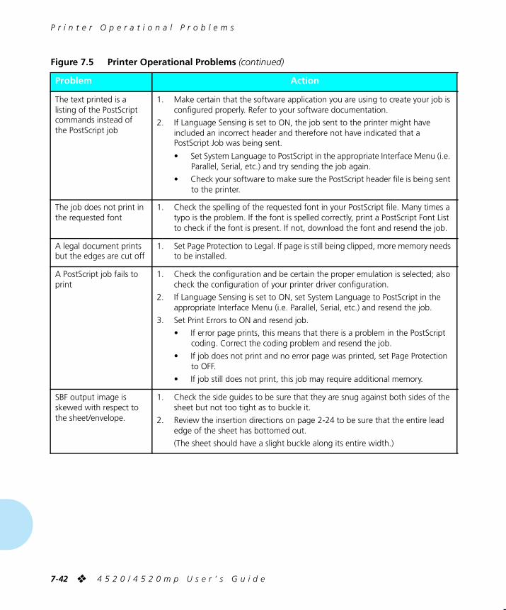
P r i n t e r O p e r a t i o n a l P r o b l e m s
7-42
❖
4 5 2 0 / 4 5 2 0 m p U s e r ’ s G u i d e
The text printed is a listing of the PostScript commands instead of the PostScript job
1. Make certain that the software application you are using to create your job is configured properly. Refer to your software documentation.
2. If Language Sensing is set to ON, the job sent to the printer might have included an incorrect header and therefore not have indicated that a PostScript Job was being sent.
• Set System Language to PostScript in the appropriate Interface Menu (i.e. Parallel, Serial, etc.) and try sending the job again.
• Check your software to make sure the PostScript header file is being sent to the printer.
The job does not print in the requested font
1. Check the spelling of the requested font in your PostScript file. Many times a typo is the problem. If the font is spelled correctly, print a PostScript Font List to check if the font is present. If not, download the font and resend the job.
A legal document prints but the edges are cut off
1. Set Page Protection to Legal. If page is still being clipped, more memory needs to be installed.
A PostScript job fails to print
1. Check the configuration and be certain the proper emulation is selected; also check the configuration of your printer driver configuration.
2. If Language Sensing is set to ON, set System Language to PostScript in the appropriate Interface Menu (i.e. Parallel, Serial, etc.) and resend the job.
3. Set Print Errors to ON and resend job.
• If error page prints, this means that there is a problem in the PostScript coding. Correct the coding problem and resend the job.
• If job does not print and no error page was printed, set Page Protection to OFF.
• If job still does not print, this job may require additional memory.
SBF output image is skewed with respect to the sheet/envelope.
1. Check the side guides to be sure that they are snug against both sides of the sheet but not too tight as to buckle it.
2. Review the insertion directions on page 2-24 to be sure that the entire lead edge of the sheet has bottomed out.
(The sheet should have a slight buckle along its entire width.)
Figure 7.5 Printer Operational Problems
(continued)
Problem
Action
WUG-CH07 Page 42 Black,Red,Cyan Wednesday, January 25, 1995 3:45 PM

P r i n t Q u a l i t y P r o b l e m s
C h a p t e r 7 : T r o u b l e s h o o t i n g
❖
7-43
Figure 7.6 lists common print quality problems, the likely cause, and recommended actions.
Figure 7.6 Print Quality Problems
Problem
Possible Causes
Corrective Actions
Light/faint prints
Overall image is lighter than normal.
1. Tone level low/empty
2. Print Density adjustment set too low
3. Damp paper stock
4. Transfer Corotron wire broken/dirty
1. Replace EP cartridge.
2. Adjust Print Density (see
Chapter 6
).
3. Replace paper stock.
4. Replace Transfer Corotron (see
Chapter 6
).
Blank Prints
Entire printed page is blank with no visible print.
1. EP Cartridge insert is still in place
2. Defective EP cartridge
3. Multiple sheets are being fed from the paper tray at the same time.
4. No printable data received from computer
1. Remove the paper insert (see
Chapter 6
).
2. Replace EP cartridge.
3. Remove paper from paper tray and fan it. Ensure that paper is correctly loaded in tray with edges under metal corners (see
Chapter 2
).
4. Produce a Test Print (see
Chapter 3
). If the Test Print is normal, check the following:
• Interface cable between computer and printer
• Printer set up and application software
If the Test Print is blank, contact your dealer or Xerox / Rank Xerox.
Print QualityProblems
WUG-CH07 Page 43 Black,Red,Cyan Wednesday, January 25, 1995 3:45 PM

P r i n t Q u a l i t y P r o b l e m s
7-44
❖
4 5 2 0 / 4 5 2 0 m p U s e r ’ s G u i d e
Background/black prints
Overall darkness or localized dark bands in the non-image areas.
1. Defective EP cartridge
2. Print Density adjustment set too high
3. Defective Laser, Controller, Fuser Assembly
1. Replace EP cartridge.
2. Adjust Print Density (see
Chapter 6
).
3. Contact your dealer or Xerox / Rank Xerox.
Spot deletions
Areas of the print are extremely light or missing.
1. Damp paper stock
2. Defective EP cartridge
1. Replace paper stock.
2. Replace EP cartridge.
Figure 7.6 Print Quality Problems
(continued)
Problem
Possible Causes
Corrective Actions
WUG-CH07 Page 44 Black,Red,Cyan Wednesday, January 25, 1995 3:45 PM

P r i n t Q u a l i t y P r o b l e m s
C h a p t e r 7 : T r o u b l e s h o o t i n g
❖
7-45
Vertical line deletions
Localized print deletions forming narrow lines running in the direction of paper movement.
1. Defective EP cartridge
2. Defective paper stock, creases, folds, etc.
3. Transfer Corotron wire dirty
1. Replace EP cartridge.
2. Replace paper stock.
3. Replace Transfer Corotron (see
Chapter 6
).
Horizontal line deletions
Localized print deletions appearing as bands running across the page perpendicular to the direction of paper movement.
1. Defective EP cartridge
2. Defective paper stock, creases, folds, etc.
1. Replace EP cartridge.
2. Replace paper stock.
Figure 7.6 Print Quality Problems
(continued)
Problem
Possible Causes
Corrective Actions
WUG-CH07 Page 45 Black,Red,Cyan Wednesday, January 25, 1995 3:45 PM

P r i n t Q u a l i t y P r o b l e m s
7-46
❖
4 5 2 0 / 4 5 2 0 m p U s e r ’ s G u i d e
Vertical dark streaks
Black lines running across the print in the direction of paper movement.
1. Defective EP cartridge
2. Contaminated paper path
3. Contaminated Fuser Rolls or Wiper
1. Replace EP cartridge.
2. Clean paper path to remove any toner accumulations.
3. Replace Fuser Wiper (see
Chapter 6
). If problem is not resolved, contact your dealer or Xerox / Rank Xerox.
Horizontal dark streaks
Black lines running across the page perpendicular to the direction of paper movement.
1. Defective EP cartridge
2. Contaminated paper path
3. Contaminated Fuser Rolls or Wiper
1. Replace EP cartridge.
2. Clean paper path to remove any toner accumulations.
3. Replace Fuser Wiper (see
Chapter 6
). If problem is not resolved, contact your dealer or Xerox / Rank Xerox.
Figure 7.6 Print Quality Problems
(continued)
Problem
Possible Causes
Corrective Actions
WUG-CH07 Page 46 Black,Red,Cyan Wednesday, January 25, 1995 3:45 PM

P r i n t Q u a l i t y P r o b l e m s
C h a p t e r 7 : T r o u b l e s h o o t i n g
❖
7-47
Dark spots/marks
1. Defective EP cartridge
2. Contaminated paper path
3. Contaminated Fuser Rolls or Wiper
1. Replace EP cartridge.
2. Clean paper path to remove any toner accumulations.
3. Replace Fuser Wiper (see
Chapter 6
). If problem is not resolved, contact your dealer or Xerox / Rank Xerox.
Residual image
Ghost images of previous pages is produced along with the current page.
1. Defective EP cartridge
2. Contaminated Fuser Rolls or Wiper
1. Replace EP cartridge.
2. Replace Fuser Wiper (see
Chapter 6
). If problem is not resolved, contact your dealer or Xerox / Rank Xerox.
Figure 7.6 Print Quality Problems
(continued)
Problem
Possible Causes
Corrective Actions
WUG-CH07 Page 47 Black,Red,Cyan Wednesday, January 25, 1995 3:45 PM

P r i n t Q u a l i t y P r o b l e m s
7-48
❖
4 5 2 0 / 4 5 2 0 m p U s e r ’ s G u i d e
Unfused or partially fused image
The printed image is not fully fused to the paper and easily rubs off.
1. Damp paper stock
2. Heavy or unusual paper stock
3. Light image density
4. Defective Fuser Module
1. Replace paper stock.
2. Refer to
Chapter 2
for printer throughput capabilities.
3. Replace EP cartridge.
4. Contact your dealer or Xerox / Rank Xerox.
Skewed prints
Printed image is not parallel to the edge of the paper.
1. Paper improperly loaded into paper tray
2. Obstructed paper path
3. Contaminated paper path
4. Dirty/worn Paper Feed Rolls
1. Check trays for proper paper loading (see
Chapter 2
).
2. Inspect paper path for obstructions (torn pieces of paper, etc.).
3. Inspect/clean paper path to remove residual toner and paper dust.
4. Contact your dealer or Xerox / Rank Xerox.
Figure 7.6 Print Quality Problems
(continued)
Problem
Possible Causes
Corrective Actions
WUG-CH07 Page 48 Black,Red,Cyan Wednesday, January 25, 1995 3:45 PM

P r i n t Q u a l i t y P r o b l e m s
C h a p t e r 7 : T r o u b l e s h o o t i n g
❖
7-49
Image misregistration
The printed image is mispositioned on the page.
.
1. Paper improperly loaded into paper tray
2. Wrong paper size for application
3. Paper loaded into tray in the wrong orientation
1. Check trays for proper paper loading (see
Chapter 2
).
2. Check paper stock and printer configuration.
3. Check trays for proper paper loading (see
Chapter 2
).
If problem is not resolved, contact your dealer or Xerox / Rank Xerox.
Produce a Test Print (see
Chapter 3
)
• Fold and crease the Test Print as shown.
• Both horizontal and vertical folds should fall within the area defined by the first set of large tick marks on either side of the center cross target.
If the pattern registers OK, the problem may be in your software application.
If the pattern is not properly registered, contact your dealer or Xerox / Rank Xerox.
Figure 7.6 Print Quality Problems
(continued)
Problem
Possible Causes
Corrective Actions
WUG-CH07 Page 49 Black,Red,Cyan Wednesday, January 25, 1995 3:45 PM

P r i n t Q u a l i t y P r o b l e m s
7-50
❖
4 5 2 0 / 4 5 2 0 m p U s e r ’ s G u i d e
Damaged prints
Prints are wrinkled, creased, or torn.
1. Poor paper condition
2. Paper improperly loaded into paper tray
3. Obstructed paper path
4. Defective Fuser Module
1. Inspect/replace paper stock.
2. Check trays for proper paper loading (see
Chapter 2
).
3. Inspect paper path for obstructions (torn pieces of paper, etc.).
4. Contact your dealer or Xerox / Rank Xerox.
Figure 7.6 Print Quality Problems
(continued)
Problem
Possible Causes
Corrective Actions
WUG-CH07 Page 50 Black,Red,Cyan Wednesday, January 25, 1995 3:45 PM

P r i n t Q u a l i t y P r o b l e m s
C h a p t e r 7 : T r o u b l e s h o o t i n g
❖
7-51
ˆ
TrueRes Smoothing problems
TrueRes Smoothing is a technology that smooths the jagged edges of curved or near vertical/horizontal lines.
Produce Test Prints (see
Chapter 3
) with TrueRes switched both ON and OFF. Inspect the TrueRes target on the Test Print: If:
1. TrueRes is not functional (no apparent difference between ON and OFF setting)
2. TrueRes appears excessively dark:
or
TrueRes appears insufficient
1. Failed Controller
2. Print Density set too dark/light
1. Replace Controller.
Contact your dealer or Xerox / Rank Xerox.
2. Adjust Print Density (see
Chapter 6
).
Figure 7.6 Print Quality Problems
(continued)
Problem
Possible Causes
Corrective Actions
WUG-CH07 Page 51 Black,Red,Cyan Wednesday, January 25, 1995 3:45 PM

7-52
❖
4 5 2 0 / 4 5 2 0 m p U s e r ’ s G u i d e
WUG-CH07 Page 52 Black,Red Wednesday, January 25, 1995 3:45 PM

Appendix A
A p p e n d i x A : P r i n t e r a n d C a b l e S p e c i f i c a t i o n s
❖
A-1
Printer and Cable Specifications
Appendix A
Printer Specifications
...........................................................
A-2
Cable Specifications
.............................................................
A-5
Parallel Interface A-5
RS-232C Serial Interface (CCITT V.24) A-8Data Rates A-8Encoding A-8Protocols A-8Connections A-8
RS-422A Serial Interface (CCITT V.11 and X.27) A-10Data Rates A-10Encoding A-10Protocols A-10Connections A-10
Network Interface A-12
Null Modem A-12
WUG-APPA Page 1 Black,Cyan Sunday, January 22, 1995 8:55 PM

P r i n t e r S p e c i f i c a t i o n s
A-2
❖
4 5 2 0 / 4 5 2 0 m p U s e r ’ s G u i d e
Imaging method
Electro-Photography
Exposure system
Semiconductor laser beam (laser diode) scanning
Image resolution
800 x 800, 600 x 600, 400 x 400, and 300 x 300 dpi
Warm up time
Less than 60 seconds after power on
Continuous print speed
20 ppm (pages per minute)
Processor
25 MHz AMD 29030 RISC
Maximum Monthly Duty Cycle
Up to 50,000 prints
Nominal voltage
220/240 V
110/115 V
Nominal frequency
50/60 Hz
Power consumption
Less than 450 W during operation; power saver mode operational after 60 minutes of not printing
Noise level
53 dB continuous sound and 65 dB impulse sound during operation; less than 40 dB in standby
Temperature
10
°
C / 50
°
F to 35
°
C / 95
°
F during operation
Humidity
15% to 85% during operation
Dimensions
51.9 x 41 x 53.3 cm
16.4 x 20 x 21 inches
Weight
35 Kgs / 77 lbs
Maximum Memory Capacity
52 MB
PrinterSpecifications
WUG-APPA Page 2 Black,Cyan Sunday, January 22, 1995 8:55 PM

P r i n t e r S p e c i f i c a t i o n s
A p p e n d i x A : P r i n t e r a n d C a b l e S p e c i f i c a t i o n s
❖
A-3
Factory-provided features
4 MB printer memory
Three 250-sheet paper trays
Single-sheet bypass feeder (SBF)
EP (electronic printing) cartridge
Output tray wire guide
Power cord (110 volt printers only)
Document Services for Printing
software diskettes
User documentation
On the 4520mp printer:
Additional
4 MB SIMM
(for a total of 8 MB)
PostScript option
Ethernet network interface card (XNIC-E’NET)
Options
4 MB SIMM
16 MB SIMM
Multi-sheet Bypass Feeder (MBF)
High-Capacity Feeder (HCF)
High-Capacity Envelope Feeder (HCEF)
Paper trays (in a variety of sizes)
PostScript kit
Ethernet network interface card (XNIC-E’NET)
LocalTalk network interface card (XNIC-L’TALK)
Token Ring network interface card (XNIC-T’RING)
125 MB hard disk
PCL font cards
See Appendix D: Ordering Information
for more
information about ordering options.
Printable Area
See Figure A.1 for printable area dimensions. (The printer cannot print outside the printable area.)
Note
WUG-APPA Page 3 Black,Cyan Sunday, January 22, 1995 8:55 PM

P r i n t e r S p e c i f i c a t i o n s
A-4
❖
4 5 2 0 / 4 5 2 0 m p U s e r ’ s G u i d e
Figure A.1 PCL and PostScript printable area dimensions
Printer Language
Paper Size
Printable Area Width
Printable Area Length
PCL
All paper sizes Determined by the formula: W – 8.5 mm
(or W – .33 inch) where W = physical paper width
Determined by the formula: L – 8.5 mm
(or L – .33 inch) whereL = physical paper width
PostScript
A4 200 mm7.89 inches
289 mm11.36 inches
8.5 x 11 (Letter) 207 mm8.11 inches
271 mm10.67 inches
Executive 175 mm6.93 inches
258 mm10.17 inches
8.5 x 14 (Legal) 207 mm8.11 inches
347 mm13.67 inches
Com-10 96 mm3.73 inches
233 mm9.17 inches
DL 100 mm3.95 inches
212 mm8.33 inches
Folio 207 mm8.11 inches
347 mm12.67 inches
A5 141 mm5.55 inches
200 mm7.89 inches
B5 (ISO) 167 mm6.61 inches
241 mm9.53 inches
C5 154 mm6.08 inches
220 mm8.68 inches
WUG-APPA Page 4 Black,Cyan Sunday, January 22, 1995 8:55 PM

C a b l e S p e c i f i c a t i o n s
A p p e n d i x A : P r i n t e r a n d C a b l e S p e c i f i c a t i o n s
❖
A-5
Figure A.2 shows parallel and serial interface information to help you obtain the correct printer cable.
Today most single-user computer systems (IBM PC and compatibles) utilize the parallel interface because it allows more data at a time to be transferred from the computer to the printer than does a serial interface. If the printer is not connected to a network, printing through the parallel interface is most desirable.
The printers support a bidirectional parallel port, compatible with the IEEE standard 1284-B, with forward transfer rates of 100 KBytes or 1 MBytes.
The FAULT signal (pin no. 32) goes true (low) under the following conditions:
• Off-line mode selected
• Cover open (interlock open)
• Paper out
• Paper jam
• Any machine fault
† Xerox has certified Parallel cables with these printers at a maximum of 6 feet.‡ Xerox has certified Serial cables with these printers at a maximum of 4 feet.
Figure A.2 4520/4520mp parallel and serial cable characteristics
Type
Commonly Used for
Communication Protocol
Printer Connector Type
Standard Centronics Parallel
†
CableMost PC systems today Bidirectional
(Centronics standard)36-pin male
Standard Serial
‡
Cable PCs and modems RS-232CorRS-422A
25-pin male
CableSpecifications
Parallel Interface
WUG-APPA Page 5 Black,Cyan Sunday, January 22, 1995 8:55 PM

C a b l e S p e c i f i c a t i o n s
A-6
❖
4 5 2 0 / 4 5 2 0 m p U s e r ’ s G u i d e
The FAULT signal goes false (high) when all the above conditions are corrected.
The Centronics bidirectional parallel interface is designed to provide plug-to-plug compatibility with a 36 pin Amphenol 57-40360 (or equivalent) connector that connects to an Amphenol 57-30360 (or equivalent) connector. The cable length has been certified at 6 feet, and will be the twisted pair type 22AWG -15 pairs. Pin assignment and functions for the Centronics interface are designated in Figure A.3.
Figure A.3 Centronics connector pin assignment
Signal Pin #
Signal Name
Source
Function
1 /STROBE HOST Host Check
2 DATA 0 BIDIRECTIONAL Data Bit 0
3 DATA 1 BIDIRECTIONAL Data Bit 1
4 DATA 2 BIDIRECTIONAL Data Bit 2
5 DATA 3 BIDIRECTIONAL Data Bit 3
6 DATA 4 BIDIRECTIONAL Data Bit 4
7 DATA 5 BIDIRECTIONAL Data Bit 5
8 DATA 6 BIDIRECTIONAL Data Bit 6
9 DATA 7 BIDIRECTIONAL Data Bit 7
10 /ACK PRINTER Printer Acknowledge
11 BUSY PRINTER Printer Busy
12 PE PRINTER Out of Paper
13 SELECT PRINTER Printer Select
14 /AUTOFEED HOST Host Busy
15 N/C - - - - - - Not Defined
16 GND Logic GND
17 GND Chassis GND
WUG-APPA Page 6 Black,Cyan Sunday, January 22, 1995 8:55 PM

C a b l e S p e c i f i c a t i o n s
A p p e n d i x A : P r i n t e r a n d C a b l e S p e c i f i c a t i o n s
❖
A-7
18 + 5V PRINTER Printer Logic High
19 GND Signal GND (
/Strobe
)
20 GND Signal GND (
Data 0
)
21 GND Signal GND (
Data 1
)
22 GND Signal GND (
Data 2
)
23 GND Signal GND (
Data 3
)
24 GND Signal GND (
Data 4
)
25 GND Signal GND (
Data 5
)
26 GND Signal GND (
Data 6
)
27 GND Signal GND (
Data 7
)
28 GND Signal Ground (
PE, SELECT, /ACK
)
29 GND Signal Ground (
BUSY, /FAULT
)
30 GND Signal Ground (
AUTOFEED, /SELECTIN, /INIT
)
31 /INIT HOST Reset Signal
32 /FAULT PRINTER Machine Status
33 - 35 N/C - - - - - - Not Defined
36 /SELECTIN HOST Select Input
Figure A.3 Centronics connector pin assignment
(continued)
Signal Pin #
Signal Name
Source
Function
WUG-APPA Page 7 Black,Cyan Sunday, January 22, 1995 8:55 PM

C a b l e S p e c i f i c a t i o n s
A-8
❖
4 5 2 0 / 4 5 2 0 m p U s e r ’ s G u i d e
The RS-232C Serial Interface complies with the EIA 232C standard which defines the interconnect of Data Terminal Equipment (DTE) and Data Communication Equipment (DCE).
Data Rates
The user may select line speeds of 300, 600, 1200, 2400, 4800, 9600, 19200 and 38400 baud.
Default setting is for 9600 baud
.
Encoding
Asynchronous communication in the printers supports 7 or 8-bit ASCII data. The string of data bits is encapsulated by 1 Start bit, 1 or 2 Stop bits and may have an appended Parity bit. Parity (even, odd or none), the number of stop bits and 7 or 8 bit data are selectable from the front panel UI.
Default settings are for 8 bit data with 1 stop bit and parity none
.
Protocols
Character protocols are used to regulate the flow of information between machine and host. The software handshaking protocol of XON/XOFF, Robust XON/XOFF, and DTR Polarity are available – DTR provides the hardware handshaking.
The default setting is for Robust XON/XOFF
.
Connections
The connector for the RS-232 interface is the 25 pin “D” Shell type. The use of short cables for interconnect is recommended. Cable length has been certified at 4 feet.
RS-232C SerialInterface (CCITT
V.24)
WUG-APPA Page 8 Black,Cyan Sunday, January 22, 1995 8:55 PM

C a b l e S p e c i f i c a t i o n s
A p p e n d i x A : P r i n t e r a n d C a b l e S p e c i f i c a t i o n s
❖
A-9
The interface signals and their associated pin assignments are identified in the Figure A.4.
Figure A.4 Pin assignment for RS-232C
Signal Name
Pin #
RS-232C Function
Direction
Chassis GND 1 GND - - - - - -
Transmitted Data 2 Data From Printer
Received Data 3 Data To Printer
Request to Send 4 Control From Printer
Clear to Send 5 Control To Printer
Data Set Ready 6 Control To Printer
Signal GND 7 GND - - - - - -
Carrier Detect 8 Control To Printer
N/C 9, 10, 12 - - - - - - - - - - - -
Send Data Noninverted 11 - - - - - - - - - - - -
Receive Data Noninverted 13 - - - - - - - - - - - -
Send Data inverted 14 - - - - - - - - - - - -
N/C 15, 17 – 19 - - - - - - - - - - - -
Receive Data Inverted 16 - - - - - - - - - - - -
Data Terminal Ready 20 Control From Printer
N/C 21 – 25 - - - - - - - - - - - -
WUG-APPA Page 9 Black,Cyan Sunday, January 22, 1995 8:55 PM

C a b l e S p e c i f i c a t i o n s
A-10
❖
4 5 2 0 / 4 5 2 0 m p U s e r ’ s G u i d e
The RS-422A Serial Interface is hardware compatible with the EIA RS-422 standard which defines the interconnect of Data Terminal Equipment (DTE) and Data Communication Equipment (DCE).
Data Rates
The user may select line speeds of 300, 600, 1200, 2400, 4800, 9600, 19200 and 38400 baud.
Default setting is for 9600 baud
.
Encoding
Asynchronous communication in the printers supports 7 or 8-bit ASCII data. The string of data bits is encapsulated by 1 Start bit, 1 or 2 Stop bits and may have an appended Parity bit. Parity (even, odd or none), the number of stop bits and 7 or 8 bit data are selectable from the front panel UI.
Default settings are for 8 bit data with 1 stop bit and parity none
.
Protocols
XON/XOFF provides the software handshaking on the RS-422 interface.
Robust XON/XOFF
is the default
.
Connections
The connector for the RS-422A interface is the 25 pin “D” Shell type. The use of short cables for interconnect is recommended. Cable length has been certified at 4 feet.
RS-422A SerialInterface (CCITT
V.11 and X.27)
WUG-APPA Page 10 Black,Cyan Sunday, January 22, 1995 8:55 PM

C a b l e S p e c i f i c a t i o n s
A p p e n d i x A : P r i n t e r a n d C a b l e S p e c i f i c a t i o n s
❖
A-11
The interface signals and their associated pin assignments are identified in the Figure A.5.
Figure A.5 Pin assignment for RS-422A
Signal Name
Pin #
RS-422A Function
Direction
Chassis GND 1 GND - - - - - -
Transmitted Data 2 - - - - - - - - - - - -
Received Data 3 - - - - - - - - - - - -
Request to Send 4 - - - - - - - - - - - -
Clear to Send 5 - - - - - - - - - - - -
Data Set Ready 6 - - - - - - - - - - - -
Signal GND 7 GND - - - - - -
Carrier Detect 8 - - - - - - - - - - - -
N/C 9, 10, 12 - - - - - - - - - - - -
Send Data Noninverted 11 Data From Printer
Receive Data Noninverted 13 Data To Printer
Send Data inverted 14 Data From Printer
N/C 15, 17 – 19 - - - - - - - - - - - -
Receive Data Inverted 16 Data To Printer
Data Terminal Ready 20 - - - - - - - - - - - -
N/C 21 – 25 - - - - - - - - - - - -
WUG-APPA Page 11 Black,Cyan Sunday, January 22, 1995 8:55 PM

C a b l e S p e c i f i c a t i o n s
A-12
❖
4 5 2 0 / 4 5 2 0 m p U s e r ’ s G u i d e
A null modem is a device that eliminates both a modem and a telephone line. When the printers are used with an asynchronous serial interface connected to a DTE host (such as a PC-compatible), a modem, modem eliminator, or a null modem is required. Figure A.6 shows null modem wiring.
Figure A.6 Null Modem wiring
Network interface communication is the most common for enabling multiple users to print from a host system.
For
network interface
cables, refer to your network software documentation.
Null Modem
Network Interface
WUG-APPA Page 12 Black,Cyan Sunday, January 22, 1995 8:55 PM

Appendix B
A p p e n d i x B : P r i n t e r C o m m a n d s ( E s c a p e S e q u e n c e s )
❖
B-1
Printer Commands (Escape Sequences)
Appendix B
Xerox-Unique Settings
.........................................................
B-2
PCL Printer Commands
.........................................................
B-3
HP-GL/2 Context Printer Commands
.................................
B-21
Control Codes
.....................................................................
B-25
WUG-APPB Page 1 Black,Cyan Sunday, January 22, 1995 9:01 PM

X e r o x - U n i q u e S e t t i n g s
B-2
❖
4 5 2 0 / 4 5 2 0 m p U s e r ’ s G u i d e
In addition to the standard PCL printer commands, Xerox has added some unique settings in the following areas:
• Paper Source
See the PAGE CONTROL COMMANDS Paper Source
section (page B-4) for the full range of paper sources for Xerox printers.
• Page Size
See the PAGE CONTROL COMMANDS Page Size section (page B-4) for the full range of paper sizes for Xerox printers.
• Resolution
See the GRAPHICS Raster Resolution section (page B-14)
for all resolutions available.
Xerox-UniqueSettings
WUG-APPB Page 2 Black,Cyan Sunday, January 22, 1995 9:01 PM

P C L P r i n t e r C o m m a n d s
A p p e n d i x B : P r i n t e r C o m m a n d s ( E s c a p e S e q u e n c e s )
❖
B-3
PCL printer commands—also called
escape sequences
—are used by software applications to
control how fonts and graphics are printed on the page
. Figure B.1 lists the PCL printer commands for the 4520/4520mp printers.
Figure B.1 PCL printer commands
Function
Parameter
Command
Decimal Value
Hexadecimal Value
JOB CONTROL COMMANDS
Reset
Universal Exit Language (ULE)
—
EC
%-12345X 027 037 045 049 050 051 052 053 088
1B 25 2D 31 32 33 34 35 58
Reset —
EC
E 027 069 1B 45
Number Of Copies
# of Copies
EC
&l#X 027 038 108 # ... # 088 1B 26 6C # ... # 58
Long Edge (Left) Offset Registration
# of Decipoints (1/720”)
EC
&l#U 027 038 108 # ... # 085 1B 26 6C # ... # 55
Short Edge (Top) Offset Registration
# of Decipoints (1/720”)
EC
&l#Z 027 038 108 # ... # 090 1B 26 6C # ... # 5A
Unit Of Measure
# = Number of units per inch
EC
&u#D 027 038 117 # ... # 068 1B 26 75 # ... # 44
PCL PrinterCommands
WUG-APPB Page 3 Black,Cyan Sunday, January 22, 1995 9:01 PM

P C L P r i n t e r C o m m a n d s
B-4
❖
4 5 2 0 / 4 5 2 0 m p U s e r ’ s G u i d e
PAGE CONTROL COMMANDS
Page Length and Size
Paper Source Eject Page
EC
&l0H 027 038 108 048 072 1B 26 6C 30 48
Main Paper Source (Upper)
EC
&l1H 027 038 108 049 072 1B 26 6C 31 48
Manual Feed
EC
&l2H 027 038 108 050 072 1B 26 6C 32 48
Manual Envelope Feed
EC
&l3H 027 038 108 051 072 1B 26 6C 33 48
Alternate Paper Source (Lower)
EC
&l4H 027 038 108 052 072 1B 26 6C 34 48
Optional Large Paper Source (HCF)
EC
&l5H 027 038 108 053 072 1B 26 6C 35 48
Envelope Feeder (HCEF)
EC
&l6H 027 038 108 054 072 1B 26 6C 36 48
Middle
EC
&l7H 027 038 108 055 072 1B 26 6C 37 48
Page Size Executive
EC
&l1A 027 038 108 049 065 1B 26 6C 31 41
Letter
EC
&l2A 027 038 108 050 065 1B 26 6C 32 41
Legal
EC
&l3A 027 038 108 051 065 1B 26 6C 33 41
Ledger
EC
&l6A 027 038 108 054 065 1B 26 6C 36 41
A5
EC
&l70A 027 038 108 055 048 065
1B 26 6C 37 30 41
A4
EC
&l26A 027 038 108 050 054 065
1B 26 6C 32 36 41
A3
EC
&l27A 027 038 108 050 055 065
1B 26 6C 32 37 41
Folio
EC
&l71A 027 038 108 055 049 065
1B 26 6C 37 31 41
COM 10
EC
&l81A 027 038 108 056 049 065
1B 26 6C 38 31 41
Figure B.1 PCL printer commands
(continued)
Function
Parameter
Command
Decimal Value
Hexadecimal Value
WUG-APPB Page 4 Black,Cyan Sunday, January 22, 1995 9:01 PM

P C L P r i n t e r C o m m a n d s
A p p e n d i x B : P r i n t e r C o m m a n d s ( E s c a p e S e q u e n c e s )
❖
B-5
DL
EC
&l90A 027 038 108 057 048 065
1B 26 6C 39 30 41
C5
EC
&l91A 027 038 108 057 049 065
1B 26 6C 39 31 41
B5
EC
&l100A 027 038 108 049 048 048 065
1B 26 6C 31 30 30 41
B4
EC
&l72A 027 038 108 055 050 065
1B 26 6C 37 32 41
Page Length # of Lines (5-128)
EC
&l#P 027 038 108 #...# 080 1B 26 6C #...# 050
Orientation
Orientation Portrait
EC
&l0O 027 038 108 048 079 1B 26 6C 30 4F
Landscape
EC
&l1O 027 038 108 049 079 1B 26 6C 31 4F
Reverse Portrait
EC
&l2O 027 038 108 050 079 1B 26 6C 32 4F
Reverse Landscape
EC
&l3O 027 038 108 051 079 1B 26 6C 33 4F
Print Direction # Degrees of Rotation (counter-clockwise. 90
°
increments only)
EC
&a#P 027 038 097 # ... # 080 1B 26 61 # ... # 50
Margins and Text Length
Top Margin # of Lines
EC
&l#E 027 038 108 # ... # 069 1B 26 6C # ... # 45
Text Length # of Lines
EC
&l#F 027 038 108 # ... # 070 1B 26 6C # ... # 46
Left Margin # of Columns
EC
&a#L 027 038 097 # ... # 076 1B 26 61 # ... # 4C
Right Margin # of Columns
EC
&a#M 027 038 097 # ... # 077 1B 26 61 # ... # 4D
Clear Horizontal Margins
—
EC
9 027 057 1B 39
Perforation Skip Mode
Perforation Skip Disable
EC
&l0L 027 038 108 048 076 1B 26 6C 30 4C
Enable
EC
&l1L 027 038 108 049 076 1B 26 6C 31 4C
Figure B.1 PCL printer commands
(continued)
Function
Parameter
Command
Decimal Value
Hexadecimal Value
WUG-APPB Page 5 Black,Cyan Sunday, January 22, 1995 9:01 PM

P C L P r i n t e r C o m m a n d s
B-6
❖
4 5 2 0 / 4 5 2 0 m p U s e r ’ s G u i d e
Horizontal Column Spacing
Horizontal Motion Index (HMI)
# of 1/120” Increments
EC
&k#H 027 038 107 # ... # 072 1B 26 6B # ... # 48
Vertical Line Spacing
Vertical Motion Index (VMI)
# of 1/48” Increments
EC
&l#C 027 038 108 # ... # 067 1B 26 6C # ... # 43
Line Spacing (Lines per inch)
1 line/inch
EC
&l1D 027 038 108 049 068 1B 26 6C 31 44
2 lines/inch
EC
&l2D 027 038 108 050 068 1B 26 6C 32 44
3 lines/inch
EC
&l3D 027 038 108 051 068 1B 26 6C 33 44
4 lines/inch
EC
&l4D 027 038 108 052 068 1B 26 6C 34 44
6 lines/inch
EC
&l6D 027 038 108 054 068 1B 26 6C 36 44
8 lines/inch
EC
&l8D 027 038 108 056 068 1B 26 6C 38 44
12 lines/inch
EC
&l12D 027 038 108 049 050 068
1B 26 6C 31 32 44
16 lines/inch
EC
&l16D 027 038 108 049 054 068
1B 26 6C 31 36 44
24 lines/inch
EC
&l24D 027 038 108 050 052 068
1B 26 6C 32 34 44
48 lines/inch
EC
&l48D 027 038 108 052 056 068
1B 26 6C 34 38 44
CURSOR POSITIONING
Vertical and Horizontal
Vertical Position # of Rows
EC
&a#R 027 038 097 # ... # 082 1B 26 61 # ... # 52
# of Units
EC
*p#Y 027 042 112 # ... # 089 1B 2A 70 # ... # 59
# of Decipoints
EC
&a#V 027 038 097 # ... # 086 1B 26 61 # ... # 56
Figure B.1 PCL printer commands
(continued)
Function
Parameter
Command
Decimal Value
Hexadecimal Value
WUG-APPB Page 6 Black,Cyan Sunday, January 22, 1995 9:01 PM

P C L P r i n t e r C o m m a n d s
A p p e n d i x B : P r i n t e r C o m m a n d s ( E s c a p e S e q u e n c e s )
❖
B-7
Horizontal Position
# of Columns
EC
&a#C 027 038 097 # ... # 067 1B 26 61 # ... # 43
# of Units
EC
*p#X 027 042 112 # ... # 088 1B 2A 70 # ... # 58
# of Decipoints
EC
&a#H 027 038 097 # ... # 072 1B 26 61 # ... # 48
Half Line Feed
EC
= 027 061 1B 3D
End-of-Line Termination
Line Termination
CR=CR; LF=LF; FF=FF
EC
&k0G 027 038 107 048 071 1B 26 6B 30 47
CR=CR+LF; LF=LF; FF=FF
EC
&k1G 027 038 107 049 071 1B 26 6B 31 47
CR=CR; LF=CR+LF; FF=CR+FF
EC
&k2G 027 038 107 050 071 1B 26 6B 32 47
CR=CR+LF; LF=CR+LF; FF=CR+FF
EC
&k3G 027 038 107 051 071 1B 26 6B 33 47
Push/Pop Position
Push/Pop Position
Push
EC
&f0S 027 038 102 048 083 1B 26 66 30 53
Pop
EC
&f1S 027 038 102 049 083 1B 26 66 31 53
FONT SELECTION
Symbol Set Selection
Primary Symbol Set
ISO 60: Norwegian 1
EC
(0D 027 040 048 068 1B 28 30 44
ISO 4: United Kingdom
EC
(1E 027 040 049 069 1B 28 31 45
Windows 3.1 Latin 2
EC
(9E 027 040 057 069 1B 28 39 45
ISO 69: French
EC
(1F 027 040 049 070 1B 28 31 46
ISO 21: German
EC
(1G 027 040 049 071 1B 28 31 47
ISO 15: Italian
EC
(0I 027 040 048 073 1B 28 30 49
Figure B.1 PCL printer commands
(continued)
Function
Parameter
Command
Decimal Value
Hexadecimal Value
WUG-APPB Page 7 Black,Cyan Sunday, January 22, 1995 9:01 PM

P C L P r i n t e r C o m m a n d s
B-8
❖
4 5 2 0 / 4 5 2 0 m p U s e r ’ s G u i d e
Microsoft Publishing
EC
(6J 027 040 054 074 1B 28 36 4A
DeskTop
EC
(7J 027 040 055 074 1B 28 37 4A
PS Text
EC
(10J 027 040 049 048 074 1B 28 31 30 4A
MC Text
EC
(12J 027 040 049 050 074 1B 28 31 32 4A
Ventura International
EC
(13J 027 040 049 051 074 1B 28 31 33 4A
Ventura US
EC
(14J 027 040 049 052 074 1B 28 31 34 4A
Wingdings
EC
(579L 027 040 053 055 057 076
1B 28 35 37 39 4C
PS Math
EC
(5M 027 040 053 077 1B 28 35 4D
Ventura Math
EC
(6M 027 040 054 077 1B 28 36 4D
Math-8
EC
(8M 027 040 056 077 1B 28 38 4D
Symbol
EC
(19M 027 040 049 057 077 1B 28 31 39 4D
ISO 8859-1 (ECMA-94) Latin 1
EC
(0N 027 040 048 078 1B 28 30 4E
ISO 8859-2 Latin 2
EC
(2N 027 040 050 078 1B 28 32 4E
ISO 8859-9 Latin 5
EC
(5N 027 040 053 078 1B 28 35 4E
ISO 11: Swedish
EC
(0S 027 040 048 083 1B 28 30 53
ISO 17: Spanish
EC
(2S 027 040 050 083 1B 28 32 53
Windows 3.1 Latin 5
EC
(5T 027 040 053 084 1B 28 35 54
PC Turkish
EC
(9T 027 040 057 084 1B 28 39 54
ISO 6: ASCII
EC
(0U 027 040 048 085 1B 28 30 55
Legal
EC
(1U 027 040 049 085 1B 28 31 55
Roman-8
EC
(8U 027 040 056 085 1B 28 38 55
Windows 3.0 Latin 1
EC
(9U 027 040 057 085 1B 28 39 55
Figure B.1 PCL printer commands
(continued)
Function
Parameter
Command
Decimal Value
Hexadecimal Value
WUG-APPB Page 8 Black,Cyan Sunday, January 22, 1995 9:01 PM

P C L P r i n t e r C o m m a n d s
A p p e n d i x B : P r i n t e r C o m m a n d s ( E s c a p e S e q u e n c e s )
❖
B-9
PC-8
EC
(10U 027 040 049 048 085 1B 28 31 30 55
PC-8 D/N
EC
(11U 027 040 049 049 085 1B 28 31 31 55
PC 850
EC
(12U 027 040 049 050 085 1B 28 31 32 55
Pi Font
EC
(15U 027 040 049 053 085 1B 28 31 35 55
PC-852
EC
(17U 027 040 049 055 085 1B 28 31 37 55
Windows 3.1 Latin 1 (ANSI)
EC
(19U 027 040 049 057 085 1B 28 31 39 55
Spacing
Primary Spacing Fixed
EC
(s0P 027 040 115 048 080 1B 28 73 30 50
Proportional
EC
(s1P 027 040 115 049 080 1B 28 73 31 50
Pitch
Primary Pitch # Characters/inch
EC
(s#H 027 040 115 # ... # 072 1B 28 73 # ... # 48
Set Pitch Mode 10.0
EC
&k0S 027 038 107 048 083 1B 26 6B 30 53
Compressed (16.5-16.7)
EC
&k2S 027 038 107 050 083 1B 26 6B 32 53
Elite (12.0)
EC
&k4S 027 038 107 052 083 1B 26 6B 34 53
Point Size
Primary Height # Points
EC
(s#V 027 040 115 # ... # 086 1B 28 73 # ... # 56
Style
Primary Style Upright (Solid)
EC
(s0S 027 040 115 048 083 1B 28 73 30 53
Italic
EC
(s1S 027 040 115 049 083 1B 28 73 31 53
Condensed
EC
(s4S 027 040 115 052 083 1B 28 73 34 53
Condensed Italic
EC
(s5S 027 040 115 053 083 1B 28 73 35 53
Compressed (Extra Condensed)
EC
(s8S 027 040 115 056 083 1B 28 73 38 53
Expanded
EC
(s24S 027 040 115 050 052 083
1B 28 73 32 34 53
Figure B.1 PCL printer commands
(continued)
Function
Parameter
Command
Decimal Value
Hexadecimal Value
WUG-APPB Page 9 Black,Cyan Sunday, January 22, 1995 9:01 PM

P C L P r i n t e r C o m m a n d s
B-10
❖
4 5 2 0 / 4 5 2 0 m p U s e r ’ s G u i d e
Outline
EC
(s32S 027 040 115 051 050 083
1B 28 73 33 32 53
Inline
EC
(s64S 027 040 115 054 052 083
1B 28 73 36 34 53
Shadowed
EC
(s128S 027 040 115 049 050 056 083
1B 28 73 31 32 38 53
Outline Shadowed
EC
(s160S 027 040 115 049 054 048 083
1B 28 73 31 36 30 53
Stroke Weight
Primary Font Stroke Weight
Ultra Thin
EC
(s-7B 027 040 115 045 055 066
1B 28 73 2D 37 42
Extra Thin
EC
(s-6B 027 040 115 045 054 066
1B 28 73 2D 36 42
Thin
EC
(s-5B 027 040 115 045 053 066
1B 28 73 2D 35 42
Extra Light
EC
(s-4B 027 040 115 045 052 066
1B 28 73 2D 34 42
Light
EC
(s-3B 027 040 115 045 051 066
1B 28 73 2D 33 42
Demi Light
EC
(s-2B 027 040 115 045 050 066
1B 28 73 2D 32 42
Semi Light
EC
(s-1B 027 040 115 045 049 066
1B 28 73 2D 31 42
Medium (book or text)
EC
(s0B 027 040 115 048 066 1B 28 73 30 42
Semi Bold
EC
(s1B 027 040 115 049 066 1B 28 73 31 42
Demi Bold
EC
(s2B 027 040 115 050 066 1B 28 73 32 42
Bold
EC
(s3B 027 040 115 051 066 1B 28 73 33 42
Extra Bold
EC
(s4B 027 040 115 052 066 1B 28 73 34 42
Black
EC
(s5B 027 040 115 053 066 1B 28 73 35 42
Figure B.1 PCL printer commands
(continued)
Function
Parameter
Command
Decimal Value
Hexadecimal Value
WUG-APPB Page 10 Black,Cyan Sunday, January 22, 1995 9:01 PM

P C L P r i n t e r C o m m a n d s
A p p e n d i x B : P r i n t e r C o m m a n d s ( E s c a p e S e q u e n c e s )
❖
B-11
Extra Black
EC
(s6B 027 040 115 054 066 1B 28 73 36 42
Ultra Black
EC
(s7B 027 040 115 055 066 1B 28 73 37 42
Primary Typeface Family
Typeface Family LinePrinter
EC
(s0T 027 040 115 048 084 1B 28 73 30 54
Albertus
EC
(s4362T 027 040 115 052 051 054 050 084
1B 28 73 34 33 36 32 54
Antique Olive
EC
(s4168T 027 040 115 052 049 054 056 084
1B 28 73 34 31 36 38 54
Clarendon
EC
(s4140T 027 040 115 052 049 052 048 084
1B 28 73 34 31 34 30 54
Coronet
EC
(s4116T 027 040 115 052 049 049 054 084
1B 28 73 34 31 31 36 54
Courier
EC
(s4099T 027 040 115 052 048 057 057 084
1B 28 73 34 30 39 39 54
Garamond Antiqua
EC
(s4197T 027 040 115 052 049 057 055 084
1B 28 73 34 31 39 37 54
Letter Gothic
EC
(s4102T 027 040 115 052 049 048 050 084
1B 28 73 34 31 30 32 54
Marigold
EC
(s4297T 027 040 115 052 050 057 055 084
1B 28 73 34 32 39 37 54
CG Omega
EC
(s4113T 027 040 115 052 049 049 051 084
1B 28 73 34 31 31 33 54
CG Times
EC
(s4101T 027 040 115 052 049 048 049 084
1B 28 73 34 31 30 31 54
Univers
EC
(s4148T 027 040 115 052 049 052 056 084
1B 28 73 34 31 34 38 54
Arial
EC
(s16602T 027 040 115 049 054 054 048 050 084
1B 28 73 31 36 36 30 32 54
Times New Roman
EC
(s16901T 027 040 115 049 054 057 048 049 084
1B 28 73 31 36 39 30 31 54
Figure B.1 PCL printer commands
(continued)
Function
Parameter
Command
Decimal Value
Hexadecimal Value
WUG-APPB Page 11 Black,Cyan Sunday, January 22, 1995 9:01 PM
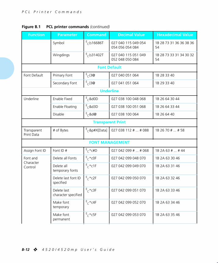
P C L P r i n t e r C o m m a n d s
B-12
❖
4 5 2 0 / 4 5 2 0 m p U s e r ’ s G u i d e
Symbol
EC
(s16686T 027 040 115 049 054 054 056 054 084
1B 28 73 31 36 36 38 36 54
Wingdings
EC
(s31402T 027 040 115 051 049 052 048 050 084
1B 28 73 33 31 34 30 32 54
Font Default
Font Default Primary Font
EC
(3@ 027 040 051 064 1B 28 33 40
Secondary Font
EC
)3@ 027 041 051 064 1B 29 33 40
Underline
Underline Enable Fixed
EC
&d0D 027 038 100 048 068 1B 26 64 30 44
Enable Floating
EC
&d3D 027 038 100 051 068 1B 26 64 33 44
Disable
EC
&d@ 027 038 100 064 1B 26 64 40
Transparent Print
Transparent Print Data
# of Bytes
EC
&p#X[Data] 027 038 112 # ... # 088 1B 26 70 # ... # 58
FONT MANAGEMENT
Assign Font ID Font ID #
EC
*c#D 027 042 099 # ... # 068 1B 2A 63 # ... # 44
Font and Character Control
Delete all Fonts
EC
*c0F 027 042 099 048 070 1B 2A 63 30 46
Delete all temporary fonts
EC
*c1F 027 042 099 049 070 1B 2A 63 31 46
Delete last font ID specified
EC
*c2F 027 042 099 050 070 1B 2A 63 32 46
Delete last character specified
EC
*c3F 027 042 099 051 070 1B 2A 63 33 46
Make font temporary
EC
*c4F 027 042 099 052 070 1B 2A 63 34 46
Make font permanent
EC
*c5F 027 042 099 053 070 1B 2A 63 35 46
Figure B.1 PCL printer commands
(continued)
Function
Parameter
Command
Decimal Value
Hexadecimal Value
WUG-APPB Page 12 Black,Cyan Sunday, January 22, 1995 9:01 PM

P C L P r i n t e r C o m m a n d s
A p p e n d i x B : P r i n t e r C o m m a n d s ( E s c a p e S e q u e n c e s )
❖
B-13
Copy/Assign the currently invoked font as temporary
EC
*c6F 027 042 099 054 070 1B 2A 63 36 46
Soft Symbol Set Management / Creation
Set Symbol Set ID #
EC
*c#R 027 042 099 # ... # 082 1B 2A 63 # ... # 52
Define Symbol Set
# of Bytes
EC
(f#W[Data] 027 040 102 # ... # 087 1B 28 66 # ... # 57
Symbol Set Control
Delete all symbol sets
EC
*c0S 027 042 099 048 083 1B 2A 63 30 53
Delete all temporary symbol sets
EC
*c1S 027 042 099 049 083 1B 2A 63 31 53
Delete current soft symbol set (last ID #)
EC
*c2S 027 042 099 050 083 1B 2A 63 32 53
Make current soft symbol set temporary
EC
*c4S 027 042 099 052 083 1B 2A 63 34 53
Make current soft symbol set permanent
EC
*c5S 027 042 099 053 083 1B 2A 63 35 53
Soft Symbol Set Management / Creation
Select Font (with ID #)
ID # primary font
EC
(#X 027 040 # ... # 088 1B 28 # ... # 58
ID # secondary font
EC
)#X 027 041 # ... # 088 1B 29 # ... # 58
SOFT FONT CREATION
Font Descriptor (font header)
# of bytes
EC
)s#W[Data] 027 041 115 # ... # 087 1B 29 73 # ... # 57
Download character
# of bytes
EC
(s#W[Data] 027 040 115 # ... # 087 1B 28 73 # ... # 57
Character code Character code # (decimal)
EC
*c#E 027 042 099 # ... # 069 1B 2A 63 # ... # 45
Figure B.1 PCL printer commands
(continued)
Function
Parameter
Command
Decimal Value
Hexadecimal Value
WUG-APPB Page 13 Black,Cyan Sunday, January 22, 1995 9:01 PM

P C L P r i n t e r C o m m a n d s
B-14
❖
4 5 2 0 / 4 5 2 0 m p U s e r ’ s G u i d e
GRAPHICS
Raster Graphics
Raster Resolution
75 dots/inch
EC
*t75R 027 042 116 055 053 082
1B 2A 74 37 35 52
100 dots/inch
EC
*t100R 027 042 116 049 048 048 082
1B 2A 74 31 30 30 52
150 dots/inch
EC
*t150R 027 042 116 049 053 048 082
1B 2A 74 31 35 30 52
200 dots/inch
EC
*t200R 027 042 116 050 048 048 082
1B 2A 74 32 30 30 52
300 dots/inch
EC
*t300R 027 042 116 051 048 048 082
1B 2A 74 33 30 30 52
400 dots/inch
EC
*t400R 027 042 116 052 048 048 082
1B 2A 74 34 30 30 52
600 dots/inch
EC
*t600R 027 042 116 054 048 048 082
1B 2A 74 36 30 30 52
800 dots/inch
EC
*t800R 027 042 116 056 048 048 082
1B 2A 74 38 30 30 52
Raster Graphics Presentation
Follows orientation
EC
*r0F 027 042 114 048 070 1B 2A 72 30 46
Follows physical page
EC
*r3F 027 042 114 051 070 1B 2A 72 33 46
Start Raster Graphics
Left Raster Graphics Margin
EC
*r0A 027 042 114 048 065 1B 2A 72 30 41
Current Cursor
EC
*r1A 027 042 114 049 065 1B 2A 72 31 41
Raster Y Offset # of Raster Lines of vertical movement
EC
*b#Y 027 042 098 # ... # 089 1B 2A 62 # ... # 59
Set Raster Compression Mode (Method)
Unencoded
EC
*b0M 027 042 098 048 077 1B 2A 62 30 4D
Run-Length Encoded
EC
*b1M 027 042 098 049 077 1B 2A 62 31 4D
Figure B.1 PCL printer commands
(continued)
Function
Parameter
Command
Decimal Value
Hexadecimal Value
WUG-APPB Page 14 Black,Cyan Sunday, January 22, 1995 9:01 PM

P C L P r i n t e r C o m m a n d s
A p p e n d i x B : P r i n t e r C o m m a n d s ( E s c a p e S e q u e n c e s )
❖
B-15
Tagged Image File Format
EC
*b2M 027 042 098 050 077 1B 2A 62 32 4D
Delta Row
EC
*b3M 027 042 098 051 077 1B 2A 62 33 4D
Adaptive compression
EC
*b5M 027 042 098 053 077 1B 2A 62 35 4D
Transfer Raster Data by row
# of Bytes
EC
*b#W[Data]
027 042 098 # ... # 087 1B 2A 62 # ... # 57
End Raster Graphics
Old version
EC
*rB 027 042 114 066 1B 2A 72 42
preferred
EC
*rC 027 042 114 067 1B 2A 72 43
Raster Height # Raster Rows
EC
*r#T 027 042 114 # ... # 084 1B 2A 72 # ... # 54
Raster Width # Pixels of the Specified Resolution
EC
*r#S 027 042 114 # ... # 083 1B 2A 72 # ... # 53
THE PRINT MODEL
Imaging
Select Current Pattern
Solid Black (default)
EC
*v0T 027 042 118 048 084 1B 2A 76 30 54
Solid White
EC
*v1T 027 042 118 049 084 1B 2A 76 31 54
HP-defined Shading Pattern
EC
*v2T 027 042 118 050 084 1B 2A 76 32 54
HP-defined Cross-Hatched Pattern
EC
*v3T 027 042 118 051 084 1B 2A 76 33 54
User-defined pattern
EC
*v4T 027 042 118 052 084 1B 2A 76 34 54
Source Transparency Mode
Transparent
EC
*v0N 027 042 118 048 078 1B 2A 76 30 4E
Opaque
EC
*v1N 027 042 118 049 078 1B 2A 76 31 4E
Pattern Transparency Mode
Transparent
EC
*v0O 027 042 118 048 079 1B 2A 76 30 4F
Opaque
EC
*v1O 027 042 118 049 079 1B 2A 76 31 4F
Figure B.1 PCL printer commands
(continued)
Function
Parameter
Command
Decimal Value
Hexadecimal Value
WUG-APPB Page 15 Black,Cyan Sunday, January 22, 1995 9:01 PM

P C L P r i n t e r C o m m a n d s
B-16
❖
4 5 2 0 / 4 5 2 0 m p U s e r ’ s G u i d e
Rectangle Dimensions
Rectangle Width (Horizontal Size)
# of dots
EC
*c#A 027 042 099 # ... # 065 1B 2A 63 # ... # 41
# of decipoints
EC
*c#H 027 042 099 # ... # 072 1B 2A 63 # ... # 48
Rectangle Height(Vertical Size)
# of dots
EC
*c#B 027 042 099 # ... # 066 1B 2A 63 # ... # 42
# of decipoints
EC
*c#V 027 042 099 # ... # 086 1B 2A 63 # ... # 56
Fill Rectangular Area
Solid Black
EC
*c0P 027 042 099 048 080 1B 2A 63 30 50
Erase (solid white fill)
EC
*c1P 027 042 099 049 080 1B 2A 63 31 50
Shaded Fill
EC
*c2P 027 042 099 050 080 1B 2A 63 32 50
Cross-hatched Fill
EC
*c3P 027 042 099 051 080 1B 2A 63 33 50
User-Defined
EC
*c4P 027 042 099 052 080 1B 2A 63 34 50
Current Pattern
EC
*c5P 027 042 099 053 080 1B 2A 63 35 50
Pattern ID % of Shading or Type of Pattern or User Pattern ID
EC
*c#G 027 042 099 # ... # 071 1B 2A 63 # ... # 47
Shading 2% Gray
EC
*c2G 027 042 099 050 071 1B 2A 63 32 47
10% Gray
EC
*c10G 027 042 099 049 048 071
1B 2A 63 31 30 47
15% Gray
EC
*c15G 027 042 099 049 053 071
1B 2A 63 31 35 47
30% Gray
EC
*c30G 027 042 099 051 048 071
1B 2A 63 33 30 47
45% Gray
EC
*c45G 027 042 099 052 053 071
1B 2A 63 34 35 47
70% Gray
EC
*c70G 027 042 099 055 048 071
1B 2A 63 37 30 47
90% Gray
EC
*c90G 027 042 099 057 048 071
1B 2A 63 39 30 47
Figure B.1 PCL printer commands
(continued)
Function
Parameter
Command
Decimal Value
Hexadecimal Value
WUG-APPB Page 16 Black,Cyan Sunday, January 22, 1995 9:01 PM

P C L P r i n t e r C o m m a n d s
A p p e n d i x B : P r i n t e r C o m m a n d s ( E s c a p e S e q u e n c e s )
❖
B-17
100% Gray
EC
*c100G 027 042 099 049 048 048 071
1B 2A 63 31 30 30 47
Pattern 1 Horiz. Line
EC
*c1G 027 042 099 049 071 1B 2A 63 31 47
2 Vert. Lines
EC
*c2G 027 042 099 050 071 1B 2A 63 32 47
3 Diagonal Lines
EC
*c3G 027 042 099 051 071 1B 2A 63 33 47
4 Diagonal Lines
EC
*c4G 027 042 099 052 071 1B 2A 63 34 47
5 Square Grid
EC
*c5G 027 042 099 053 071 1B 2A 63 35 47
6 Diagonal Grid
EC
*c6G 027 042 099 054 071 1B 2A 63 36 47
USER-DEFINED PATTERN / MANAGEMENT CREATION
Define Pattern # of bytes
EC
*c#W[Data]
027 042 099 # ... # 087 1B 2A 63 # ... # 57
User-Defined Pattern Control
Delete all patterns
EC
*c0Q 027 042 099 048 081 1B 2A 63 30 51
Delete all temporary patterns
EC
*c1Q 027 042 099 049 081 1B 2A 63 31 51
Delete current pattern
EC
*c2Q 027 042 099 050 081 1B 2A 63 32 51
Make pattern temporary
EC
*c4Q 027 042 099 052 081 1B 2A 63 34 51
Make pattern permanent
EC
*c5Q 027 042 099 053 081 1B 2A 63 35 51
Set Pattern Reference
Rotate with orientation
EC
*p0R 027 042 112 048 082 1B 2A 70 30 52
Point Follow physical page
EC
*p1R 027 042 112 049 082 1B 2A 70 31 52
MACROS
Macro ID Macro ID #
EC
&f#Y 027 038 102 # ... # 089 1B 26 66 # ... # 59
Figure B.1 PCL printer commands
(continued)
Function
Parameter
Command
Decimal Value
Hexadecimal Value
WUG-APPB Page 17 Black,Cyan Sunday, January 22, 1995 9:01 PM

P C L P r i n t e r C o m m a n d s
B-18
❖
4 5 2 0 / 4 5 2 0 m p U s e r ’ s G u i d e
Macro Control Start Macro Def.
EC
&f0X 027 038 102 048 088 1B 26 66 30 58
Stop Macro Def.
EC
&f1X 027 038 102 049 088 1B 26 66 31 58
Execute Macro
EC
&f2X 027 038 102 050 088 1B 26 66 32 58
Call Macro
EC
&f3X 027 038 102 051 088 1B 26 66 33 58
Enable Overlay
EC
&f4X 027 038 102 052 088 1B 26 66 34 58
Disable Overlay
EC
&f5X 027 038 102 053 088 1B 26 66 35 58
Delete Macros
EC
&f6X 027 038 102 054 088 1B 26 66 36 58
Delete All Temp. Macros
EC
&f7X 027 038 102 055 088 1B 26 66 37 58
Delete Macro ID
EC
&f8X 027 038 102 056 088 1B 26 66 38 58
Make Temporary
EC
&f9X 027 038 102 057 088 1B 26 66 39 58
Make Permanent
EC
&f10X 027 038 102 049 048 088
1B 26 66 31 30 58
STATUS READBACK
Set Status Readback Location Type
Invalid Location
EC
*s0T 027 042 115 048 084 1B 2A 73 30 54
Currently Selected
EC
*s1T 027 042 115 049 084 1B 2A 73 31 54
All Locations
EC
*s2T 027 042 115 050 084 1B 2A 73 32 54
Internal
EC
*s3T 027 042 115 051 084 1B 2A 73 33 54
Downloaded
EC
*s4T 027 042 115 052 084 1B 2A 73 34 54
Cartridge
EC
*s5T 027 042 115 053 084 1B 2A 73 35 54
User-Installed ROM (SIMMs)
EC
*s7T 027 042 115 055 084 1B 2A 73 37 54
Figure B.1 PCL printer commands
(continued)
Function
Parameter
Command
Decimal Value
Hexadecimal Value
WUG-APPB Page 18 Black,Cyan Sunday, January 22, 1995 9:01 PM

P C L P r i n t e r C o m m a n d s
A p p e n d i x B : P r i n t e r C o m m a n d s ( E s c a p e S e q u e n c e s )
❖
B-19
Set Status Readback Location Unit
All entities of the Location Type
EC
*s0U 027 042 115 048 085 1B 2A 73 30 55
Entity 1 or Temporary
EC
*s1U 027 042 115 049 085 1B 2A 73 31 55
Entity 2 or Permanent
EC
*s2U 027 042 115 050 085 1B 2A 73 32 55
Entity 3
EC
*s3U 027 042 115 051 085 1B 2A 73 33 55
Entity 4
EC
*s4U 027 042 115 052 085 1B 2A 73 34 55
Inquire Status Readback Entity
Font
EC
*s0I 027 042 115 048 073 1B 2A 73 30 49
Macro
EC
*s1I 027 042 115 049 073 1B 2A 73 31 49
User-defined Pattern
EC
*s2I 027 042 115 050 073 1B 2A 73 32 49
Symbol Set
EC
*s3I 027 042 115 051 073 1B 2A 73 33 49
Font Extended
EC
*s4I 027 042 115 052 073 1B 2A 73 34 49
Flush All Pages Flush All complete pages
EC
&r0F 027 038 114 048 070 1B 26 72 30 46
Flush All Page Data
EC
&r1F 027 038 114 049 070 1B 26 72 31 46
Free Memory Space
—
EC
*s1M 027 042 115 049 077 1B 2A 73 31 4D
Echo # = Echo value (-32767 to 32767)
EC
*s#X 027 042 115 # ... # 088 1B 2A 73 # ... # 58
Figure B.1 PCL printer commands
(continued)
Function
Parameter
Command
Decimal Value
Hexadecimal Value
WUG-APPB Page 19 Black,Cyan Sunday, January 22, 1995 9:01 PM

P C L P r i n t e r C o m m a n d s
B-20
❖
4 5 2 0 / 4 5 2 0 m p U s e r ’ s G u i d e
PROGRAMMING HINTS
End-Of-Line Wrap
Enabled
EC
&s0C 027 038 115 048 067 1B 26 73 30 43
Disabled
EC
&s1C 027 038 115 049 067 1B 26 73 31 43
Display Functions
ON
EC
Y 027 089 1B 59
OFF
EC
Z 027 090 1B 5A
PCL VECTOR GRAPHICS SWITCHING/SET-UP PICTURE FRAME
Enter PCL Mode Use previous PCL cursor position
EC
%0A 027 037 048 065 1B 25 30 41
Use current HP-GL/2 pen position for cursor position
EC
%1A 027 037 049 065 1B 25 31 41
Enter HP-GL/2 Mode
Use Previous HP-GL/2 pen position
EC
%0B 027 037 048 066 1B 25 30 42
Use current PCL cursor position
EC
%1B 027 037 049 066 1B 25 31 42
HP-GL/2 Plot Horizontal Size
Horizontal size in inches
EC
*c#K 027 042 099 # ... # 075 1B 2A 63 # ... # 4B
HP-GL/2 Plot Vertical Size
Vertical size in inches
EC
*c#L 027 042 099 # ... # 076 1B 2A 63 # ... # 4C
Set Picture Frame Anchor Point
Set anchor point to cursor position
EC
*c0T 027 042 099 048 084 1B 2A 63 30 54
Picture Frame Horizontal Size
Decipoints
EC
*c#X 027 042 099 # ... # 088 1B 2A 63 # ... # 58
Picture Frame Vertical Size
Decipoints
EC
*c#Y 027 042 099 # ... # 089 1B 2A 63 # ... # 59
Figure B.1 PCL printer commands
(continued)
Function
Parameter
Command
Decimal Value
Hexadecimal Value
WUG-APPB Page 20 Black,Cyan Sunday, January 22, 1995 9:01 PM

H P - G L / 2 C o n t e x t P r i n t e r C o m m a n d s
A p p e n d i x B : P r i n t e r C o m m a n d s ( E s c a p e S e q u e n c e s )
❖
B-21
In Figure B.2, parameters in brackets [] are optional.
Figure B.2 HP-GL/2 Context Printer Commands
Command
Mnemonic
Parameters
DUAL CONTEXT EXTENSIONS
Enter PCL Mode Esc%#A 0 - Retain previous PCL cursor position1 - Use current HP-GL/2 pen position
Reset EscE None
Primary Font F1 Font_ID
Secondary Font FN Font_ID
Scalable Or Bitmapped Fonts SB 0 - Scalable fonts only1 - Bitmapped fonts allowed
PALETTE EXTENSIONS
Transparency Mode TR 0 - Off (opaque)1 - On (transparent)
Screened Vectors SV [screen_type[,shading[,index]]]
VECTOR GROUP
Arc Absolute AA x_center, y_center, sweep_angle [,chord_angle];
Arc Relative AR x_increment, y_increment, sweep-angle [,chord_angle];
Absolute Arc Three Point AT x_inter, y_inter, x_end, y_end [,chord_angle];
Bezier Absolute BZ x1_control_pt, y1_control_ptx2_control_pt, y2_control_ptx3_control_pt, y3_control_pt . . .[x1_control_pt, y1_control_ptx2_control_pt, y2_control_ptx3_control_pt, y3_control_pt];
HP-GL/2Context
PrinterCommands
WUG-APPB Page 21 Black,Cyan Sunday, January 22, 1995 9:01 PM

H P - G L / 2 C o n t e x t P r i n t e r C o m m a n d s
B-22
❖
4 5 2 0 / 4 5 2 0 m p U s e r ’ s G u i d e
Bezier Relative BR x1_control_pt_increments,y1_control_pt_increments,x2_control_pt_increments,y2_control_pt_incrementsx3_control_pt_increments,y3_control_pt_increments . . .[x1_control_pt_increments,y1_control_pt_increments,x2_control_pt_increments,y2_control_pt_increments,x3_control_pt_increments, y3_control_pt_increments];
Plot Absolute PA [x,y . . . [,x,y]];
Plot Relative PR [x,y . . . [,x,y]];
Pen Down PD [x,y . . . [,x,y]];
Pen Up PU [x,y . . . [,x,y]];
Relative Arc Three Point RT x_incr_inter, y_incr_inter, x_incr_end, y_incr_end [,chord_angle];
Polyline Encoded PE [flag[val]|coord_pair . . . [flag[val]|coord_pair]];
POLYGON GROUP
Circle CI radius [,chord_angle];
Fill Rectangle Absolute RA x_coordinate, y_coordinate;
Fill Rectangle Relative RR x_increment, y_increment;
Edge Rectangle Absolute EA x_coordinate, y_coordinate;
Edge Rectangle Relative ER x_increment, y_increment;
Fill Wedge WG radius, start_angle, sweep_angle [,chord_angle];
Edge Wedge EW radius, start_angle, sweep_angle [,chord_angle];
Polygon Mode PM polygon_definition;
Fill Polygon FP 0 - Odd/Even1 - non-zero winding
Edge Polygon EP None
Figure B.2 HP-GL/2 Context Printer Commands
(continued)
Command
Mnemonic
Parameters
WUG-APPB Page 22 Black,Cyan Sunday, January 22, 1995 9:01 PM

H P - G L / 2 C o n t e x t P r i n t e r C o m m a n d s
A p p e n d i x B : P r i n t e r C o m m a n d s ( E s c a p e S e q u e n c e s )
❖
B-23
CHARACTER GROUP
Select Standard Font SS None
Select Alternate Font SA None
Absolute Direction DI [run, rise];
Relative Direction DR [run, rise];
Absolute Character Size SI [width, height];
Relative Character Size SR [width, height];
Character Slant SL [tangent_of_angle];
Extra Space ES [width [,height]]
Standard Font Definition SD [kind, value . . . [,kind, value]];
Alternate Font Definition AD [kind, value . . . [,kind, value]];
Character Fill Mode CF [fill_mode [,edge_pen]];
Label Origin LO [position];
Label LB [char . . . [char]]1bterm
Define Label Terminator DT [1bterm [,mode]];
Character Plot CP [spaces, lines];
Transparent Data TD [mode];
Define Variable Text Path DV [path [,line]];
Figure B.2 HP-GL/2 Context Printer Commands
(continued)
Command
Mnemonic
Parameters
WUG-APPB Page 23 Black,Cyan Sunday, January 22, 1995 9:01 PM

H P - G L / 2 C o n t e x t P r i n t e r C o m m a n d s
B-24
❖
4 5 2 0 / 4 5 2 0 m p U s e r ’ s G u i d e
LINE AND FILL ATTRIBUTES GROUP
Line Type LT [line_type [,pattern_length [,mode]]];
Line Attributes LA [kind, value . . . [,kind, value]];
Pen Width PW [width [,pen]];
Pen Width Unit Selection WU [type];
Select Pen SP [pen];
(required, 1 for black (recommended) or 0 for white)
Symbol Mode SM [char];
Fill Type FT [fill_type [,option1 [,option2]]];
Anchor Corner AC [x_coordinate, y_coordinate];
Raster Fill Definition RF [index [,width, height, pen_nbr . . . pen_nbr]];
(width and height must be less than 255)
User Defined Line Type UL [index [,gap1 . . . gapn]];
CONFIGURATION AND STATUS GROUP
Scale SC [x1, x2, y1, y2 [,type [,left, bottom]]];or[x1,xfactor,y1,yfactor,2];
Input Window IW [xLL,yLL,xUR,yUR];
Input P1 and P2 IP [p1x, p1y [,p2x, p2y]];
Input Relative P1 and P2 IR [p1x, p1y [,p2x, p2y]];
Default Values DF None
Initialize IN [n];
Rotate Coordinate System RO [angle];
Figure B.2 HP-GL/2 Context Printer Commands
(continued)
Command
Mnemonic
Parameters
WUG-APPB Page 24 Black,Cyan Sunday, January 22, 1995 9:01 PM

C o n t r o l C o d e s
A p p e n d i x B : P r i n t e r C o m m a n d s ( E s c a p e S e q u e n c e s )
❖
B-25
Figure B.3 Control Codes
Function
Symbol
Decimal Value
Description
Backspace B
S
8 Move one column left unless at left margin, in which case no action is taken.
Horizontal Tab H
T
9 Move to next horizontal tab stop. The tab stops are at the left margin, and every eight columns to the right of the left margin.
Line Feed L
F
10 Move to next print line while maintaining current column position.
Form Feed F
F
12 Move to the first line at top of the next page while maintaining current column position.
Carriage Return C
R
13 Move to left margin on the current print line.
Shift Out S
O
14 Select characters that follow from the current secondary font until receipt of a Shift In.
Shift In S
I
15 Select characters that follow from the current primary font until receipt of a Shift Out.
Escape E
C
27 Indicates the beginning of a special control sequence (escape sequence).
Space S
P
32 Move one column to the right unless already at the right margin, in which case no action is taken.
Control Codes
WUG-APPB Page 25 Black,Cyan Sunday, January 22, 1995 9:01 PM

B-26
❖
4 5 2 0 / 4 5 2 0 m p U s e r ’ s G u i d e
WUG-APPB Page 26 Black Sunday, January 22, 1995 9:01 PM

Appendix C
A p p e n d i x C : I / O P o r t P o l l i n g
❖
C-1
I/O Port Polling
Appendix C
WUG-APPC Page 1 Black,Cyan Sunday, January 22, 1995 9:07 PM

C-2
❖
4 5 2 0 / 4 5 2 0 m p U s e r ’ s G u i d e
The 4520/4520mp printers provide a parallel port, serial port, and three additional network interface port options,
all of which may be active at the same time
.
Automatic switching
among all active I/O (input/output) ports is supported.
Port Polling Without a Hard Disk Installed
To coordinate automatic switching among the ports, the printer monitors the parallel, serial, and network interface
ports for incoming data. When a print job is detected on one port, the printer sends a busy signal to the other ports and queues the print job into memory for processing. This is called
port polling
. Note that while all ports may be simultaneously active, only one port at a time is able to receive a print job.
When print jobs are pending on all five ports (parallel, serial,
Ethernet, LocalTalk, and Token Ring), the port polling sequence is:
1 Parallel
2 Serial
3 Ethernet
4 Token Ring
5 Back to Parallel
LocalTalk
is not a part of this sequence. When a print job is detected on the LocalTalk port, the print job is put in the queue immediately after any current job finishes.
Note
WUG-APPC Page 2 Black,Cyan Sunday, January 22, 1995 9:07 PM

A p p e n d i x C : I / O P o r t P o l l i n g
❖
C-3
Except for those on the LocalTalk interface,
print jobs are processed in the sequence in which they are received by the printer
. As soon as one print job has finished, the printer continues polling until it finds another port that has received data.
If a print job is incomplete, the printer waits until the port is inactive for the
Port Timeout
period. After that, the printer
ends the incomplete job and continues polling the ports when either:
•
Auto Job End
is
On
or
• Another print job is received on a port
Therefore, the printer does not excessively service one particular port.
You may set the
Port Timeout
period and
Auto Job End
on the Control Panel or with the RUI. For additional information on
Port Timeout
or
Auto Job End
, either see
Chapter 3: Using the Control Panel
, or refer to the
Document Services for
Printing Guide
.
Port Polling With a Hard Disk Installed
When a hard disk is installed, the printer can spool print jobs from the parallel and serial ports. The print jobs are spooled, without any processing, onto the hard disk. Jobs are then processed in the order in which they were received.
WUG-APPC Page 3 Black,Cyan Sunday, January 22, 1995 9:07 PM

C-4
❖
4 5 2 0 / 4 5 2 0 m p U s e r ’ s G u i d e
WUG-APPC Page 4 Black Sunday, January 22, 1995 9:07 PM

Appendix D
A p p e n d i x D : O r d e r i n g I n f o r m a t i o n
❖
D-1
Ordering Information
Appendix D
Printer Options
....................................................................
D-2
Additional Order Items
.......................................................
D-8
WUG-APPD Page 1 Black,Red,Cyan Sunday, January 22, 1995 9:09 PM
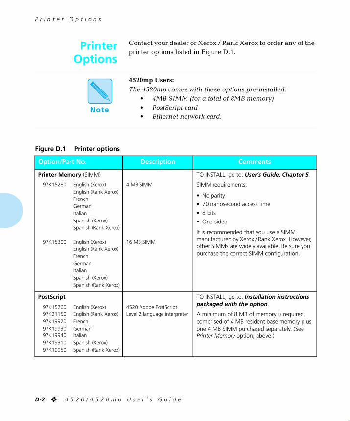
P r i n t e r O p t i o n s
D-2
❖
4 5 2 0 / 4 5 2 0 m p U s e r ’ s G u i d e
Contact your dealer or Xerox / Rank Xerox to order any of the printer options
listed in Figure D.1.
4520mp Users:
The 4520mp comes with these options pre-installed: • 4MB SIMM (for a total of 8MB memory)• PostScript card
• Ethernet network card.
Figure D.1 Printer options
Option/Part No.
Description
Comments
Printer Memory
(SIMM)
97K15280 English (Xerox)English (Rank Xerox)FrenchGermanItalianSpanish (Xerox)Spanish (Rank Xerox)
97K15300 English (Xerox)English (Rank Xerox)FrenchGermanItalianSpanish (Xerox)Spanish (Rank Xerox)
4 MB SIMM
16 MB SIMM
TO INSTALL, go to:
User’s Guide, Chapter 5
.
SIMM requirements:
• No parity
• 70 nanosecond access time
• 8 bits
• One-sided
It is recommended that you use a SIMM manufactured by Xerox / Rank Xerox. However, other SIMMs are widely available. Be sure you purchase the correct SIMM configuration.
PostScript
97K15260 English (Xerox)97K21150 English (Rank Xerox)97K19920 French97K19930 German97K19940 Italian97K19310 Spanish (Xerox)97K19950 Spanish (Rank Xerox)
4520 Adobe PostScript Level 2 language interpreter
TO INSTALL, go to:
Installation instructions packaged with the option
.
A minimum of 8 MB of memory is required, comprised of 4 MB resident base memory plus one 4 MB SIMM purchased separately. (See
Printer Memory
option, above.)
PrinterOptions
Note
WUG-APPD Page 2 Black,Red,Cyan Sunday, January 22, 1995 9:09 PM

P r i n t e r O p t i o n s
A p p e n d i x D : O r d e r i n g I n f o r m a t i o n
❖
D-3
Font Cards
Contact Xerox / Rank Xerox
English (Xerox)English (Rank Xerox)FrenchGermanItalianSpanish (Xerox)Spanish (Rank Xerox)
TO INSTALL, go to:
User’s Guide, Chapter 5
.
For PCL5e only.
Hard Disk
97K15370 English (Xerox)97K19850 English (Rank Xerox)97K19860 French97K19870 German97K19880 Italian97K19320 Spanish (Xerox)97K19890 Spanish (Rank Xerox)
125 MB Hard Disk
TO INSTALL, go to:
Installation instructions packaged with the option
.
Figure D.1 Printer options
(continued)
Option/Part No.
Description
Comments
WUG-APPD Page 3 Black,Red,Cyan Sunday, January 22, 1995 9:09 PM

P r i n t e r O p t i o n s
D-4
❖
4 5 2 0 / 4 5 2 0 m p U s e r ’ s G u i d e
Network Interfaces
97K15330 English (Xerox)97K19610 English (Rank Xerox)97K19620 French97K19630 German97K19640 Italian97K19270 Spanish (Xerox)97K19650 Spanish (Rank Xerox)
97K15320 English (Xerox)97K19550 English (Rank Xerox)97K19560 French97K19570 German97K19580 Italian97K19260 Spanish (Xerox)97K19590 Spanish (Rank Xerox)
97K15340 English (Xerox)97K19670 English (Rank Xerox)97K19680 French97K19690 German97K19700 Italian97K19280 Spanish (Xerox)97K19710 Spanish (Rank Xerox)
Ethernet card
(with BNC and RJ-45 connectors)
LocalTalk card
(with a DIN-8 connector)
Token Ring card
(with RJ-45 and female DE-9 connectors)
TO INSTALL, go to:
Installation instructions packaged with the option
.
The
Ethernet
card supports the following protocols:• Novell NetWare• TCP/IP• EtherTalk• DEC LAT• LAN Manager
The
Token
Ring
card supports the following protocols:• Novell NetWare• LAN Manager
Novell
systems require Print Server v1.2 and above, in the form of:• PSERVER.VAP for v2.x NetWare file
servers• PSERVER.NLM for v3.x NetWare
file servers• PSERVER.EXE for a stand-alone
PC-based print server
UNIX TCP/IP
systems require:• Support for lpd or rprint
(Xerox-supplied)• Clients must support TCP/IP,
TELNET, and UDP• Optional load hosts require TFTP or
RARP protocols
EtherTalk
and
TokenTalk
systems require AppleTalk Phase 2.
DEC
LAT
systems (Ethernet only) require that clients support the LAT protocol under the VAX/VMS or ULTRIX-32 operating systems.
LAN Manager
systems require:• OS/2 version 1.30 or above• Microsoft’s LAN Manager version
2.1 and above• TCP/IP on the LAN Manager server
Figure D.1 Printer options
(continued)
Option/Part No.
Description
Comments
WUG-APPD Page 4 Black,Red,Cyan Sunday, January 22, 1995 9:09 PM

P r i n t e r O p t i o n s
A p p e n d i x D : O r d e r i n g I n f o r m a t i o n
❖
D-5
PAPER HANDLING OPTIONS
(For paper sizes, refer to the
User’s Guide, Chapter 2: Handling Paper
.)
Paper Trays
TO INSTALL, go to:
User’s Guide, Chapter 2
.
109R00020 English (Xerox)English (Rank Xerox)FrenchGermanItalianSpanish (Xerox)Spanish (Rank Xerox)
Universal
Adjustable to:• A4• 8.5 x 11 (Letter)• 8.5 x 13 (Folio)• 8.5 x 14 (Legal)• 11 x 17 (Ledger)• A3
109R00017 English (Xerox)English (Rank Xerox)FrenchGermanItalianSpanish (Xerox)Spanish (Rank Xerox)
Fixed A4 Not adjustable
109R00023 English (Xerox)English (Rank Xerox)FrenchGermanItalianSpanish (Xerox)Spanish (Rank Xerox)
Fixed 8.5 x 11 (Letter) Not adjustable
109R00018 English (Xerox)English (Rank Xerox)FrenchGermanItalianSpanish (Xerox)Spanish (Rank Xerox)
Fixed A5 Not adjustable
109R00022 English (Xerox)English (Rank Xerox)FrenchGermanItalianSpanish (Xerox)Spanish (Rank Xerox)
Fixed 8.5 x 14 (Legal) Not adjustable
Figure D.1 Printer options
(continued)
Option/Part No.
Description
Comments
WUG-APPD Page 5 Black,Red,Cyan Sunday, January 22, 1995 9:09 PM

P r i n t e r O p t i o n s
D-6
❖
4 5 2 0 / 4 5 2 0 m p U s e r ’ s G u i d e
109R00021 English (Xerox)English (Rank Xerox)FrenchGermanItalianSpanish (Xerox)Spanish (Rank Xerox)
Fixed 11 x 17 (Ledger) Not adjustable
109R00016 English (Xerox)English (Rank Xerox)FrenchGermanItalianSpanish (Xerox)Spanish (Rank Xerox)
Fixed A3 Not adjustable
High-Capacity Feeder (HCF)
TO INSTALL, go to:
Installation instructions packaged with the option
.
97K15750 English (Xerox)97K20000 English (Rank Xerox)97K20010 French97K20020 German97K20030 Italian97K19440 Spanish (Xerox)97K20040 Spanish (Rank Xerox)
1500-sheet A4 feeder
The HCF attaches to the SBF slot.
97K15740 English (Xerox)97K19430 Spanish (Xerox)
1500-sheet 8.5 x 11 (Letter) feeder
High-Capacity Envelope Feeder (HCEF)
TO INSTALL, go to:
Installation instructions packaged with the option
.
97K15760 English (Xerox)97K19450 Spanish (Xerox)
250 COM-10 envelope feeder
The HCEF attaches to the SBF slot.
97K15770 English (Xerox)97K20060 English (Rank Xerox)97K20070 French97K20080 German97K20090 Italian97K19460 Spanish (Xerox)97K20100 Spanish (Rank Xerox)
250 DL envelope feeder
Figure D.1 Printer options
(continued)
Option/Part No.
Description
Comments
WUG-APPD Page 6 Black,Red,Cyan Sunday, January 22, 1995 9:09 PM

P r i n t e r O p t i o n s
A p p e n d i x D : O r d e r i n g I n f o r m a t i o n
❖
D-7
Multi-sheet Bypass Feeder (MBF)
109R00034 English (Xerox)97K20120 English (Rank Xerox)97K20130 French97K20140 German97K20150 Italian97K19350 Spanish (Xerox)97K20160 Spanish (Rank Xerox)
Multiple sheet, envelope, or transparency feeder
TO INSTALL, go to:
Installation instructions packaged with the option
.
The MBF attaches to the SBF slot.
Adjustable to:• A4• 8.5 x 11 (Letter)• 8.5 x 13 (Folio)• 8.5 x 14 (Legal)• Executive• A5• B5 (ISO)• DL• COM10• C5
Figure D.1 Printer options
(continued)
Option/Part No.
Description
Comments
WUG-APPD Page 7 Black,Red,Cyan Sunday, January 22, 1995 9:09 PM

A d d i t i o n a l O r d e r I t e m s
D-8
❖
4 5 2 0 / 4 5 2 0 m p U s e r ’ s G u i d e
Figure D.2 shows additional items for the 4520/4520mp you may order from your dealer or Xerox / Rank Xerox.
Figure D.2 Additional order items
Type/Part No.
Description
Comments
EP Cartridge
113R2 English (Xerox)English (Rank Xerox)FrenchGermanItalianSpanish (Xerox)Spanish (Rank Xerox)
See
Chapter 6: Maintaining the Printer
for installation instructions.
Cables
See
Appendix A: Printer and Cable Specifications
for cable information.
AdditionalOrder Items
WUG-APPD Page 8 Black,Red,Cyan Sunday, January 22, 1995 9:09 PM
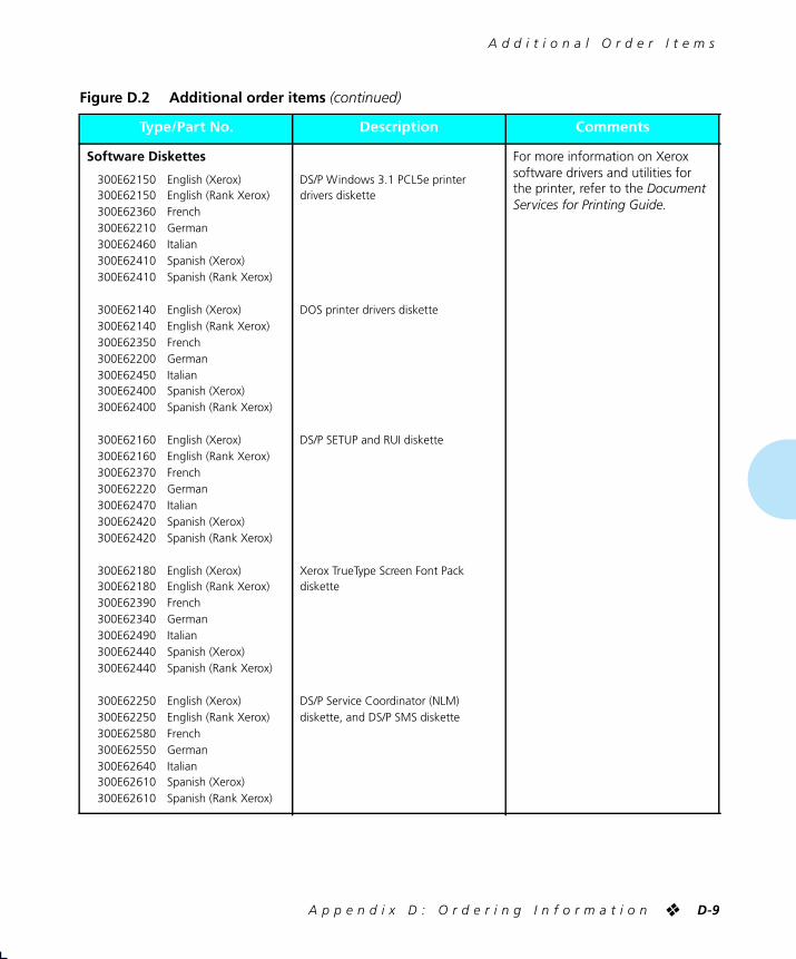
A d d i t i o n a l O r d e r I t e m s
A p p e n d i x D : O r d e r i n g I n f o r m a t i o n
❖
D-9
Software Diskettes
300E62150 English (Xerox)300E62150 English (Rank Xerox)300E62360 French300E62210 German300E62460 Italian300E62410 Spanish (Xerox)300E62410 Spanish (Rank Xerox)
300E62140 English (Xerox)300E62140 English (Rank Xerox)300E62350 French300E62200 German300E62450 Italian300E62400 Spanish (Xerox)300E62400 Spanish (Rank Xerox)
300E62160 English (Xerox)300E62160 English (Rank Xerox)300E62370 French300E62220 German300E62470 Italian300E62420 Spanish (Xerox)300E62420 Spanish (Rank Xerox)
300E62180 English (Xerox)300E62180 English (Rank Xerox)300E62390 French300E62340 German300E62490 Italian300E62440 Spanish (Xerox)300E62440 Spanish (Rank Xerox)
300E62250 English (Xerox)300E62250 English (Rank Xerox)300E62580 French300E62550 German300E62640 Italian300E62610 Spanish (Xerox)300E62610 Spanish (Rank Xerox)
DS/P Windows 3.1 PCL5e printer drivers diskette
DOS printer drivers diskette
DS/P SETUP and RUI diskette
Xerox TrueType Screen Font Pack diskette
DS/P Service Coordinator (NLM) diskette, and DS/P SMS diskette
For more information on Xerox software drivers and utilities for the printer, refer to the
Document Services for Printing Guide
.
Figure D.2 Additional order items
(continued)
Type/Part No.
Description
Comments
WUG-APPD Page 9 Black,Red,Cyan Sunday, January 22, 1995 9:09 PM

A d d i t i o n a l O r d e r I t e m s
D-10
❖
4 5 2 0 / 4 5 2 0 m p U s e r ’ s G u i d e
Software Diskettes
(continued)
300K39990 English (Xerox)300K39990 English (Rank Xerox)300K40110 French300K40000 German300K40070 Italian300K40060 Spanish (Xerox)300K40060 Spanish (Rank Xerox)
300K30151 English (Xerox)300K30151 English (Rank Xerox)300K40100 French300K40090 German300K40120 Italian300K40110 Spanish (Xerox)300K40110 Spanish (Rank Xerox)
300E62240 English (Xerox)300E62240 English (Rank Xerox)300E62710 French300E62700 German300E62730 Italian300E62720 Spanish (Xerox)300E62720 Spanish (Rank Xerox)
300E62260 English (Xerox)300E62260 English (Rank Xerox)
300E62270 English (Xerox)300E62270 English (Rank Xerox)
300E64510 English (Xerox)300E64510 English (Rank Xerox)
Disk Kit, containing all of the above
Macintosh PostScript printer driver diskette
Windows PostScript printer drivers diskette
XNIC software DOS distribution diskette
XNIC software UNIX distribution diskette
XNIC software Lan Manager distribution diskette
For more information on Xerox software drivers and utilities for the printer, refer to the
Document Services for Printing Guide
.
Figure D.2 Additional order items
(continued)
Type/Part No.
Description
Comments
WUG-APPD Page 10 Black,Red,Cyan Sunday, January 22, 1995 9:09 PM

A d d i t i o n a l O r d e r I t e m s
A p p e n d i x D : O r d e r i n g I n f o r m a t i o n
❖
D-11
User Documentation
720P53360 English (Xerox)720P53360 English (Rank Xerox)720P55360 French720P54360 German720P57360 Italian720P56360 Spanish (Xerox)720P56360 Spanish (Rank Xerox)
720P53100 English (Xerox)721P53100 English (Rank Xerox)720P55100 French720P54100 German720P57100 Italian720P56100 Spanish (Xerox)721P56100 Spanish (Rank Xerox)
720P53110 English (Xerox)721P53110 English (Rank Xerox)720P55110 French720P54110 German720P57110 Italian720P56110 Spanish (Xerox)721P56110 Spanish (Rank Xerox)
720P53040 English (Xerox)721P53040 English (Rank Xerox)720P55040 French720P54040 German720P57040 Italian720P56040 Spanish (Xerox)721P56040 Spanish (Rank Xerox)
720S53150 English (Xerox)721S53150 English (Rank Xerox)720S55150 French720S54150 German720S57150 Italian720S56150 Spanish (Xerox)721S56150 Spanish (Rank Xerox)
Quick Reference
Setting Up Guide
User’s Guide
Document Services for Printing Guide
Document kit, containing the four preceding documents
Figure D.2 Additional order items
(continued)
Type/Part No.
Description
Comments
WUG-APPD Page 11 Black,Red,Cyan Sunday, January 22, 1995 9:09 PM

A d d i t i o n a l O r d e r I t e m s
D-12
❖
4 5 2 0 / 4 5 2 0 m p U s e r ’ s G u i d e
User Documentation
(continued)
720P53320 English (Xerox)721P53320 English (Rank Xerox)720P55320 French720P54320 German720P57320 Italian720P56320 Spanish (Xerox)721P56320 Spanish (Rank Xerox)
720P53050 English (Xerox)721P53050 English (Rank Xerox)720P55050 French720P54050 German720P57050 Italian720P56050 Spanish (Xerox)721P56050 Spanish (Rank Xerox)
720P53060 English (Xerox)721P53060 English (Rank Xerox)720P55060 French720P54060 German720P57060 Italian720P56060 Spanish (Xerox)721P56060 Spanish (Rank Xerox)
Multi-sheet Bypass Feeder (MBF) Installation Instructions
High-Capacity Feeder (HCF) Installation Instructions
High-Capacity Envelope Feeder (HCEF) Installation Instructions
Figure D.2 Additional order items
(continued)
Type/Part No.
Description
Comments
WUG-APPD Page 12 Black,Red,Cyan Sunday, January 22, 1995 9:09 PM

A d d i t i o n a l O r d e r I t e m s
A p p e n d i x D : O r d e r i n g I n f o r m a t i o n
❖
D-13
User Documentation
(continued)
720P53180 English (Xerox)721P53180 English (Rank Xerox)720P55180 French720P54180 German720P57180 Italian720P56180 Spanish (Xerox)721P56180 Spanish (Rank Xerox)
720P53200 English (Xerox)721P53200 English (Rank Xerox)720P55200 French720P54200 German720P57200 Italian720P56200 Spanish (Xerox)721P56200 Spanish (Rank Xerox)
720P53190 English (Xerox)721P53190 English (Rank Xerox)720P55190 French720P54190 German720P57190 Italian720P56190 Spanish (Xerox)721P56190 Spanish (Rank Xerox)
720P53210 English (Xerox)721P53210 English (Rank Xerox)720P55210 French720P54210 German720P57210 Italian720P56210 Spanish (Xerox)721P56210 Spanish (Rank Xerox)
720P53170 English (Xerox)721P53170 English (Rank Xerox)720P55170 French720P54170 German720P57170 Italian720P56170 Spanish (Xerox)721P56170 Spanish (Rank Xerox)
Networking: Ethernet (XNIC-E’NET) Installation and Configuration Guide
Networking: LocalTalk (XNIC-L’TALK) Installation and Configuration Guide
Networking: Token Ring (XNIC-T’RING) Installation and Configuration Guide
PostScript Installation Instructions
Hard Disk Installation Instructions
Figure D.2 Additional order items
(continued)
Type/Part No.
Description
Comments
WUG-APPD Page 13 Black,Red,Cyan Sunday, January 22, 1995 9:09 PM

D-14
❖
4 5 2 0 / 4 5 2 0 m p U s e r ’ s G u i d e
WUG-APPD Page 14 Black,Red Sunday, January 22, 1995 9:09 PM

Appendix E
A p p e n d i x E : E n v i r o n m e n t a l S p e c i f i c a t i o n s
❖
E-1
Environmental Specifications
Appendix E
WUG-APPE Page 1 Black,Cyan Sunday, January 22, 1995 9:13 PM

E-2
❖
4 5 2 0 / 4 5 2 0 m p U s e r ’ s G u i d e
Xerox Corporation is committed to an international program to safeguard our environment by diverting certain products and materials from the solid waste stream. We do this by reusing serviceable components and remanufacturing selected products.
To support this effort we have made it easy for you to return selected printer equipment and empty print cartridges to Xerox. We recondition the print cartridges and refill them with Xerox toner and developer. All products we manufacture meet our stringent performance standards and are backed by the same Total Satisfaction Guarantee we offer with our newly manufactured products.
The world-wide effort to remanufacture printer equipment and recondition and reuse print cartridges benefits the environment and conserves our natural resources by reducing waste going into our landfills. Besides, it makes good business sense for Xerox and Xerox customers. Please join us in this effort.
On Standby (ROS Pause): 40 dB(A)
Under Operation:Continuous Sound: 53 dB(A)Impulse Sound: 65 dB(A)
The XeroxCommitment toEnvironmental
Quality
AcousticNoise Figures
WUG-APPE Page 2 Black,Cyan Sunday, January 22, 1995 9:13 PM

A p p e n d i x E : E n v i r o n m e n t a l S p e c i f i c a t i o n s
❖
E-3
Class B:
This equipment has been tested and found to comply with the limits for a Class B digital device, pursuant to Part 15 of the FCC Rules. These limits are designed to provide reasonable protection against harmful interference in a residential installation. This equipment generates, uses, and can radiate radio frequency energy and, if not installed and used in accordance with the instructions, may cause harmful interference to radio communications. However, there is no guarantee that interference will not occur in a particular installation. If this equipment does cause harmful interference to radio or television reception, which can be determined by turning the equipment off and on, the user is encouraged to try to correct the interference by one or more of the following measures:
• Reorient or relocate the receiving antenna.
• Increase the separation between the equipment and receiver.
• Connect the equipment into an outlet on a circuit different from that to which the receiver is connected.
• Consult the dealer or an experienced radio/television technician for help.
Shielded cables must be used with this equipment to maintain compliance with FCC regulations.
Caution:
Changes or modifications not expressly approved by Xerox Corporation could void the user’s authority to operate the equipment.
Canadian EME Regulations:
This digital apparatus does not exceed the Class B limits for radio noise emissions from digital apparatus set out in the radio interference regulations of the Canadian Department of Communications.
Cet appareil numérique est conforme aux limites d’émission de bruits radioélectriques pour les appareils de Classe B stipulées dans le Réglement sur le brouillage radioélectrique du Ministere des Communications du Canada.
For Rank Xerox:
This laser printer meets the requirements of EN5022 Class B.
European EME Regulations:
This equipment has been tested and determined to be compliant with VDE requirements for a Class B device.
FCC ComplianceStatement forUnited States
Users
VDE ComplianceStatement forInternational
Users
WUG-APPE Page 3 Black,Cyan Sunday, January 22, 1995 9:13 PM

E-4
❖
4 5 2 0 / 4 5 2 0 m p U s e r ’ s G u i d e
Your Xerox equipment and supplies were designed and tested to meet strict safety requirements. These include safety agency examination, approval, and compliance with established environmental standards.
Attention to the following notes ensures the continued safe operation of your equipment.
Always
connect the equipment to a properly grounded power source receptacle. If in doubt, have the receptacle checked by a qualified electrician.
WARNING
: Improper connection of the equipment grounding conductor can result in electrical shock.
Always
follow all warnings and instructions marked on, or supplied with, the equipment.
Always
locate the equipment on a solid support surface with adequate strength for the weight of the machine.
Always
exercise care in moving or relocating the equipment.
Always
place the equipment in an area which provides adequate room area for ventilation and servicing.
Always
use the materials and supplies specifically designed for your Xerox equipment. Use of unsuitable materials may result in poor performance and, possibly, a hazardous situation.
Never
use a ground adaptor plug to connect the equipment to a power source receptacle that lacks a ground connection terminal.
Never
attempt any maintenance function that is not specifically described in this documentation.
Never
obstruct ventilation openings. These are provided to prevent overheating.
Never
install the equipment near a radiator or any other heat source.
Never
override or “cheat” electrical or mechanical interlock devices.
Never
push objects of any kind into the ventilation openings.
Never
operate the equipment if you notice unusual noises or odors. Disconnect the power cord from the power source receptacle and contact your dealer or Xerox / Rank Xerox to correct the problem.
If you need any additional safety information concerning the equipment or materials, contact your dealer or Xerox / Rank Xerox.
OperationalSafety
WUG-APPE Page 4 Black,Cyan Sunday, January 22, 1995 9:13 PM

A p p e n d i x E : E n v i r o n m e n t a l S p e c i f i c a t i o n s
❖
E-5
WARNING:
Use of controls, adjustments or performance of procedures other than those specified herein may result in a hazardous radiation exposure.
This product will produce less than 0.1 ppm ozone during normal operation. The ozone produced is dependent on copy volume and is heavier than air. Providing the proper environmental parameters as specified by Xerox will ensure that concentration levels meet safe limits.
If additional information concerning ozone is needed, request the Xerox publication (600P83222), “Ozone,” by calling in the USA 1-800-828-6571.
WUG-APPE Page 5 Black Sunday, January 22, 1995 9:13 PM

E-6
❖
4 5 2 0 / 4 5 2 0 m p U s e r ’ s G u i d e
WARNING
: Use of controls or adjustments or performance of procedures other than those specified herein may result in hazardous light exposure.
This equipment complies with appropriate safety standards.
With specific regard to lasers, the equipment complies with laser product performance standards set by governmental, national, and international agencies as a Class 1 laser product. It does not emit hazardous light as the beam is totally enclosed during all phases of customer operation and maintenance.
When you perform various operator functions, laser danger labels may be visible. These labels are for your dealer or service technician and are placed on or near panels, or shields, which require a tool for removal.
THESE PANELS ARE NOT TO BE REMOVED BY USERS OF THE PRINTER. THERE ARE NO USER SERVICEABLE AREAS INSIDE THESE COVERS.
Luokitus on tehty standardin EN 60825 mukaisestiKlassningen är gjord i enlighet met standarden EN 60 825
LUOKAN 1 LASERLAITEKLASS 1 LASER APPARAT
VAROITUS!Laitteen käyttäminen muulla kuin tässä käyttöohjeessa mainitulla tavalla saattaa altistaa käyttäjän turvallisuusluokan 1 ylittävälle näkymättömälle lasersäteilylle.
VARNING!Om apparaten används på annat sätt än i denna bruksansvisning specficerats, kan användaren utsättas för osynlig laserstrålning, som överskrider gränsen för laserklass 1.
Laser Safety
Laser SafetyWarning forFinland and
Sweden
WUG-APPE Page 6 Black,Cyan Sunday, January 22, 1995 9:13 PM

G l o s s a r y
❖
GL-1
Accounting File
The file SMS generates for storing printer and job statistics.
An accounting file is created for each Service Coordinator when DS/P Authorization is set ON in SETUP. “PRINTER.LOG” is the name of the SMS accounting file.
Alert Message
A message SMS sends to the client that notifies user of an event at the printer.
Attach
The term used in SMS for logging into a file server.
ASCII
American Standard Code for Information Interchange. A digital coding system used to represent characters or control functions electronically, each character being represented by either 7 or 8 bits.
Auto emulation
See Language Sensing.
Baud rate
The data transfer rate between the computer and the printer; set only if the serial port is used. The computer and the printer must be configured at the same baud rate (between 300 and 57.6 KB depending on the type of computer used).
Glossary
WUG-GLOS Page 1 Black,Red,Cyan Sunday, January 22, 1995 9:18 PM

GL-2
❖
4 5 2 0 / 4 5 2 0 m p U s e r ’ s G u i d e
Bindery
A data structure on each file server that shows the existence and status of printers on a Novell network.
Bit
Binary digit. The smallest unit of information in a digital computer. A bit can take on the value of either 1 or 0.
Bitmap
A pattern of bits representing the dots in a printed image.
Bitmapped fonts
Digitized images of each character in a font. Bitmapped fonts generally require more memory than scalable fonts. If you want to change to a different size or style (like
italics
), you have to download a separate bitmapped font.
Boot
To restart a computer without turning off the power. Also referred to as a soft start.
Byte
A unit of 8 consecutive bits. A byte is used to represent a character or control function.
CAPTURE
A Novell command used to redirect output from a client to a print queue.
Character set
The collection of characters contained in a font. Each character set has been designed for a special purpose. Some sets include all printable characters found on most standard computer keyboards, while others are intended for such applications as math, foreign language, typesetting, or law.
Chargeback
See User Chargeback.
Client
A PC attached to a Novell network.
Client Software
See SMS Client Software.
Configuration File
The file that stores the relationship between the SMS Service Coordinator and the printer. “XDSP.NLM” is the name of the SMS configuration file.
WUG-GLOS Page 2 Black,Red Sunday, January 22, 1995 9:18 PM

G l o s s a r y
❖
GL-3
Context saving
See State Saving.
Controller board
The printer’s system controller, with firmware to direct all printer operations and slots for adding optional cards. The controller board is accessed through the back panel of the printer.
Control Panel
An LCD display to show status messages, prompts, and menu items; indicator lights to show the condition and status of the printer; and keys for accessing the printer settings. The Control Panel is on the face of the printer.
Data string
The term used to identify textual data—data that reads as text. SMS accounting export data files present data strings enclosed within quotation marks.
Default
A printer setting that is used in the absence of any other setting or command from the user. (See also Factory-set Default.)
Default font
The font that the printer will use if the user or the software application does not specify otherwise.
Description
A setting the supervisor defines in the DS/P UTILITY to specify a printer’s uniqueness. SMS users can locate a printer by its description using the Best Fit feature.
Detach
The term used in SMS for logging off a file server.
Direct-connect printer
A printer tied to a Novell network via its internal network interface card.
Document
One or more pages forming a logical whole.
DOS (Disk Operating System)
The operating system software that controls PC systems. Refer to the DOS manual packaged with your PC system.
Downloaded fonts
See Downloading.
WUG-GLOS Page 3 Black,Red Sunday, January 22, 1995 9:18 PM

GL-4
❖
4 5 2 0 / 4 5 2 0 m p U s e r ’ s G u i d e
Downloading
The process of transferring fonts or other data from computer to the printer memory. Permanently downloaded data will be stored in the printer until it is turned off.
Dpi
Dots per inch. A measure of the resolution of a printed image. Laser printers use dots to form images. The greater the dpi, the finer the resolution.
DS/P
Document Services for Printing. The name of Xerox printer utility package comprised of SETUP, DS/P UTILITY, RUI (Remote User Interface), SMS (Service & Management Services), and printer drivers.
DS/P UTILITY
The software that allows NetWare supervisors to rename direct-connect printers, to assign them to SMS Service Coordinators, and to set SMS usage parameters.
Emulation
Imitating the operational functionality of a program or language with equaling or surpassing functionality.
EP cartridge
The Xerox electronic printing cartridge that contains microfine toner and the imaging roller drum.
EPROM/ROM
Acronyms for Erasable Programmable Read Only Memory and Read Only Memory, which describe a type of computer chip used in the printer. EPROM/ROM is where the firmware and internal fonts reside.
Error messages
1) Messages that appear on the Control Panel display when the printer has encountered some difficulty. 2) Messages sent to the SMS client when either the printer, the SMS Service Coordinator, or Novell has encountered some difficulty.
Escape character
A control code or control character represented by ASCII 27 (1B in Hexadecimal) which must be placed in front of a printer command. The Escape character
WUG-GLOS Page 4 Black,Red Sunday, January 22, 1995 9:18 PM

G l o s s a r y
❖
GL-5
tells the printer to execute, rather than print, the character sequence following it.
Escape sequence
A sequence of characters beginning with an escape code and comprising a printer command.
Factory-set default
The settings that are programmed into the Xerox printer before it is shipped from the manufacturer. These settings are in use unless you permanently override them using either the printer Control Panel or the Remote User Interface. Commands from a software application temporarily override factory defaults.
File Server
A network storage device often used to store master copies of applications software. It is also used for exchanging and accessing files without having to copy them to a floppy diskette.
Firmware
The programs stored in EPROM/ROM chips on the printer’s controller board.
Font
A collection of characters with a consistent style. Different fonts can be selected for printing. Fonts can refer to the printer’s internal fonts, or fonts stored in optional font cards or on your computer.
Font card
Small, thin, credit card size electronic devices that contain fonts.
Font characteristics
Font orientation, character height, stroke weight, and typeface. What a printed font looks like.
Fuser roller
Used to bond dry ink to the page.
Handshaking
An exchange of signals between two devices in a computer network, prior to the transfer of data. The purpose of handshaking is to determine the readiness of each device to exchange data.
WUG-GLOS Page 5 Black,Red Sunday, January 22, 1995 9:18 PM

GL-6
❖
4 5 2 0 / 4 5 2 0 m p U s e r ’ s G u i d e
Host
The source of data or the input device for the printer. It may be a personal computer or network device.
Hot Key
Keystroke combinations used to activate and exit the DOS version of SMS.
I/O (Input/Output)
The communication between the printer and the host computer.
I/O port
Input/Output port, where data is received and transmitted.
IVD
See Integrated Visual Display
Integrated Visual Display
Also referred to as IVD, this is the user-interface portion of SMS which displays printer and job status information. It is from the IVD that the user initiates SMS functions.
Intellifonts
Scalable fonts developed by Agfa Compugraphics and licensed to Hewlett Packard.
Internal fonts
The fonts that come with the printer, residing in permanent memory: EPROM/ROM.
Language Sensing
The ability of a port to sense the PDL (Page Description Language) of the incoming job and then switch to that PDL if necessary.
Load balancing
An SMS accounting term used for describing the ability to generate printer usage statistics for each selected user.
Local printer
A printer that is connected to a network client through a serial or parallel cable. Only the client user has access to a local printer.
Lower base
The optional base for the 4505/4505ps and 4510/4510ps printers that comes in two sizes: 250-sheet and 500-sheet.
WUG-GLOS Page 6 Black,Red Sunday, January 22, 1995 9:18 PM

G l o s s a r y
❖
GL-7
Manual tray
See MP tray.
Menu
Choices of settings and controls. There are menus for the printer’s Control Panel, RUI (Remote User Interface), SMS (Status & Management Services), and for many software applications.
Memory
The space in a device where information is stored, or the ability of a device to keep information until needed. (See also RAM, ROM.)
MP tray
Multipurpose tray. The MP tray comes with the 4505/4505ps and 4510/4510ps printers and fits into the multipurpose paper source on the front of the printer. Also referred to as the “manual tray.”
NetWare
This is the network operating system (NOS) developed by Novell for use with its networks.
NetWare Loadable Module
Also referred to as NLM, this is a NetWare program which runs on the network operating system.
NetWare Supervisor
A user with access to NetWare functionality and control over and above that of normal users. For example, only users with supervisor privileges can create and delete print queues.
Network Operating System
Also referred to as NOS. The NOS runs on the file server and serves to control the network.
Network-indirect printer
A printer connected to either: 1) a server running PSERVER.NLM or PSERVER.EXE; or 2) a network client running RPRINTER. EXE.
NIC
An abbreviation for Network Interface Card. The optional card that attaches to the controller board for interfacing with a network. (See also XNIC-E’NET, XNIC-L’TALK, XNIC-T’RING.)
WUG-GLOS Page 7 Black,Red Sunday, January 22, 1995 9:18 PM

GL-8
❖
4 5 2 0 / 4 5 2 0 m p U s e r ’ s G u i d e
NLM
See NetWare Loadable Module.
NOS
See Network Operating System.
NVM
Nonvolatile Memory. Memory that is not corrupted when power is removed, usually due to battery backup; used to store printer settings while the printer is powered off.
NVRAM
Nonvolatile Random Access Memory.
Offline
When the printer is offline, it does not accept data from the computer.
Online
When the printer is online, it is able to accept data from the computer.
Orientation
Choice of printing portrait (vertically) or landscape (horizontally) on a page.
Output tray
Where printed material is delivered. The output tray on the 4520/4520mp is located on the top of the printer.
Paper jam
When paper becomes wedged somewhere along the paper path.
Paper source
Paper can feed into the printer, via a paper tray or other paper feeding device. Also, the setting in a software application that specifies from where paper will feed for printing. (The paper source is mapped to a physical tray or a sequence of trays.)
Parallel port
A type of port in which data is transmitted and received in bytes rather than bits. Typically used for local printing over short distances.
Parity
The addition of one or more redundant bits of information used to verify its accuracy.
PC
Personal Computer; specifically, an IBM PC or compatible.
PCL 5e
Hewlett Packard Printer Control Language Level 5e.
WUG-GLOS Page 8 Black,Red Sunday, January 22, 1995 9:18 PM

G l o s s a r y
❖
GL-9
PCONSOLE
A Novell utility that provides, for example, the user with the ability to create and delete queues, or to display a list of jobs currently in the print queue.
PDL
Page Description Language. The set of rules that describe a fully formatted page, independent of the device used for printing. PCL and PostScript are examples of page description languages.
Permanent fonts
Also called permanently downloaded fonts. These are fonts set up in an application so that when the application is loaded, the fonts are downloaded to the printer’s memory. They then do not have to be downloaded for every print job. Permanent fonts remain downloaded until the printer is powered OFF.
Pitch
The number of characters to the inch (10 pitch is 10 characters per inch). Typically thought of as “horizontal” measurement.
Point
Type height is traditionally measured in points. One point is approximately 1/72 inch. Typically thought of as “vertical” measurement.
Polling
A method to control the data coming into the printer through the I/O ports, which can include the parallel, serial, and optional network ports. The printer looks at each port in succession for incoming data, then transfers it to the print buffer where it waits for processing. The print buffer is shared among the ports, so data can arrive for different jobs continuously.
PostScript
A page description language (PDL) developed by Adobe Systems in 1987.
Print density
The relative darkness of print on the page.
WUG-GLOS Page 9 Black,Red Sunday, January 22, 1995 9:18 PM

GL-10
❖
4 5 2 0 / 4 5 2 0 m p U s e r ’ s G u i d e
Print queue
A subdirectory on the server to which print jobs are redirected. Jobs are released from the queue and sent to the printer when the printer is ready to accept jobs.
Print server
A computer system attached to a local area network that provides shared printing among network clients. The print server draws files from print queues on the file server. Typically the print server is dedicated only to that function—it is not used to run other end-user software.
Printer description
See Description.
Printer driver
A program that communicates between the printer and the software application. The printer driver interprets special format codes so the printer can print a page that matches what you created on the screen. Xerox desktop laser printers have their own printer drivers so you can take full advantage of the printer’s features.
Printer macro
Used by the page description language to send often-repeated commands and specifications, such as linefeed and carriage return information. (Printer macros are transparent to the user.)
Printer name
The default name assigned to each Xerox NIC, for example, XNExxxxxx_1, or another valid printer name the user chooses and assigns when running SETUP. See Valid Printer Name.
Printer reset
See Reset.
Protocol
A set of rules governing the exchange of data between data processing devices.
PSERVER emulation
Software that runs on a file server or a network interface card and that enables the file server or printer to function as a print server.
Queue
See Print Queue.
WUG-GLOS Page 10 Black,Red Sunday, January 22, 1995 9:18 PM

G l o s s a r y
❖
GL-11
Radio button
A type of feature selection device found in the RUI and SMS Client Software. The radio button is used for selecting one option among a group of mutually exclusive options.
RAM
Random Access Memory—read and write memory. This is commonly referred to as just “memory.” RAM is available on RAM chips and holds information that is used by the printer. The information may be discarded at the end of a print job, when you exit an application, or when the printer is reset, depending on what kind of information it is: incoming data for printing, downloaded soft fonts or printer macros for the current PDL.
Reset
To restore the printer to all or some of its default settings.
ROM
Read-Only Memory.
RPRINTER emulation
Software run on a client PC (connect to a network-indirect printer) or a Xerox network interface card that identifies the printer as a remote printer.
RUI
Remote User Interface. The RUI is a DS/P component that runs on a PC and allows the user to select printer settings from the PC rather than at the printer’s Control Panel.
Scalable
fonts
Fonts described by formulae that produce a font outline. The formulae can be used to scale the font up or down (by point size).
SDF
See Standard Data File.
Serial port
A type of port in which data is transmitted and received in bits rather than bytes. Typically used for printing over longer distances.
Server
A special-purpose computer system (typically a PC using a 80386 or 80486 CPU, or another processor based on
WUG-GLOS Page 11 Black,Red Sunday, January 22, 1995 9:18 PM

GL-12
❖
4 5 2 0 / 4 5 2 0 m p U s e r ’ s G u i d e
the Motorola 68000 CPU) that is connected to the local area network and controls shared peripherals (PCs, printers, etc.).
Service Coordinator
The NLM portion of SMS that obtains job and status information from direct-connect printers and reports it to users running SMS Client Software. The Service Coordinator also acquires and stores accounting data generated by the printer assigned to it during SETUP. (The relationship between the printer and the Service Coordinator is stored in the Configuration File.)
SIMM
Single Inline Memory Module. A SIMM has several connected memory chips and connects to a slot on the printer controller board to increase the available RAM on the printer. The 4520/4520mp printers have two SIMM slots and will accept SIMMs with 4 MB or 16 MB of memory, with a 70 ns (nanoseconds) access time.
SMS
Status & Management Services. A DS/P component that resides on the client PC and the file server. SMS features include, but are not limited to, the ability to view the status of various network printers and jobs in their queue, find the best printer for the job, and generate accounting reports.
SMS Client Software
The Integrated Visual Display (IVD) portion of SMS the end-user runs on the PC.
Spooling
A portion of memory (in this case on the printer) that will hold documents to be processed by the printer. This frees up the computer to go on with other work.
Stand-alone
Not connected, directly or indirectly, to a network. A stand-alone printer is connected to a PC through a serial or parallel cable.
Standard Data File
A data file format that can be read by many software applications. SDF files contain data elements delimited by any special character, typically the comma. Each logical record in an SDF file is terminated by a carriage
WUG-GLOS Page 12 Black,Red Sunday, January 22, 1995 9:18 PM

G l o s s a r y
❖
GL-13
return. SMS accounting export data files are stored in SDF format.
State Saving
A PCL Menu option that enables you to save permanent fonts and macros when jobs switch between PCL and PostScript.
String
See Data String.
Supervisor
See NetWare Supervisor.
Temporary fonts
These are PCL fonts downloaded with a particular print job and cleared from memory when the job is finished.
Toner
A dry powdered substance used in the printing process. The toner supply for the printer is contained in the recyclable EP (electronic printing) cartridge.
TrueRes
Smoothing
A PCL capability that smooths curves in text and graphics to improve print quality.
TrueType fonts
A font standard developed by Apple Computer as an alternative to Adobe Postscript. TrueType fonts are scalable and can print in both PostScript and PCL page description languages.
TSR
Terminate and Stay Resident. The SMS TSR is a program that is loaded into the PC’s memory each time the user starts the PC. The SMS TSR is responsible for routing status information to the IVD, and displaying alert messages on the client’s monitor.
Typeface
The design of a set of characters and symbols—all uppercase and lowercase letters, arabic numerals, and common punctuation and symbols. Typefaces often bear the name of the person who designed them, like Bodoni and Garamond.
WUG-GLOS Page 13 Black,Red Sunday, January 22, 1995 9:18 PM

GL-14
❖
4 5 2 0 / 4 5 2 0 m p U s e r ’ s G u i d e
Universal paper tray
Called “universal” because it adjusts to a variety of paper sizes.
User chargeback
An SMS accounting term defining the ability to generate user printing costs typically calculated by multiplying the number of pages printed by the cost-per-page value.
Valid printer name
A printer name that does not begin with the letters “DSP” and that terminates with the characters “_1”.
XNIC-E’NET
Xerox Network Interface Card-Ethernet. (See also NIC.)
XNIC-L’TALK
Xerox Network Interface Card-LocalTalk. (See also NIC.)
XNIC-T’RING
Xerox Network Interface Card-Token Ring. (See also NIC.)
WUG-GLOS Page 14 Black,Red Sunday, January 22, 1995 9:18 PM
I n d e x
❖
IX-1
A
Adjusting print density
6-12
Auto Continue optionSystem Menu
3-61
Auto Job End optionalso see
Port Timeout option
Ethernet Menu
3-54
Parallel Menu
3-44
Serial Menu
3-48
Token Ring Menu
3-58
B
Baud Rate optionSerial Menu
3-49
Bidirectional optionParallel Menu
3-45
Bitmapped fonts
4-2
C
Cancel PS Job functionReset Menu
3-68
Chime optionSystem Menu
3-60
Cleaningsee
Printer maintenance
Config. Sheet functionTest Menu
3-64
Configuration Sheet
3-14, 3-64, 7-7
Context saving, see
State Saving option
Control PanelDisplay
3-4
Keys, see
Control Panel keys
Location
1-3
Menu options
3-12 to 3-68
Messages
7-5 to 7-26
Navigating
3-8 to 3-11
Overview
3-3
Control Panel keys
3-5 to 3-7
Down
3-7
Enter
3-6
Esc
3-6
Form Feed
3-5
Menu
3-5
Online
3-5
Reset
3-5
Up
3-7
Copies optionPCL Menu
3-19
PostScript Menu
3-33
Index
WUG-IX Page 1 Black,Cyan Sunday, January 22, 1995 9:21 PM

D
IX-2
❖
4 5 2 0 / 4 5 2 0 m p U s e r ’ s G u i d e
D
Data Bits optionSerial Menu
3-50
Default Source optionPCL Menu
3-21
Default Tray optionPostScript Menu
3-33
Defaults optionSystem Menu
3-61
Deutsch optionLanguage
3-14
Disk Spooling optionSystem Menu
3-62
Documentation
D-11
Down key
3-7
Downloading fonts
4-12 to 4-14
Drilled paperLoading
2-27 to 2-28
DTR Polarity optionSerial Menu
3-50
E
Emulation, see
Lang. Sensing option, State Saving option
English optionLanguage
3-14
Enter key
3-6
EnvelopesLoading
2-29
EP cartridgeRecycling
6-3
Replacing
6-3 to 6-11
Error Messages
7-5 to 7-26
Esc key
3-6
Español optionLanguage
3-14
Ethernet Menu
3-52 to 3-54
Options
3-52 to 3-54
Auto Job End
3-54
Frame Type
3-54
Lang. Sensing
3-53
Port Timeout
3-53
System Language
3-53
F
Flow control, see
Handshake option
Font Number optionPCL Menu
3-20
Font Source optionPCL Menu
3-19
FontsAdobe PostScript (Type 1)
4-8
Bitmapped
4-2
Definition
4-2
Downloading
4-12 to 4-14
Font card
4-9
Installing
5-17 to 5-18
Slot location
1-3
Font family
4-2
Intellifont
4-6
PCL bitmap
4-7
Permanently downloaded
4-13 to 4-14
Printer fonts
4-3
Resident fonts
4-4
Scalable
4-2
Screen fonts
4-3
TrueType
4-5
Form Feed key
3-5
Form Length optionPCL Menu
3-24
Frame Type optionEthernet Menu
3-54
Français canad. optionLanguage
3-14
Français optionLanguage
3-14
Front output trayLocation
2-5
H
Handshake optionSerial Menu
3-49
WUG-IX Page 2 Black,Cyan Sunday, January 22, 1995 9:21 PM

I
I n d e x
❖
IX-3
Hex Dump optionSystem Menu
3-60
High-capacity Envelope Feeder (HCEF)
2-16
High-capacity Feeder (HCF)
2-15
I
Intellifont fonts
4-6
Interfacenetwork
A-12
parallel
A-5
serial
A-8, A-10
Interface Menu
3-38 to 3-58
Ethernet Menu, see
Ethernet Menu
LocalTalk Menu, see
LocalTalk Menu
Parallel Menu, see
Parallel Menu
Serial Menu, see
Serial Menu
Token Ring Menu, see
Token Ring Menu
Italiano optionLanguage
3-14
J
Jam Recovery optionEffect on memory
3-70
PCL Menu
3-26
PostScript Menu
3-34
Jams, see
Paper jams
L
LabelsLoading
2-27 to 2-28
Lang. Sensing optionEthernet Menu
3-53
Parallel Menu
3-43
Serial Menu
3-47
Token Ring Menu
3-57
Language
3-14
OptionsDeutsch
3-14
English
3-14
Español
3-14
Français
3-14
Français canad.
3-14
Italiano
3-14
Portugués (BRA)
3-14
LetterheadLoading
2-27 to 2-28
LocalTalk Menu
3-51
Option
3-51
Port Timeout
3-51
Lower sourceLocation
2-4
Lower trayLoading paper
2-19 to 2-23
Location
2-9
M
Main Menu system
3-12 to 3-68
Interface Menu, see
Interface Menu
PCL Menu, see
PCL Menu
PostScript Menu, see
PostScript Menu
System Menu, see
System Menu
Test Menu, see
Test Menu
Maintenancesee
Printer maintenance
Manual Size optionPostScript Menu
3-34
MBF Paper Size optionPCL Menu
3-23
MemoryAdding, see
SIMM, Installing
Maximum capacity
1-6
Overview
1-6
Memory Check functionTest Menu
3-66
Menu key
3-5
MessagesError
7-5 to 7-26
Middle sourceLocation
2-4
Middle trayLoading paper
2-19 to 2-23
Location
2-9
Modem, null
A-12
Multi-sheet Bypass Feeder (MBF)
2-14
N
Network interface
A-12
WUG-IX Page 3 Black,Cyan Sunday, January 22, 1995 9:21 PM

O
IX-4
❖
4 5 2 0 / 4 5 2 0 m p U s e r ’ s G u i d e
Network portsLocation
1-3
Null modem
A-12
O
Online key
3-5
Orientation optionPCL Menu
3-23
Output traysCapacity
2-5
FrontLocation
2-5
TopLocation
2-5
P
Page Protection optionEffect on memory
3-69
PCL Menu
3-26
PaperFeeding, see
Paper feeding
Input sources
2-4
Input trays
2-9 to 2-12
Jams
2-5, 3-5, 3-26, 3-34, 3-70, 7-27
also see
Jam Recovery option
Loading, see
Paper loading
Output tray capacity
2-5
Output trays
2-5
Size
2-7 to 2-8
Weight
2-6
Paper feedingSingle-sheet Bypass Feeder (SBF)
2-24 to 2-26
Paper jams
7-27
Paper loadingDrilled paper
2-27 to 2-28
Envelopes
2-29
Labels
2-27 to 2-28
Letterhead
2-27 to 2-28
Lower tray
2-19 to 2-23
Middle tray
2-19 to 2-23
Upper tray
2-19 to 2-23
Paper Size optionPCL Menu
3-23
Paper sourcesLower
Location
2-4
MiddleLocation
2-4
Selecting
2-30 to 2-42
PCL paper sources
2-30
Printing a page
2-31 to 2-32
Source mapping settings
2-33 to 2-35
Single-sheet Bypass Feeder (SBF)Location
2-4
UpperLocation
2-4
Paper traysFront output
Location
2-5
LowerLocation
2-9
MiddleLocation
2-9
Top outputLocation
2-5
UpperLocation
2-9
Parallel interface
A-5
Parallel Menu
3-42 to 3-45
Options
3-42 to 3-45
Auto Job End
3-44
Bidirectional
3-45
Lang. Sensing
3-43
Port Enable
3-42
Port Timeout
3-42
System Language
3-42
Transfer Rate
3-45
Parallel portLocation
1-3
Parity optionSerial Menu
3-50
PCL Font List functionTest Menu
3-65
PCL language, see
System Language option
WUG-IX Page 4 Black,Cyan Sunday, January 22, 1995 9:21 PM

R
I n d e x
❖
IX-5
PCL Menu
3-15 to 3-28
Options
3-18 to 3-28
Copies
3-19
Default Source
3-21
Font Number
3-20
Font Source
3-19
Form Length
3-24
Jam Recovery
3-26
MBF Paper Size
3-23
Orientation
3-23
Page Protection
3-26
Paper Size
3-23
Pitch
3-20
Point Size
3-21
Resolution
3-27
Source Mapping
3-22
State Saving
3-28
Symbol Set
3-25
TrueRes
3-28
Pitch optionPCL Menu
3-20
Point Size optionPCL Menu
3-21
Port Enable optionParallel Menu
3-42
Serial Menu
3-46
Port Timeout optionalso see
Auto Job End option
Ethernet Menu
3-53
LocalTalk Menu
3-51
Parallel Menu
3-42
Serial Menu
3-46
Token Ring Menu
3-56
Port Type optionSerial Menu
3-49
PortsNetwork
Location
1-3
ParallelLocation
1-3
SerialLocation
1-3
Portugués (BRA) optionLanguage
3-14
PostScript fonts
4-8
PostScript language, see
System Language option
PostScript Menu
3-29 to 3-37
Options
3-32 to 3-37
Copies
3-33
Default Tray
3-33
Jam Recovery
3-34
Manual Size
3-34
Print Errors
3-34
Resolution
3-35
State Saving
3-37
Tray Switching
3-33
TrueRes
3-36
Power Saver optionSystem Menu
3-62
Power switchLocation
1-3
Pre-printed Stationery, see
Letterhead
Print density, adjusting
6-12
Print Errors optionPostScript Menu
3-34
Print quality problems
7-43
Printer maintenanceCleaning the printer
6-14
EP cartridge replacement
6-3 to 6-11
Moving the printer
6-15
Printer operational problems
7-40
PS Font List functionTest Menu
3-65
R
Remote User Interface
1-4
Reset All functionReset Menu
3-68
Reset key
3-5
Reset Menu
3-67 to 3-68
Functions
3-67 to 3-68
Cancel PS Job
3-68
Reset All
3-68
Reset Menus
3-68
Reset Printer
3-68
Reset Menus functionReset Menu
3-68
Reset Printer functionReset Menu
3-68
WUG-IX Page 5 Black,Cyan Sunday, January 22, 1995 9:21 PM

S
IX-6
❖
4 5 2 0 / 4 5 2 0 m p U s e r ’ s G u i d e
Resolution optionEffect on memory
3-70
PCL Menu
3-27
PostScript Menu
3-35
RUI
1-4
S
Serial interfaceRS-232C
A-8
RS-422A
A-10
Serial Menu
3-46 to 3-50
Options
3-46 to 3-50
Auto Job End
3-48
Baud Rate
3-49
Data Bits
3-50
DTR Polarity
3-50
Handshake
3-49
Lang. Sensing
3-47
Parity
3-50
Port Enable
3-46
Port Timeout
3-46
Port Type
3-49
Stop Bits
3-50
System Language
3-46
Serial numberLocating
7-4
Serial portLocation
1-3
SIMMCapacity
5-2
Definition
5-2
Installing
5-5 to 5-16
Single-sheet Bypass Feeder (SBF)
2-12
Feeding paper
2-24 to 2-26
Single-sheet Bypass Feeder (SBF) sourceLocation
2-4
Source Mapping Examples
2-36
Source Mapping optionPCL Menu
3-22
State Saving optionEffect on memory
3-71
PCL Menu
3-28
PostScript Menu
3-37
Stop Bits optionSerial Menu
3-50
Symbol Set optionPCL Menu
3-25
System Language optionEthernet Menu
3-53
Parallel Menu
3-42
Serial Menu
3-46
Token Ring Menu
3-56
System Menu
3-59 to 3-62
Options
3-60 to 3-62
Auto Continue
3-61
Chime
3-60
Defaults
3-61
Disk Spooling
3-62
Hex Dump
3-60
Power Saver
3-62
System Messages
3-60
System Messages optionSystem Menu
3-60
T
Test Menu
3-63 to 3-66
Functions
3-64 to 3-66
Config. Sheet
3-64
Memory Check
3-66
PCL Font List
3-65
PS Font List
3-65
Test Print
3-66
Test Print functionTest Menu
3-66
Timeout, see
Port Timeout option
Token Ring Menu
3-55 to 3-58
Options
3-55 to 3-58
Auto Job End
3-58
Lang. Sensing
3-57
Port Timeout
3-56
System Language
3-56
Toner, see
EP cartridge
Top output trayLocation
2-5
Transfer Rate optionParallel Menu
3-45
Tray Switching optionPostScript Menu
3-33
WUG-IX Page 6 Black,Cyan Sunday, January 22, 1995 9:21 PM

U
I n d e x
❖
IX-7
Troubleshooting
7-1 to 7-51
Before calling service
7-2
Control Panel messages
7-5
Locating serial number
7-4
Operational problems
7-40
Paper jams
7-27
Print quality problems
7-43
TrueRes optionPCL Menu
3-28
PostScript Menu
3-36
TrueType fonts
4-5
Type 1 fonts, see
PostScript fonts
U
Up key
3-7
Upper sourceLocation
2-4
Upper trayLoading paper
2-19 to 2-23
Location
2-9
WUG-IX Page 7 Black,Cyan Sunday, January 22, 1995 9:21 PM

IX-8
❖
4 5 2 0 / 4 5 2 0 m p U s e r ’ s G u i d e
WUG-IX Page 8 Black Sunday, January 22, 1995 9:21 PM