Embed Size (px)
Citation preview

REPORT NO. NADC-83048-60
THE VTX DUTY CYCLE DEVELOPED FROMT-2C AND TA-4J ENGINE USAGE DATA
S. M. CotoAircraft and Crew Systems Technology Directorate
NAVAL AIR DEVELOPMENT CENTERWarminster, PA 18974
22 JUNE 1983
FINAL REPORTTASK AREA NO. W13550000
Work Unit No. EM932
APPROVED FOR PUBLIC RELEASE; DISTRIBUTION UNLIMITED
DTICELECTE
OCT 2 5 D33NAVAL AIR SYSTEMS COMMAND D
Depertmeet ef the NevyWmgthinm. K 2311
, I0 24 035
Ai,

NOTICES
REPORT NUMBERING SYSTEM - The numbering of technical project reports issued by the Naval
Air Development Center is arranged for specific identification purposes. Each number consists of
the Center acronym, the calendar year in which the number was assigned, the sequence number of
the report within the specific calendar year, and the official 2-digit correspondence code of the
Command Office or the Functional Directorate responsible for the report. For example: Report
No. NADC-78015-20 indicates the fifteenth Center report for the year 1978, and prepared by theSystems Directorate. The numerical codes are as follows:
CODE OFFICE OR DIRECTORATE
00 Commander, Naval Air Development Center01 Technical Director, Naval Air Development Center02 Comptroller10 Directorate Command Projects20 Systems Directorate30 Sensors & Avionics Technology Directorate40 Communication & Navigation Technology Directorate50 SoftWare Computer Directorate60 Aircraft & Crew Systems Technology Directorate70 Planning Assessment Resources80 Engineering Support Group
PRODUCT ENDORSEMENT - The discussion or instructions concerning commercial productsherein do not constitute an endorsement by the Government nor do they convey or imply thelicense or right to use such products.
9
APPROVED BY: DATE:GA9ugEMSC, USN

'1ECURITY CLASSIFICATION 00 THIS PAGE (When Date Enteo__________________
REPORT DOCMENTATION PAGE BEFORE COMPLETING FORMI. REPORT NMBeRt . OVT ACCESSION4 NO. S. RE1CIPINT'S CATALOG3 NMmmR
NADC-83O48-60 ZDA /33 3 fm4. TITLE (andSubulle) S YEO EOT&PRO OEE
kThe VTX Duty Cycle Developed fromi Final ReportT-2C and TA.4J Engine Usage Data S EPRIOOG EOTNME
iAuTNOR1(e) S. CONTRACT ON GRANT MUM111911(s)
Scott M. cote
9. PERFORMING ORGANIZATION NAME AND ADDRESS 10. PROGRAM ELEMENT. PROJECT, TASKNava Ai Deelomen CeterAREA G WORK UNIT NUMBERS41Nava AirDeveopmet CeterP.E. No. 64268N
Warminster, PA 18974 T.A. No. W1 3560000
Ii. CONTROLING OFFPICE NAME AND ADDRESS 12. REPORT DATE
141- MONITORING AGENCY NAME 6 ADORCSS(It Eflorell frow 4Catrallln Office) IS. SECURITY CLASS. (of this ,epso)
Unclassified
1s. OECL ASSI PIC ATIONi DOWN GRADINGSCH EDULE
IS. DISTRIEUTION STATEMIENT eel Al.Raoa't)
Approved for public release; distribution unlimited
17. DISTRIBSUTION STATE9MENT (9S III astact enter"E to 830.4 5, It ifflerIe hte& XePeif
is. SUPPL61MENTARY NOTES
19. KEY WOROS (CixLMv -0 1016ee 0 1*d necesryan midentifiy AW week nmber.)
Mission Profile
aircraft flew typical training profiles which were obtained via pilot interviews. Based on flightdata, the duty cycles were calculated for each trainer to establish design requirements whichapply to the VTX system. A VTX duty cycle was developed from this study..
D , n too 43 STiom OF I Nov sIS isosso$E?5A4 O1O2.p.O~s4~o1SbCURITY CLASSIFICAION OF TNIS PAGE (Whea Be .. *

-. UIVCLASSCATION of TmjS PAGQr~b. Do*e Efmmd)a
BLANK PAGL
seCUMrV CLAMPICAM r?%S iotp m D

NADC-83048-60
SUMMARY
A T-2C and a TA-4J aircraft were suitably instrumented for recording engine usage data. Theseaircraft flew typical training profiles which were obtained via pilot interviews. Based on flight data,the duty cycles were calculated for each trainer to establish design requirements which apply to theVTX system. A VTX duty cycle was developed from this study.
Accession For
NiTIS -GRA&IDTIC TABUnannounced [JIJustificatlo
Distributionl/
Availability CodesjAvail and/or (I. 4*
Dist~ Speoial
NADC-83048-60
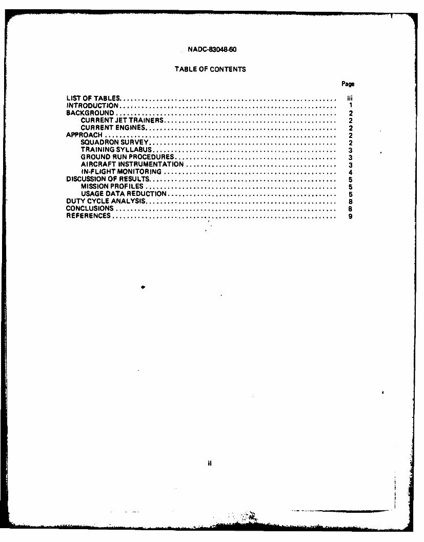
TABLE OF CONTENTS
Page
LIST OF TABLES...................................................... iiINTRODUCTION........................................................ 1BACKGROUND......................................................... 2
CURRENT JET TRAINERS ............................................ 2CURRENT ENGINES ................................................. 2
APPROACH............................................................ 2SQUADRON SURVEY ................................................ 2TRAINING SYLLABUS ............................................... 3GROUND RUN PROCEDURES.......................................... 3AIRCRAFT INSTRUMENTATION ........................................ 3IN-FLIGHT MONITORING............................................. 4
DISCUSSION OF RESULTS ................................................ 5MISSION PROFILES ................................................. 5USAGE DATA REDUCTION............................................ 5
DUTY CYCLE ANALYSIS.................................................. 8CONCLUSIONS.........................................................8aREFERENCES.......................................... 9

NADC-83048-60
LIST OF TABLES
Table Page
I Trainer Squadrons Visited By Location .................................. 2II Jet Trainer Mission Types and Occurrence............................... 3Ill List of Instrumentation Parameters ..................................... 4IV T-2C Training Mission Profiles........................................ 6V TAM4 Training Mission Profiles....................................... 7VI Duty Cycle 1000 Hr. Summaries...................................... 8VII VTX Duty Cycle Definitions......................................... 8
IlA

NADC-83048-60
THIS PAGE INTENTIONALLY LEFT BLANK
IV

NADC-83048-60
INTRODUCTION
The Navy plans to replace the current intermediate and advanced jet trainers (T-2C and TA-4J)with a single new vehicle designatel the VTX. Additionally, the VTX power plant is to be designedfor high reliability to keep its life cycle cost at a minimum.
To ensure an engine of high reliability, the engine specification must define the expected dutycycle so that testing will reflect anticipated operational experience. From a review of the proposedVTX systems, it was very likely that the power plant would be "off the shelf" and not necessarilyqualified to recently revised Navy specifications.
The Naval Air Development Center has established a duty cycle data base which includesfighter, attack, patrol, early warning and training aircraft. NAVAIRSYSCOM has made frequentuse of this Center's expertise on several other engine programs (see references a through e) andrequested, by reference f, a VTX duty cycle based on current jet trainer flight data. These resultswill be used to aueu the engine component part lives and design future accelerated mission testschedules.
El1

NADC-83048-60
BACKGROUND
CURRENT JET TRAINERS
Tne Naval Aviation Training Command provides undergraduate pilots for the fleet replacementsquadrons. Its current program is conducted in three phases: primary, intermediate and advanced.The student pilot generally flies the T-2C aircraft during the intermediate phase and the TAAJ air-craft while completing the advanced phase. The T-2C is a two-place, subsonic, land and carrier-basedtrainer powered by twin J85-GE-4 turbojet engines. The TA-4J is a two-placed, subsonic, land andcarrier-based trainer powered by a single J52-P-8 turbojet engine.
CURRENT ENGINES
The J85-GE-4 is a compact, lightweight engine containing an eight-stage axial flow compressorcoupled directly to a two-stage turbine. It incorporates controlled interstage air bleed, variable inletguide vanes, a through-flow annular combustor, a fixed-area concentric exhaust nozzle, and an inte-grated control system. The engine is rated at 2950 pounds (military power) thrust at see levelstandard conditions. It completed the 150 hour endurance test (MQT) for Navy qualification inMay 1966.
The J52-P-8 is an axial-flow engine with a multi-stage reaction turbine. It has nine through-flow combustion chambers in an annular arrangement. The multi-stage axial compressor consists ofa five-stage low pressure unit and a seven-stage high pressure unit. Both compressors are directlycoupled to a single stage turbine. This engine is rated at 8500 pounds (military power) thrust undersea level standard conditions. It completed the 150 hour endurance test (MQT) for Navy qualifica-tion in June 1965.
APPROACH
SQUADRON SURVEY'
Pilots were surveyed to elicit detailed information concerning mission profiles and standardoperating procedures. Visits were made to the squadron locations, as shown before in reference a, todiscusithe following topics: land-based training missions, trim checks, NATOPS procedures, enginelimits, etc.
Each squadron and respective maintenance shop provided their personnel in support of thesurvey. They answered questions freely and explained both their procedures and problems to anydegree required by the interview. Table I lists the squadrons visited by their respective locations.
Table I. Trainer Squadrons Visited by Location
Base Locations T-2C Squadrons TA-4J Squadrons
NAS Pensacola, FL VT-4, -10 VT-86NAS Meridian, MS VT-9, -19 VT-7NAS Kingsville, TX VT-23 VT-21, 22NAS Chase, TX VT-26 VT-24, 25
2

NADC-83048-60
TRAINING SYLLABUS
Pilots in each squadron follow a specific flight training syllabus. This syllabus containsnumerous mission types for each aircraft. For the T-2C, there were sevV% mission types. The TA-4Jsyllabus had eight mission types. Along with the type of missions, the syllabus provided the numberof flight hours that a student pilot will accumulate. Hence, the frequency of occurrence based onhours was also available in the training syllabus. Table II presents the training syllabus data for theT-2C and the TA-4J.
Table II. Jet Trainer Mission Types and Occurrence
T-2C Mission Percent of TA-4J Mission Percent ofTypes Total Time Types Total Time
Familiarization 31.5 Familiarization 13.6Basic Instruments 4.5 Instruments 7.9Radio Instruments 4.5 Formation 10.1Formation 24.0 Low Level Navigation 4.5Navigation 13.5 Airways Navigation 19.1Gunnery 12.0 Air-Air Combat 12.3Carrier Qualification 10.0 Air-Ground Weapons 14.6
Carrier Qualification 17.9100.0 100.0
GROUND RUN PROCEDURES
Each power plant maintenance shop was visited to determine if ground runs do contributesignificantly to the duty cycle. Low power engine operation associated with aircraft power-up werecited as very infrequent. However, when trims were mentioned, personnel said they may check 2-3engines per week, and further stated that the duration of the trim runs could vary from 30 to 90minutes. For duty cycle calculations, an average value was assumed to account for ground runs.
AIRCRAFT INSTRUMENTATION
The T-2C aircraft was instrumented at this Center to record engine usage and flight conditions.A Datel model DL-2R2 data logger described in reference g was selected; it continuously records upto 64 parameters of analog data on Phillips-type cassettes. Housed in a sealed, weather-proof metalcase, the logger will operate for more than one year on its own lithium battery power supply.Additionally, military type connectors were provided for all analog input channels, which allowedeasy interface with aircraft circuits.
Two additional provisions were made to ensure safe operation of the logger during flight tests.A two-way pressure relief valve permitted flushing of the case with dry air or nitrogen before eachflight to prevent moisture build-up. Also, a thermostatically-controlled heater was incorporated toallow operation down to a temperature of -50°C.
The TA-4J aircraft was instrumented at the Naval Air Test Center (see reference h) formeasurement of engine usage through the parameters lined in Table Il l. A ten watt FM transmitterwas used to relay the acquired usage dota to the telemetry ground station. At the completion ofeach flight, a digital computer tape was made and sent to this Center.
3J

NADC-83048-60
There were two main reasons for selecting this mode of instrumentation. A telemetry packagewas smaller and cheaper to install than the equivalent on-board recorder, and it was immediatelyavailable for use in the proposed aircraft. Shelves were built into the port and starboard wheel-wellsfor the telemetry package. The lower antenna was mounted on the port gun fairing and the upperantenna was mounted behind the cockpit.
IN-FLIGHT MONITORING
Both aircraft were flown on the missions resulting from the squadron survey. Aircraft config-urations matched that of the squadron aircraft. For the T-2C, three pilots were available to producedata. On the TA-4J, one pilot was available to produce data.
Each monitored flight yielded a full record of engine usage. These data were then reduced and
analyzed to provide the basis for developing the duty cycles.
Table III. List of Instrumentation Parameters
I. Low Pressure Rotor Speed 7. Turbine Exit Pressure2. High Pressure Rotor Speed 8. Burner Pressure3. Power Lever Angle 9. Altitude4. Outside Air Temperature 10. Air Speed5. Exhaust Gas Temperature 11. Event Marker6. Engine Pressure Ratio 12. Inlet Total Pressure
4
- N,4

NADC-83048-60
DISCUSSION OF RESULTS
MISSION PROFILES
Discussions regarding mission details at each squadron showed consistency among most pilots.Some differences in local base operations were noted and accounted for in the assembly of repre-sentative training missions. Tables IV and V list these resulting profiles for the T-2C and the TA-4Jrespectively. When questioned about changes to NATOPS defined engine limits, pilots said thatnone currently exist. They are free to select any of the available power settings to perform theiraerial maneuvers.
USAGE DATA REDUCTION
The flight data was reduced by computer programs developed previously in reference a.Tabular data was plotted to allow sufficient editing of each parameter. Some spurious data was re-moved before the usage content was assessed. Subsequently, counting programs summed the numberof starts, throttle cycles, and hot time during each flight. These results were then used to computethe duty cycle.
5

NADC-83048.60
Cq U;00
00
CC C4
LtCC
~0 1~ 0
CO C
0. CN a OO I ,.,
Is E .. - , -
S .0 0 N 78 acE
0...o "-o o 'a
e U E 7', , , U.8 .2 5.2
CL. "- *= "-.o -,, ,-0 Z U ,
€~~~ ~ a %,._. a - =So =_c! c1 l 0L 1-u i L)(D°I-c
, C"
tot
E- E C*
C U. Ug - CL Z* s U ~h 1 . . - 9 "
E~. EU 80 SE.
E4 0. C t 0
70.'.,= o :.x= W.- V . 0-| Eto
to c .0
2U Co c <
Cto
CCc
C- .~ E. S 6

NADC-83048-60
E
EcE c 0 E'ro
'a - 0
00
Z 0. '50 C' E t
'a -. 0
lu c.X C. Ewe .0 .4.- a z UC
E M 0 cU
E 8 1
It u 4-O4 -c Cl nia 0 ;; R i
So~
-- - - - - a ~ a ..
m0E CJIVAIC

NADC-83048-60
DUTY CYCLE ANALYSIS
The duty cycle for the T-2C/J85 was computed using the seven missions, a maintenance trim,and the flight data. Similarly, the duty cycle for the TA-4J/J52 was calculated using eight missions,a maintenance trim, and the flight data. Thus, for a 1000 hours operating time, the resulting totalnumber of starts, throttle cycles, and hot time are shown in Table VI.
Table VI. Duty Cycle 1000 Hr. Summaries
Aircraft Number Throttle HotType/Model of Starts Cycles Time (hr.)
T-2C 666 4027 83.4TA-4J 524 4480 116.0
Notably, the T-2C duty cycle has a higher cyclic content than the TA-4J due to the greaternumber of missions (or start-stop cycles). This was principally because of a lower average flight timefor the T-2C. Conversely, the TA-4J shows significantly more hot time, because the TA-4J is usedexclusively for air combat maneuvering practice and air-ground weapons delivery. These twomissions tend to drive the duty cycle because of their large hot time content.
The development of the duty cycle for a VTX trainer aircraft must be viewed from a newperspective. The previous analysis shows the T-2C used in one manner, and the TA-4J used in asignificantly different one. Since the VTX aircraft will be used in both roles, it will be required tofunction under both requirements at once. Thus, the highest values must be used to define theexpected duty cycle for the VTX propulsion system. Table VII defines the duty cycle for the VTX.
Table VII. VTX Duty Cycle Definitions
Number Throttle Hotof Starts Cycles Time (hr.)
666 4480 116.
CONCLUSIONS
Mission profiles and maintenance procedures for the T-2C/J85 intermediate trainer and theTA-4J/J52 advanced trainer were investigated. A test aircraft of each model was instrumented toprovide recorded usage data over the surveyed missions. From the engine usage tapes, a data basehas been established from which to develop a trainer duty cycle.
The duty cycle for the present J85-GE4 and J52-P-8 was calculated. Using the mostdemanding criteria from both data, a duty cycle was derived for the proposed VTX replacementtrainer aircraft. When the Navy acquires the new trainer engine, the propulsion system specificationshould include this VTX duty cycle as a more realistic design criteria. Any future mission testsshould also be compared with this criteria to reveal their usage severity.
8

NADC-83048-60
REFERENCES
a. "Simulated Mission Endurance Test (SMET) for an Aircraft Engine to be used in a Fighter/Attack Role", NADC-77051-30 dated 23 April 1979.
b. "Operational Environment for Naval Aircraft Gas Turbines", Journal of Aircraft, Volume 16,October 1979, p. 729.
c. "Survey and Update of the F-14A Mission Profiles for TF30 Engine Usage", NADC-82039-60dated 30 April 1982.
d. "Investigation of F/A-18A Engine Throttle Usage and Parametric Sensitivities",ASME No. 83GT-64.
e. "Survey of P-3C Mission Profiles for the Development of the T56-A-14 Duty Cycle",NADC-83028-60 dated 14 June 1983.
f. AIRTASK A5365360, "Operational Environment for Aircraft Engines", Work Unit No. 139D,13 Sept. 1978.
g. "Data Logger DL-2 Instruction Manual", dated February 1977.
h. "Instrumentation System for the J52-P-6 and P-8 Mission Profiles", by J. H. Dutton, Jr., dated5 Oct. 1978.
9
-'S

NADC.630484
THIS PAGE INTENTIONALLY LEFT BLANK
10