Embed Size (px)
Citation preview
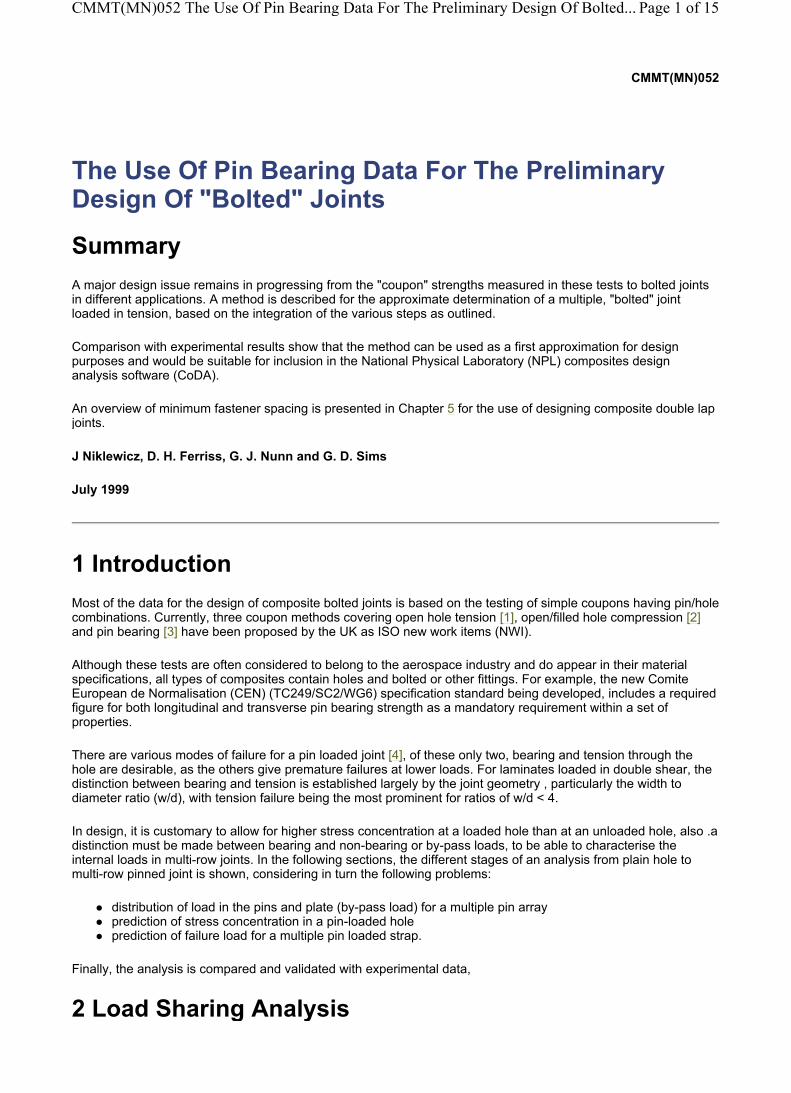
CMMT(MN)052
The Use Of Pin Bearing Data For The Preliminary Design Of "Bolted" Joints
Summary A major design issue remains in progressing from the "coupon" strengths measured in these tests to bolted joints in different applications. A method is described for the approximate determination of a multiple, "bolted" joint loaded in tension, based on the integration of the various steps as outlined.
Comparison with experimental results show that the method can be used as a first approximation for design purposes and would be suitable for inclusion in the National Physical Laboratory (NPL) composites design analysis software (CoDA).
An overview of minimum fastener spacing is presented in Chapter 5 for the use of designing composite double lap joints.
J Niklewicz, D. H. Ferriss, G. J. Nunn and G. D. Sims
July 1999
1 Introduction Most of the data for the design of composite bolted joints is based on the testing of simple coupons having pin/hole combinations. Currently, three coupon methods covering open hole tension [1], open/filled hole compression [2] and pin bearing [3] have been proposed by the UK as ISO new work items (NWI).
Although these tests are often considered to belong to the aerospace industry and do appear in their material specifications, all types of composites contain holes and bolted or other fittings. For example, the new Comite European de Normalisation (CEN) (TC249/SC2/WG6) specification standard being developed, includes a required figure for both longitudinal and transverse pin bearing strength as a mandatory requirement within a set of properties.
There are various modes of failure for a pin loaded joint [4], of these only two, bearing and tension through the hole are desirable, as the others give premature failures at lower loads. For laminates loaded in double shear, the distinction between bearing and tension is established largely by the joint geometry , particularly the width to diameter ratio (w/d), with tension failure being the most prominent for ratios of w/d < 4.
In design, it is customary to allow for higher stress concentration at a loaded hole than at an unloaded hole, also .a distinction must be made between bearing and non-bearing or by-pass loads, to be able to characterise the internal loads in multi-row joints. In the following sections, the different stages of an analysis from plain hole to multi-row pinned joint is shown, considering in turn the following problems:
distribution of load in the pins and plate (by-pass load) for a multiple pin array prediction of stress concentration in a pin-loaded hole prediction of failure load for a multiple pin loaded strap.
Finally, the analysis is compared and validated with experimental data,
2 Load Sharing Analysis
Page 1 of 15CMMT(MN)052 The Use Of Pin Bearing Data For The Preliminary Design Of Bolted...
23/06/2005http://midas.npl.co.uk/midas/content/mn052.html
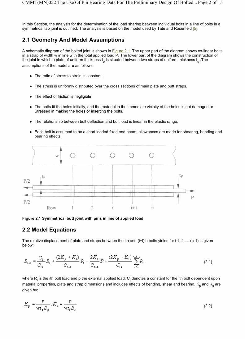
In this Section, the analysis for the determination of the load sharing between individual bolts in a line of bolts in a symmetrical lap joint is outlined. The analysis is based on the model used by Tate and Rosenfeld [5].
2.1 Geometry And Model Assumptions
A schematic diagram of the bolted joint is shown in Figure 2.1. The upper part of the diagram shows co-linear bolts in a strap of width w in line with the total applied load P. The lower part of the diagram shows the construction of the joint in which a plate of uniform thickness tp is situated between two straps of uniform thickness ts .The assumptions of the model are as follows:
The ratio of stress to strain is constant.
The stress is uniformly distributed over the cross sections of main plate and butt straps.
The effect of friction is negligible
The bolts fit the holes initially, and the material in the immediate vicinity of the holes is not damaged or Stressed in making the holes or inserting the bolts.
The relationship between bolt deflection and bolt load is linear in the elastic range.
Each bolt is assumed to be a short loaded fixed end beam; allowances are made for shearing, bending and bearing effects.
Figure 2.1 Symmetrical butt joint with pins in line of applied load
2.2 Model Equations
The relative displacement of plate and straps between the ith and (i+l)th bolts yields for i=l, 2,.... (n-1) is given below:
where Ri is the ith bolt load and p the external applied load. Cj denotes a constant for the ith bolt dependent upon material properties, plate and strap dimensions and includes effects of bending, shear and bearing. Kp and Ks are given by:
(2.1)
(2.2)
Page 2 of 15CMMT(MN)052 The Use Of Pin Bearing Data For The Preliminary Design Of Bolted...
23/06/2005http://midas.npl.co.uk/midas/content/mn052.html

where p is the hole spacing or pitch and Ep and Es denote Young's modulus for the plate and strap respectively. The overall equilibrium condition gives:
Each bolt constant Cj has contributions from the various beam mechanisms in operation:
where
and Ab = πd2/4, Ib = πd4/64 and d is the bolt diameter
In the above equations, Ebb and Ebbr are Young' s moduli for the bolt under bending and bolt under bearing respectively. Esbr and Epbr are the bearing moduli for the strap and plate, assumed equal to the compressive moduli of the respective materials. Assuming that the bolt diameter d is the same for each, then bolts of the same material imply that Ci = Ci+1 = C.
For purposes of the present implementation, it is assumed that:
The analysis can be extended to allow for the presence of bolts in several lines parallel to the applied load as shown in Figure 2.2. In addition to the previous assumptions, it is assumed that the bolts in any transverse row are loaded equally and that the bolts in any transverse row are identical, although this latter assumption is not explicitly stated in the Tate and Rosenfeld paper [5].
The corresponding form of (2.1) is:
where Ni denotes the number of bolts in the ith row.
(2.3)
Ci = Cbs + Cbb + Cbbr + Cpbr (2.4)
(shear effect)
(bending effect)
(bearing effect)
(plate bearing effect)
Epbr = Ep, Esbr = Es, Ebbr, Ebb = Eb (2.5)
(2.6)
Page 3 of 15CMMT(MN)052 The Use Of Pin Bearing Data For The Preliminary Design Of Bolted...
23/06/2005http://midas.npl.co.uk/midas/content/mn052.html

Figure 2.2 Symmetrical joint with multiple pins
2.3 Solution Of The Model Equations
To enable Rj to be evaluated, Equation 2.1 is rearranged:
where:
As the bolts are normally of the same material.
These equations are solved using a form of Gauss Seidel iteration as follows. An initial estimate to each Ri is made; an obvious choice is to use Ri = P/n. Using i = 1,2 etc in turn in Equation 2.7 enables new estimates to be made for the Rj up to Rn-1. Finally Equation 2.8 provides a new estimate for Rn.
This whole process is repeated until relative changes from one iteration to the next are less than some specified tolerance, usually 1 × 10⁻⁶, at which point the calculation for the bolt loads Rj is considered completed. The by-pass loads Psi are determined from:
i = 1, 2....n-1 (2.7)
(2.8)
(2.9)
Page 4 of 15CMMT(MN)052 The Use Of Pin Bearing Data For The Preliminary Design Of Bolted...
23/06/2005http://midas.npl.co.uk/midas/content/mn052.html

2.4 Validation Of Tate And Rosenfeld
Finite element analysis (PEA) as well as electronic speckle pattern interferometry (ESPI) [6] have been used to validate the Tate and Rosenfeld method [5]. Table 2.1 compares load share values between Tate and Rosenfeld and non-linear contact PEA (using orthotropic values) for a double lap four pin pultruded joint.
Table 2.1 Tate and Rosenfeld (T&R) Prediction compared to FEA
3 Failure Loads In Multi-Row Joints The main objective of using multi-row joints is to minimise the peak bearing load, avoiding the cut-off due to bearing as shown in Figure 3.3 [7]. To achieve improved strength the joint has to be designed to ensure even load sharing between the fasteners. If the joint has been correctly designed to reduce bearing loads, failure under tensile loading will occur in net tension. However there are two sources of tensile stress at the edge of a fastener hole:
the load reacted out on the fastener by bearing the load bypassing the fastener to be reacted out on other fasteners along the joint
An experimental approach to finding the allowable load on a composite joint is to produce a plot, such as in Figure 3.4, in which the outer envelope of allowable gross strain eu (away from the fastener hole) is shown as a function of the bearing stress σb. All that is needed is to establish by analysis the peak bearing stress at the critical hole in the joint. In Figure 3.4 the allowable gross strain fore pure by-pass is shown as 4000 microstrain, reducing to around 3000 microstrain at the bearing cut off. These envelope plots can be produced by measuring:
the failure stress of a joint element with an unloaded hole that should fail in tension at the fastener hole. Methods such as the Whitney Nuismer [8-9] failure criteria can also be used if the characteristic distance is known,
the bearing stress in a wide strip (six times the diameter of the hole) forced to fail in bearing,
the failure stress of a narrow strip (three times the hole diameter) designed to fail in tension at the hole at some combinations of by-pass and bearing.
Page 5 of 15CMMT(MN)052 The Use Of Pin Bearing Data For The Preliminary Design Of Bolted...
23/06/2005http://midas.npl.co.uk/midas/content/mn052.html

Figure 3.3 Plot of joint efficiency versus d/w for single fastener joints [7]
For tension loading the conditions for onset of damage are similar to those shown schematically in Figure 3.4,indicatiing a cut-off of tension reacted bearing strength for net tension failures as the magnitude of the by-pass stress increases. The results are reasonably explained by two straight line plots, one for bearing failures and the other for net tension.
Figure 3.4 Design allowable for bearing-bypass interaction under tensile loading. [7]
Under compression loading, the behaviour is markedly different as the bolt (if the clearances are small) can support the walls of the hole, transmitting part of the load directly and thus delaying the onset of net compression. The predominant failure mode is therefore compression reacted bearing failure.
An analytical approach for multi-pin joints under tension in a strip w can be used, based on the hypothesis of linear interaction equation between the net tension by-pass and bearing stresses (found with the Tate and Rosenfeld method) using the relationship as shown in Equation 3.1 :
In which σtu is the basic laminate strength, al is the by-pass stress at the hole under consideration Ktb is the bearing stress concentration factor and Ktc is the by-pass concentration factor found from experimentation or using the Whitney Nuismer failure criteria.
Based on the work of others Hart-Smith [4] showed that the stresses associated with σt the elastic concentration factor (Kte) for an unloaded hole in an isotropic strip width is given by:
(3.1)
Page 6 of 15CMMT(MN)052 The Use Of Pin Bearing Data For The Preliminary Design Of Bolted...
23/06/2005http://midas.npl.co.uk/midas/content/mn052.html

To allow for stress reduction in composites at failure loads, an approximate linear relationship is used between Kte and Ktc Since the two coefficients must be equal at Kte = 1 the equation used is:
where c is the correlation coefficient for that particular laminate, environmental conditions and geometry of the joint. A value of C=0 indicates full relief of the stress concentration, whereas C=1 indicates a brittle material.
Using this c factor the stress concentration factor Ktc for a loaded hole can be found combining Equations 3.3 and 3.4 where the isotropic stress concentration factor for a loaded hole is:
As the tensile failure load with no by-pass can be expressed either in terms of net section or in terms of the contact area dt we have:
This gives an expression (Equation 3.6) for the bearing concentration factor:
4 Four Pin Double-Lap Tests To validate the above method, a variety of tests were carried out from single row multi pin tests to multi row arrays of pin arrangements with differing w/d ratios, pitch distances, numbers of pins and materials.
Initially four pin double lap joints were tested at a range of w/d values as shown in Figure 4.1. A pin loaded specimen was chosen as this is the simplest stress distribution as well as the worst case loading condition. Four pins were chosen so that the load sharing could be favourably demonstrated.
(3.2)
(3.3)
(3.4)
(3.5)
(3.6)
Page 7 of 15CMMT(MN)052 The Use Of Pin Bearing Data For The Preliminary Design Of Bolted...
23/06/2005http://midas.npl.co.uk/midas/content/mn052.html

Figure 4.1 Relevant dimensions on 4-pin double-lap joint.
Figures 4.2 to 4.4 compare the predicted failure loads with experimental values obtained for the three materials were the pitch p is kept constant. All the specimens failed in net tension at pin 1, as expected.
Figure 4.2 Results of pultruded 4-pin double-lap pin tests
Page 8 of 15CMMT(MN)052 The Use Of Pin Bearing Data For The Preliminary Design Of Bolted...
23/06/2005http://midas.npl.co.uk/midas/content/mn052.html

Figure 4.3 Results of woven glass-fibre epoxy 4-pin double-lap pin tests
Figure 4.4 Results of carbon-fibre/epoxy 4-pin double-lap pin tests
Calculations for four pin single row joints were compared to pin and bolted joints as shown in Figure 4.5. NPL has
Page 9 of 15CMMT(MN)052 The Use Of Pin Bearing Data For The Preliminary Design Of Bolted...
23/06/2005http://midas.npl.co.uk/midas/content/mn052.html

shown [10] that torquing up a bolt can increase the bearing capacity of a joint by over 50% for certain materials and lay-ups. The methods described in Chapters 2 and 3 predict the maximum pin loaded stress of the joint, as this would be the worst case for design.
Figure 4.5 Comparison of pin/bolted and predicted loads for a glass-fibre epoxy material
Page 10 of 15CMMT(MN)052 The Use Of Pin Bearing Data For The Preliminary Design Of Bolt...
23/06/2005http://midas.npl.co.uk/midas/content/mn052.html
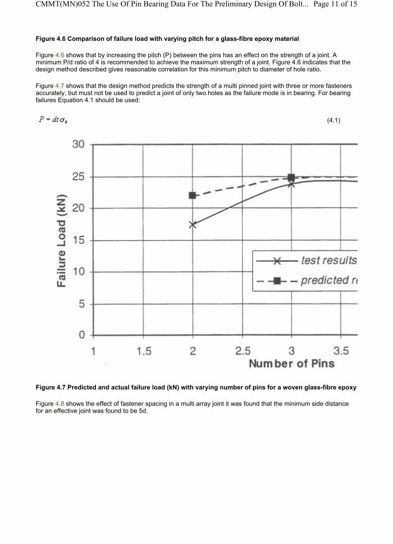
Figure 4.6 Comparison of failure load with varying pitch for a glass-fibre epoxy material
Figure 4.6 shows that by increasing the pitch (P) between the pins has an effect on the strength of a joint. A minimum P/d ratio of 4 is recommended to achieve the maximum strength of a joint. Figure 4.6 indicates that the design method described gives reasonable correlation for this minimum pitch to diameter of hole ratio.
Figure 4.7 shows that the design method predicts the strength of a multi pinned joint with three or more fasteners accurately, but must not be used to predict a joint of only two holes as the failure mode is in bearing. For bearing failures Equation 4.1 should be used:
Figure 4.7 Predicted and actual failure load (kN) with varying number of pins for a woven glass-fibre epoxy
Figure 4.8 shows the effect of fastener spacing in a multi array joint it was found that the minimum side distance for an effective joint was found to be 5d.
(4.1)
Page 11 of 15CMMT(MN)052 The Use Of Pin Bearing Data For The Preliminary Design Of Bolt...
23/06/2005http://midas.npl.co.uk/midas/content/mn052.html
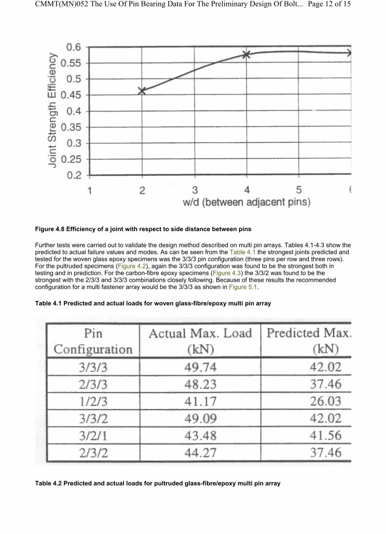
Figure 4.8 Efficiency of a joint with respect to side distance between pins
Further tests were carried out to validate the design method described on multi pin arrays. Tables 4.1-4.3 show the predicted to actual failure values and modes. As can be seen from the Table 4.1 the strongest joints predicted and tested for the woven glass epoxy specimens was the 3/3/3 pin configuration (three pins per row and three rows). For the pultruded specimens (Figure 4.2), again the 3/3/3 configuration was found to be the strongest both in testing and in prediction. For the carbon-fibre epoxy specimens (Figure 4.3) the 3/3/2 was found to be the strongest with the 2/3/3 and 3/3/3 combinations closely following. Because of these results the recommended configuration for a multi fastener array would be the 3/3/3 as shown in Figure 5.1.
Table 4.1 Predicted and actual loads for woven glass-fibre/epoxy multi pin array
Table 4.2 Predicted and actual loads for pultruded glass-fibre/epoxy multi pin array
Page 12 of 15CMMT(MN)052 The Use Of Pin Bearing Data For The Preliminary Design Of Bolt...
23/06/2005http://midas.npl.co.uk/midas/content/mn052.html

Table 4.3 Predicted and actual loads for quasi-isotropic carbon-fibre/epoxy multi pin array
5 Mechanical Joint Guidelines In general, the best fastened joints in fibrous composites still impose a loss in strength of about half the basic material strength
If a laminate is dominated by d) fibres with few transverse fibres it is most likely to fail by shearing out of the composite. The minimum edge distance used for multi directional composites should be e!d > 3 (see Figure 5.1) to avoid composite shear out.
A minimum of 40% of ±45° plies should be used with a minimum 10% of 90° to achieve highest bearing stresses. Optimum lay-up patterns for maximised fastener strength are found when a quasi-isotropic lay-up is used.
Net tension failure (Figure 3.3) is influenced by the tensile strength of the fibres at fastened joints, which is maximised when the fibre spacing is approximately four to five times the fastener diameter (Figure 4.8). Smaller spacing results in cutting to many fibres while larger spacing results in bearing failures. Minimum fastener spacing is shown in Figure 5.1.
Use two row joints where possible. The low ductility of composite materials confines most of the load transfer to the outer fasteners, if more than two rows are needed bearing Iby-pass procedures such as the one in Chapters 2 and 3 should be used.
If possible double lap joints should be used in designing composite joints as the eccentricity in the load path of single lap joints leads to a non uniform bearing load on the fasteners reducing the strength of the joint considerably.
Page 13 of 15CMMT(MN)052 The Use Of Pin Bearing Data For The Preliminary Design Of Bolt...
23/06/2005http://midas.npl.co.uk/midas/content/mn052.html

Figure 5.1 Minimum fastener spacing and edge distance
6 Conclusions A method for the approximate determination of a multiple array joint loaded in tension has been described, based on the integration of the various steps shown in Sections 2 to 3. Comparisons with experimental results, shown in Section 4, indicated that the method can be used as an approximation for design purposes for a strip that is designed to fail in net tension. It is planned to use this approach to prepare a design module within the CoDA software [11] for bolted joints.
An overview of minimum fastener spacing has been validated in Chapter 4 and presented in Chapter 5 for the use of designing composite double lap joints.
References 1. ISO NWI 712, Fibre reinforced plastic composites -Determination of the open-hole (notched) tensile
strength. 2. ISO NWI 711, Fibre reinforced plastic composites -Determination of the open- holes (notched) and filled
hole compressive strength. 3. ISO NWI 714, Fibre reinforced plastic composites -Determination of the pin- bearing strength. 4. HART-SMITH I., "Bolted joints in graphite-epoxy composites", Douglas Aircraft Company, NASA CR-
144899,(1977). 5. TATE and ROSENFELD 'Preliminary investigation of the loads carried by individual bolts in bolted joints.
NACA Technical Note No 1051, (1946). 6. NIKLEWICZ J. and SIMS G. D., " Use of laser speckle holography to validate structural element coupon
test methods", ECCTS-4, 227-234, (1998). 7. HART-SMITH J., "Mechanically fastened joints for advanced composites, phenomenological considerations
and simple analyses", Fibrous composites in structural design, Plenium Press, (1993). 8. WHITNEY J. and NUISMER R., "Stress fracture criteria for laminated composites containing stress
concentrations", J. Composite Materials, 8,253-265, (1974). 9. SIMS G. D., PAYNE D. R. and FERRISS D. H., "Analysis and experimental validation of structural element
test methods", ECCM-7/CTS3, 73-78, Volume 2, (1996). 10. J NIKLEWICZ, G. J. NUNN AND G D SIMS, "Evaluation of in-plane bolted connections", CMMT (MN) 053,
July 1999. 11. COMPOSITES DESIGN ANALYSIS (CoDA), NPL PC windows software, (1996).
Acknowledgement The work reported in this measurement note was carried out in the Composites Performance and design Project as part of the "Materials Measurement Programme", a programme of underpinning research financed by the
Page 14 of 15CMMT(MN)052 The Use Of Pin Bearing Data For The Preliminary Design Of Bolt...
23/06/2005http://midas.npl.co.uk/midas/content/mn052.html

United Kingdom Department of Trade and Industry.
The Authors would like to express their gratitude to the participants, without whose effort the round-robin would not have been possible, and to the members of the Project team especially Richard Shaw and Geoffrey Nunn, whose contributions have made this report possible.
For further information contact:
© Crown Copyright 1999. Reproduced by permission of the Controller of HMSO.
Dr. G D SimsCentre for Materials Measurement and TechnologyTel: 020 8943 6564Email: [email protected]
Experts National Physical LaboratoryQueens RoadTeddingtonMiddlesexUnited KingdomTW11 0LW Tel: 020 8977 3222Fax: 020 8943 6458Email: [email protected]
CMMT(MN)052The Use Of Pin Bearing Data For The Preliminary Design Of "Bolted" JointsJuly 1999
Page 15 of 15CMMT(MN)052 The Use Of Pin Bearing Data For The Preliminary Design Of Bolt...
23/06/2005http://midas.npl.co.uk/midas/content/mn052.html