Embed Size (px)
Citation preview

The University of Texas at Arlington
Lecture 11 Timers, Capture/Compare/PWM
CSE 3442/5442

2 2
PIC Timers
• PIC18 family microcontrollers have two to five timers on board.
• Timers can be used to generate time delays or to count (outside) events happening.
• Some timers can also be used to control timing of other peripherals (the designer needs to pay attention to that).
• Every timer needs a clock that will make it to count. • PIC18 timers have the option to use at most ¼ of the
main clock’s frequency or use a separate external signal for clocking.
• Timers can overload several pins on the microcontroller

3 3
Timer0
• Timer-0 can be used as an 8-bit or as a 16-bit timer. • Thus, two SFR are used to contain the count:
• Each timer has a control register: T0CON for timer 0 • Timer SFR-s are read/write registers but do not have
immediate access. • Timer clocks make timers count; the timer clock can be
internal or external.

4 4
Timer-0 Control Register T0CON
• Note that timer interrupt enable/flag bits are in registers related to interrupts (e.g., INTCON)
• When the timer overflows, TMR0IF is set.
• 16- vs. 8-bit timer • Prescalers are
useful for large time delays
5 5
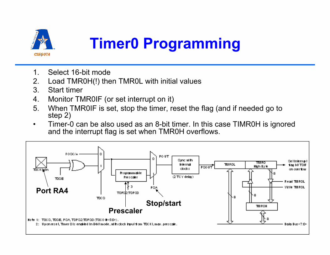
Timer0 Programming
1. Select 16-bit mode 2. Load TMR0H(!) then TMR0L with initial values 3. Start timer 4. Monitor TMR0IF (or set interrupt on it) 5. When TMR0IF is set, stop the timer, reset the flag (and if needed go to
step 2) • Timer-0 can be also used as an 8-bit timer. In this case TIMR0H is ignored
and the interrupt flag is set when TMR0H overflows.
Prescaler Stop/start
Port RA4
6 6
Timer1
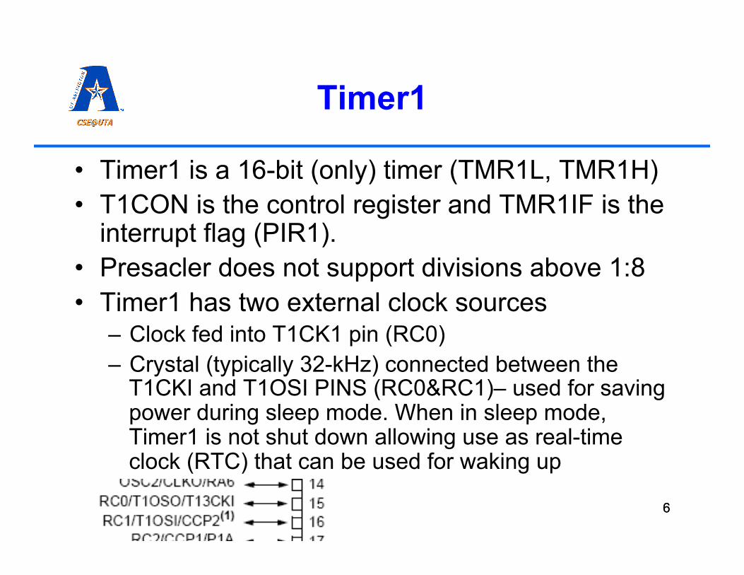
• Timer1 is a 16-bit (only) timer (TMR1L, TMR1H) • T1CON is the control register and TMR1IF is the
interrupt flag (PIR1). • Presacler does not support divisions above 1:8 • Timer1 has two external clock sources
– Clock fed into T1CK1 pin (RC0) – Crystal (typically 32-kHz) connected between the
T1CKI and T1OSI PINS (RC0&RC1)– used for saving power during sleep mode. When in sleep mode, Timer1 is not shut down allowing use as real-time clock (RTC) that can be used for waking up
7 7
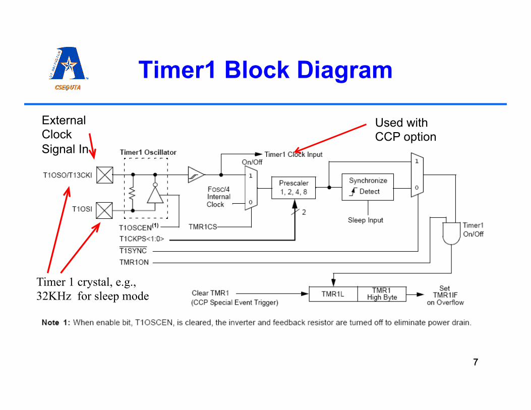
Timer1 Block Diagram
Used with CCP option
External Clock Signal In
Timer 1 crystal, e.g., 32KHz for sleep mode

8 8
Timer 1 Control Register T1CON
• RD16=1 is the only option in Timer0 (to avoid changes in Timer1H while Timer1L is read/write a temporary register is used)
• Timer-1 can be used as i) timer, ii) as synchronous counter (T1SYNC), iii) asynchronous counter

9 9
Timer2
• Timer2 is an 8-bit (only) timer (TMR2) • Timer2 has a period register PR2; Timer2 can be set to
count only to PR2 and set TMR2IF then. • Clock source is only Fosc/4 (thus, Timer2 cannot be
used as a counter) ; prescalers and postscalers (count on interrupt) are available.
more about these shortly

10 10
Timer2 Control Register T2CON

11 11
Timer3
• Timer3 is a 16-bit (only) timer (TMR3L, TMR3H) • Can work with CCP peripheral (later) • Can use same external source as timer1 • Can be used as timer, ascynchronous, or synchronous counter

12 12
Timer3 Control Register T3CON
See soon

13 13
Using PIC18 Timers for Capture, Compare, and PWM

14
PWM Basics
• PWM = Pulse width modulation • Digital signals have two distinct levels: high and low • Each of these levels is usually represented by a voltage,
e.g., in PIC low is 0V and high is VCC (e.g., 5V). • A temporal digital signal changes with time from low to
high and back. • Thus we can describe temporal digital signals with a
series of values representing the time for which they stay in one state.
• Periodic temporal digital signals have a distinct frequency (the inverse of the time between two consecutive rising edges)
15
PWM Basics (cont’d)
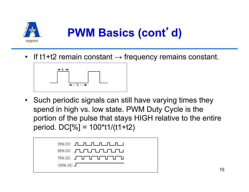
• If t1+t2 remain constant → frequency remains constant.
• Such periodic signals can still have varying times they spend in high vs. low state. PWM Duty Cycle is the portion of the pulse that stays HIGH relative to the entire period. DC[%] = 100*t1/(t1+t2)

16
PWM Basics (cont’d)
• There are various sensors that provide their output as PWM signals, where the DC corresponds to the reading.
• There are various actuators that work well with a PWM input.
• Actually, an appropriate RC filter (Integrator) can make an analog signal out of a PWM digital signal
R
C PWM Analog
17
Capture, Compare, PWM Modules
• PIC18 microcontrollers can have up to 5 CCP modules. • Compare enables the counter value of timers to be
compared to a 16bit register, and if equal perform an action.
• Capture can use an external input to copy timer values into a 16-bit register. Thus, Capture provides the capability of measuring the period of a pulse.
• PWM – pulse width modulation, can be used as a quasi analog output (a timed digital output with duty cycle setting).
• These modules are great for driving motors, or reading encoders.
• For DC motor control some of the CCPs have been enhanced and are called ECCP

18 18
Timers and CCP Features
• Timers 1 and 3 can be used for capture and compare features
• Timer 2 is used for PWM • As shown before, T3CON is used to chose
the timer for C/C
These rules do not always apply – have to check the specific PIC18 datasheet

19 19
CCP Module Basics
• Each CCP module has three registers associated with it: – CCPxCON controlling the modes – CCPxL and CCPxH as a 16-bit compare/
capture/PWM duty cycle register • Each CCP module has a pin associated
with it (input or output)

20 20
CCP Module Control CCPxCON
prescalers

21
Compare Mode
• The CCPRxH:CCPRxL is loaded by the user • If Timer1 TMR1H:TMR1L (or Timer3 – T3CON)
count becomes equal to the above set value then the Compare module can: – Drive the CCPx pin high (CCPx config’d as out) – Drive the CCPx pin low (CCPx config’d as out) – Toggle the CCPx pin (CCPx config’d as out) – Trigger a CCPxIF interrupt and clear the timer – CCP2 can be used to kick off the A/D converter
21

22
Compare Mode Programming
0. Set up CCP interrupt if needed 1. Initialize CCPxCON for compare 2. Set timer source (T3CON) 3. Initialize CCPRxH:CCPRxL 4. Make sure CCPx pin is output if used (setting
appropriate bits TRISB or TRISC) 5. Initialize Timer1 (or Timer3) 6. Start Timer1 (or Timer3) 7. Monitor CCPxIF or make sure interrupt is
handled 22

23
Capture Mode
• The CCPx pin is set as input (with the appropriate TRIS) • When an external event triggers the CCPx pin, then the
TMR1H:TMR1L (or Timer3) values will be loaded into CCPRxH:CCPRxL
• Four options for CCPx pin triggering: – Every falling edge – Every rising edge – Every fourth rising edge – Every fourth falling edge
• Typical applications are measuring frequency or pulsewidth.
23

24
Capture Mode Programming for Frequency Measurement
1. Initialize CCPxCON for capture 2. Make CCPx pin an input pin (TRISB/TRISC) 3. On the first rising edge, Timer1 is loaded into
CCPRxH:CCPRxL ; remember values. 4. On the next rising edge, Timer1 is loaded again into
CCPRxH:CCPRxL ; subtract previous values from current values.
5. You have now the period of the signal captured by timer ticks. Some basic math will give you frequency
24

25
Capture Mode Programming for Measuring PWM Duty Cycle
1. Initialize CCPxCON for capture 2. Make CCPx pin an input pin (TRISB/TRISC) 3. Reset Timer1 4. On the rising edge, Timer1 is started and mode is set
to falling edge detction 5. On the falling edge the CCPRxH:CCPRxL should be
saved, CCP should be set to rising edge detection 6. On the rising edge CCPRxH:CCPRxL is saved. Now
we have measurements for t1 and t2. 7. DC cycle can be calculated while new measurement is
prepared (if continuous measuring is needed) • Hint: interrupts can help 25
26 26
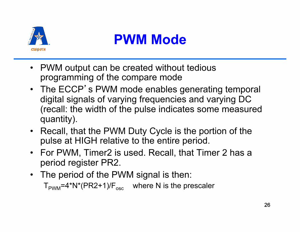
PWM Mode
• PWM output can be created without tedious programming of the compare mode
• The ECCP’s PWM mode enables generating temporal digital signals of varying frequencies and varying DC (recall: the width of the pulse indicates some measured quantity).
• Recall, that the PWM Duty Cycle is the portion of the pulse at HIGH relative to the entire period.
• For PWM, Timer2 is used. Recall, that Timer 2 has a period register PR2.
• The period of the PWM signal is then: TPWM=4*N*(PR2+1)/Fosc where N is the prescaler

27 27
PWM Mode - Frequency
• Since most of the time we know what frequency we want to set it we need to set PR2: PR2=Fosc/(4*N*FPWM) – 1
• We see thus that the maximum PWM frequency is about a quarter of the clock while the minimum is about Fosc/16382
28 28
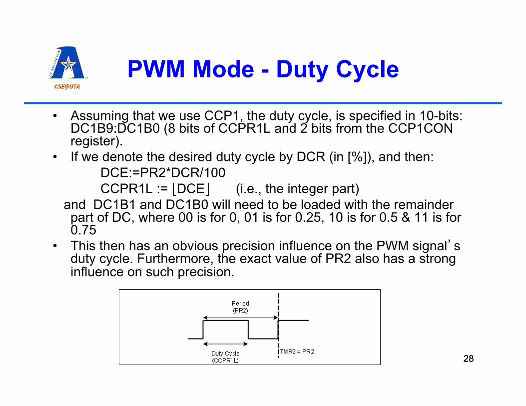
PWM Mode - Duty Cycle
• Assuming that we use CCP1, the duty cycle, is specified in 10-bits: DC1B9:DC1B0 (8 bits of CCPR1L and 2 bits from the CCP1CON register).
• If we denote the desired duty cycle by DCR (in [%]), and then: DCE:=PR2*DCR/100 CCPR1L := ⎣DCE⎦ (i.e., the integer part)
and DC1B1 and DC1B0 will need to be loaded with the remainder part of DC, where 00 is for 0, 01 is for 0.25, 10 is for 0.5 & 11 is for 0.75
• This then has an obvious precision influence on the PWM signal’s duty cycle. Furthermore, the exact value of PR2 also has a strong influence on such precision.

29 29
PWM Mode - Programming
1. Set PWM period by setting PR2 and T2CON (prescaler)
2. Set PWM duty cycle by calculating and writing CCPRxL; (remember the remainder)
3. Set the CCPx as output 4. Clear TMR2 5. Load the remainder from step 2 into CCPxCON and
set CCPx to PWM mode 6. Start Timer 2. • This will result in a proper periodic temporal digital
signal (no need to use goto-s)

30
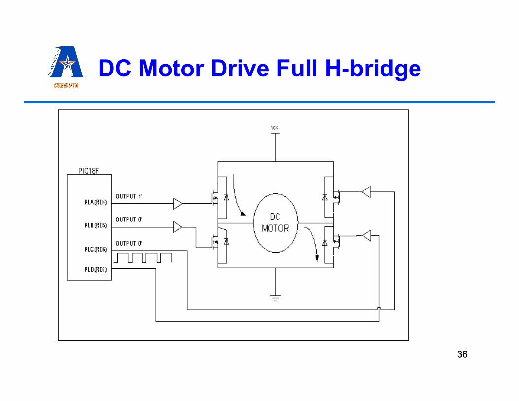
Driving DC Motors
• Brushed DC motors are common • DC motors can run in both direction based on polarity on
the two leads. • DC motors run continuously when voltage is applied
(rpm, voltage, torque, and power are all characteristics that need to be looked up in a catalog).
• How could we create circuitry that lets them rotate in both direction and with controlled speed?
31 31
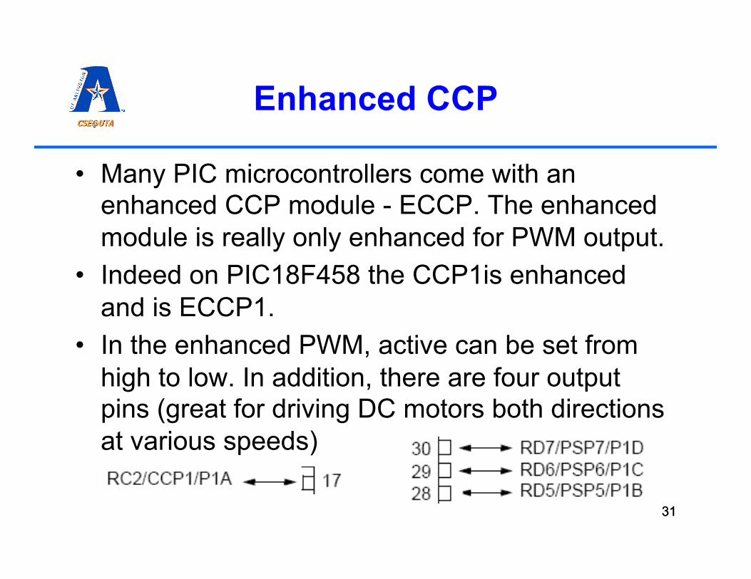
Enhanced CCP
• Many PIC microcontrollers come with an enhanced CCP module - ECCP. The enhanced module is really only enhanced for PWM output.
• Indeed on PIC18F458 the CCP1is enhanced and is ECCP1.
• In the enhanced PWM, active can be set from high to low. In addition, there are four output pins (great for driving DC motors both directions at various speeds)
32
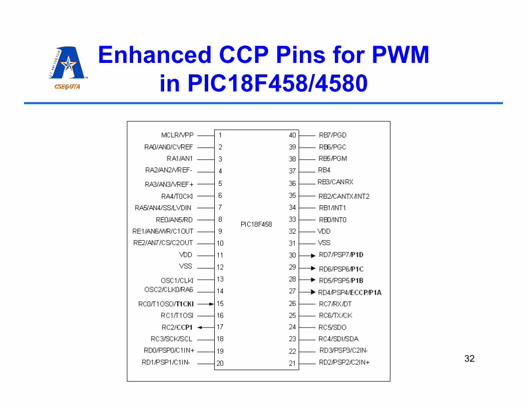
Enhanced CCP Pins for PWM in PIC18F458/4580

33 33
Enhanced CCP Control

34 34
Enhanced CCP Block Diagram

35 35
DC Motor Drive Half bridge
36 36
DC Motor Drive Full H-bridge

37 37
DC Motor Drive Full H Bridge

38 38
Bridge Timing Diagrams

39
How About Other Types of Motors?
• Common other types of motors that we would like to control are: stepper motors (steppers) and servo motors (servos).
• Steppers are usually used when precise rpms are needed or when precise angles need to be turned to.
• Servos are usually used to make motors turn precisely to an angle with loads on them that could try to move the motor away.

40
Stepper Motors
• Stepper motors are called that way as the user can turn them in small little precise steps.
• For example a 24 step/revolution (spr) motor has a 15° step angle, while a 48spr motor has a 7.5° angle.
• Maximum speed is usually given in steps per second.
• Holding torque determines how much torque is required to move the motor away from its position when control is applied to it.
41
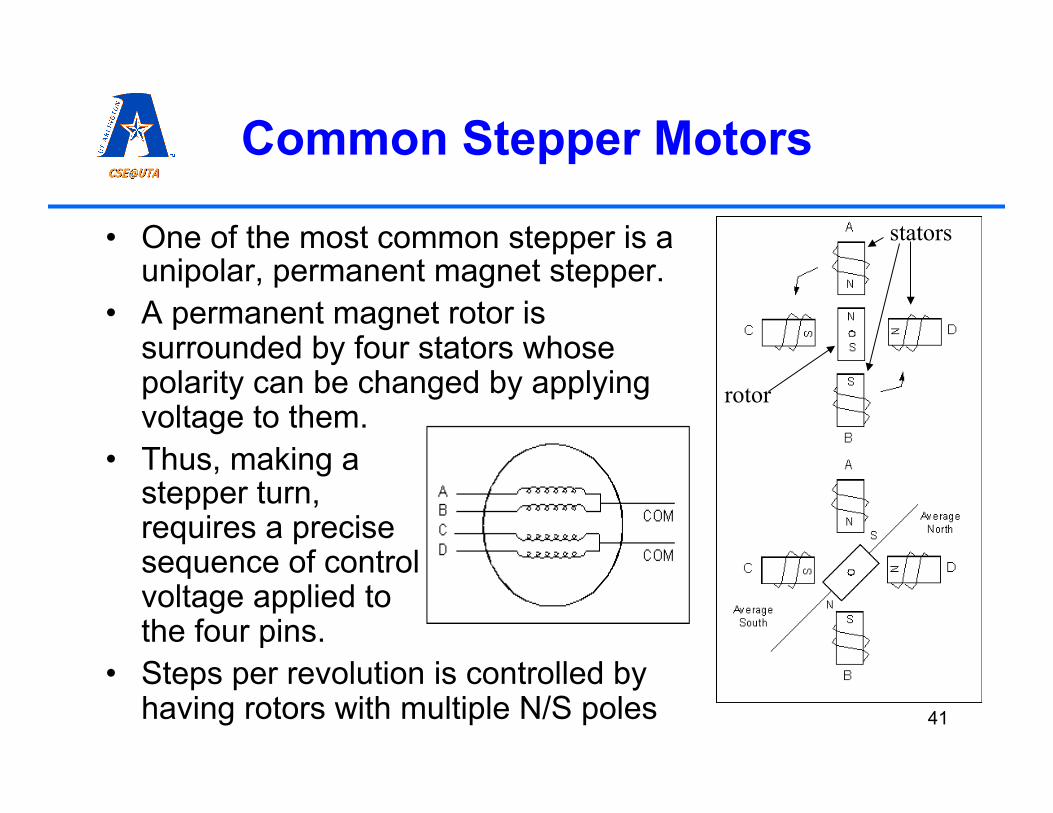
Common Stepper Motors
• One of the most common stepper is a unipolar, permanent magnet stepper.
• A permanent magnet rotor is surrounded by four stators whose polarity can be changed by applying voltage to them.
• Thus, making a stepper turn, requires a precise sequence of control voltage applied to the four pins.
• Steps per revolution is controlled by having rotors with multiple N/S poles
rotor
stators

42
Making Steppers Turn
• Normal stepper sequence:
• Half-step sequence:
Step# A B C D
1 1 0 0 1
2 1 1 0 0
3 0 1 1 0
4 0 0 1 1
cloc
kwis
e
cntr-
cloc
kwis
e
Step# A B C D
1 1 0 0 1
2 1 0 0 0
3 1 1 0 0
4 0 1 0 0
5 0 1 1 0
6 0 0 1 0
7 0 0 1 1
8 0 0 0 1
cloc
kwis
e
cntr-
cloc
kwis
e
Why use one vs. the other? What’s wave drive? (40% more torque, twice the power)

43
Making Steppers Turn
• Connecting steppers to a microcontroller requires back-EMF protection.
Optoisolator provides protection from back-EMF
The motor/2803 should have a separate power source from
the microcontroller
#include <p18F458.h> void main() {
TRISB = 0; while(1) { PORTB=0x06; //0110 MSDelay(100); PORTB=0x0C; //1100 MSDelay(100); PORTB=0x09; //1001 MSDelay(100); PORTB=0x03; //0011 MSDelay(100); }
}

44
Servo Motors
• Servo motors are usually more expensive than DC motors or steppers.
• Servo motors have a precise control for position and are usually not used for complete rotations (although with a little mod they can be – why?).
• Servo motors have a built in mechanism (close control loop) to keep the position they are set to.
• Servo’s usually have three input pins: two for power and one for controlling the angle.
• The control is usually using PWM for position. • Internally, there is an encoder that measures the location of
the shaft, an error signal is produced from the control and current location, and a P, PD, or PID controller is used to reduce this error.
• Length of the pulse dictates location (e.g., 0.6ms = -45 °, 1.5ms = 0 °, 2.4ms = 45 °)

45
Rotary Encoders
• Rotary encoders are rotational sensors (one component of servos), they can provide precise readings of shafts turning.
• Internally they can be mechanical, magnetic (induction) based or optical.
• Optical encoders are usually of high precision, contain encoder wheels. • Encoders can be absolute or incremental • They usually have four to five wires (power+, power-, A, B, 0) • They can be read using timers but will tie up microcontroller; there are
special purpose circuitry to read them, which have parallel or serial interfaces to microcontrollers.

46
Summary
• Timer peripherals can be used to create longer timeouts, to count external events (and act upon), or to create temporal digital signals.
• PWM signals can be used to drive several transducers, some other transducers will output PWM.
• Motor control, and encoder reading are probably two of the most used timer peripheral scenarios.