Embed Size (px)
Citation preview

The Ultimate Factor of Safety for Aircraft and Spacecraft – Its History,
Applications and Misconceptions
Mr. John J. Zipay / NASA – Lyndon B. Johnson Space Center, Houston, TX
Mr. C. Thomas Modlin Jr. / NASA – Lyndon B. Johnson Space Center (retired), Houston, TX
Dr. Curtis E. Larsen / NASA Engineering and Safety Center, Hampton, VA.
ABSTRACT
The ultimate factor of safety (FOSULT) concept used in aircraft and spacecraft has evolved over
many decades. Currently an FOSULT 1.5 is the FAR‐mandated value for aircraft while an FOSULT
of 1.4 has been used in various spacecraft. This paper was motivated by the desire to
concisely explain the origins, proper interpretation and application of the ultimate factor of
safety concept, since the authors have seen throughout their careers many misconceptions
and incorrect applications of this concept. The history of the ultimate factor of safety concept
is briefly summarized, the proper application of the factor of safety in aircraft design,
structural analysis and operations is covered in detail, examples of limit load exceedance in
aircraft and spacecraft are discussed, the evolution of the 1.4 FOSULT for spacecraft is
described and some misconceptions regarding the ultimate factor of safety concept are
addressed. It is hoped that this paper can be a summary resource for engineers to understand
the origin, purpose and proper application of the ultimate factor of safety.
1. Evolution of the Ultimate Factor of Safety Concept
The history of the evolution of the FOSULT has been documented in detail previously. Reference
1 provides the best overall history of the development of the ultimate factor of safety concept.
This paper will not recapitulate that information. However, a brief summary of the evolution of
the ultimate factor of safety concept is needed so that the reader can have the context for the
ensuing discussions.
During the early 1920’s military aircraft were designed to ultimate load conditions using specific
load factors for three flight attitudes: dive recovery initiation, final recovery from a pull‐up and
inverted flight. Civil aircraft used accelerations derived from military testing to specify load
factors based on airplane gross weight and power loading. The science of aerodynamics had
not evolved sufficiently for accurate load predictions so the loads on the wing and empennage
did not consider these effects. There was also no requirement to inspect for potentially
detrimental, permanent airframe deformation if the aircraft experienced loads close to the
design load factor. The “factor of safety” was nominally 2.0 and was often interpreted as a ratio
between ultimate load and maximum probable load.
https://ntrs.nasa.gov/search.jsp?R=20150003482 2020-04-05T20:16:38+00:00Z

The concept of the factor of safety evolved concurrently with the definition of the limit flight
envelope during this period. The formal establishment of an Ultimate Factor of Safety of 1.5
into the U.S. Air Corps requirements occurred in 1930. Initially, the FOSULT applied only to tail
design loads. As more flight data were gathered, the FOSULT became a design criterion. The main
intent of requiring a single value for an FOSULT was that prior to this, airplanes were designed to
different load factors that varied with each type of airplane. The prescription of an FOSULT and
the development of the limit flight envelope concept allowed standardization of strength
criteria across different types of aircraft.
In March of 1934, Revision G of The Handbook of Instructions for Airplane Design (HIAD)
established the 1.5 FOSULT as a formal Air Corps Design Requirement. Around this time the
criteria for no detrimental, permanent deformation at limit load were established. If loads
beyond limit load were experienced by the aircraft and detrimental deformation was
suspected, the aircraft was required to be inspected and repaired before resuming flight
operations.
It was recognized that loads above limit load may occur during flight. These loads might be part
of a statistical distribution (e.g. turbulence), may exceed a selected criterion (e.g., a single
instance of exceeding limit load during the aircraft lifetime or a 3‐sigma distribution and
prescribed confidence interval used for spacecraft design) or may be a unique, stand‐alone
event. It was also observed that airplanes currently flying that were designed to an inferred
FOSULT of 1.5 were flying safely. So much like the rules of baseball, there isn’t a single origin for
the value of 1.5. The value evolved as airplanes were built, flight data was gathered and
experience with higher airspeeds, different aircraft configurations, materials and maneuvers
were acquired.
Today, the Federal Airworthiness Regulation Part 25.303 – Factor of Safety states:
“Unless otherwise specified, a factor of 1.5 must be applied to the prescribed limit loads which
are considered external loads on the structure.”
This is enforced by civilian and military transport authorities and has the force of law within the
United States.
2. The role of the FOSULT in structural design and analysis
Throughout our careers, the authors of this paper have had the unparalleled privilege to be
involved in the structural design of numerous aircraft and spacecraft structures. The design,
development and certification of these structures involved the specification of structural design
and analysis requirements including the ultimate factor of safety. The authors have found that
during this process, many of the engineers tasked with designing or analyzing major structural
components, were not aware of the origins of the FOSULT concept or had misconceptions of
what role the FOSULT plays in aircraft design and analysis. This section is intended to specifically
state what the FOSULT does and does not cover and provide a clear set of rules for its proper
application.
There are three aspects of structural design of aircraft and spacecraft structure that the
Ultimate Factor of Safety is intended to cover:
1. Inadvertent in‐service loads greater than the design limit load.
2. Structural deflections above limit load that could compromise vehicle structural
integrity.
3. As‐built part thickness within tolerance, but less than that assumed in the stress
analysis.
Each of these aspects will be covered in detail throughout the paper.
With any large aircraft or spacecraft structure (such as the Space Shuttle Orbiter), there are
tens of thousands of structural parts, major and minor, that must be analyzed. Simplifying
assumptions are required for the thickness of these parts in order to reduce the analysis
burden. Because of the normal variation within manufacturing tolerance, this can cause some
number of parts that are within drawing tolerance to have lower structural margins than other
similar parts when analyzed for the same loading conditions. One of the functions of the
Ultimate Factor of Safety is to provide some additional structural margin to cover this
anticipated part‐to‐part variation in structural capability.
Some examples from the human spacecraft structural design requirements for the Space
Shuttle, International Space Station (ISS) and Orion Spacecraft are shown below:
• NSTS 07700, Volume X, Book 1 Space Shuttle Flight and Ground Specification 3.2.2.1.5.3 Design Thickness
Stress calculations of structural members, critical for stability, shall use the mean drawing thickness or 1.05 times the minimum drawing thickness, whichever is less. Structural members, critical for strength, shall use the mean drawing thickness or 1.10 times the minimum drawing thickness, whichever is less.
In discussions with senior Orbiter structural engineers, this criteria originated from an internal Douglas Aircraft Standard, one of many that were being reviewed during the Space Shuttle conceptual design phase and has been documented in NASA SP‐8057, “Structural Design Criteria Applicable to a Space Shuttle”.
• SSP 30559 ISS Structural Design and Verification Requirements 3.5.3 MATERIAL DESIGN AND ANALYSIS THICKNESS
The drawing minimum thickness shall be used in stress calculations of pressure vessels, stability critical structure, and single load path structure. The drawing mean/average thickness may be used for stress calculations of all other structure. Actual as–built dimensions may be used in stress calculations when available.
Since the ISS structure would remain on‐orbit for in excess of 15 years, with no ability to inspect or repair and would be exposed to load conditions as on‐orbit operations were developed that could not be anticipated in the design, some slightly more conservative structural analysis criteria were used. This criteria also allows the use of as‐built dimensions in the stress analysis.
• MPCV 70135, MPCV Structural Design and Verification Requirements SDVR0094 Material Thickness for Strength and Stability Margins Flight vehicle structures shall use the lesser of the mean drawing thickness or X times the minimum drawing thickness for structural design and analysis, where X=1.1 for strength critical hardware and X = 1.05 for stability critical hardware. SDVR0049 Material Thickness for Critical Structures Flight vehicle structures shall use the drawing minimum thickness for structural design and analysis of pressure vessels.
These criteria were slightly less conservative than the ISS requirements since the operations and lifetime of the Orion spacecraft were more bounded.
3. Proper use of the Ultimate Factor of Safety
The section discusses the misconceptions regarding what the FOSULT applies to. These misconceptions may originate in the minds of responsible engineers because the origin and application of the Factor of Safety concept is not taught in many aerospace engineering curriculums. The application of the Factor of Safety is often learned on‐the‐job and internal organizational precepts are passed from engineer to engineer. The authors’ experiences have highlighted the need for clarification of what the FOSULT does not cover. While these errors in the application of the FOSULT are not interpreted as irresponsibility on the part of engineers who may not have been taught the boundaries of the FOSULT concept, misconceptions surrounding this topic could have serious consequences in terms of vehicle structural integrity and need to be discussed thoroughly.
• The FOSULT does not cover errors in the structural analysis or structural math modeling.
Competent and correct structural analysis is always required for aerospace vehicles. With the discussion in Sections 1 and 2 as background, it is clear that the FOSULT was not intended to protect for poor structural analysis. In any aerospace design, a prescribed limit load set is used in design, but flight operations could cause these limits to be exceeded. The FOSULT evolved to provide some excess structural capability for the vehicle to withstand these events, without a prohibitive weight increase that would adversely impact its performance. The structural analysis must be correctly performed to determine the structural margins and structural life, provide an efficient design and serve as the benchmark to evaluate load conditions not anticipated during the design. Also, since the concept of FOSULT existed long before the sophisticated computation modeling tools that are available today, it is clear that no portion of the factor of safety can be used to correct for the necessary idealizations and potential errors that can occur in using these tools to analyze a complex structure. The FOSULT preceded digital computers, finite element codes, automesh algorithms, pre‐ and post‐processing software and computer‐aided design. So, while these tools can increase analysis efficiency, allow the design and analysis of complex shapes and render data in easy‐to‐understand plots, these tools are not a substitute for the understanding of load paths, load redistribution and basic analysis methods to ensure structural integrity.
• The FOSULT does not cover poor design practice. A high value of the FOSULT cannot guarantee no failures. Also, a poor design that stems from an inadequate understanding of the loads, use of the wrong materials or bad part geometry or any number of other factors cannot be saved by the FOSULT. Aerospace design is a skill that requires mentorship from experienced engineers and experience designing, fabricating and testing hardware. There are no short cuts to becoming a good designer and structural analysis cannot be relied upon to save an inadequate design.
• The FOSULT does not cover for statistical material property variations. This misconception has cropped up many times in the authors’ experience. Competent, experienced analysts have said that the FOSULT can be used to correct for differences between the material property values that might be obtained from the MMPDS documents, a procurement specification or vendor data that are used in the stress analysis and the actual material properties of the as‐built part. This is incorrect. Most aerospace alloys have material properties already defined to some statistical criteria (“A” or “B” basis, for example). If mechanical properties do not exists for a particular material or particular grain direction, a test program is often undertaken to develop allowables to some statistical basis. Other times, “premium properties”, mechanical properties derived from actual material samples of the as‐built hardware, are used to verify the values used in the structural analysis.

These mechanical properties are completely separate from the definition of the FOSULT. While the statistical basis for the mechanical properties, the definition of the limit loads, the prescribed FOSULT, the process controls through the fabrication and any eccentricities in the applied loading due to the elastic deformation of the structure all combine to determine the load‐carrying capability of a structure, they all interact separately. There is no allocation of part of the FOSULT to account for variation in the mechanical properties of the materials used in the vehicle. While the material properties play a major role in determining the strength, service life, load carrying capability and operating limits of the spacecraft structure, these properties are developed separately to an agreed‐upon statistical basis commensurate with the cost and risk posture of the vehicle program and then an FOSULT is applied on top of these properties in the stress analysis.
• The FOSULT does not cover process escapes. Another surprisingly common misconception is that the FOSULT can be used to compensate for process escapes during manufacturing. For example, some engineers believe that the additional structural capability provided by the FOSULT can overcome MRB actions such as out‐of‐tolerance parts, misdrilled holes, fasteners or materials different than those specified on the drawings or even missing components. If the additional capability provided by the FOSULT happens to prevent structural failure in these situations, it is merely a serendipitous occurrence. It is assumed that the aircraft or spacecraft is built to print or with any discrepancies dispositioned as not affecting fit, form or function. There is no substitute for a rigorous quality assurance program in aerospace vehicle development.
4. How the FOSULT protects structural integrity when limit loads are exceeded. The 1.5 FOSULT is applied to external ground and flight loads. There are other factors of safety
specified for pressurized lines and pressurized components, for example, as well as
supplemental factors such as casting or fitting factors. The rationale for these other factors can
be researched separately. The intent of specifying a 1.5 FOSULT is so that each vehicle has a
fixed, single factor of safety requirement and that the verified structural capability of each copy
of each vehicle is consistent.
Exceedances of limit load conditions occur in commercial aircraft, military aircraft and
spacecraft such as the Apollo Command Module, Space Shuttle Orbiter and the International
Space Station (ISS). The FOSULT provides a certain level of additional capability to maintain
structural integrity for limit load exceedances. As the FOSULT is reduced below 1.5, there will be
an increasing number of load cases beyond limit load that will not be covered. Reducing the
factor of safety has quantitative impacts on structural failure probability and operational
flexibility to respond to changes in external loading.

While very rare, in‐flight break‐ups of commercial airliners due to limit load exceedances have
occurred. Below is a partial list of such incidences.
• 2/12/63 ‐ Northwest Orient Airlines Flight 705, a Boeing 720, breaks up in turbulence associated with a severe thunderstorm and crashes into the Everglades.
• 3/5/66 – BOAC Flight 911, a Boeing 707, "The aircraft suddenly encountered abnormally severe turbulence over Gotemba City which imposed a gust load considerably in excess of the design limit.“
• 8/6/66– All 42 on board are killed when Braniff Flight 250, a BAC One‐Eleven, flies into an active squall line and breaks apart in mid‐air near Falls City, Nebraska.
• 3/5/68 ‐ Braniff Flight 352 , a Lockheed L‐188A Super Electra en route from Houston, Texas to Dallas, breaks up in mid‐air in a thunderstorm and crashes near Dawson, Texas.
• 5/7/81 – Austral Líneas Aéreas Flight 901, a BAC One‐Eleven, crashes near Aeroparque Jorge Newbery after losing control in a thunderstorm, killing all 31 on board.
• 11/6/81 ‐ October 6 – NLM CityHopper Flight 431, a Fokker F28 Fellowship, is destroyed in flight by a tornado near Rotterdam, killing all 17 people on board.
• 5/26/91 – Lauda Air Flight 004, a Boeing 767, disintegrates in mid‐air over Uthai Thani Province and Suphan Buri Province, Thailand, killing all 223 people on board. A thrust reverser had accidentally deployed in flight, causing the disaster. It is the first fatal crash of a Boeing 767.
There are also several dramatic instances of commercial airliners exposed to over‐limit
conditions where the aircraft survived.
• On November 9, 1963, a DC‐8 (tail number N840TW) operating for Eastern Airlines took off from Houston, TX. At around 3:02 p.m. local time, while the plane was climbing through 19,000 feet, it encountered turbulence and hail associated with a thunderstorm. Airspeed reportedly dropped to zero momentarily, prompting the crew to push the nose down. This turbulence caused the aircraft to dive, resulting in the separation of the #3 engine and damage to the wing. (Anomalies in the Pitch Trim Compensator contributed to the loss of control.)

The crew recovered from the dive at 5,000 feet by using reverse thrust in‐flight. The airplane performed an emergency landing at Barksdale Air Force Base in Louisiana. (Note: A similar issue caused the total loss of a DC‐8 on 11/29/1963.)
• On April 4, 1979, a Boeing 727‐31 (tail number N840TW) operating as TWA Flight 841
took off from John F. Kennedy International Airport, New York City, en route to Minneapolis‐Saint Paul International Airport in Minneapolis, Minnesota. At around 9:48 p. m. local time, over Saginaw, Michigan, while the plane was cruising at 39,000 feet (11,887 m) and Mach 0.816, it began a sharp roll to the right. The roll continued despite the corrective measures taken by the autopilot & the human pilot. The aircraft went into a spiral dive, losing about 34,000 feet (10,363 m) in 63 seconds. During the course of the dive, the plane rolled through 360 degrees twice, and crossed the Mach limit for the 727 airframe. Control was regained at about 5,000 feet (1,524 m) after the first officer, with the captain in agreement, extended the landing gear in an attempt to slow the aircraft,
and following the loss of the #7 slat from right wing.
The plane suffered substantial structural damage, but made an emergency landing at Detroit Metropolitan Airport, Michigan, at 10:31 p. m. No fatalities occurred among the 82 passengers and seven crew members. Eight passengers reported minor injuries relating to high G forces.
• On 2/19/85, China Airlines Flight 006, a Boeing 747SP‐09 was 350 miles northwest of
San Francisco, cruising at an altitude of 41,000 ft. when the No. 4 engine stalled at a low
thrust setting and flamed out. After the flameout, the captain instructed the flight
engineer to attempt to restart the engine, with the autopilot still engaged and the Bleed
air on. That was contrary to the flight manual procedure, which required the plane to be
below 30,000 feet, before attempting to restart a flamed out engine.
The attempt failed. The airspeed continued to decrease, while the autopilot rolled the
control wheel to the maximum left limit of 23 degrees. By the time the captain
disconnected the autopilot, the plane had rolled over 60 degrees to the right and the
nose had begun to drop. To counteract the asymmetrical forces created by the loss of
thrust from the No. 4 engine, it was essential for the pilot to manually push on the left
rudder. However, the captain failed to use any rudder inputs at all, before or after
disconnecting the autopilot.
As the plane descended through clouds, the captain's attention was drawn to the
artificial horizon which displayed excessive bank and pitch. Because such an attitude is
highly irregular, the crew incorrectly assumed the indicators to be faulty. Without any
visual references (due to the clouds) and having rejected the information from the ADIs,
the crew became spatially disoriented. The plane entered a steep dive at a high bank
angle. The altitude decreased 10,000 ft. within only 20 seconds, a vertical descent
averaging 30,000 feet per minute The crew and passengers experienced g‐forces
reaching as much as 5g.
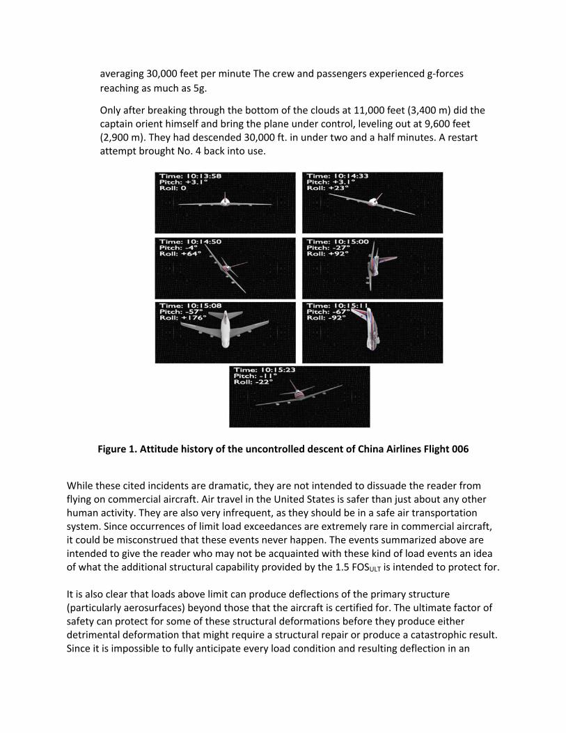
Only after breaking through the bottom of the clouds at 11,000 feet (3,400 m) did the captain orient himself and bring the plane under control, leveling out at 9,600 feet (2,900 m). They had descended 30,000 ft. in under two and a half minutes. A restart attempt brought No. 4 back into use.
Figure 1. Attitude history of the uncontrolled descent of China Airlines Flight 006
While these cited incidents are dramatic, they are not intended to dissuade the reader from flying on commercial aircraft. Air travel in the United States is safer than just about any other human activity. They are also very infrequent, as they should be in a safe air transportation system. Since occurrences of limit load exceedances are extremely rare in commercial aircraft, it could be misconstrued that these events never happen. The events summarized above are intended to give the reader who may not be acquainted with these kind of load events an idea of what the additional structural capability provided by the 1.5 FOSULT is intended to protect for. It is also clear that loads above limit can produce deflections of the primary structure (particularly aerosurfaces) beyond those that the aircraft is certified for. The ultimate factor of safety can protect for some of these structural deformations before they produce either detrimental deformation that might require a structural repair or produce a catastrophic result. Since it is impossible to fully anticipate every load condition and resulting deflection in an

aerospace vehicle’s operational life, the ultimate factor of safety provides additional structural capability for unanticipated excursions beyond limit load during flight operations.
5. The 1.4 Ultimate Factor of Safety for Spacecraft Many questions have arisen as to how the 1.4 factor of safety has been adopted for spaceflight hardware. NASA‐STD‐5001B, “Structural Design and Test Factors of Safety for Spaceflight Hardware”, Table 1 states:
There hasn’t been a summary history written about the origin and application of the 1.4 FOSULT for spacecraft. This section is an attempt to provide the background behind the origin of the 1.4 FOSULT for spacecraft. The 1.4 Ultimate Factor of Safety originated within The Aircraft Laboratory, Wright Air Development Center (now Wright‐Patterson Air Force Base). A study related to the X‐20 Dyna‐Soar program evaluated the applicability of the 1.5 FOSULT for large separable boosters for manned space vehicles. To maximize structural efficiency, design working stresses were brought closer to material yield stresses. Because of the uncertainty related to the design of large integral pressure vessels subjected to flight loads and temperatures, a 1.1 Factor of Safety on yield (FOS YLD) was chosen in combination with a 1.4 FOSULT.
The 1.4 FOSULT was intended specifically for the X‐20 booster. It was not intended to be used without the 1.1 FOS YLD. However, the 1.4 Ultimate Factor of Safety with a 1.0 yield factor of safety has been accepted throughout NASA spaceflight programs. The primary objective for reducing the factor of safety was to save weight. However, reducing the factor of safety does have implications for structural reliability. Therefore, other safeguards such as day‐of‐launch software updates to control ascent loads, flight restrictions on entry to control aerodynamic loads and instrumentation to correlate structural math models with flight data were developed to reduce the probability of exceeding limit load commensurate with the reduction of the FOS ULT from 1.5 to 1.4. In the Early 1990’s, the NASA Engineering Management Council empowered a group of structural engineers from across the Agency to develop the minimum factor of safety criterion

for launch vehicles and spacecraft. The group included representatives from both the human and robotic exploration programs.
The result was the baseline version of NASA‐STD‐5001, Structural Design and Test Factors of Safety for Spaceflight Hardware, in 1996. The requirements delineated in this standard are based on the consensus judgment of a working group of structural engineers from all the NASA Centers. This activity was prompted by concerns expressed by industry and NASA program management that practices and requirements in this area varied widely between Centers, making the verification of structural adequacy difficult for projects involving multiple Centers, resulting in increased costs to verify identical hardware under different criteria. Subsequent revisions of NASA‐STD‐5001 have added factors for preloaded joints, softgoods, windows, pressure vessels and other pressurized components. An interesting finding from the effort to develop NASA‐STD‐5001 was that structural engineers from both the human and robotic spacecraft programs agreed on 1.4 as the minimum FOSULT for metallic structures. The structural engineers present did not feel that a different FOSULT was required for robotic vs. crewed spacecraft since lowering the FOSULT below 1.4 did not save a great deal of weight for the increased risk. The reduction of weight vs. the increased risk of reducing the FOSULT below 1.4 is covered in the next section. There have been instances of limit load exceedances in human spaceflight programs. Fortunately these did not lead to loss of crew. Since these also are very rare, they are presented so that the reader understands that even under the most controlled conditions, exceedances of limit load do occur for spacecraft structure.
• Apollo 6 (Vehicle 502) and Apollo 13 POGO instabilities. o For the unmanned test flight of Vehicle 502, Engines #2 and #3 shut down on the
S‐II stage prematurely and portions of the Spacecraft Lunar Module Adapter (SLA) failed.
o During Apollo 13, the center engine of the S‐II stage shut down prematurely due
to POGO.
• Apollo 15 loss of one parachute during landed exposed the structure to higher than anticipated impact loads due to the heavier Command Module weight. (10 m/s vs. 8.5 m/s)
• STS‐1: SRB ignition overpressure signature was at a higher frequency than expected. This frequency tuned with the Orbiter first bending mode. One Forward RCS strut was found to be buckled during post‐flight inspection. Sound suppression water was used for subsequent missions and the strut was replaced.
• STS‐3: I‐load designed into ascent trajectory for higher sideslip angle. Between the last

balloon wind data and the launch, the wind changed direction resulting in a slight overload on one spot of the wing. Inspection revealed no damage.
• 1/14/09 – Excessive vibrations were input into the ISS Structure due to an anomalous
reboost firing of the Service Module thrusters. (Can be seen at: http://www.youtube.com/watch?v=ENNq69499tA)
6. Misconceptions regarding the Ultimate Factor of Safety
• The 2.0 “No‐Test” Factor of Safety for Spacecraft
It is often impossible or impractical to test every piece of load‐carrying structure on a spacecraft. This has given rise to the question of what FOSULT should be used for untested load‐carrying structure. Recently, it came to the attention of the authors of this paper that the use of an FOSULT of 2.0 was being used as a justification to support not testing primary or secondary structure. This is not acceptable practice. A high factor of safety does not guarantee no failures. It also cannot overcome poor design practice, ineffective quality control, an incorrect understanding of load paths, incorrect structural analysis or brittle material failures. This section is an attempt to determine, based on spacecraft history, how the “No‐Test” FOSULT of 2.0 slipped into structural analysis practice for spacecraft.
• Based on research it was determined that Skylab used a FOSYLD of 2.0 and an FOSULT of 3.0 for its untested launch shroud structure.
• An FOSYLD of 1.25 on Yield and an FOSULT of 2.0 was used for the untested structures of
the Long Duration Exposure Facility (LDEF) experiments, the Shuttle Solid Rocket Booster (SRB) Systems Tunnel, the SRB heater cover and cable channel, the Tethered Satellite System and the metallic components of the Hubble Space Telescope.
• An FOSULT of 1.2 was used on the Space Shuttle External Tank for the quasi‐static portion of the applied loads.
• Very early in the Space Shuttle Program, Air Force payloads that had already been tested
to ultimate loads required certain modifications to fly as a payload in the Orbiter. It was agreed that an FOSULT of 2.0 by analysis could be used to certify these modifications to the already test‐verified structures.
• NASA/Goddard Space Flight Center recommends a FOSYLD of 2.0 and an FOSULT of 2.6 for
untested structures.
• SSP 30559, the Structural Design and Verification Requirements for the ISS, permitted the use of an FOSYLD of 1.25 and an FOSULT of 2.0 for untested ISS Structures that were designed primarily to withstand on‐orbit loads.

• Shuttle Payload Verification Requirements, NSTS 14046, did not have a factor of safety
defined for verification of untested payload structures.
The FOSULT of 2.0 on propagated through the Shuttle and ISS payload design communities and often became a de‐facto rule for analyzing untested structures. CxP 70135, the Structural Design and Verification Requirements for the Constellation Program (that later were flowed to the Orion Program) included a section which stated that there is no such thing as an “analysis‐only” Factor of Safety for spacecraft structures: The determination of whether to certify a structure by analysis and what Factor of Safety to use must be performed on a case‐by‐case basis. (ref.: NASA‐STD‐5001 and FAR Part 23 and Part 25 criteria). So, there is no such thing as an “analysis‐only” factor of safety that obviates the need for structural testing.
• The 1.5 Ultimate Factor of Safety was derived in the early days of aviation by ratioing the
ultimate and yield strengths of aluminum.
The 1.5 Ultimate Factor of Safety for tail design loads had already been adopted when the Air Corps began using 2024 Aluminum (designated 24ST at the time). In the early 1930’s, 4130 steel had a ratio of ultimate strength‐to‐yield strength of 1.2 and was widely used in aircraft at the time. Through the 1920’s and into the 1930’s, 1025 steel was widely used. Other materials used at the time in airframes did not have a 1.5 ratio of ultimate strength‐to‐yield strength. The 1.5 Ultimate Factor of Safety was supported by, but was not the result of, the 24ST aluminum alloy that was coming into use. A table of typical material used in early aircraft clearly shows that the 1.5 FOSULT was not related to the mechanical properties of Aluminum. Table 2. – Ultimate strength /Yield Strength ratio of structural materials used in early aircraft Material Ult. Str. (psi) Yield Str. (psi) Ratio Spruce – Bending 9400 6200 1.52 Spruce – Compression 5000 4000 1.25 1025 Steel 55000 36000 1.53 X‐4130 Steel 95000 75000 1.27 (Plate & Tube less than 0.188” thk.) X‐4130 Steel 90000 70000 1.29 (Plate & Tube greater than 0.188” thk.) 17ST Sheet & Plate 55000 32000 1.72 17ST Clad Sheet & Plate 50000 27000 1.85 17SRT Sheet & Plate 55000 42000 1.31 17SRT Clad Sheet & Plate 50000 37000 1.35 24ST Sheet 62000 40000 1.55 24ST Clad Sheet 56000 37000 1.51
24SRT Sheet 65000 50000 1.30 24SRT Clad Sheet 58000 46000 1.26 Ref: ANC‐5, Strength of Aircraft Elements – October, 1940
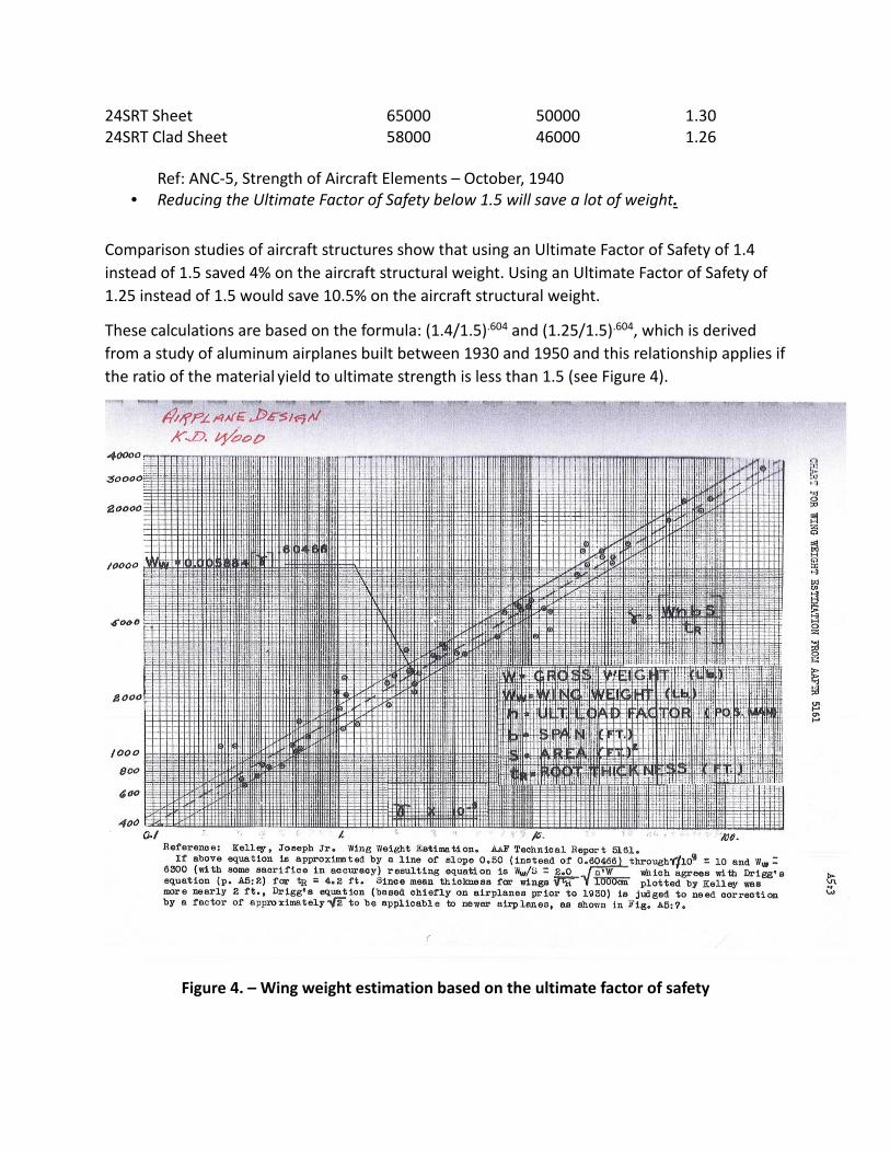
• Reducing the Ultimate Factor of Safety below 1.5 will save a lot of weight.
Comparison studies of aircraft structures show that using an Ultimate Factor of Safety of 1.4
instead of 1.5 saved 4% on the aircraft structural weight. Using an Ultimate Factor of Safety of
1.25 instead of 1.5 would save 10.5% on the aircraft structural weight.
These calculations are based on the formula: (1.4/1.5).604 and (1.25/1.5).604, which is derived
from a study of aluminum airplanes built between 1930 and 1950 and this relationship applies if
the ratio of the material yield to ultimate strength is less than 1.5 (see Figure 4).
Figure 4. – Wing weight estimation based on the ultimate factor of safety

The impacts of lowering the Ultimate Factor of Safety are significant. For example, the number
of load cases beyond limit that the structure cannot withstand will increase. Re‐use of the
structure after a limit load exceedance could be problematic if detrimental deformation occurs.
Repairs may be required before returning the structure to service. The structural reliability of
the airframe when subjected to loads greater than limit is reduced. The structural life of the
airframe is affected since it will be subjected to higher nominal operating stresses.
There have been many attempts to relate structural reliability to the value of the Ultimate
Factor of Safety. A simple method is provided below as an illustration of the effect of lowering
or raising the value of FOSULT. Now there are many other factors involved in structural reliability,
so this chart cannot be taken as the only indicator, but it is useful in understanding the
sensitivity of structural reliability with respect to the value of the Ultimate Factor of Safety.
Figure 3 is intended as a simple example under these assumptions:
1) Loads are assumed to be normally distributed, so the use of the standard normal distribution
tables to evaluate probability is valid.
2) The Limit load is n‐sigma of the load distribution.
3) The Ultimate load = LL x FOSULT.
4) The strength of the airframe is distributed as a Dirac delta function at the ultimate load. So,
no lower tail or probability of any parts having strength less than ultimate load is assumed. This
is perfect screening inspection and acceptance. Also no upper strength tail is assumed, so zero‐
margin design and manufacture is assumed.
With these assumptions, the probability of a load event exceeding the ultimate strength of the
airframe is simply looked up from standard normal distribution table or function at FOSULT x n‐
sigma. Under these conditions, one could argue that this is an upper bound on the unreliability,
so a lower bound on the structural reliability.

Figure 5. – Structural reliability as a function of both ultimate factor of safety and limit load
probability distribution There are many more effective strategies to reduce weight than lowering the Ultimate Factor of
Safety. The loads and structural criteria can be reviewed for unnecessary conservatism. For
example, the use of arbitrary Uncertainty Factors should be discontinued as a general practice.
This will put weight in a structural design up front that is almost impossible to remove. It is
always simpler to add weight to a structure than remove it. For example, the weight scrub
activities on Apollo were budgeted at $10,000 / lb. For Shuttle, this number rose to $50,000 /lb.
Weight scrubs due to over‐conservatism in structural design are difficult and expensive and
should be avoided by prudent engineering design and weight management upfront.
Tightening the manufacturing tolerances on parts can reduce the amount of material in the
structure. The judicious use of structural optimization routines as analytical tools developed
through the enormous computational resources that are available can be invaluable in reducing
structural weight. Structural materials can be hand‐selected for “premium” properties as

opposed to the more conservative “A” – basis or “B”‐basis material allowables to provide
greater ultimate strength. Finally, a review of the driving load cases can be performed to
determine if functional redundancies or operational controls can be used to eliminate or reduce
the applied loads.
Conclusions
This paper was motivated by the perceived need to develop a consistent interpretation of the
Factor of Safety throughout the aerospace structural engineering community. The paper is
intended to guide discussions on the meaning and proper use of the factor of safety during
development of aerospace structure. This paper could not have been written without the
scholarly wisdom and encyclopedic knowledge of Mr. C. Thomas Modlin, NASA‐JSC Chief
Engineer and Structural Mechanics Branch Chief (Emeritus) and Dr. Curtis E. Larsen, Loads and
Dynamics Technical Expert at the NASA Engineering and Science Center. It is hoped that this
paper can be used as source material in the future when the origin, purpose and proper
application of the ultimate factor of safety for aircraft and spacecraft are discussed.
References
1. “Factors of Safety – USAF Design Practice” – George E. Muller, Clement J. Schmid – Air
Force Flight Dynamics Laboratory, Wright –Patterson Air Force Base, Ohio – Published as
part of AGARD Report #661 – Factors of Safety – Historical Development, State of the
Art and Future Outlook.