Embed Size (px)
Citation preview
ARCH 614 Note Set 12.1 S2014abn
3
The tributary area is a loaded area that contributes to the load on the
member supporting that area, ex. the area from the center between two
beams to the center of the next two beams for the full span is the load
on the center beam. It can also be called the load periphery.
The tributary load on the member is found by concentrating (or
consolidating) the load into the center.
)()( widthtributaryxarea
loadw
where:
w = distributed load in units of load/length
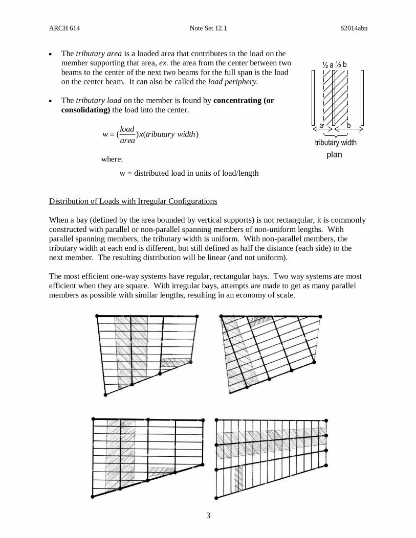
Distribution of Loads with Irregular Configurations
When a bay (defined by the area bounded by vertical supports) is not rectangular, it is commonly
constructed with parallel or non-parallel spanning members of non-uniform lengths. With
parallel spanning members, the tributary width is uniform. With non-parallel members, the
tributary width at each end is different, but still defined as half the distance (each side) to the
next member. The resulting distribution will be linear (and not uniform).
The most efficient one-way systems have regular, rectangular bays. Two way systems are most
efficient when they are square. With irregular bays, attempts are made to get as many parallel
members as possible with similar lengths, resulting in an economy of scale.
plan
tributary width
½ a ½ b
b a

ARCH 614 Note Set 12.1 S2014abn
4
Distribution of Loads on Edge Supported Slabs
Distributed loads on two-way slabs (i.e. not one-way like beams) do not have obvious tributary
“widths”. The distribution is modeled using a 45 degree tributary “boundary” in addition to the
tributary boundary that is half way between supporting elements, in this case, edge beams.
The tributary distribution from the area
loads result in a trapezoidal distribution.
Self weight will be a uniform distributed
load, and will also have to be included for
design of beam AB.
Openings in Floor/Roof Plans
Openings in a horizontal system usually are framed on all sides. This provides for stiffness and
limiting the deflection. The edge beams may not be supporting the flooring, however, so care
needs to be taken to determine if an opening edge beam must support tributary area, or just itself.
Any edge beam supporting a load has load on only one side to the next supporting element.
Beams Supported by Other Beams
Joists are commenly supported by beams with beam
hangers. The reaction at the support is transferred to
the beam as a single force. A beam, in turn, can be
supported by a larger beam or girder, and the reaction
from this beam having a uniform distributed self
weight, and the forces, will be an action on the girder.

ARCH 614 Note Set 12.1 S2014abn
5
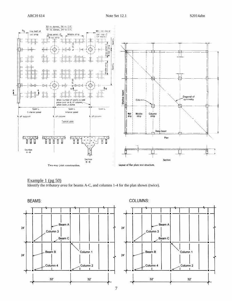
Framing Plans
Framing plans are diagrams representing the placement and organization of structural members.
Until the final architecture has been determined, framing plans are often drawn freehand with
respect to the floor plans, and quite often use the formal conventions for structural construction
drawings.
Parts of the building are identified by letter symbols:
B – Beams F – Footings L – Lintels U – Stirrups
C – Columns G – Girders S – Slabs W – Walls
D – Dowels J – Joists T – Ties
Other parts are represented with lines (beams and joists), dots, squares, rectangles or wide-flange
shapes for columns. Column and footing locations in structural drawings are referred to by
letters and numbers, with vertical lines at column centers given letters – A, B, C, etc., and
horizontal lines at columns given numbers – 1, 2, 3, etc. The designation do may be used to
show like members (like ditto).
Spanning direction of decking or reinforcement

ARCH 614 Note Set 12.1 S2014abn
6
Breaks in the lines are commonly used to indicate the end of a beam that is supported by another
member, such as a girder or column. Beams can span over a support (as a continuous beam) and
therefore, there is no break shown at the column.
Joists can span over a supporting beam, and the lines will
cross. (Looking for the ends of the crossing members give
information about which is below and which is above.)
Concrete systems often have slabs, ribs or drop panels or strips, which aren’t easily represented
by centerlines, so hidden lines represent the edges. Commonly isolated “patches” of repeated
geometry are used for brevity.
ARCH 614 Note Set 12.1 S2014abn
7
Example 1 (pg 50) Identify the tributary area for beams A-C, and columns 1-4 for the plan shown (twice).
BEAMS: COLUMNS: