Embed Size (px)
Citation preview

University of RichmondUR Scholarship Repository
Master's Theses Student Research
1968
The theory and development of a dyeing machineemploying the rotary pendulumAshley Paul Smith
Follow this and additional works at: http://scholarship.richmond.edu/masters-theses
Part of the Physics Commons
This Thesis is brought to you for free and open access by the Student Research at UR Scholarship Repository. It has been accepted for inclusion inMaster's Theses by an authorized administrator of UR Scholarship Repository. For more information, please [email protected].
Recommended CitationSmith, Ashley Paul, "The theory and development of a dyeing machine employing the rotary pendulum" (1968). Master's Theses. Paper1053.
THE THEORY AND DEVELOPMENT OF A DYEING MACHINE EMPLOYING THE
ROTARY PENDULUM
BY
ASHLEY PAUL SMITH
A THESIS SUBMITTED TO THE GRADUATE FACULTY
OF THE UNIVERSITY OF RICHMOND IN CANDIDACY
FOR THE DEGREE OF MASTER OF SCIENCE IN PHYSICS
AUGUST, 1968
LI OR.lH~Y
· UNIVC::RS r 1· ,. o ;:- R lCHMONC \.'lRGlNIA

ABSTRACT
A review of dyeing methods for carpet is made with the
objective that the requirements of a new machine could be
formulated. The proposal for a new machin e i s made in the
light of the above review using a pendulum as the basic com
ponent. A theory is developed for the motion of the pendulum
which is mounted on a rotating disc , and the experimental
work built on theory is outlined. A prototype machine based
on the r otary pendulum mechanism was used to dye impregnate
carpet.

-
TABLE OF CONTENTS
Introduction
Theory ·
S~lution of ~quation of Motion
Machine Design and Testing
Conclusions
Glossary of Textile Terms
·References
Bibliography
Vita
Acknowledgements
U CR/\!~Y
UNl\/~RSIT Y C l- f"\ IC HMONC V l flGl;-..J lt\
ii
1
14
20
29
40
42
44
46
.f ie;ure
1.
2 .
3.
4 .
5.
LIST' OF FIGURES
Production flow charts of package~ skein, piece, a nd impact dyeing.
Diagram of a dyebeck unit .
Diagram of a beam dyei ng un i t. Cit
Nip conditions fo r impact dye expression .
Fabric dye i mpregnated by roller padder.
6 . Effect of lump on rigid r ollers and correcti v·e measures.
7.
8.
9.
10.
11 .
12.
13 .
14 .
15.
16.
17 .
18.
19.
Pictorial drawing of rotary pendulum .
Forces on rotary pendulum in flight.
Dimension relationship of rotary pendulum system .
Equations and parameters used to determine initial .v alues of rotary pendulum systen .
Imagina ry analog plot for guideline to in terpret actual plots~
Graph of hub radius versus percentage of K for radial impact .
Graph showing pendulum response insensitive to speed of rotation .
Run 36 of analog plots .
Hub tessellation.
Illustration of obtaining information for escapement openings .
Layout of rotary pendulum assembly.
Illustration of six pendulum arrangement.
Flight of an icpacter at v a r ious escapement openings.
iii
3
4
6
8
9
11
15
18
21
23
25
27
28
· 33
36
37
38
39

I • . INTRODUCTION
The object of the investigation reported here is the de
velopment of a rotary pendulum form of impacting device for
the application of dye liquor to fabrics, particularly carpet
ing.
The re a sons for undertaking the development of a differ
ent desi gn of dyeing macnine are centered around the increas
ing demands of the textile dyeing and finishing industries
for more capabilities in industrial equipment. These desired
capabilities are the applicability of equipment to non-uniform
surfaces and to all fibers, the adaptability of rn~chincs to
shade changing with minimum down time (less than 10 minutes) ,
the reduction of water consunption per square yard of fabric,
an increase in the speed of dyeing (more than 5 running yards
per minute), and a reduction of costs per square yard of dyed
material .
Currently, the carpet dyeing processes used in the tex
tile industry are stock, skein, package, and piece dyeing.
(See Glossary of Textile Terms, page 42, for definitions of
these and other terns.) Production flow charts of dyeing

2.
1 processes are shown in Figure 1 . Stock dyeing is not shown;
howeve~, it is the most lengthy of the p~ocesses for the car-
pet manufacturer.
Piece dyeing has important economies over stock, skein, ·2
and package dyeing and also has the following capabilities:
l. Custom dyeing in a complete range of shades from a
single greige inventory;
2. Greater flexibility in introducing new shades; 3
3. More rapid deliveries of carpet to consumers •
Thus, the proposed new machine ideally should employ a piece
dyeing process . A brief review of the existing piece dyeing
processes used on carpets, including their good end bad points ,
is included to point up the need for a new design. Beck and
.beam dyeing, two existing piece-dyeing processes, will be
reviewed in addition to the roller padding process which is
being developed actively in Europe. These processes were
studied in order to formulate operating parameters for the
proposed new process~
In the beck dyeing process the greige carpet, approxi -
mately 150 running yards, is fed into the dye bath over a
reel. The ends of the carpet are st~tched together to form a
continuous length which is immersed repeatedly into the dye 4
liquor . Figure 2 is a diagram of a dyebeck unit.
The primary advantage of the beck dyeing process is the
consistency of uniform results from lot to lot, with economic 5
reasons being of secondary _i mportance . The negative features

i · ?~~~·ic;E · ~~~N..~J l .... YARN AS RECEiVED "' l '- -or--, ... ---·"""'--, ... - -·"· ---. ..J . l ._ .... ... .. -.
· ! SKEIN t : ! ----···---'I ·-
BULK
. _ .. ··:~·::-~··~·- :~·~ ~1 ! :- . ~ . ... . -.- ... - .......
• ·· - . .... __ __; r · I
. 1 DYE, ... . . ' .. .... ; I
PACK ACE
··-·--.. ~-- -·-- ~·--____ ) . .. . ........ EXTRACT .• - ---· :
: .. ~--~~~=-.] . ;~ :-·-~·-.'. : DRY i ... - ... - .. -. ·· -· · ·-· · .. · .. ~ · . - . . -- ----. j BACKWIND j ····· --~-·- --· -'" ' i .... -
:. ~~ - ~-~-~--:.-.~ .-~N ; ~~- - .... ... . ... ! . . --- -- ·-··-"'
l~YENTORY
COLOR A COLOR B COLOR C
· · ETC. (a dozen 9r more colors fOr l ine}
··- ·- - · · · - - --- p
CREEL ...... ----·---·-- ---- -...-···--- i 1..---- .. -
. 1 . TUFT I ______ ... ---- - -- - , ... - -·- .. . ,. .. - -·--··-' L --
1 FINISH i .. ---------.. ] r-·---: .. ··--·-· r----- ----· " ·- .. -------~~~- .. ....... --i
. I ........ - SKEIN DYEING I ~~J . , :.~~·--:-:-:-: L.. YARN As R~=~~vep _ (
.. ..... .... .. _ ... ... J ..... -- ... . - .. I . SKEIN - ·· ~ r ---~ " .• _ .... __ _ .... _ .. ..i . . . .... .... .... ••
I_ DY~_ .. ___ J .
I _ ........ .... EXTRACT . I . ~----.
• -· .............. . J ' .
r DRY ,_ ,--· -·-- ·
' r·· --·_ .. BACK WIND · · · · ·
·~--~.-:-~ . · ·-· ---a>NE
·----- ' INVENTORY
COLOR A COLOR B I COLOR c i .
! ETC. ; I( a dozen or more colors for l ine) ; ~-~-:.=::~-::; .- : :..:..:~==~:··· .~·
~ CREEL 1 _-.... ::::.:..-.==::i - .. =:.-==:-~: I TUFT ' ..,_ .. _ ... -··--- -
1 .. .. . . ..... "' .. -·-- -·-·· • I FINISH ! !_-·-:-:-.::..-.::·:::-.s1 :.:=:.:::::-.::.-.1
SHIP
~ . PIECE DYEING i l .. . .. .. ... .
----··-···· .. --· ··- ·-- - ...l
l;. YA~·N ~-~ REf::~~~~~=-j ' . : ....... ...... - • " • .. .. . ..... .. f
l . c~eE:__ ___ _ l 1· .... _,, . ' ........ ..... '
-=-.~:.:·-.:-~uF~ · ·- · ~-. _I
\
INVENTORY I (one item for each pattem) ., j
--·- ·- .. , --------· OYE .......... .. . j
I .. . .. .... I · - .. - ·-- - ---
i . EXTRACT 1 _ _ __ .. _ , ;----
1· ......... -..... DRY-- --~ ... - -)
I,._. • .. -----'
{--. - .- .1 L--·- -- . l FINISH I
J r----
L __ .~· SHI~-·- .. -·==!
IMPACT DYEING I r.
L. .. .. YARN A.is RECEIVED ~ j ----·-1 - ···-----
. .. . . ·' ... ... -· . __ ..
I CREEL - -··---
!.. . .. " • ••• • • • '... • '. . I
TUFT
I ·-·-· ~'- -~ - ----------· INVENTORY , :-···------"'
.. --: ·;-····· .DYE . ;· .. ,,_ ... - ... ,
.... ...---·- -' . ' . .... --- ----. . ......... . . .. , f_ STE~~ _j
... . - ... - . ·--- ... i l ... ·- ·- ·-·--!__ FINISH __ . ___ I I ·.-~~- --·--·SHIP '--------·
.. .. _ ..... ____ _
.FIGURE
~

4 •
FIGURE 2
REEL
CARPET ·, ..
S UPPLEM ENTA RY ~J_E_AM _l:.l __ N_E ______ -· ~©--
........ ' -·-·-
D.YEBECK U NJT

5.
are the slowness of the process (for medium shades an average
dyeing · time of 4 hours per lot of 250 square yards}, large
water consumption (approximate ly 1,500 gallons per lot), and
prolonged exposure of fibers to near boiling temperatures
vhich tend to vea~en the yarn. Temperature variations of the
dye bath (a difference of 3° to 4°F. from point to point) can
adversely affect the finish or texture of the carpet by pro-
ducing pile distortion and variation o f shading across the 6,7
carpet vidth
In beam dyeine, the greige carpet, vound on a special
perforated beam, is placed in a dye machine . The dye liquor
is pumped through the carpet from the center of the beam out-
ward, and then from the .outside carpet surface to the center 8
of the beam · (Figure 3) . Beam dyeing is especially useful
for particularly textured carpet, such as cut-pile and frieze
style, where loss of twist is not as pronounced as in beck
dyeing. Positive results obtained when beam dyeing carpet~
are as follovs:
l. Minimum handling of carpet;
2 . tess mending involved as carpet is stationary;
3. Virtual elimination of side-to-side shading;
4. Considerable savings in dyestuff, chemicals, water
and steam because of a lover dye liquor weight to
carnet wei ght ratio (5:1 compared to 20:i or 30:1 - 9
for beck dyeing) • .
As in beck dyeing, the disadvantages of the process are
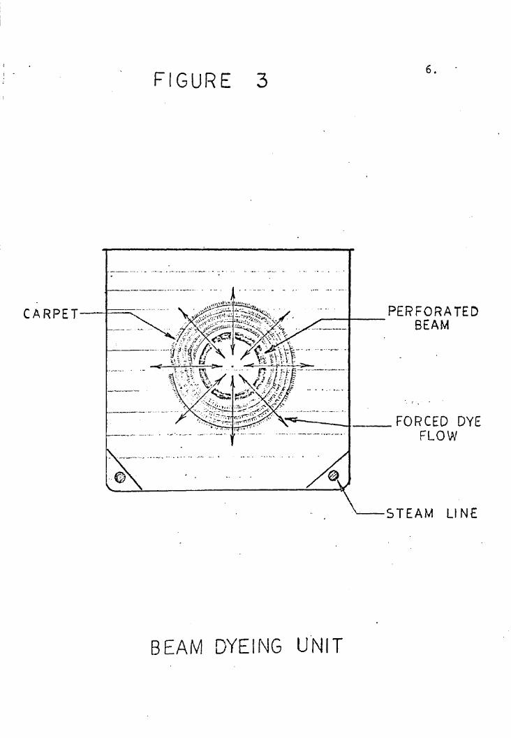
FIGURE 3
----· ... ··-··· - --- ···~·· · - - · ·-· · '" · · - · - · . ... . .
6 .
PERFORATED .---1-- BEAM
,...q. ___ , __ FORCED DYE FLOW
'"'---STEAM LI NE
BEAM DYEING u·NIT

7 .
the slowness of the procedure (which is approximately that of
the beck process) and prolonged exposure to elevated tempera-
tures.
In the roller padder process a set of sque~ze r olle r s is
used to impregnate the carpet with dye liquor by continuous
passage of the carpet throueh the liquid and then between the
rollers. The carpet is then fed into an oven for dye fixa-10
tion As the use of the roller padder is currently under
development, definite advantages and disadvantages are not yet
known.
One major disadvantage of all the above processes is that
the dyed carpet mus t be dried. Present vacuum systems are
capable of re ducin e moisture in the carpeting to only about
1 25% of the original carpet weight, and the removal of the
remaining water mus t be accomplished through evaporation.
Application of the dye liquor to the carpet in low per-
centage amounts (lesa than 100% moisture content) can be
accomplished using the roller padder technique. In orde r to
apply dyes in low percentages, the voids in the carpet must
be reduced in volume at the time of dye application in order
that the liquor is spread over the fiber surfaces rather than
into the voids. The dye liquor .should not be applied to the
carpet until the voids a re rnini~ized. This can be done by
expressing (injecting) the dye liquor into the carpet at the
same tine the voids are minimized by the pressure exerted by
the rollers.. Figures 4 and 5 show conditions ~or expressing

TIME---~
The nip width N, is proportional to the
average radius of curvature R, and the
deformability %, of the rolls and also to their linear loading L.
Noel.!. E
Jhus, at constant loading, fhe nip width can be decreased by reducing both the
diameter and. deformability of the rolls~
a.1-"C "C
TI ~1 E ------
Impact c,,nditions are obtained when the rate of rise of pressure in the nip
a.
is high. Clearly the nip has to be small and the rolls must turn at a · high speed.
FIGURE .:4

-:,~ . . ~,, ... : ".:~~= . ;., . ;:.: .. - " . ":.::.:'.'-.. "" . "'!t. .. . .. .. . .. . . . ' : ,..,: .. . t·~ ~~----.,.. ·------\ ••l;i, •• i.;,,..,,,..,J•,• 1._......._ . ..-1 _ .. ,., .. ' • .... v - .-.t#,".:'i" L: .. _ ·' •c , -~•'• ' • • ·~"" ._ , , ., ,. '• • I, 1' .. ,r, •••H • ..,,_ ,, ,, ... \_ ~ . ' \ :: . . ~ ' .· . ' ,,. . . : . ··.
. . ' ~ , . . . .. . ', . . . .. · ~ .. ~ ~- . ...... . \ . ., . " ' < :~, ''~~.. : . . . . . : .; . ... '\t . ·. '. .
. "" "\ ' . '
· .. \
'\,
" . ).. . .. ·. "·~ . ' !. . .
~ ',\ ~ ; : .. ~. \ • '\ . \
· .. '-'·\_ "\... ·1.\ . . " . .. ~~ ... • '\ .•
. ; ·~ - ~ . ' "' . ~ . '\ . "., ". . . ~
'~ \. . ' .. . ·\ \. . " ' -~ . ~' '"'- , ' 'I · . .:.- ., '\ \ : \ . ""·.~~.~ \\ . :::: ~~ ' · ~· .. ' /~' '., ~ . "· ·. \ \ > \ ~ "-:,
. ~ '\ ·-·· . •. . . ~ ' . ,,: . \ "
. . • \. .~ . ~- " .. '" ., \\'\\ ·t \ ~ D 1lJ '~\,: /:-:~·> "· .. ' ~- : \ ... \ \.: )\ \" ~1 ) \· ... } \. J_j:~ l .. ~ )i· ) ! .. ,! ~\ . )~~ ~. -~ ··I· ' \. . ·\ ,.. . ,. "1 J I . I U-:.. \ . " " ' l " j ' ' 1 · ( I ' "-' ' · , ' · · l \ , . "· • t .. · l · 'r· i ·. j , . \:. / I ' .... · .. - ... . · . '\ "
t 1 ' I 1
' \I ,., ' , , \ \ ' ! I. I / _:...,_:;.-- : ·:~ ;._ . . "· . .. " . '-\ ) .,. --· r~·..,\ . · \ ·• . J ;.r----- . . '. ·~ '\ . . :1 . ._ .. ·... I ':': .. :<, . . . .· :,, " ' : J \ ... ·"
('
. '·. ' .. " ' . . '\ . . . . ,..t ---": .. . ·.,. ' · . . · ~ ~ . \ '\ ' . .. ·; " . . . ~, ...
. ~. .. !J__-----'J .... . 'l_. ! \. .. . ,.. ~, . , ' . ~ . . '
~~~-~ . >'\·, '·,., . . -;·,·. 0. • , •. , _,/ "·\. : '.' \ ' . . -,. . ":. :-: . . .. . "'-· . . \ '.'.;. "" . ' '\, \. ·.,\'.,. . . .. · ,. . '<~ .... , · 30 YD/MIN
.... ' '\ . ·" .. ~ -.; .,. . ..
"'-.\ _,,,. \, \ ,W:.~~:.~ ... ;5YD/M\N WE\.L DEFINED
\ \. ...- --· ~- < IRREGULAR PENETRATlON ~......... 7 !1, YD /M\N PENETRATION PR\NT
NO PENETRATlON ONL '{ /(f CENTER OF PR.INT FACES
FIGURE s co

10.
dye liquor into a voven fab-ric by the roller padder method.
This roller application of the dye necessit a tes running 11
the carpet at speeds in excess of 100 yards per minute (To
provide the reader with a basis for comparison, the general
magnitudes of production speeds for various carpet manufac-
turing machines are: tufter, 33 yards per hour; knitter, 18 12
yards per hour;0
loom, 3 yards per hour · .) The presence of
small protuberances (e.g., a knot in yarn) vould cause pene
tration bridging (undyed areas) to occur as high speeds vhen
long rigid faces, such as the tvo faces forming a nip in the
roller . padder, are used. As can be seen in Figure 6, the
divisions of the rigid rol l into smaller units vould add flexi-
bility in the dyeine of the various carpet styles that should
be processed on the proposed machine.
After reviewing the various dyeing processes, the require-
ments for a nev design vere formulated. These requirements
are:
1. Applicability to any fiber;
2. Lov weight ratio of dye liquor to c a rpet (less
than 50%);
3. Applicability to non-uniforc surfaces;
4. Dyeing speed of 10 runnin ~ yards per minute;
5. Minimum color change~over time {less than 10
minutes);
6. Impact intensity independent or carpet speed;
7. Reduction· of time the fibers are exposed to ele-
vated temperatures.

f 1 BRlDGING \N THESE. REGlONS
.. ·-~~ ·~ ·~ , u " r'Wi' •rrc•nt i* 1.agw•Mj+F ffkM 'RiFP :m:1w11 $ 1 +
F ? A&e e H e ' • @••t~ .4np1 'W If . ¥ '*f5SID WN#i##¥Zi¢¥ '*W'S'4'£21.i"E 2#11Wt«u:;nmn
APPLlCATtON TO Hl-LO CARPET\NG \S A PARTICULAR, ALTHOUGH EXTReME, CASE IN WHICH TH\S TECHN\QUE CAN BE APPLIED.
. FIGURE 6
11. .

12.
These requirements of the proposed dyeing process dictate
the establishment of specifications for the machine. A lov
weight of dye liquor to carpet weight infers impact appli
cation methods. This low moisture content redu~es the heat
requi red for drying the carpet. Furthermore, impact appli
cation of dye liquor in these lov perc entages al l ows the use
of additives which further shorten the d r yi ng time. App lica
bility to non-uniform surfaces means dividing the impacting
face into areas having maximum dimension of 1-1/2 inches
instead of a long rigid face. Impact intensity should be
independent of carpet speed but the impacting frequency must
be related to the carpet speed to achieve complete carpet
cover.
To illustrate the complete carpet coverage. assume an
impactor face one inch wide . This would require 12 faces per
linear foot disposed · in a row transverse to the advancing
carpet. Assuming a striking l ength of 3/16 inch in the direc
tion of the advancing carpet, a figure indicated by previous
experiments, and an advancing rate of 10 yards per minute , a
striking frequency of 32 impacts per second (or 1,920 pe r
minute) would be needed to obtain continuous c over of a strip
the width of one impactor face. The fo r o of impactor system
proposed for the new dye - application equipment must neet cer
ta.in criteria, 'namely-:
1 . Ability to p roduce the required im~actinp, fre ~uency;
2. Su·fficient im:;iact intensity for dye pe'netration;

. 13.
3. Adaptability of impact unit size to a machine frame;
4 . Capital cost of machine construction.
Several possible impacting systems were considered, and
comparisons were made using the above criteria. From this
consideration the system designated as the · " rotary pendulum"
was selected as one of the prime candidates. The rotary pen~
dulum had been attempted on an early prototype mach ine for
print application but vas set aside because of the difficulty
in obtaining continuous i mpacting at the desired position.
However, th e basic simpli6ity of the rotary pendulum indi-
cated that a mathenatical study of such a system to obtain an
understanding of its operation was worthwhile. Thus, control
of this system in a repetitive manner for use in the propQsed
machine migh t be achieved . Fron an understanding of the
rotary pendulum, i mpact at the desired position with correct
radial positioning of the pendulum, might be achi eved if the
proper paraneters could be determined.
Thus, the object of this research was to develop an equa-
tion describing the motion of the rotary pendulun , solve the
eouation a nd annly the solution, if feasible, to the construe-- --tion of a device to achieve dye application to carpet by
impe.ct.

14.
II. THEORY
A pictorial drawing o~ the various coreponents of the
rotary pendulum system, indicating hov they are arranged rela-
tive to one another, is shown in Figure 7, Rotation of the
hub moves the pendulum head along the impacting ~oll-carpet
surface until reaching the point at which the pendulum can
swing tree . The p~ndulum , swinging freely about the pivot on
the hub as it rotates, strikes the carpet and dye reservoir
which are passing over the i mpa cting roll simultaneously .
The impact expresses the dye, carried in the reservoir, into
the carpet .
It vas planned to heve the pendulum strike the carpet
when it was in or near its radial position, then follow the
moving carpet surface until it lost contact with it and finally
swing freely into the radial position again at the time the
hub has completed one revolution froQ the previous impact.
Any tendency to swing past the radial position co~ld cause
jamming of the pendulum into the impacting roll .
This plan demanded that there be a certain relationship· . .
betveen the hub radius (a) and the pendulum length (L).

I I
I /
Pl CT ORI AL DRAWING OF ROTARY PENDULUM
I
--............. ., '·""' "-',, "-,.
/ /' -·-f. . . 7.5d' / ./ ,. _. . -· -- ; . ... -....
'·" \ \ \ \ ~
' \ \ l -t -- L \ . '
I \ _l Pivot /11· ~---------cl Pendulum
roeai---- H C?ad \ ! I . . .. . - r . ·-.. \ \ !' I ..-
\ \ I / . I ·,,'·,. \ / / . ·, ·, / I . \ \ . / ".
'\ ·-.,, /"· / I/ '-- \ ,,....-4.50 '- ·, ., / I ....-1 ----...__ /<, • , / ' F • :V \ '· ' . __,,, . ..... \ " ·~ ..
\ I ; I
I
--¥- I ~-~~~~-----" ~
~ . FIGURE 7
Impacting Ro ll -

16.
Furthermore, believing that the physical quantity required
to express the dye from its reservoir into the carpet vas the
momentum of the pendulum, an exper iment was performed with
impactors used in an earlier prototype machine and the magni - . 14
tude of the momentum needed was determined to be 13 kgm-m/sec
In order to facilitate fabrication in the shop the dimen-
sional limits *ere placed on the sum ' of the hub radius and
pendulum length et 7,50 inches, and the impacting roll diameter
at 9.00 inches: This meant that the sum of the hub radius,
pendulum head diameter, and impacting roll radius could not be
greater than the distance between the centers of the hub and
the roll . Othervise, the pendulum head would not pass between
the hub and the roll . Assuming one pendulum per unit width,
with the above dimensions, a pendulum head mass of approxi -
mately 225 grams would be required to produce the momentum
believed necessary at 1,920 revolut ions per minute for conplete @
penetration of the heavy carpet (45 oz/square yard of Acrilan
by the dye liquor. The size of the pendulum head neeting the
above mass r equirements end dimensions is 1-1/2 inches in
diame ter by 1 inch in length.
In order to determine the effect of the hub radius (a)
and pendulum length. (L) on the motion of the pendulum it v as
necessary to derive and solve the equation o f motion for the
system and then ascert a in if the desi red operAting conditions
could be fulfilled.
These operat io nal condi tions a r e that the impact occur

17.
near or at the radial position, that the angle the pendulum
makes with th e hub radius be decreasing, and that there be no
undetermined velocity c omponent upon r elease from the impact-
ing roll.
Figure 8 is a diagratl of the rotar y pendulum at· some
point in its notion showing the forces acting on the pendulum
head . To simplify the problec initially , the total mass of
the pendulum will be considered located at the center of the
pendulum head and gravity was n eg lected. These assumptions
are justified later .
The horizontal and v e rtical components of the force (F)
exerted on the pendulum head produce correspondinr, acceler-
ations of the mass (m), and the resulting equations of notion
are:
mx = :..F cos o<
my = Fsino<
Relative to an origin at the center of the disc
x = asi n0 + Lsin(e+¢) where e = - wt
also
y = -acose - Lcos(e+~}
Taking the second derivatives of x and y, and putting them
into the equations of motion give
m[ - av2 sin(-wt) - L(w+i)2sin{-vt+¢) + L~cos( -wt+¢)] = - Fcos~
m[ av2cos(-wt) + L ( -w+i) 2cos(-wt+~) + Lisin(-vt+¢)] = Fsin«
Multiplying the first e quation above by sin<'( and the second
by cos<>< , adding and si:tplifyin5 g ives
u n ;,,'1.RY UNIVERSITY 01=' rtlCHMOMC
ViHG1NIA

a ---
FORCES ·oN ROT ARY PENDULUM IN
FL IGHT
I I I I
-+-i e I I I I'
1\ I I \ : \~ I ~, G , '/J o< : ; /.ef\/-4···- --4-"'
1 Fsin<><1--/\ I I \
I . : I I
I I I
\
FIGURE
18.
~Fcos~
-m
8

19 .
.. ¢ ::: -
~hich is the equation for a simple pendulum when g is replaced
by w2 a • The de s criptive name of the i~pact device or rotary ~·
pendulum naturally evolved from the fact that its equation of
motion is related to that of a simple pendulum ~

20.
III. SOLUTION OF EQUATION OF MOTI ON
This section deals with the method used to obtain the
specific solution to the equation of motion of the rotary pen
dulum which vould position the pendulum radially at the moment
it strikes the impacting roll subject to the condition that
the pendulum started its outward swing upon release from the
surface of the impacting roll . The rotary pendulum arrange
ment on which the computer study is based is shown in Figure
9. The angle K is the arc the pendulum pivot traverses from
the moment the pendulum head swings free of the impacting roll
until the pendulum, if it were in a radial position, would
strike the impacting roll when the pivot was in a horizontal
position. The angle ¢ 0 is measured from the extension of the
radius passing through the pendulum pivot around to the line
from the pivot to the center of the head (CM) at the moment of
swing free. A is the angle between the line connecting the
centers of the hub and the impacting roll (00') a~d the line
from the pendulum pivot to the cent e r o! the i mpacting roll
(CO') at the momen t of penduluo release. The equations and
parameters used to ~etermine the initial values at pendulum

____ ....__. __ ,._,,_ _____ ..,._ ..,. __ .. 4.-. ... _ _ __ , _ ...,,_,-~~ - - - ...... ..-... .. _ ·- -
~ ··--··- -----~ -~ .
/_,/ ~
_a \ I
\
/ ...... -~·-··---·-/ ____ ,,...... ····-.
/
/ --------, ... ,
/ II
K. ' '\.,\
I I
I ( .
I ! I
~ L\ I
\ \ c \.--~
\..--- ----- '---00 ~ \
~-~
-.............. --- --FIGLJRE 9
........ ... _
\
'.
ROTARY PENDULUM ARRA ~~GEMENT /\f\JD
PA RAME TE RS ON WHICH THE COMPUTER
STUDY IS BASED
cf
OC=a
CM=L
a+ L = 7. 50"
I\)
I-' .

22.
release in finding solutiobs to the equation of motion are
shown in Figure 10. The purpose of the series of solutions
to the equation is to determine if the specific solution de-
·sired can be obtained in the range of possible parameters.
Other than the physical parameter possibilities, the series
also includes rotational velocity changes in representative
steps up to th; maximum projected velocity of 209 rad/sec (1920
rpm). Thus, from start-up of the rotary nendulum to the final
operational speed of 1920 rpm would involve a transition
through lower speeds; any existing condition whi ch might
cause difficulties should be anticipated.
The computer group of the company was requested to assist
in the study by using the Pace 231R analog computer to plot
the curves of the pendulum motion fo r a series o f cases . The
computations were based on initial values obtained from the
equations and parameters in Figure 10.
Figure 11 is an exa~ple of the graphs obtained in the
series of case studies. In each s tudy the an F, le ¢ between the
pendulum arm (L) and the extension of the hub radius (a) is
shovn, alon g vith the sine and cosine of ¢, and the eneular
velocity, a¢/dt . The aneular velocity of the hub is w radians
per second. The inclusion of scale factors (i.e., 1.4 x io- 3
in Figure 11) is the practice of the computer group in making
permanent recordings . The horiz ontal axis of the graph is the
time axis, where one machine unit is the ti~e interval meas
ured from the inst an t the pendulum swings free of the impacting

23 .
~FIGURE 10
The folloving equations and parameters were used to determine the initial v alues to-be supplied to the computer group for use in programing the analog computer.
Radius of Circle 0 is 7.50" Radius of Circle O' is 4.50" Pendulum h ead diameter is 1. 5011
a+ L = 7.50" Radius of pendulum head center around Circle O'
center is 4.50" + .75" = 5.25"
¢0
is the angle the pendulum relative to the extension of the bub radius at the moment the pendulum is released from the impacting roll sur face.
From Figure 9, it can be determined that
0 . = cos-1 [ 83 . 81 - _a_~ _ _-:_{_1.1._~7~-=~] o · 2a(l2.75 - aJ
and
A = sin-1 [ ~ sin ¢ 0 ]
83.81
K (in degrees)= 360 - (~ 0 - A+ 35°0') o r 325° + A-• 0
35° is determined from the geometry of the me chanism. K (in radians) is equal to the angular velocity {w) times the time (t) to r otate through the anele K.
Hence, the time can be determin ed by
t = K (in radians). lot

1. ! . I. I i i ! . I
24.
roll surface to the time the exten~ion of the hub radius is
in the impacting position (horizontal). To find the value of
any one of the plott ed variables in terms of the original
problem, divide the included scale factor into the correspon-
.... rtnen
ding value on the vertical axis. The sign of ~ has been chosen
positive when L 11
la.gs11
a, and when L "leads" :a, ~ is negative.
Figur e 11 shows the pendulum (1) l agging the radius extension,
(2) passing through the radial position, and (3) leading the
radius extens ion.
Figure 1 2 shows the percentage of the angle K to obtain
r adial positioning of the pendulum as a function of hub radius.
A plot of the rotational speed of the hub egeinst the percent-
age of the angle K for radial positioning for various hub radii
shows the pendulum response to be insensitive to the speed of
rotation (see Figure 13). The case study plots can be divided
into two separate groups which are (1) p lot s to deter mine if
the specific solution desired could be obtained in the range
of possible parameters (a= 2.0 to 4. 5 inches) ; and, if so ,
then (2) plots converging on the specific solution found by
reducing the increments of a in the indicated r ange .
The specific solution desired is where ¢ is zero in 1.0
machine time unit. Case 36 (Figure 14) sho~s ¢ has decreased
a l mos t to z e ro and L is lagg ing slightly . In this case study
the hub . radius ·is 2.25 inches and the pendulum length is 5 . 25
inches . The dimensions used in this case study were used to
fabricate ~he first rotary pendulum.

~~.·~~~ ! .
+ 1.0 ---·- · · ··· · ......... .. ... .. ~ :-- -·-····· ··--- ... -~ • ...:..-..·· --·--·· •• k • • •
M t.8 A c + .6 H I
· ~ +.4 lj '· u +.2 j ..
N . i I · 0 i ··· · · T . ! . ·-··-· ·--
! - z L • I
! .
I .- .4 t
-.6J !
-.8 t I
-1.0 --------.---. I. . . 2. . 3 .4 .5 .6 .7 .8
MACHINE UNIT
---Pivot
-----Hub
\ LO COS~ ,, Cl '-:: 6.0 L= 1.5''
~ .. Time Re-q uired To RotatE' . . Through An g le K
<D Lagg·i ng •a•
cP Lt>~ding ~cs·
. .ia ['s· l'h . il \\"""' 0.3 q ':3 = \f' = 0.6 ra~
\-ii l.OSIN~
J.4x 10·3 ~ ·
,9 1.0
FIGURE II
I\) Vl

PERCEf.ITAGE OF K FOR Rl\DIAL lr~PACT
w w .ea .;.. Ul Ul en en ....... ~ en ~ · : ~ ~ ~ ~ ~ ~ ~ ~ ~ ~
-~:~.;~~1 .. _'t itill :·· I' !:B. t f ... j I rtr ·wt. lfl. t : .. : . ·H"· -:r1nun ~1~~ f~~ . . .i i. ~ . ·m . . .': . . : .. t' : : : . '.I:~ ·~ : .. -~- ;ft :Lt . >r r IL . l tu . .t . ittl .. I· f~ I . . .. t .8rr fttt t . IT{ . t rr . . t ff
I I l l ~ . 1 . l: . . . .. . . • t . f. i-~ 1 I • : L . . . • . . ' . . . . . : : . : . • i :~. ·t L t-:-1 ~ '. :I'· . 'T . Ii.. . . .. ' . . . I • • . . . • . 1 ~ ., . iti . 'I t I . t I:! T: . . . . . . . . ~-~ BJ ... ~ H . i1 t , -t .. . 1 a i . . . . . . . . . . . ~ · 1 [1
1
m t ~i I !· I . . . • If, • t . 1. . '
N 1 ii~. l ill ui . .1 tb1 t .. M r. .. ~ t . Mt- . . . : :tl . t . . ·I !· • • t . . Fi 1 rrmw (.,, 1{1) \ 'lfttl I \. I !•-I. i\ i ·1 ji 1 . Ii V' 11,·ur -1111.. . . :i l.t .H I l: . 1 ' · 1· . . .. , t t r j fTTIT.1~ -~~; 1#.tij;:i I: '.l:i u .JJ :1 i l 1 . t i - - : u, q H .. n rr . ~ . . . . . . tl. 11 :..:.; ;,;:.;-.~. 1w; ,
lfr.1i'1 l \ii :itt\ _ .. r .. :. :h .. 11· d r' lfl=1i .. 'f ·. t T . · · .. - . ~ i 1~-. 1· · . m· ~_ .. ,·· -1· i·lttfir[ r1 ~· i .t ,. i.. 1 . • . l.n l 1 . . l Wu 11u !:i r • !F . ll ~-· .. . i . Ui 1 ~
l jr•· fffi·t .I J ·I i · .• ·1 . •r -~ r 1.L :'t. j . · . . ± 1 ~ · . l J • -rT~· .,.-~· · · . p-.. u i ~l · i!tr_ u.\ ~- 1, .- .. .. • . . : :i ·. ·· J :~1 _ Jr. 3=, ·;· 1 ·~· :·. _. : . • . · ; 1 .. :.k& ..... ::-r~"·d-1 . . · · . , :· . ·li·1 u : · ·pi-.
~ 1 iJi' J n1 TD1 h t J -1 · l • .1 ,._. -r . .. l 1:1~ · u- ti1 :T t ·. · . 1, · . . 11 · .- 1.ft:. •... ;;·: · ~ Ll tl 'fl -. . . . . . . · : m c::: w £ "• I.ill. !. .. . ·· .L \ I " 1l 1 tl• · - , ·· · ,;~~ .. . ti r.t - · · · - -l!l ·~ c, 1.j i p 'H ntp .. ·-.· · 1 · i: · 1 i · . 11 _ ~11 · · ._ -t J IT Ti·.~ . -~l"fiJ._} ··· · _ . t.1·1· . · . . . . . . . til· I .·! . .\! . J. . ' l " . . r I Ji . n t - If j · 1 ~~~ l . . . . . . . . . . - ti _ !tili1 ~f ff · i:f. . . T ~ · 1 :T ·• 11· fl~ ·: 1: :1 1· ·1· :n nf r<:.~,l:;rrW j . Ji · · · . i· . · i· . · · . . ·. . . · ~- ·• ::;: U±ft ~·L n i l 1 1 · 1 1 r 1 \ .. . 1 r r ~1 ,£ . 1 tt !· r
1.u J ~ · , H 1 Ii 1- t - . - . . . 1 · · ·: . . · . . . ..t
;:;, ;11q t ! i ·-n1T · Ti1 ~: m. , .~ 1: _ti. . 1.J .. ··Tl r)?-~:ii:~: · . 1· :+·: · .. . · . , .. .. . 1 . . . . _-:: . - 1·
1· 1l . JJ:-rr· · 1 w· .:J!I · ·I + - f r t t1+ ~"r L., 1. r · · · · · · · · - 1 .. . . . C:: .:'.·, . . , · · .. : · . :+ ... I IT .. ". ... . .. . · · . -~ :: · :_' n .L • , •• '_ , . t'· .· . (I') • . 1: . .. . .1.. . . . • ,. H 1 _ . . _ +• . ~, ~r .. i _ rr . , . - ~ 1llii J; .. 1 I t · 1 .. II . u u : . ! ti 1 -rt 1 ~t-;.:.1 lJ 1. - 1 tt1 . .. . · · . .. t . : · . :· 1 .. . .: : 1 ( . J rliH I» ui •. ~. i 1 ~· ¥il·l'l l:! !-l l 11· ~fT 11 :: t .± ' l : J1 111: _~"'il'' · ~!1 :Jl l H '· , li' · !J_ : . ' •. • ~ ..•. . i . . I . . ' ·' . , r•' .LI rrftt11.
l.:.p · _i: i , u. J. • .J. i:i-· li. tf · · 1~.d U: ll-+ U: u l± · .1tll ii .. f . . . . . ~ ' f£! -Hl ll-ttl i.1 · ·ry ··
1 t rr H ; · · · ·
1 iJ~:. · ·• · t+ .it ·I- j ~ · rr. I .f! · · · · · '
t . • . J t f r , I ' I:- ,.J -t· r:~· i .. • - ·- . UJ1UL1J .• I I I . Ii · . 1 . IT.Pf ~ l lt !Il·t 111~ .:. . lll T 'l Jt 1 ~ : .... . - .- . t f· ~ HF :;i 1 .. ; · m1 ~- ,,. 'i Jt .. 1
1 .. 11 11 1 11~?.;1 • · 1J · 1 i\ i1 ul1 ~- · • t · ~I H 1· r. ·· · · • · · ·! ·
~ ;l i[l1 r ~ ~· .J11 1:.1!1 1t 1~~::.':i~ r · l 1 I 1 Lt f! ·ii~ •l t HJ 1-1 .. tf! ti t . · i: -• . · . · .J · JJ . · · · . : 11»+ Q lt HP t 1 11·1!111; 11· x,..· · 11rrnr 1T · ii !t · r.tl n rr· iD -1 J J I · 1 •1
1
en f'" U. 1u! l . 1·,· t ll Ul .. i.:)~·: '." ! !ll ttHI l L · lllllJ !:h~~ ti. 1.f-! t . 11. - · I · ~ . . t . ·1 ). ri i , . t ::
0 ' l• ' 1·1· .1" ' ~! 111. I·"'" ' "" I! ··fT1:T1 lli1l '[ ii I 'I' Lr ,. 'I l 'IT I r· I~ I I [ I ~ il j i ~ l' j tr. I!+ ' . !ttl ~~ ! 1jii i, 1~1 '. .• ?'~'.: jE ;i l 1' U i H· !;.1.l • i l·t l r ti !1 il il hl l ·i H · cc.! · · · ' lj . . , . L .
1 .,.. • ... .._ p- ~I , ...._ IL;~] l • ,_,_ :Tl t :r Cl.I ,_, f 1 H+t .
. .. . I j .. I I I • . .. I I r :-ri- r~ ' • • .• j4 • ,. ·! FF! .. ·H• . . t [T 't . .. tf l :r . . I ' n:• . ! ! I rr. . . '.J111 ~' i!\Ui ·~~'.;i;' 1 fft .I); if I ! i ~ il .' c~ 11 ! !1 !1!ff1 !1[; tj 1; ~ · JJf '!. '' ; 1!
1 . ! 1\u1 l~ i1 Ji , · j !l 1; ~I "Tl ! tflliu!l~':'~m"~L.i1 ijffi :t.@1 _r1 ~ JJ-1 liff 1 TI .1~: :\ ·1 nir ~ ·j nn 1 ~ rr '~ .. 'l [1-m -J111 -1 ~ 1 , 1 1 lti t i~ Hi h · 1r n~. j , = · (j) ~· H.!:l:r· ·
I H ,tt ... ! I .~, ; ltr~t II' l i 1 w i· '·:tl Iii I 'ff Tff• • H tf titt ttft 7t ~ titt1 itrrtl .. ' • IT-1 t Tt iT jJ itf I i 1 t ' ti l T . ~~ l ... I I 1-;I . c I@ .; 1-.1:IJ/, /' •l : :!, 1'! !: : .;. '· IJ i ~ 1.1l1' Hi ·· 11! l::.illlii;_l~ t't 1' ', .. 't ,t! ; L l fi l~ i . 1- ,~ - 1- I ' Ii \ l + T ·.I j .., :::0 _. 1,;. ' • ..b. t•' tt; ••, ... • . t1 1 1 l. ff ' ~1~ ;·-t . ·d_•• :ii l •·+-' tl• f fl· f • t. 41 1 J T ! ' ' !±! .l_f. I !f i - i1 ff~ ~ I f.:_ .; ~~·, .. -. q:r · · [·if.it ~I- Tii·· ff lt' 114tt1 1 r· 11·ff· t:f' J l 1• :1· ··•· f11 ~ 't't. t ·I.,. --R:-! "' •t1 m H rn =1 m~ - !}1~t.f~~'.l ·!" _L~ :~d~ _ n ;1 _ n:: r~-_; ~ -l:t lr:~:llih 1tfillif,:1_l~~!t}fli i _ J . ~ + tir~: WJ -: ~ · 1~ flti 1 ·: .f 1 fl ~ . -~ 8illlliw1 t nnm. ~~ .Jtttr cr .'fo [-dfil mt~rr~[t: J1[Pn lrt 1tH ~l 1-l J. . I~ [ fh m ·. l } tt :rn I' . I I -W~ r TI - 8. : . . . . . ".' "' N 1· i: l.lj . ~~ · Ur ! · .i \i:J.fi . 1-~ t t Ff ~- : :i:! , t· -; 1~ · i+ .i.1 EH ± 1. -i+ . · :l tJ 1 t t· {l _ •. · ± l .
1: f : . · .1:1: . J • . ~: ~rt ~ 1 . T + T n : I·· ; . 1 . . I . . . Ii . . l . . ' ·- . I 1 1 .. I ~ ( . . 1 " ·' '" - iLJJ ~ ,_ ~ -- ~----• • •-• ___ lt~u- I
~
·!'"

RESPONC E of the ROTARY PE No·u LUM to 27.
SPEED of ROTATION
T.. . ... ·r .. I
3.0'' I : . ! . i . . i ! ·: . f
- ___ ...... .... "·!· -·····--.-· .. -· .. : ... . ·- -... - ..... -::······ ·--·--.. -.. ---·-i ---------~-.. - -- -·-·--· ... -............ 1 .. - -.. --
i I ! ; I I t
~20
20
I 4;0''
'
II
4.5.
· 1 l: I !
; i Ii ~ 8 i ~ i . . ' ~---; -------·--;--· ---·-----~- ---_ .. ____ .. ·---,------·---!-··--- .. ··--· ........ _ ..... . ~ ........ .
0 w w Q.. l/)
_Jl2 <(
z a
~10 d CV.
8
1 1 I ! : I ' ! l . f
.! j i ! ...... r I, ···-----··--·---~ ... -·-------·---~. -·-.. ---·-· .. - ---1 ----· ·- --.. ---··: ·-- .. ·-·--· -- ··- . , .. ·--···--"-· . I • I : . ! ; I .
! • ' I ! I
• ! l 1 • ! i I
. f \ t ~ i - --- .. --.~ - ----------·- ;,...._ -·----.-.+-·--.--· ---·· ·---·----·-~ ·- - ~···-·- · · · - ·· -.. ........ -~-- _..._ __ _
: I \ . r :1: . . ~
. j
I I
--ii------. - --··-- - · --.. --.!--- -----·---.. -·;-----· -----· -· --·t-···-· ..... ... --·--1··--.. -------i---... i i l { : I ! 1 1
' !I ' I 1 ~ . I i l j I I
·-------- .. ·-i .. ___ ,__, ___ --· -1-·-· . --·---··-·--·1 -------·~· - ---l----·------·· j··- .. --------·-:--~--.. ------' , 1· : I . . t l ! I : t I : I . . • I t I •' I I I . . I ·; . I I I ; ; I i I • I I I . ' ' ' I ! · i I . . I I ~ I i I . : . . I j , I i I I I 1 1 I i I + __ ·- -f-·--·--··-·-·· .. ···'··-·--l--... --1r -·----·-·1-:--·-.----·· .. -·1·····-·-···:·· .. -·1-· - l i : l 1 I I ! I l I ~ I ; I i I : I I ' . . : ; I . I : 1, · I
[ 1 ) i ! i I . . I '1 I l
. I i 1 I : . . I
50,3_2~·~~-4~~---~~4Jl8_1!.-..~~5,~6-- ~-1-~6-~4~~--72· 80 PERCENTAGE OF K
. FIGUR.E: 13
a


29,
IV. MACHINE DESIGN ARD TESTING
The first rotary pendulum fabricated vas a dimens i onal
model in plexiglas using the values of a and L determined in
Run 36. The hub was rotated at speeds up to 100 rpm to deter
mine how nearly the pendulum was responding to the theoretical
prediction. By means of a strobe li ght and a polaroid camera,
photographs were made which showed the motion of the pendulum .
These photographs indicated that in over two-thirds of the
trials the pendulum was lagging the pivot radius by 20 ° or less
at the moment the pivot radius was horizontal. Some interfer
ing facto r was causitig the pendulum to lead the r ad ius extension
sometimes and then lag by over 20° in other instances.
This variation in angles was believed to be due to the
low power of the motor as surging of the hub was viewed follow
ing the i mpact of the pendulum on the impacti ng roll. · novever,
wi th a favorable percentage of the photographs shoving accept
ab le operation, it was decided to fabricate the pe~dulum in
steel using the relationships of Run 36~
Using this se cond pendulum, attempts were made to obtain
noderate ro~ational sp eeds compared to the desired 1920 rpm.

30.
These attempts were failures. Pendulum arms broke and pivot
bearing shoved danage. In an attempt to · reduce these effects
the cross-section of the arm was continually increased, but
this did not solve the problem of arm breakage or damage to the
bearing. Furthermore, the increase in the size of the arm
affected the .motion of the pendulum. The larger arm in effect
was moving the center of mass toward the pivot, vhich, in turn
was changing the r~tio of a to L causing the pendulum to lag ~S$£,e
the pivot radius to a ~eaier degree.
The damage to the p ivot bearing indicated that the im-
pact was not taking place at the center of percussion. Once
the pendulum design was modified . so that the point of impact
and the center of percussion coincided, the rotational speed
could be increased without damage. The .center of mass of the
pendulum was maintained at ~.70 inches froM the pivot, but the
.overall pendulun length was increased sienificantly to 6.10
inches. This increased length delayed the time of release
fron the impacting roll and, hence, the result was that the
pendulum lagged the pivot radius at impact.
An additional problem evolved as the rotational speed
increased. This w~s the rebounding of the pendulum off of the
impacting roll at these higher speeds. Not only did the pen-
dulum rebound off the im9acting roll but also off the h~b
surface. The continual· rebounding between the impacting roll
and the hub surface meant the pendulun was not being released
from the im!?acting roll surface with zero relatiYe velocity.

31 .
Release of the pendulum wfth some initial re l ative velocity ,
-whether in the direction of decreasing ~ or not, meant that
the pendulum ' s motion was no longer repetitive. Some ~eans
had to be devised to control the point end velocity at which
the pendulum was re l eased . A mechanism called an escapement
was installed o n this second rotary pendulum (see Figur e 17 ).
The escapement ar r ested t he suc cessiv e r ebounds between t he
hub and impacting rol l , a n d provided, a definite point of r e -
lease fo r the pendulum.
~ow, it was found that at rotational speeds in the gen-
eral range of 700 rpm, the carpet backing wns being da~aged and
the tufts vere bein~ pulled out and lover operation speeds were
indicated. However, a pendulum with the same nass as required
by the 1920 rpm condition would not produce dye impregnation
of the car pet at lower speeds if momentum was the physical
quantity required. Previous experimentation with dye expres -
sion had been carried out at low velocities using large masses .
This experience showed that carpet damage did not occur when
dye expression was achieved at these lov velocities. This led
to the consideration of energy as the pertinent physical quan-
tity involved in dye expression and penetration . The magnitude
of impactor energy but not the momentum at 300 rpm for the 225
gram pendulum vas near that of the machines from vhich experi -
ence had been dravn. Hence it appeared that the physica~
quantity desired was not momentum as originally believed, and
th~s ... l .o_we!' angula,r ~pe_e~s .. ":P_P~_ared feasible~ th the above !U'lal•. ysie it ta ~seumed that the stopping ot the hammei- in each c.ase · · waa· undatt eimilar conditions.

32.
The energy magnitude at approximately 300 r~m suggested
the idea of replacing the single pendulum with six pendulums
per unit width equally spaced around the hub •. This last ·
problem was solved by replacing the single pendulum per trans
verse position, which called for 1920 rpm, by six pendulums
which required the easily obtainable rotational speed of 320
rpm.
To ascertain if the above idea was feasible, a dyeing run
was made using the existing one pendulum machine, and a carpet
speed of 1/6 of the proposed 1 0 yards per minute. This run
vas successful and a continuous strip of dye impregnated car
pet the width of the pendulum head was obtained .
When considering the usage of the six pendulu ms per posi
tion in - a machine which ultimately would be 180 in~hes wide,
the problem of positioning the pendulums so that they would
not interfere with one another arose. A satisfactory tessel
lation for positioning the pendulums was found using impactor
faces 1 -1/8 inches wide and is shown i n Figure 15. This
tessellation h a d the advantageous built-in feature that pro
vided for overlapping of the impact areas. This overlapping
meant tha t a carpet would be dyed uniformly. The pendulum
arrangement and pendulum head width was such that the total
area of the carpet would be .uniformly i mpac ted with the ex
ception . of three-fourths of an inch on each outside edge.
However, this portion of the carpet is trimmed during further
finishing steps and presents no problem .

180°
TWO IMPACTons 180° APART LIE ON EACH 3/8" LONGITUDINAL POSITION
r;•c;c:;c~;· .~ -;~~~~t~ ··~~~:~~~~~·~•m••~•
• _ :. ·~'::f:".::-~;:::~?..::. ::::::~·z~::-~7. .. ~ ~:~: --· ; ·:-.~·1-- r;;i~9- -- - - - - -t .::~ . .J-.: ~·~~· - · ·~ :..~-~-- -i; ~ ::-. : ,- - - ·- - -r l
j I • - . • • ~ j ;..,.__. . - - ·· ·
L1MPACTOR HEAD IMPACTOR PIVOT ;.... .. , ...... -· ... ...:
180° EXPANS\ON OF lMPACTOR DRUM SHOW\NG IMPACTOR TESSELLATlON
THE ORUM 15 OtVIDEO LONGITUDINALLY INTO 3/a" DIVISIONS AND TV'JO IMPACTORS 160° APART ARE CENTEnED ON EACH 3/811 DIVISION. THE IMPACTOR HEADS ARE Sx3/s''( IYa11
) \VIOE so THAT IN ONE REVOLUTlO.N OFTHE ORUM EACH 2/8" LONG\TUOINAL POS\T\ON OS: THE MATERIAl UNDERGOING IMPACT RECEIVES SlX IMPACTOR BLOWS.
SCALE: ~ULL SIZ.E
FIGURE 15 --.

34.
Intermeshing of the impactors vithout collision among
themselves is dependent upon control of ~he pendulum motioh,
both before and after i~pact. Control of a pendulum means
that the pendulum ·must be arrested and released unfailingly
from a predetermined pos ition. A mechanism called an escape
ment was e mployed to assist in arresting the rebounding pen-· .
dulums and to provide a definite release point. The escapement
is a flexible surface which moves in a circle around the hub
axis. A feature of this escapement device is thet the pendulum
release point can be varied, thus causing the pendulum to strike
fr om the radial position or any other desired position in its
flight. This feature of the escapement is used to vary the
striking velocity making it possible to regulate the impact
energy to . the penetration requirement of the particular carpet
being dye impregnated .
With the employment · of the escap ement the requireme nt that
the pendulum be radial in one machine unit of time from the
ori g inal release position was removed. A ratio · of pendulum
len gth to hub radius vhich p roduces a more rapid closure rate
of ¢ was now needed since an effective escapement would reduce
the angle traversed by the pendulum during free fli eht . Since
the equation of motion involves only a ratio of the hub radius
and pendulum leneth, any values of a and L can be used as long
as the ratio is within the limits of the original solutions.
Information on the mo tion of the pendulum can be deter mined
for any values of a and L f rom those ~lready calculated by the

computer. Figure 16 is an example of how to obtain this in
formation for any ratio within the above limits. The layout
of the rotary pendulum assembly is shown in Fi gure 17. Fig
ure 18 illustrates the arrangement of six pendulums which would
be found in a cross - section of tbe machine 1-1/8 inches wide.
Figure 19 shows the flight of a rotary pendulum from
various escapement openings. From photographs similar to
these, the velocity ·of ' the pendulum relative to the pivot
radius at . impact could be determined by knowing the flash
frequency of the strobe and measuring the distance between the
pendulum head centers. Such .measurements of the velocity in
the above manner show agreement with the velocities that are
predicted by the plots.

36.
FIGURE 16
Th i s figure is an example of how to extract p endulum motion information from the analog plots. A &iroi lar exercise vas ·carried out in· order to obtain the escapement ppening required. fo r radial positioning of the pendulum. Using this opening, the release point relative to the impact ing roll could . be determined . An adjustible escapement a l ong with a stat i onary section, could be designed so any position o f the pendulum up to radial could be used for impacting the carpet.
For example, using the present parameters of the mach ine
L = 4.45" a = 6.31"
a + L = 1 0 .76 "
the escapement opening for radial positioning can be calculated. To convert the present parameters to those of a n analog plot , sett i ng u p a ratio using a/(a+L ).
Pr esen t parameters : 6 .31" 10. 76''
Plot: a 7.50"
Equate th e tvo ratios and solve for the hub r adius , a
or a = 4.40" .
Ho anal os plot exists for ~ = 4.40''. Using the i nformation in Figure 10, the angle K is 27 5°. However, the percentage o~ the hub rota tion, K, for r ad i a l posi tioning can be obtained for Figure · l3. The percentage of K for radial positioning vhen a is 4.40'' (and L = 3 .10 " ) i s 34 . 7 . The desired percentage of K = 275° x .347 = 95°.
The escapement must be opened 49° more than the desired perc entage of K to release the pendulum when the p ivot is at K, in order to allow for the pendul um arm . The escapement opening therefore is 95° + 49° or 1 44° in order to r adially position the pendulum at i mpact.

LAYOUT OF· THE ·IMPA.CTOR ·ASSEMBLY lf\l THE MACHINE
;-ESCAPEMENT . f ~,--------1 2.0 i" ~
,, l • 6.31 ~
- - - - - - ----- -- - '[_'='_J ____ -- --- -- -5~-:- PENDULUM
HU 8----------
STA Tl ONA RY PORTION OF __ ESCAPEMENT
IMPACTING ROLL:--
· FIGURE 17
w -4 .

I i 1-I ·
t ' \ . \ \
( -. . .\ \...::. }
~-- _.,,,/ ------
' .,
-
-

2

40.
V. CONCLUSIONS
A prototype machine as proposed in the introduction to ·
dye carpet was fabricated using the rotary pendulum as the. im
pacting device. The machine would impregnate a carpet strip
4-1/8 inches wide. The six pendulums per position (l-1/8 in
ches in width) concept of the hub roll was used, with the
maximum speed of rotation b~ing 300 rpm. The tessellation
shown in Figure 15 was used to locate the pendulum pivots on
the hub. The hub had a radius of 6.31 inches, and the indi
vidual rotary pendulums (22 in all) had a center of gravity
4.45 inches from the ~ivot, and a center of percussion 5,70
inches from the pivot. The center of percussion co i ncided
with the striking point.
Carpet was fed through the machine simultaneously with
the dye reservoir at 10 yards per minute. The ~scapement was
opened and slowly increased until the rotary pendulums were
impacting in a radial position. The carpet was impregnated
with dye from the reservoir using the rotary pendulum impact i ng
devices.
Conclu~ions which can be drawn from the developments

41.
leadins up to and through the above test are:
1. The rotary pendulum can be controlled and us ed as
a machine component;
2. Carpet can be dye impregnated using the r otary
pendulum machine;
3. The theoretically determined values o f velocity~
position and escapement opening, u s ing the equation
of motion for the rotary pendulum and other infor
mation obtainable from the analog plots vary no more
than 7 percent f rom the measured values.

42.
• GLOSSARY OF TEXTILE TERMS16
BEAM DYEING - The greige carpet wound on a special perforated beam is placed in a dye machine. The dye soluti on is pumped through the carpet from the center of the beam outward and then from the outside carpet surface to the center of the beam.
CUT-PILE CARPETS - These have a surface of brushlike tufts which stand up from the backing , as in corduroy and velveteen fabrics.
DRYER - Various applications of heat to evaporate moisture.
DYE, DY ESTUFF - The name given to solutions or naterials that color textiles.
DYEING - P r ocess of add~ng a comparatively permanent color to any fiber or fabric. Dyes may be either natural or synthet ic, and differ in effectiveness and metho ds of a~~lication .
FIBER - A basic complete unit in the fabrication of a textile yarn or f abric.
FRIEZE - Heavy, rough, fuzzy, wiry faced material .
GREIGE GOODS (GRAY, GREY, ~RIEGE) ·- Fabrics, irrespective of color, that have not received any wet processing.
LEVEL DYEING - The dyeing of fabric to p roduce uniformity of color with no streaks or shaded areas.
MOISTURE CONTENT - The moisture present in a textile material expressed as a percentage of the material weieht.
PACKAGE DYEING - A method of dyeing yarn . The yarn is vound uniformly on nerforated spools or tubes . These p a cka8eS are then placed i~ a special dyeing machine in wh i ch the liquor · is circulated through the yarn alternately from the .outside of the packase to the center and then from the center to th e outside.

PADDER - A set of squee ze rollers used to impregnate any fabric vith a liquid by continuous passage of th e ~abric ~hrough the liquid and then between the rollers.
PIECE · - A length of fabric.
PIECE DYEING - The fabric is dyed a solid color by complete immersion.
PILE ~ The cut thread~ of uncut loops which make the surface of a pile fabric~
RUNNING YARD - One yard of ·cloth regardless of width in vbicb it is constructed.
SHADED GOODS - A finishing defect in which the fabric shovs uneven coloring.
SKEIN DYEING - Dyeing yarn that has been reeled into hanks .
STOCK DYEING - Dyeing loose fibers in bulk form, before any yarn manufactur ing operations have begun.
TWIST - The number of turns per unit len s th of yarn, such as turns per inch~
WET FINISHING - Generally applied to ell finishing operati ons in ~hich the .fabric or yarn encounters liquids as any part of the operation.

44 .
REFERENCES
1 . Barvick- Chemst r and Car net Se mi nar, p . 32 .
2. Ibid ., p . 1 1 .
3. Ibid., p . 11.
4. Carnet Manufacture, p. 1 09.
5 . Barwick- Chemstrand Carnet Seminar, p . 1 1.
6 . Personal conveyance ·rrom E . V. Burnthall, Monsanto Company .
7. Personal conveyance from Egan Hacklander, Monsanto Company.
8 . Encyclopedia of Textiles, p . 505 .
9, Barv ick- Chemstrand Carnet Seminal:, p. 15 .
10 . Encyclopedia of Texti~cs , p . 505 .
11. Paterson, J.G.T . , and Smith , A. P . , A Compendium Report on _!;he Design a~e~_lopment of l!!roa_ct Dyeing Machinery, p. 11 . .
12. Personal conveyance from J. E . Hendricks, Monsanto Company .
13. Paterson, J . G.T., and Smith , A . P . , A Comnendium . . . Dyeing ?·1 a c h i n e r .l , p • 4 O •
1 4 . Smith, A. P . , La.borator_.y_ .. lfotebook C- 47 , p . 44 . ----- -· .
1 5 . Paterson, J.G . T., and Smith, A. P . , A Compendium .__!_J)~...!EJl Machincri, p . 10 , ·
16. Encyclo_pedia of Te~til~, pp . 505-522 .

BIBLIOGRAPHY
1. Barwick-Chemstrand Carnet Seminar. Decatur, Alabama, Monsanto Company, 196b.
2~ Carpet Manufacture. Decat~r, Alabama, Monsanto Company, 19-63.
3. Encyclopedi~_of _Textiles • . Englevood Cliffs, N. J., Prentice-Ball, Incorporated, 1960.
4. Smith, A. Paul. Laboratorv Notebook C-47. Decatur, Alabana, Monsanto Company, 1965.
5. Paterson, James G. T., and Smith, A. P. A Comnendium Report on · the DesiP,n and Develonment of Imn act Dyeing Machiner~. Decatur, Alabama, Monsanto Company, 1967.

46.
VITA
Ashley Paul Smith was .born July 24, 1937· in Charleston~ West Virginia, to Coleman Ashley Smith and Helen Caldwell Smith. While in elementary school he became a Christian and joined a Baptist church. Paul graduated from Thomas Jefferson High School, Richmond, Virginia in 1955.
Paul entered the University of Richmond, Virginia in September, 1955. lie ran cross country and track for the university. In June, 1960 he · graduate d from the University of Richmond with a bachelor of science degree in Physics . While doing graduate work in Physics at the university he was elected to member ship in Sigma Pi Sigma.
Durine the tvo years of graduate study from 1960 through 1962, he vas a laboratory instructor in Physics · at the Medical C~llege of Virginia. In 1961 the instruction of a Physics course at Saint Patrick's High School vas added to his experience. In 1961 he married Sharon Anne Slate of Petersburg, Virginia. They have three sons~ Steven Paul, Scott Ashley, and David Irby; their ages respectively are 6, 3 and 1.
In 1962 Paul accepted an instructor's position in Physics in the Physical Science Department of Northwestern Stete College of Louisiana, at Natchitoches, Louisiana. The following year he joined Chemstrand Company (now the Textile Division of Monsanto Company) in Decatur, Alabama, as a textile eng ineer in th~ Creative Products Group. In 1968, Paul chan g ed to his present employer and location, Northrop Carolina, Inc., Asheville, North Carolina , as a machinery design eng ineer in the Textile Machinery Design Group.
Re is a member of the Land of the Sky Chapter of American Society .of Textile and Manufacturing Eng~neers.

ACKNOWLEDGEMENTS
In addition to those .already ment ioned as r efer e n ces ,
others have contributed signifi c a ntly to the theoreticai de
vel opment and fabrication of the r otary pendulun dyeing mach ine.
Appreciation is extendea to Monsant o Company for the use of this
material and under whose auspices the research vas carried out.
In particular, R . E . Opfer kuch , James G. T . Pate r son, W. T .
Pigot, a nd Bill Washington were major suppor ter s of t his
project.
Dr. Addison D. Campbell, as advisor, and Mmes . T. S .
Boughman and Way ne Burleson, who prepared the manuscript , are
acknowledsed for their valuable assistance in th is thesis
presentation.
A special word o f appreciation is due my wi fe , Shar on,
and my parents for the i r encouragement in this endeavor.